

Page 1
Operating Manual
Water analysis – hand-held
meter
G 7500 series
Keep for later use.
www.ghm-group.de
Companies / Brands of the GHM
Englisch
Page 2

H87.0.0X.6C-01 Operating manual G 7500 Series page 2 of 34
Index
1 GENERAL NOTE ............................................................................................................... 3
2 SAFETY ................................................................................................................................ 3
2.1 INTENDED USE .................................................................................................................. 3
2.2 SAFETY GUIDELINES .......................................................................................................... 3
2.3 QUALIFIED PERSONNEL ...................................................................................................... 3
2.4 SAFETY SIGNS AND SYMBOLS ............................................................................................ 4
2.5 FORESEEABLE MISUSE ....................................................................................................... 5
2.6 SAFETY INSTRUCTIONS ...................................................................................................... 5
3 PRODUCT SPECIFICATION ........................................................................................... 7
3.1 SCOPE OF DELIVERY .......................................................................................................... 7
3.2 OPERATING AND MAINTENANCE ....................................................................................... 7
3.3 CONNECTIONS ................................................................................................................... 7
3.4 SUPPORT AND RETAINING CLIP ........................................................................................... 8
4 OPERATION ....................................................................................................................... 9
4.1 KEYPAD ............................................................................................................................ 9
4.2 STATUS LINE ................................................................................................................... 10
4.3 DISPLAY ELEMENTS ......................................................................................................... 10
5 START OPERATION ....................................................................................................... 11
6 BASICS OF THE MEASUREMENT .............................................................................. 11
6.1 PH MEASUREMENT .......................................................................................................... 11
6.2 BASICS ABOUT CONDUCTIVITY ........................................................................................ 15
6.3 CONDUCTIVITY MEASUREMENT ....................................................................................... 15
6.4 ELECTRODES / MEASURING CELLS ................................................................................... 15
6.5 TEMPERATURE COMPENSATION ....................................................................................... 16
6.6 DESIGN OF THE SENSOR GWO 5610 ................................................................................ 17
6.7 COMMISSIONING / FILLING OF THE SENSOR GWO 5610 ................................................... 19
6.8 SENSOR GWO 5610 MAINTENANCE ................................................................................ 20
6.9 BASICS ABOUT OXYGEN MEASURING ............................................................................... 21
6.10 AMBIENT PRESSURE AND MEASURING DEPTH OF THE ELECTRODE ................................ 21
6.11 CORRECTION OF SALINITY ............................................................................................ 21
7 CONFIGURATION........................................................................................................... 22
7.1 DEVICE MENU .................................................................................................................. 22
7.2 PH CHANNEL MENU ......................................................................................................... 25
7.3 TEMPERATURE CHANNEL MENU ....................................................................................... 27
7.4 OXYGEN CHANNEL MENU ................................................................................................. 27
7.5 CONDUCTIVITY CHANNEL MENU ...................................................................................... 28
8 ERROR CODES (IN DATASET) .................................................................................... 29
9 CALIBRATION ................................................................................................................. 30
9.1 GENERAL INFORMATION .................................................................................................. 30
9.2 PH CALIBRATION ............................................................................................................. 30
9.3 O
2
CALIBRATION ............................................................................................................. 30
10 CALIBRATION AND ADJUSTMENT SERVICE ..................................................... 31
11 REPLACING RECHARGEABLE BATTERIES ....................................................... 31
12 RESHIPMENT AND DISPOSAL ................................................................................. 32
Page 3

H87.0.0X.6C-01 Operating manual G 7500 Series page 3 of 34
12.1 RESHIPMENT ................................................................................................................ 32
12.2 DISPOSAL ..................................................................................................................... 32
13 SPECIFICATION .......................................................................................................... 33
13.1 MEASUREMENTS AND ACCURACY ................................................................................. 33
13.2 GENERAL SPECIFICATION .............................................................................................. 34
14 TERMS OF LICENSE ................................................................................................... 34
14.1 FREERTOS .................................................................................................................. 34
14.2 FATFS .......................................................................................................................... 34
1 General Note
Read this document carefully and get used to the operation of the device before you
use it. Keep this document within easy reach near the device for consulting in case
of doubt.
2 Safety
2.1 Intended Use
The device is exclusively designed for measuring of pH and conductivity or pH and
dissolved oxygen in water (saltwater and freshwater).
Personnel which starts up, operates and maintains the device has to have sufficient
knowledge of the measuring procedure and the meaning of the resulting measured
values, this manual delivers a valuable help for this. The instructions of the manual
have to be understood, regarded and followed.
To be sure that there´s no risk arising due to misinterpretation of measured values,
the operator must have further knowledge in case of doubt - the user is liable for any
harm/damage resulting from misinterpretation due to insufficient knowledge.
The manufacturer will assume no liability or warranty in case of usage for other
purpose than the intended one, ignoring this manual, operating by unqualified staff
as well as unauthorized modifications to the device.
2.2 Safety guidelines
This device has been designed and tested in accordance with the safety regulations
for electronic devices.
However, its trouble-free operation and reliability cannot be guaranteed unless the
standard safety measures and special safety advises given in this manual will be
adhered to when using the device.
2.3 qualified personnel
The device may only be installed by qualified personnel who have read and
understood this manual and who are able to use the devices professionally. Qualified
personnel are persons who are familiar with the installation, assembly,
commissioning and operation of these devices and who have the necessary
qualifications to carry out their duties.
Page 4
H87.0.0X.6C-01 Operating manual G 7500 Series page 4 of 34
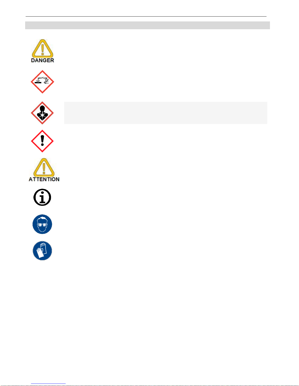
2.4 Safety signs and symbols
The following signs in this document highlight warnings:
Caution! This symbol warns of imminent danger, death, serious
injuries and significant damage to property at non-observance.
This symbol indicates danger for living tissue as well as a variety of
materials, which can be damaged or destroyed when coming into
contact with this chemical. Caustic effect, protective equipment
required!
This Symbol indicates dangers to all living beings that may result in
death or acute or chronic health hazards when inhaled, swallowed, or
absorbed through the skin of this chemical.
This Symbol indicates irritant substances that can cause inflammation
on short-term, prolonged or repeated contact with the skin or mucous
membranes.
Attention! This symbol warns of possible dangers or dangerous
situations that can provoke damage to the device or environment at
non-observance.
Note! This Symbol indicates operations which, if ignored, may have an
indirect effect on operation, possibly leading to incorrect measurement
results or triggering an unforeseen reaction.
This symbol instructs the use of eye protection which protects the eyes
from harmful influences when working with powerful light, UV radiation,
laser, chemicals, dust, splinters or weather influences.
This symbol instructs the use of protective gloves which offer
protection from mechanical, thermal, chemical, biological or electrical
hazards.
Page 5
H87.0.0X.6C-01 Operating manual G 7500 Series page 5 of 34
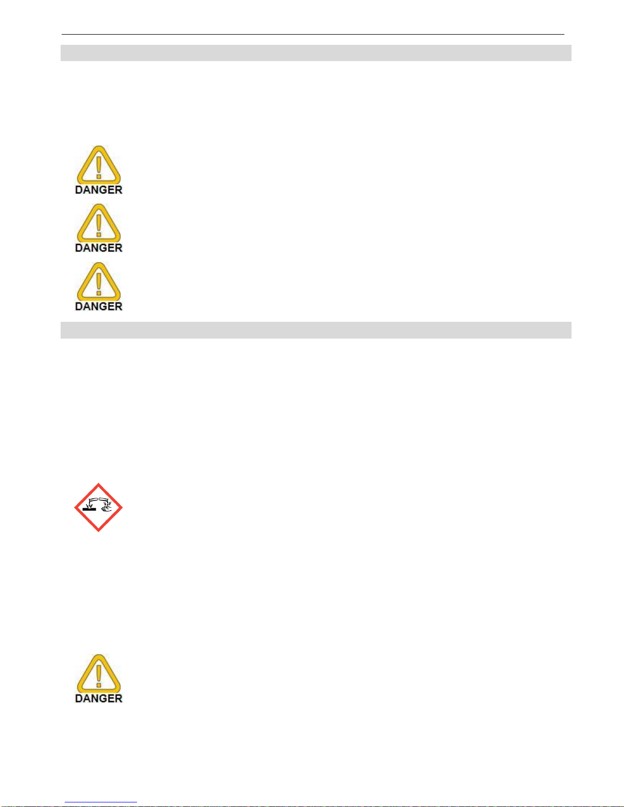
2.5 Foreseeable misuse
The fault-free function and operational safety of the product can only be guaranteed if
generally applicable safety precautions and the device-specific safety instructions for
this document are observed.
If these notices are disregarded, personal injury or death, as well as property damage
can occur.
This device must not at all be used in potentially explosive
environment! The usage of this device at potentially explosive areas
increases danger of deflagration, explosion or fire due to sparking.
This device is not suitable for medical applications.
The device is not suitable for direct contact with food products.
Take samples and dispose them correctly after the measurement.
2.6 Safety instructions
This device has been designed and tested in accordance with the safety regulations
for electronic devices.
However, its trouble-free operation and reliability cannot be guaranteed unless the
standard safety measures and special safety advises given in this manual will be
adhered to when using the device.
The O2 sensor contains potassium hydroxide. This causes burns. All
contact with the skin, clothing and eyes should be avoided.
Nevertheless, should contact occur, take
the following measures.
– Eyes: Flush with flowing water for at least 15 minutes, seek medical
attention!
– Skin: Wash with large amounts of water for several minutes!
– Clothing: Remove immediately!
– If swallowed: Drink large amounts of water, do not induce vomiting
and seek medical
Attention!
If there is a risk whatsoever involved in running it, the device has to be
switched off immediately and to be marked accordingly to avoid restarting.
Operator safety may be a risk if:
- there is visible damage to the device
- the device is not working as specified
- the device has been stored under unsuitable conditions for a longer
time.
In case of doubt, please return device to manufacturer for repair or
maintenance.
Page 6

H87.0.0X.6C-01 Operating manual G 7500 Series page 6 of 34
Do not use this product as safety or emergency stop devices or in any
other application where failure of the product could result in personal
injury or material damage.
Failure to comply with these instructions could result in death or
serious injury and material damage
When interacting with chemicals at least the following points must be
ensured:
1. Obey all notes on the container of chemicals.
2. Obey all notes in the safety specification sheet of chemicals.
3. Consider any statutory provisions guidelines and guidelines of
chemicals when disposing!
This is also for accidentally spilled chemicals, dried residues,
soiled rags or similar.
4. Always wear suitable protective clothing (e.g. protection goggles,
safety gloves, face mask, etc.)!
5. Never eat, drink or smoke in the operational area of chemicals!
6. In case of problems instantly consult skilled personnel.
Suitable clean-up possibilities (eye wash, etc.) must exist
within spitting distance!
Trouble-free operation and reliability of the device can only be
guaranteed if the device is not subjected to any other climatic
conditions than those stated under specification
Page 7
H87.0.0X.6C-01 Operating manual G 7500 Series page 7 of 34
3 Product Specification
3.1 Scope of delivery
The scope of supply includes:
Device with 3 rechargeable batteries type AAA
Short manual
Operating manual and calibration protocol as pdf file in mass storage memory.
3.2 Operating and Maintenance
1. Battery operation:
If the battery has been used up and needs to be recharged, the device will display
BAT. in the upper status line. The device will, however, continue operating correctly
for a certain time.
The battery has been completely discharged, if batteries empty is shown in the
main display and the red backlight will blink. The device will than turn off
automatically.
The device has a deep discharge protection, when the batteries
reach a limit value, the device can no longer be turned on!
2. Treat device and electrodes carefully. Use only in accordance with above
specification (do not throw, hit against etc.).
The measuring values can be influenced by contamination.
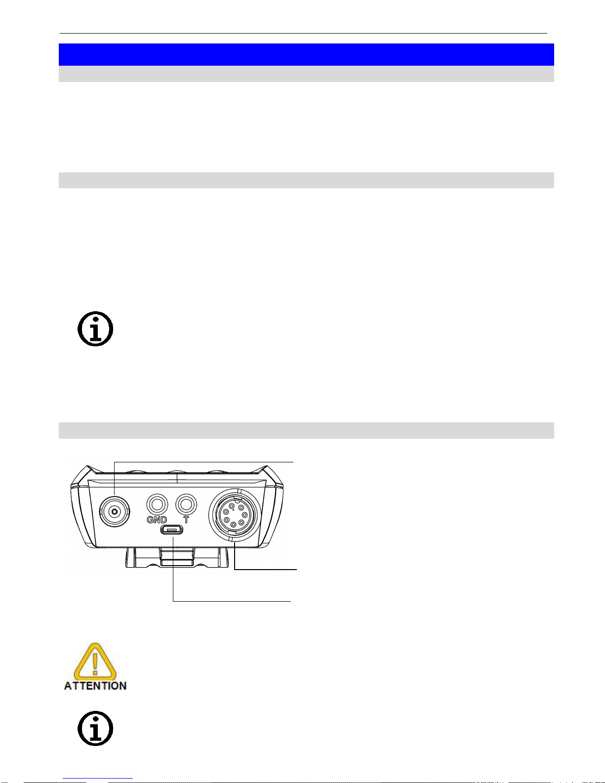
3.3 Connections
Front view
Connector
Probetype (standard)
BNC
pH (GE 125)
Banana
6 mm
(GND)
Resistive temperature probe
(PT 1000 or NTC 10 k)
common, needed only for
separate temperature probe
Banana
6 mm (T)
Resistive temperature probe
(GE 125 banana plug)
7-pol. LTW
Oxygen (GWO 5610) or
conductivity (LF 425)
Micro USB
For power supply or device
communication
Waterproofness is only guaranteed for plug connections in the
plugged-in state in combination with waterproof cable plugs.
The temperature measurement can be influenced by conductive
liquids on the banana sockets. We recommend always keeping the
connections dry.
Page 8
H87.0.0X.6C-01 Operating manual G 7500 Series page 8 of 34
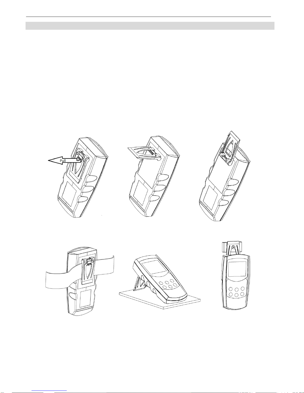
3.4 support and retaining clip
The stand is provided as a means to prop up or support the device in a stable
surface, for hanging on the wall or for attachment to a belt.
Instruction:
- Leave the stand collapsed in order to lay the product flat on a stable surface or
to hang it on a belt.
- Pull the grip labelled open in order to fold it out to a 90° angle. Now, the
product can be positioned on a stable surface.
- Pull the grip labelled open again in order to fold it out to a 180° angle. Now the
product can be hung.
- The product can be positioned ideally so that the display can always be read
clearly and easily depending on its use.
Pop-up clip closed
Pop-up clip at position 90°
Pop-up clip at position 180°
Device attached to a belt
Device set up on a table
Device suspended from
magnetic holder
GMH 1300
Page 9
H87.0.0X.6C-01 Operating manual G 7500 Series page 9 of 34
4 Operation
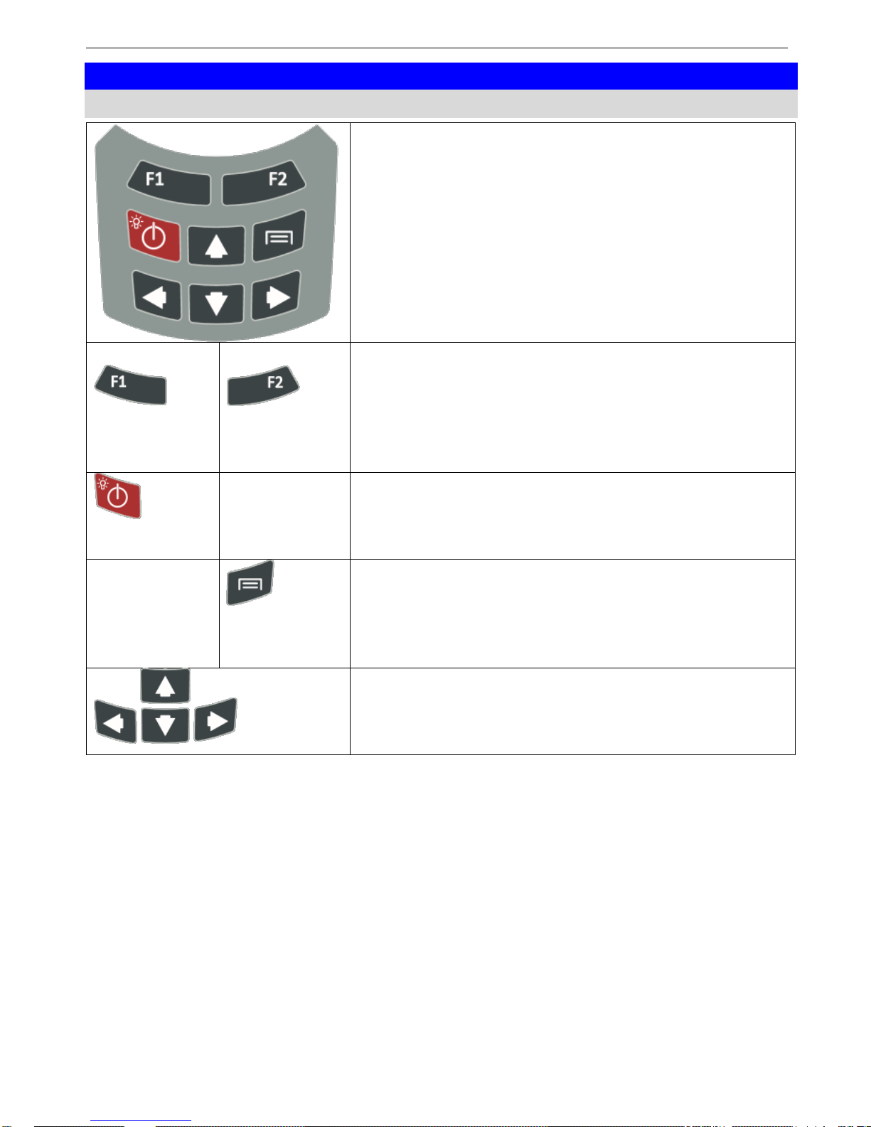
4.1 Keypad
With the keypad the device functions, display
mode, etc. can be set by user interaction.
The display will contain specific information for the
F1 and F2 soft-keys.
F1 and F2 soft-key
Depending to the device state (view, menu,
channel, …) the dark accentuated texts in the
display directly above the soft-keys are describing
the soft-keys function (e.g. ‘back’ for F1 and
‘change’ for F2).
power button
Will turn the device on (only when rechargeable
batteries are not empty) or off (only when the logger
is not running).
device settings
Will open the device-settings-menu.
Here anything that’s not related to a physical
measuring e.g. the date, time USB-mode and
language can be changed.
directional pad (up, down, right, left)
For navigation within a menu, for changing the
selected channel (up and down) or changing the
view (right and left).
Page 10
H87.0.0X.6C-01 Operating manual G 7500 Series page 10 of 34
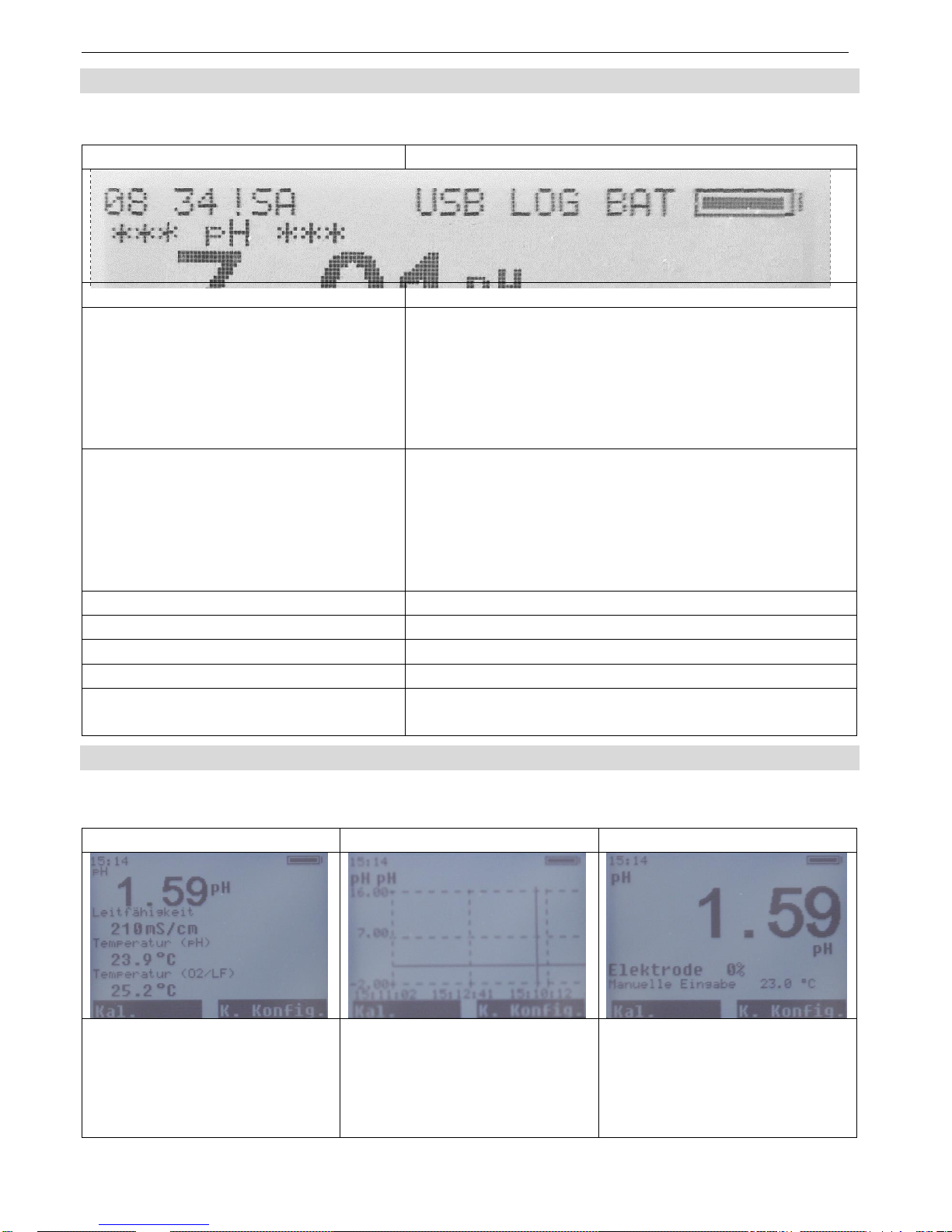
4.2 Status line
The status line is the first line in the display.
Display
Meaning
Current time
If time is flashing, time must be reseted
!
Internal memory error. When this error won’t
disappear after restarting the device, it should
be returned for repairing. The device will go to a
safe fallback mode were device settings are
stored and recalled from the mass storage
memory if this is available.
S
Saving to the internal mass storage memory
takes longer than intended. When the S will be
shown permanently in the display, please let
Windows check the mass storage device for
errors. When the S still shows up, the device
needs to be send back for repairing.
A
Alarm of a channel is active
USB
USB connection has been established.
LOG
Logger is active
BAT
Rechargeable battery capacity critically low
Battery indicator
If the battery capacity flashes, the battery is
being charged
4.3 Display elements
Views can be changed by the right and left keys of the directional pad. With the keys
up and down the channel can be changed.
Table view
Chart view
Large view
All channels in one row
Chart of one channel
Display of one channel
with specific parameters
(here: electrode quality
and temperature
compensation)
Page 11
H87.0.0X.6C-01 Operating manual G 7500 Series page 11 of 34
4.3.1 Menu
Depending on the selected channel, you can switch to the channel configuration
menu by pressing the function key F2. Here, channel-specific settings can be made.
5 Start operation
Charge the rechargeable batteries by connecting a power supply or the computer to
the micro USB connector.
Connect all desired probes or electrodes.
Turn on the device by pressing the power button.
Change date, time and language by pressing the device settings key and save the
changes made.
6 Basics of the measurement
At first the basics of all measurements will be depicted. Some channel specific
settings depend on these basics.
6.1 pH measurement
The pH value describes the acidic or alkaline behavior of an aqueous solution.
pH values below 7 are acidic (smaller values indicate higher acidity), and values
above 7 are alkaline; pH 7 = neutral.
The pH measurement is very precise, but also sensitive. The measured signals are
very weak (high-impedance), especially when measured in weak or low-ion media.
Therefore, always take measures to
To determine the pH value of a solution, its temperature needs to be
known. The reason is that most liquids change their pH value with the
temperature.
- avoid interference (electrostatic charges, etc.)
- keep plug contacts clean and dry
- prevent electrodes (except special waterproof versions) from extended
immersion above the shaft
- calibrate the electrode at sufficient intervals (see below). The frequency of
calibration can range from every hour to several weeks, depending on the
electrode and the application.
- use a suitable electrode. See chapter Fehler! Verweisquelle konnte nicht
gefunden werden.
Page 12

H87.0.0X.6C-01 Operating manual G 7500 Series page 12 of 34
6.1.1 Design
1. Coaxial cable
2. Reference electrode
3. Measuring electrode
4. Refill opening
5. Electrolyte
6. Internal buffer
7. Diaphragm
8. Glass membrane / source layer
The diaphragm, which establishes a connection between the electrolyte and the liquid
to be measured, can be designed in different ways. Clogging or soiling of the
diaphragm is a frequent cause of a malfunctioning or sluggish electrode. Always
handle the glass membrane with extreme care. The so-called source layer forms
there. This is crucial for the measurement and must always be kept moist.
There are also electrodes with integrated temperature sensors.
6.1.2 pH electrode
Normally, so-called pH single-rod measuring chains are used. They
include all necessary components that are integrated in an electrode.
Page 13

H87.0.0X.6C-01 Operating manual G 7500 Series page 13 of 34
6.1.3 Further information
pH electrode is a wear part. If the signal is very slow or the required values are no
longer observed after careful cleaning and possible regeneration, the electrode must
be replaced. When using the electrodes, be aware that various substances in
aqueous solutions can corrode glass and that chemicals can produce a chemical
reaction with the KCl solution in the electrode, which can result in blockage of the
diaphragm.
Examples:
In solutions that contain proteins, such as for measurements in medical and
biological applications, KCl can cause denaturation of the protein.
Coagulated paints
Solutions that contain high concentrations of silver ions
Substances that accumulate on the glass membrane or the diaphragm affect the
measurement and must be removed regularly. This can be achieved for example
with automatic cleaning systems.
6.1.4 Choosing a pH electrode
GE 100 BNC is a universal electrode with two ceramic diaphragms and liquid
GE 101 BNC is preferably used for small sample amounts. It comprises a glass
electrode with two ceramic diaphragms and liquid electrolyte.
GE 104 BNC is preferably used for measurements in low-ionic media, such as
rainwater, aquarium water and deionised water.
GE 114 WD is a universally applicable, durable and low-maintenance gel
electrode with Pellon diaphragm. It can be used for measurements in drinking
water, swimming pools, aquaria and slightly contaminated waste water.
GE 117 BNC is a temperature-compensated gel electrode with two ceramic
diaphragms and PH 13.5 cable screw coupling.
GE 120 BNC is an insertion electrode and is preferably used for measurements
in cheese, fruit and meat. For measurements in products containing proteins,
the electrode must be cleaned with a special cleaner. For this purpose, we
recommend the GRL 100 pepsin cleaning solution.
GE 125 BNC is a waterproof, universally applicable, durable and low-
maintenance gel electrode with ceramic diaphragm. It can be immersed above
the shaft for an extended time.
GE 151 BNC is a glass electrode and is preferably used in galvanic
applications for paints and lacquers.
GE 173 BNC is an alkaline-resistant glass electrode with ground diaphragm
and gel electrolyte for chemical and waste water applications.
Page 14

H87.0.0X.6C-01 Operating manual G 7500 Series page 14 of 34
6.1.5 Service life
The service life of electrodes is normally at least 8 to 10 months. When
cared for properly, this can usually increase to more than 2 years. The
actual life will vary depending on the particular application.
6.1.6 Care and maintenance
The GAK 1400 working and calibration set includes all necessary
products for calibration, care and maintenance of the electrode.
Normal cleaning takes place with the GRL 100 pepsin cleaning
solution into which the electrode is immersed for 5 minutes before
being rinsed off with clean water.
Crystallization of the 3 mol/l KCL solution is unavoidable. Crystallized
potassium chloride on the protective cap and shaft can easily be
removed with a fingernail or cloth and is therefore does not constitute
a defect or cause for complaint.
Dirty electrodes must be cleaned. The suitable cleaning agents for the pH glass
membrane are listed in the table below.
Impurities
Cleaners
General residue
Mild detergent
Inorganic coatings
1 mol/l HCl solution or GRL 100 pepsin
cleaning solution
Metal compounds
1 mol/l HCl solution or GRL 100 pepsin
cleaning solution
Oil and grease
Special cleaner or solvent
Biological coatings with protein
1% pepsin enzyme in 0.1 molar GRL 100
HCl solution
Biological coatings with protein
Acetone
Extremely resistant residues
Hydrogen peroxide or sodium hypochloride
The material of the pH probe must always be protected. Plastic shafts must not be
cleaned in solvents, etc. If in doubt, contact the manufacturer to inquire about suitable
cleaners for the existing electrode. This is also important in the case of aggressive
substances or other substances that are not primarily water-based!
Page 15

H87.0.0X.6C-01 Operating manual G 7500 Series page 15 of 34
6.2 Basics about conductivity
Definition of conductivity :
The ability of a material to conduct electric current:
l: length of the material
A: diameter
R: measured resistance
Unit
, common for liquids:
and
The conductivity is the reciprocal value of the resistivity.
(The conductance is the reciprocal value of the measured resistance R)
6.3 Conductivity measurement
The conductivity measurement is a rather uncomplicated measurement. The
standard measuring cells are stable for a long time if used correctly and can be
adjusted by slope correction.
Range
1 2 3
4
45..500 mS/cm
5.0..50.0
mS/cm
500..5000
µS/cm
0.0..500.0
µS/cm
Within the integrated automatic range selection, the range with the best resolution is
automatically selected.
6.4 Electrodes / measuring cells
6.4.1 Design and selection
Basically there are two types of measuring cells: 2-pole and 4-pole cells. The
operation is done similarly; the 4-pole measuring cells can compensate polarization
effects and – up to some degree – soiling due to its complex measuring method.
2-pole measuring cell
4-pole measuring cell
6.4.2 Calibration / Adjustment of measuring cells
Especially in harsh environments and over long time the cell constants of measuring
cells are drifting. Depending on the application and usage we recommend a regular
checking of the precision of the measuring chain: instrument + cell. For this there are
control solutions available (GKL 100, 101, 102). At normal usage a checking each
half year is recommended.
Page 16

H87.0.0X.6C-01 Operating manual G 7500 Series page 16 of 34
6.5 Temperature compensation
The conductivity of aqueous solutions depends on its temperature. The temperature
dependency is strongly dependent on the type of solution. The temperature
compensation recalculates solutions’ conductivity to a consistent reference
temperature. The most common reference temperature is 25 °C, but 20 °C can also
be selected.
6.5.1 Temperature compensation “NLF” according to EN 27888
For most applications (e.g. in the area of fish farming, surface or drinking water
measurements, etc.) the non-linear temperature compensation for natural water
(“nLF”, according to EN 27888) is sufficiently accurate.
Recommended application range of nLF-compensation: between 60 µS/cm and 1000
µS/cm.
6.5.2 Linear temperature compensation
If the actual function needed for exact temperature compensation is not known,
“linear temperature compensation” is normally selected (Menu, t.Cor = Lin, t.Lin
corresponds
), i.e. one assumes that the actual temperature dependency at the
considered concentration range is approximately equal:
Temperature coefficient of about 2.0 %/K are most common.
A temperature coefficient can be determined for example by measuring a solution
with deactivated temperature compensation at two different temperatures (T1 and
T2).
TK
lin
is the value input at the menu
LF
T1
conductivity at temperature T1
LFT2 conductivity at temperature T2
Page 17

H87.0.0X.6C-01 Operating manual G 7500 Series page 17 of 34
6.6 Design of the sensor GWO 5610
6.6.1 General
The oxygen sensor is an active sensor. It consists of a platinum cathode, a lead
anode and potassium hydroxide (KOH) as an electrolyte. If oxygen is present, it is
reduced on the platinum cathode and the sensor delivers a signal. If no oxygen is
present, no signal is delivered. The anode is consumed by the oxygen measurement.
The sensor ages. Furthermore, the sensor loses water through the permeable
membrane, in particular, when it is stored in dry air. Therefore, it should be checked
and maintained regularly and replaced as necessary.
The electrode contains potassium hydroxide. This causes burns. All
contact with the skin, clothing and eyes should be avoided.
Nevertheless, should contact occur, take the following measures.
Eyes: Flush with flowing water for at least 15 minutes, seek medical
attention!
Consult a doctor.
Always store oxygen sensor GWO 5610 wet!
- In a storage bottle filled with water or
- place in a container with water.
After prolonged storage before the measurement, clean the membrane
with a soft paper towel of possible coverings (algae, bacteria, ...).
6.6.2 Design
Shaft
Membrane
Refill opening
Storage bottle
Platinum electrode
Page 18

H87.0.0X.6C-01 Operating manual G 7500 Series page 18 of 34
Platinum electrode
If oxygen is present, it is reduced on the platinum electrode and the sensor delivers a
signal. Soiling on the platinum electrode or between the membrane and electrode can
influence the measurement.
Storage bottle
The storage bottle is provided to keep the membrane moist. The service life of the
sensor is extended as a result. Distilled or deionized water is in the storage bottle; do
not add any other liquids!
Membrane head
The membrane head is covered with a thin plastic membrane. Faulty measurements
will occur if the membrane is damaged or there are large air bubbles or even an air
bubble ring on the membrane. This can also be the cause if a sensor can no longer
be calibrated. The GWOK 02 membrane head is a spare part and can be re-ordered
separately.
Refill opening
Electrolyte must be filled or added for the initial commissioning of a sensor which is
delivered dry, when performing maintenance or after use at high temperatures.
6.6.3 Service life
The sensor signal deteriorates relatively quickly at the end of the service life of the
sensors. The electrode evaluation in %, therefore, can only be used as a guide value.
A value of 70% does not mean that exactly 70% of the service life is still available,
rather that the electrode signal has 70% of a comparison signal.
The sensor evaluation is updated by the measuring device after a
successfully performed calibration of the oxygen sensor.
The nominal service life can be reduced significantly due to use. Influential factors
include:
▪ Storage / operating temperature
▪ Contamination of the measured water
▪ Mechanical stress of the sensor membrane
▪ Storage in dry air
▪ Continuous use in elevated carbon dioxide concentrations
6.6.4 Operating position
The oxygen sensor should be arranged vertically upwards with the connecting cable.
A slight angle of inclination does not impair the measurement.
Page 19

H87.0.0X.6C-01 Operating manual G 7500 Series page 19 of 34
6.6.5 Measurement accuracy
The measurement accuracy can be impaired by:
▪ An inadequate flow below the necessary value of approx. 30cm/sec.
▪ The water temperature and sensor temperature must be the same. The most
accurate measurements are provided when the measuring temperature is
calibrated.
6.6.6 Visible residues inside the membrane cap
As a reaction product, lead oxides (brown or red, from reaction with oxygen) and lead
carbonate (white, from reaction with carbon dioxide) are created during operation on
the lead anode. These substances can collect on the membrane, but they do not
usually affect the measurement function. Most of these substances can be removed
during the maintenance of the sensor.
Prior to screwing on the membrane cap, they should be removed as far as possible in
order to prevent particles from being trapped between the membrane and the
platinum cup. A rapid or excessive formation of lead carbonate after commissioning is
an indication of air in the sensor. This is usually due to incomplete filling or a leak due
to improper fitting of the cap / fill screw or membrane leak.
6.7 Commissioning / filling of the sensor GWO 5610
The electrode contains potassium hydroxide. This causes burns. All
contact with the skin, clothing and eyes should be avoided.
Nevertheless, should contact occur, take the following measures.
a) Eyes: Flush with flowing water for at least 15 minutes, seek medical
attention!
b) Skin: Wash with large amounts of water for several minutes!
c) Clothing: Remove immediately!
d) If swallowed: Drink large amounts of water, do not induce vomiting
and seek medical attention!
Protective goggles must be worn for all of the following activities!
Protective gloves must be worn for all of the following activities!
The sensor is delivered dry. Therefore, the sensor is well-suited for storage. The
sensor must be filled in good time before the measurement. A wait time of approx. 2
hours after filling should be planned in order to allow the sensor to stabilize.
Page 20

H87.0.0X.6C-01 Operating manual G 7500 Series page 20 of 34
6.8 Sensor GWO 5610 maintenance
After every calibration the sensor quality in % will be shown in the large digit display.
When the quality is below 25 % the sensor should be maintained.
Attention! The electrolyte is corrosive.
To maintain electrode please proceed as follows:
1. Unscrew diaphragm head and wipe clean of electrolyte solution using a paper
cloth. Do not touch electrolyte. If your skin had contact with electrolyte,
immediately rinse thoroughly with clear water.
2. Clean silver cathode with sand paper (grain size 240). Do not polish silver
cathode, surface should stay rough. Remove all dust.
3. Remove filling screw and top up lost electrolyte (e.g. using disposable syringe))
4. Put back and tighten filling screw.
5. Top up diaphragm head with electrolyte avoiding air bubbles and place on table
(cover table with absorbent paper first).
6. Keep electrode in a vertical position and screw diaphragm head to the electrode
from the bottom. Electrolyte will be forced out of the diaphragm head and spill
over (put on disposable gloves or use paper towel to touch diaphragm head).
7. Wipe up excess electrolyte with paper cloth.
8. Check cathode for air bubbles.
If there are large air bubbles, remove diaphragm head again and repeat process
as of point 5. If O-ring has been damaged, it has to be replaced.
When maintenance has been completed plug on protective flask. Re-connect
electrode to measuring device and wait for at least 3 hours till electrode can be
calibrated.
Page 21

H87.0.0X.6C-01 Operating manual G 7500 Series page 21 of 34
6.9 Basics about oxygen measuring
Please observe the following points when measuring dissolved oxygen:
- For measuring remove the protective flask.
- Do not disconnect electrode from device.
If electrode has been disconnected, wait 2..3 hours till the final electrode
signal has settled
before carrying out measurements or a calibration.
- Electrode needs to be calibrated (p.r.t. 'How to calibrate oxygen electrode')
- The temperatures of the electrode and of the liquid to be measured have
to be identical
(if necessary, wait till temperatures match)
- The Electrode has to be submerged at least 3 cm into the liquid to being
measured
- The measured liquid has to stream along the electrode membrane with
at least 30 cm/sec
for measurements to be sufficiently accurate: either stir continuously or
use agitator.
- The electrode measurement is sensitive against shocks!
By stirring of the electrode in the measured liquid be careful that the
electrode does not hit the
container. A vibration of the electrode has a effect to the measured value.
-The optimum operation position is: with the sensor inlet pointing downwards
The instrument calculates the oxygen concentration [mg/l], the oxygen saturation [%]
from the electrode signal and the temperature. According to DIN38408-C22 all
measurements refer to steam saturated air.
6.10 Ambient pressure and measuring depth of the electrode
The pressure at the sensor membrane is important for:
The calculation of the oxygen saturation (%sat).
At air water can get 100% saturation. Assumed that there are no oxygen
consuming processes (biological degradation, chemical effects) and that there
are no oxygen enriching processes (e.g. excessive ventilation or
photosynthesis)
The calculation of oxygen concentration (mg/l or ppm)
The electrode evaluation at calibration
Therefore it is necessary to compensate the pressure influence via integrated sensor
or, like practiced with more primitive instruments via tables and manual input of
pressure or Elevation above sea level values.
6.11 Correction of salinity
The higher the salinity (salt content) the lower the solubility of oxygen in water, i.e.
although the partial oxygen pressure is the same, the quantity of oxygen dissolved in
water (mg/l) is lower. Therefore, determination of the oxygen concentration requires
entering the salinity of the medium (p.r.t. 'Configuration'). The correction of salinity is
based on media on a water basis, whose chemical content is similar to sea water.
The corrections are based on the 'International Oceanographic Tables' (IOT).
Page 22

H87.0.0X.6C-01 Operating manual G 7500 Series page 22 of 34
7 Configuration
There are various configuration parameters available depending on the
product version and configuration. They can differ depending on the
product version and configuration.
In order to configure the product, you must first open the device settings menu. The
menu is opened as shown in the illustration. Prerequisite, The product is switched on.
1. Press the menu key for 1 second, to open the device settings menu.
2. The device settings menu appears in the display. The first parameter is shown.
3. By briefly pressing the Up button and the Down button, you can scroll through
the parameters. Select the parameter you would like to configure.
4. When you have selected the desired parameter, select them with the function
button F2. You can change the parameter to the desired value.
5. With the function button F1 you leave the device settings menu. The main
display is shown.
Representation:
Call up menu
Next
parameter
Change
parameter
Change value
Save changes
1 s
7.1 Device menu
<-- -->
<--
time and date
USB-mode
mass storage
COM port
logging time
logging
not activated
cyclic
on keypress
logging time
location
list 20 location names with up to 21
ASCII characters
language
German
English
backlight
auto-off
off
on
brightness
alarm activity
off
sound
blink
sound and blink
pH channels
inactive
Page 23

H87.0.0X.6C-01 Operating manual G 7500 Series page 23 of 34
active
O2/cond. channels
inactive
active
7.1.1 time and date
Here time and date can be set. The time is shown on the left in the upper status line.
When the time blinks, the time is invalid.
Depending on the language different time-zones are used. In German
MESZ/MEZ (automatic setting of daylight saving time) is used, in all
other languages UTC is used.
All time bases in terminal or data logging files are in UTC to ensure
trouble-free data exchange.
7.1.2 USB-mode
7.1.2.1 mass storage
In USB mass storage the device can no longer access the internal memory. The
logger can no longer be started. Accessing the internal mass storage memory can be
done without driver installation. Logger data can be copied or deleted.
The logger data are stored into a CSV file.
The location depends on the starting time of the logger.
Example: Logger was started 31st December 2020 at 19:11. The CSV files are then
located in the folder \DATA\20201231\1911\ .
Single shot logger data is always stored inside the \HISTORY\ directory.
Calibration data are stored like logger data, but inside the \CAL_DATA directory.
7.1.2.2 COM port
In this mode the computer can directly communicate with the device after driver
(windows only) installation. (115200 8N1 \r\n as end marking)
The following commands are supported:
GetChannelMenu: #
menu output with all settings
GetLastValue: #
output of the last measured value
GetCalibrationReport: #
displays the last calibration values
DeviceInformation: 0
device and license information
AddLocationDescription: ##
changes the location description of location ##
# is the channel number starting from 0.
Nr.
channel
Data name (Prefix)
0
oxygen
O2
1
pH
PH
2
conductivity
COND
3
temperature (pH)
T_PH
4
temperature (O2/LF)
T_COND
5
air pressure
PRES
6
device menu (value = battery capacity in %)
DEV
7.1.3 alarm activity
The alarm activity means what action should be done when an alarm (of any channel)
is active. The alarm activity will happen only when a channel’s alarm condition is true,
Page 24

H87.0.0X.6C-01 Operating manual G 7500 Series page 24 of 34
the channel is active and the alarm function is activated. The device will show ‘A’ in
the status line, even if the alarm activity is off.
7.1.4 logger
Three different functionalities can be set
not activated
cyclic
on keypress
7.1.4.1 not activated
The logger is not active, USB settings an channel calibration can be used.
7.1.4.2 cyclic
When the logger started, each channel will be recorded. The logging interval is in
seconds. On record start, a new folder will be created in the mass storage memory
(e.g. the logger was started 31st December 2020 at 19:11, a folder
\DATA\20201231\1911\ will be created). In this folder the channel settings (JSN file)
and the measured values (CSV file) are stored.
When the logger is set to on, channel settings can no longer be changed or
calibration can no longer be performed. The device can no longer be turned off by the
on/off button, instead the device menu will be shown.
To start the logger in the normal display the F1-key will be entitled with “start”.
When the logger is running, the F1-key will be entitled with “stop” and can be stopped
by pressing the F1-key.
7.1.4.3 on keypress
With “on keypress” one measuring will be added to the files inside the HISTORY
directory. A location is also stored to this dataset, this can be selected from a list.
The location description can be set via COM port interface command (see above).
The location description must only contain ASCII-letters and numbers, no special
characters. Up to 22 letters can be used for the location description. The maximum
length of the location list is 20 entries.
The description text can also be changed directly in mass storage device. The folder
LOCATION contains 20 *.LOC files that can be changed with every text editor. After
changing the device must be restarted to read in the files.
In display mode the F1-key will be entitled with “logger”, on each keypress of the F1key one dataset is stored. During the saving progress the F1-key will be entitled with
“wait…”
7.1.5 pH channels and O2/cond. channels
When set to ‘inactive’ all depending channels are turned off.
All these channels will no longer be shown in the display.
In any logger recording an error message will be stored for inactive channels. Only
one of these options can be set to ‘inactive’.
Page 25

H87.0.0X.6C-01 Operating manual G 7500 Series page 25 of 34
7.2 pH channel menu
<-- -->
<--
measurement
pH
voltage
Voltage (H)
alarm
function
off
on
min.-limit
max.-limit
temp.
compensation
ATC
off
on
reference channel
banana sockets
O2/cond. electrode
pH probe
buffer
GMH standard
DIN standard
no detection
calibration mode
standard
strict
fast
7.2.1 temperature compensation
7.2.1.1 ATC
The automatic temperature compensation (ATC) can be switched on or off.
When deactivated, the temperature has to be set manually.
When activated the temperature is measured from the reference channel.
7.2.2 reference channel
Here the cannel for the ATC can be selected.
7.2.2.1 banana sockets
Reference temperature measured from RTD on banana sockets.
With a pH electrode with internal RTD only socket T is connected (common GND with
BNC connector).
With an external RTD probe both sockets are used (as it’s an RTD sensor, T or GND
have no polarity).
7.2.2.2 O2/cond. electrode
Reference temperature measured from oxygen or conductivity electrode. Inside the
electrode is an integrated RTD sensor. The electrode needs to be inside the same
fluid as the pH electrode. According to the size of the oxygen or conductivity
electrode, the integrated RTD sensor is very slow.
Page 26

H87.0.0X.6C-01 Operating manual G 7500 Series page 26 of 34
7.2.3 buffer
The buffers are auto detected. When the buffer is not recognized (no PHL or DIN
buffer, very bad electrode, extreme temperature or contaminated buffer solution) the
device will ask for manual input of pH value and temperature.
On manual input and using oft he listed standard buffers, please check the electrode
quality after calibration. If in doubt prepare new buffer solutions and clean or replace
the electrode. At extreme temperatures, try to bring them to room temperature (20..25
°C).
7.2.3.1 PHL standard
For calibration the standard buffers for the GMH handheld instruments are used.
These are pH 4 (red), pH 7 (green) und pH 10 (blue).
7.2.3.2 DIN standard
For calibration DIN standard buffers are used.
pH 1,680
pH 3,557
pH 3,776
pH 4,001
pH 6,881
pH 7,429
pH 9,225
pH 10,062
7.2.3.3 No detection
Device will ask for manual buffer input after detecting a stable value within the valid
temperature range.
7.2.4 calibration mode
This setting has strong influence about the accuracy and duration of the calibration
process.
7.2.4.1 standard
allowed deviance 0,075 mV between last 45 measurements
7.2.4.2 strict
allowed deviance 0,075 mV between 45 measurements and allowed deviance 0,01
mV between last 10 measurements
7.2.4.3 fast
allowed deviance 0,23 mV between last 10 measurements
Page 27

H87.0.0X.6C-01 Operating manual G 7500 Series page 27 of 34
7.3 temperature channel menu
Independent available for both, temperature (O2/LF) and temperature (pH)
sensortype
NTC 10 k
NTC 10 k only
available for O2/LF
Pt1000
unit
°C
°F
K
alarm
function
off on
min.-limit
max.-limit
7.3.1 sensortype
The channel temperature (O2/LF) will change the sensortype automatically when an
electrode is changed.
Conductivity electrode (LF 425) sensortype: Pt1000
Oxygen electrode (GWO 5610) sensortype: NTC 10 k
When other electrodes are used, the setting has to be changed manually.
Pt1000 is normally the correct setting for temperature (pH) as it’s standard electrode is
the GE 125.
When using different electrodes, check the manual of the electrode for the correct
setting.
7.4 oxygen channel menu
measurement
O2 concentration
[mg/l]
O2 saturation
[%]
O2 partial pressure
[hPa]
alarm
function
off on
min.-limit
max.-limit
salinity
auto pressure
comp.
off
on
absolute pressure
7.4.1 salinity
Input of salinity. The oxygen value will be re-calculated on values not equal to 0.
7.4.2 auto pressure comp.
Automatic pressure compensation or manual input.
7.4.3 absolute pressure
Manual input of the air pressure.
Page 28

H87.0.0X.6C-01 Operating manual G 7500 Series page 28 of 34
7.5 conductivity channel menu
measurement
conductivity
salinity
alarm
function
off
on
min.-limit
max.-limit
cell factor
auto-range
off
on
range
temp compensation
off
NLF
linear
lin. coefficient
reference
temperature
T=25 °C
T=20 °C
7.5.1 cell factor
Manual input of the cell factor. G 7500 sets with conductivity electrode are
preconfigured with the electrode’s cell factor.
7.5.2 auto-range
Automatic range selection of the conductivity measurement is active.
auto-range: 0 µS/cm..500 mS/cm
7.5.3 range
Manual range selection when auto-range is not active.
45..500 mS (range: 1)
5,0..50,0 mS (range: 2)
5..5 000 µS/cm (range: 3)
0,0..500,0 µS/cm (range: 4)
7.5.4 linearization
Linearization of the measured value according to nlF or manual input.
7.5.5 lin. coefficient
Manual linearization coefficient (only with linearization is linear input).
7.5.6 reference temperature
Reference temperature of the measured conductivity.
Page 29

H87.0.0X.6C-01 Operating manual G 7500 Series page 29 of 34
8 Error codes (in dataset)
While logging data or querying values via interface, the error codes will not be shown
as human readable text. This is because the relation between error and error
message would get lost between different languages.
Error code
Text
Hint
0
OK
no error
100000000
measuring range overrun
check calibration and sensor
100000001
measuring range underrun
check calibration and sensor
100000010
calculation failed
check settings
100000011
system error
restart device*
100000012
battery empty
recharge device
100000013
no sensor
connect sensor
100000014
recording error
restart device*
100000015
EEPROM checksum wrong
restart device*
100000016
system restarted
device is restarting, wait shortly
100000017
data pointer error
restart device*
100000018
data invalid
restart device*
100000020
recording stopped
logger has been stopped
100000021
recording started
logger has been started
100000022
channel deactivated
channel is deactivated via device
settings
100000023
temp. channel deactivated
check temperature compensation
settings,
activate O2/cond. channel
100000024
no temp. sensor
plug in temperature sensor check
temperature compensation
settings,
activate O2/cond. channel
100000025
no data available
device has not measured anything
-23
sensor module not responding
restart device*
-10
not existing
restart device*
-255
unexpected error
restart device*
-100
calibration error
try to calibrate again
-75
not found
restart device*
-101
not calibrated
perform a calibration
-253
Value not stable
Ensure a stable environment
-251
Not in the temperature range
Check temperature
*Resend device for service, when the error does not disappear
Page 30

H87.0.0X.6C-01 Operating manual G 7500 Series page 30 of 34
9 Calibration
9.1 General information
Each channel that supports a calibration will show cal. Above the F1-key.
The Calibration will only be available when the logger is set to “not active”.
When you press the F1-key the calibration wizard will guide you through the
calibration steps. Depending on the channel you will need to have buffer solutions
prepared.
More point calibration can be done (if supported from the measuring channel) after
the 1st calibration point is finished. You don’t need to select how many points should
be calibrated and you don’t need to follow a predefined order of buffer values, you
can just use them in random order.
9.2 pH calibration
Required Accessories:
Buffer solutions (e.g. the PHL buffer solutions with ph 4, ph 7 and ph 10)
deionized water for cleaning between changing buffer solutions
If necessary, liquid thermometers to determine the temperature of the buffer solutions
(if no GE 125 or similar is used)
Start the calibration process, see above.
Follow the instructions of the device:
Clean the electrode and immerse it in the first buffer solution.
After the buffer solution has been determined, continue with the next buffer solution
or complete the calibration.
A certain sequence of buffer solutions is not specified.
If no temperature reference is present, the temperature of the buffer solution must
also be determined with another measuring instrument and entered.
The electrode evaluation after completion of the calibration process informs about the
state of the electrode.
9.3 O2 calibration
Required Accessories:
GCAL 3610 calibration vessel for oxygen sensor, alternatively use a moist cloth.
deionized water for cleaning the sensor.
Start the calibration process, see above.
Follow the instructions of the device:
Clean the sensor and plug it into GCAL 3610.
Alternatively, wrap the sensor loosely into a moist cloth.
The sensor evaluation after completion of the calibration process informs about the
state of the sensor.
Page 31

H87.0.0X.6C-01 Operating manual G 7500 Series page 31 of 34
10 Calibration and adjustment service
The certificates are categorised as ISO calibration certificates and DAkkS calibration
certificates. The purpose of the calibration is to verify the precision of the measuring
device by comparing it with a traceable reference.
The ISO standard 9001 is applied for the calibration certificates. These
certificates area affordable alternative to the DAkkS calibration
certificates and provide information of the traceable reference, a list of
individual values and documentation.
The DAkkS calibration is based on DIN EN ISO/17025, the
accreditation basis recognised worldwide. These certificates offer highquality calibration and consistently high quality. DAkkS calibration
certificates can only be issued by accredited calibration laboratories
which have demonstrated their expertise in accordance with DIN EN
ISO/IEC 17025. The ISO calibration includes any necessary
adjustment with the purpose of minimising a deviation of the measuring
device.
DAkkS calibration certificates are accompanied with a list of individual
measurements before and after the adjustment, documentation and, if
applicable, graphic representation, calculation of the expanded
measuring uncertainty and traceability to the national standard.
The product is delivered with a test report. This confirms that the
measuring device has been adjusted and tested.
Only the manufacturer can check the basic settings and make
corrections if necessary.
11 Replacing rechargeable batteries
Using damaged or unsuitable batteries can generate heat, which can
cause the batteries to crack and possibly explode!
If the batteries have different charge levels, leaks and thus damage to
the product can occur.
- Use new, high-quality batteries!
- Do not use different types of batteries!
- Remove depleted batteries and dispose of them at a suitable
collection point!
Unnecessary screwing places the water-tightness of the product,
among other things, at risk and should be avoided.
Read the following handling instructions before replacing batteries and
follow them step by step. If disregarded, the product could be damaged
or the protection from moisture could be diminished.
Page 32

H87.0.0X.6C-01 Operating manual G 7500 Series page 32 of 34
Required tools: 1x Phillips screwdriver PH 1
Remove device from silicone cover.
Unscrew 3 screws on the device bottom. Carefully open the top cover and fold to
the right (see picture). The cover is attached to the PCB by a flexprint connector.
When ripping out the flexprint connector from the socket, the keypad will no
longer work and the device needs to be sent in for repairing.
Carefully change the 3
rechargeable Ni-MH batteries
(type AAA). Take care of the
polarity that is printed inside the
holder. The batteries have to slip
in without any force.
Check the sealing in top cover
must be clean and without any
damage.
Attach top cover and hand-tight
the screws. When tightened to
strong or to weak the sealing can
be affected.
Insert device into silicone cover.
12 Reshipment and disposal
12.1 Reshipment
All devices returned to the manufacturer have to be free of any residual
of measuring media and other hazardous substances.
Measuring residuals at housing or sensor may be a risk for persons or
environment
Use an adequate transport package for reshipment, especially for fully
functional devices. Please make sure that the device is protected in the
package by enough packing materials.
Add the completed reshipment form of the GHM website
https://www.ghm-group.de/infothek/#downloadcategory--8
12.2 Disposal
Dispense exhausted batteries at destined gathering places The device
must not be disposed in the unsorted municipal waste! Send the device
directly to us (sufficiently stamped), considering the above if it should be
disposed. We will dispose the device appropriate and environmentally
sound.
Private user can return the device at the municipal collection points for
small electrical appliances.
Page 33

H87.0.0X.6C-01 Operating manual G 7500 Series page 33 of 34
13 Specification
13.1 measurements and accuracy
pH
suggested probe
GE 125 (waterproof with Pt 1000 temperature probe)
connector
BNC-Buchse (waterproof)
pH
-2,00..+16,00 pH (+-0,25 % FS)
ORP
-2 000..+2 000 mV (+-0,25 % FS)
ORP (hydrogen referenced)
-1 775..+2 148 mV (+-0,25 % FS)
(for electrodes with 3 mol/l KCL electrolyte 0..100 °C)
temperature compensation
automatic or manual
Pt1000
(via banana connector or O2/conductivity probe)
accuracy requirements
Ta, Tm = 25 °C
dissolved oxygen
suggested probe
GWO 5610 (with NTC 10 k temperature probe)
connector
7-pol. LTW (waterproof)
oxygen saturation
0,0..500,0 % sat (+-1,5 % FS)
oxygen concentration
0,0..50,0 mg/l (+-1,5 % FS)
oxygen partial pressure
0..1 013 hPa (+-1,5 % FS)
temperature compensation
automatic: 0,0..+50,0 °C
salinity correction
off, 0..70 g/kg
accuracy requirements
Ta, Tm = 20 °C, 100 % sat. O2
direct flow > 20 cm/s
conductivity
suggested probe
LF 425 (with Pt 1000 temperature probe)
connector
7-pol. LTW (waterproof)
conductivity
auto-range: 0 µS/cm..500 mS/cm (+-0,5 % FS)
45..500 mS (Range: 1)
5,0..50,0 mS (Range: 2)
500..5 000 µS/cm (Range: 3)
0,0..500,0 µS/cm (Range: 4)
salinity
0,0..70,0 g/kg (+-0,5 % FS)
temperature compensation
automatic: -5,0..+100,0 °C
reference temperature
20 °C, 25 °C
linearization
off, manual linear input or non linear function for
natural water according to DIN EN27888 (ISO 7888)
accuracy requirements
Ta, Tm = 25 °C
temperature (banana plug)
sensor type
Pt 1000
Measuring range
Pt 1000: -10,0..+ 150,0 °C (+-0,25 % FS)
temperature (O2/LF electrode)
sensor type
Pt 1000 or NTC 10k
measuring range (Pt1000)
-10,0..+110,0 °C (+-1,0 % FS)
measuring range (NTC 10k)
-10,0..+110,0 °C (+-0,5 % FS)
Ta = ambient temperature, Tm = media temperature
Page 34

H87.0.0X.6C-01 Operating manual G 7500 Series page 34 of 34
GHM GROUP – Greisinger | GHM Messtechnik GmbH
Hans-Sachs-Str. 26 | 93128 Regenstauf | GERMANY
Phone +49 9402 9383-0 | Fax +49 9402 9383-33
www.greisinger.de | info@greisinger.de
13.2 general specification
data logger
internal mass storage (since 2018: 8 GB)
display
monochrome 180 x 128 px LC-Display
(white and red backlight)
primary power supply
3x AAA Ni-MH rechargeable batteries (750 mAh)
current consumption
approx. 75 mA in use, approx. 0,6 mA in standby
interface/supply
type
micro USB
USB mode
CDC (COM port, driver on mass storage)
MSC (mass storage, no driver needed)
DFU (firmware update, driver on mass storage)
USB current consumption
max. 500 mA (rechargeable batteries charging)
working condition
-25..+50 °C, 0..95 % r.F. (non condensing)
storage condition
-25..+70 °C
protection class
IP65 / IP67
housing
impact resistant ABS, with support and retaining clip
dimension
160 x 86 x 37 mm (H x B x T) incl. silicone cover
weight
approx. 300 g incl. rechargeable batteries
scope of supply
device, rechargeable batteries, micro USB cable and
short manual
14 Terms of license
14.1 FreeRTOS
Copyright (C) 2016 by Real Time Engineers Ltd.
All rights reserved
The source code is licensed under the MIT open source license.
The full text of the MIT open source license is available here:
https://www.freertos.org/a00114.html
14.2 FatFS
Copyright (C) 2017 by ChaN
All right reserved.
FatFs module is an open source software.
Redistribution and use of FatFs in source and binary forms, with or without
modification, are permitted provided that the following condition is met:
1. Redistributions of source code must retain the above copyright notice, this
condition and the following disclaimer.
This software is provided by the copyright holder and contributors “AS IS” and any
warranties related to this software are DISCLAIMED.
The copyright owner or contributors be NOT LIABLE for any damages caused by use
of this software.
 Loading...