

Page 1
Operating manual
G 1910-02
Compact CO2 monitor with alarm
EN
Page 2

Table of contents
2 / 30
B-H90.0.01.DB2-2.1
Table of contents
1 About this documentation .......................................................................................................................... 4
1.1 Foreword .......................................................................................................................................................... 4
1.2 Purpose of the document ............................................................................................................................... 4
1.3 Legal notices .................................................................................................................................................... 4
1.4 Correctness of content ................................................................................................................................... 4
1.5 Layout of this document ................................................................................................................................. 4
1.6 Further information .......................................................................................................................................... 5
2 Safety ............................................................................................................................................................... 6
2.1 Explanation of safety symbols ....................................................................................................................... 6
2.2 Foreseeable misuse ....................................................................................................................................... 6
2.3 Safety instructions ........................................................................................................................................... 7
2.4 Intended use .................................................................................................................................................... 8
2.5 Qualified personnel ......................................................................................................................................... 8
3 Description ..................................................................................................................................................... 9
3.1 Scope of delivery ............................................................................................................................................. 9
3.2 Functional description..................................................................................................................................... 9
4 The product at a glance ............................................................................................................................. 10
4.1 The G 1910-02 .............................................................................................................................................. 10
4.2 Display elements ........................................................................................................................................... 10
4.3 Operating elements....................................................................................................................................... 10
4.4 Connections ................................................................................................................................................... 11
5 Operation ...................................................................................................................................................... 12
5.1 Commissioning .............................................................................................................................................. 12
5.1.1 Explanation ......................................................................................................................................... 12
5.2 Configuration.................................................................................................................................................. 12
5.2.1 Explanation ......................................................................................................................................... 12
5.2.2 Opening the configuration menu .................................................................................................... 12
5.2.3 Configuring parameters of the configuration menu ..................................................................... 13
5.2.4 Call-up of the expanded settings menu .......................................................................................... 15
5.2.5 Configure parameters of the expanded settings menu ................................................................ 16
6 Measurement Basics .................................................................................................................................. 18
6.1 NDIR CO2 sensor .......................................................................................................................................... 18
6.1.1 Explanation ......................................................................................................................................... 18
6.1.2 Design.................................................................................................................................................. 18
7 Operation and maintenance ..................................................................................................................... 19
7.1 Operating and maintenance notices .......................................................................................................... 19
7.2 Battery ............................................................................................................................................................. 19
7.2.1 Charge status display ........................................................................................................................ 19
7.2.2 Charging the batteries ....................................................................................................................... 19
7.2.3 Rechargeable battery replacement .................................................................................................. 20
7.3 CO2 adjustment ............................................................................................................................................. 21
8 Error and system messages .................................................................................................................... 24
9 Disposal ......................................................................................................................................................... 26
10 Technical data .............................................................................................................................................. 27
11 Spare parts and accessories ................................................................................................................... 28
Page 3

Table of contents
B-H90.0.01.DB2-2.1
3 / 30
12 Service ........................................................................................................................................................... 29
12.1 Manufacturer .................................................................................................................................................. 29
12.2 Repairs processing ........................................................................................................................................ 29
12.3 Sales offices ................................................................................................................................................... 29
Page 4

1 | About this documentation
G 1910-02
4 / 30
B-H90.0.01.DB2-2.1
1 About this documentation
1.1 Foreword
Read this document carefully and familiarise yourself with the operation of the product
before you use it. Keep this document ready to hand and in the immediate vicinity of
the product so that it is available to the personnel/user for reference at all times in
case of doubt.
The product was developed according to the state of the art and fulfils the requirements of the applicable European and national Directives. All corresponding documents are available from the manufacturer.
Only technically qualified persons are permitted to carry out commissioning, operation,
maintenance and decommissioning. The qualified personnel must have carefully read
and understood the operating manual before beginning any work.
1.2 Purpose of the document
– It provides important information for operating safely and efficiently with the prod-
uct.
– In addition to the quick reference guide with all relevant legal and safety content in
hard copy, this document is a detailed reference option for the product.
1.3 Legal notices
The liability and warranty of the manufacturer for damages and consequential damages are voided with misuse, disregarding this document, disregarding safety notices,
assignment of inadequately qualified technical personnel and arbitrary modifications of
the product.
Only carry out the maintenance and service tasks on this product that are described in
this documentation. In the process, adhere to the specified steps. For your own safety,
only use original spare parts and accessories of the manufacturer. We assume no liability for the use of other products and resulting damage.
This document is entrusted to the recipient for personal use only. Any impermissible
transfer, duplication, translation into other languages or excerpts from this operating
manual are prohibited.
The manufacturer assumes no liability for print errors.
1.4 Correctness of content
The contents of this document were checked for corrected and are subject to a continuous correction and updating process. This does not rule out potential errors. In the
event that errors are discovered or in case of suggestions for improvement, please
inform us immediately via the indicated contact information in order to help us make
this document even more user-friendly.
1.5 Layout of this document
Description
Each chapter is explained at the beginning in the description.
Page 5

G 1910-02
About this documentation | 1
B-H90.0.01.DB2-2.1
5 / 30
Prerequisite
All mandatory prerequisites are then listed for each step.
Instruction
Tasks to be carried out by the personnel / user are represented as numbered instructions. Adhere to the sequence of the specified instructions.
Representation
Shows an illustrative instruction or a configuration of the product.
Formula
Some instructions include a formula for a general understanding of a configuration,
programming or a setting of the product.
Outcome of an action
Result, consequence or effect of an instruction.
Emphases
In order to simplify legibility and provide a clearer overview, various sections / information are emphasised.
– 1234 Display elements
– Mechanical controls
– Product functions
– Product labels
– Cross-reference [ 4]
– Foot notes
1.6 Further information
Software version of the product:
– V1.6 or later
Page 6
2 | Safety
G 1910-02
6 / 30
B-H90.0.01.DB2-2.1
2 Safety
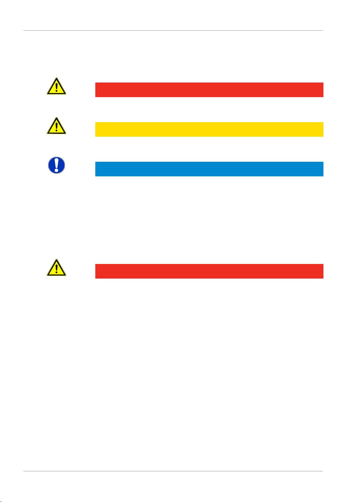
2.1 Explanation of safety symbols
DANGER
This symbol warns of imminent danger, which can result in death, severe bodily injury,
or severe property damage in case of non-observance.
CAUTION
This symbol warns of potential dangers or harmful situations, which can cause damage to the device or to the environment in case of non-observance.
NOTE
This symbol indicates processes, which can have a direct influence on operation or
can trigger an unforeseen reaction in case of non-observance.
2.2 Foreseeable misuse
The fault-free function and operational safety of the product can only be guaranteed if
applicable safety precautions and the device-specific safety instructions for this document are observed.
If these notices are disregarded, personal injury or death, as well as property damage
can occur.
DANGER
Incorrect area of application!
In order to prevent erratic behaviour of the product, personal injury or property damage, the product must be used exclusively as described in the chapter Description
[ 9] in the operating manual.
– Do not use in safety / Emergency Stop devices!
– The product is not suitable for use in explosion-prone areas!
– The product must not be used for diagnostic or other medical purposes on pa-
tients!
– The product is not intended to come into direct contact with food!
– Not suitable for use with requirements on functional safety, e.g. SIL!
Page 7
G 1910-02
Safety | 2
B-H90.0.01.DB2-2.1
7 / 30
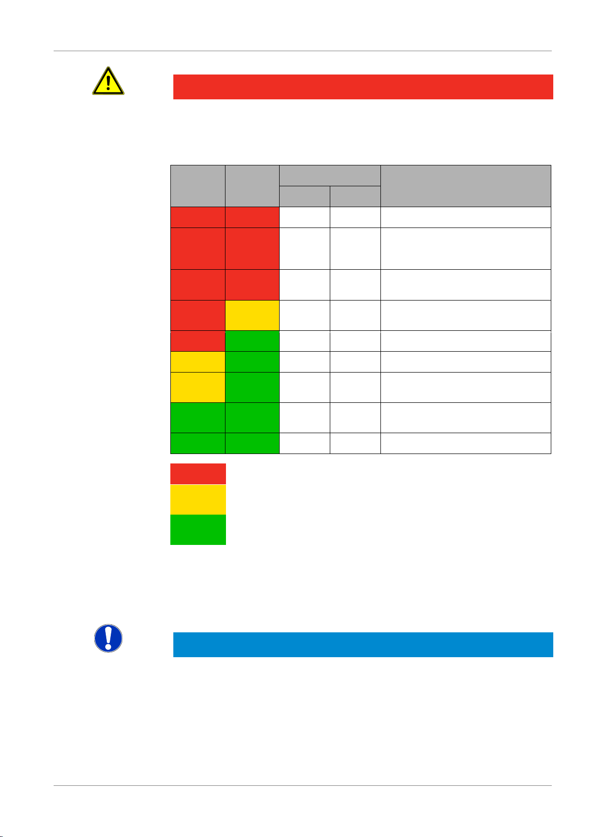
DANGER
Danger due to elevated CO2 concentration
The product is not suitable for use as personal protective equipment with elevated
CO2 levels. However, it can indicate an elevated CO2 value. The measured value appears in the display as a % or ppm value.
G 1910-02
G 1910-20
CO2 concentration
Effect
%
ppm
20 Death within a few seconds
10 Loss of consciousness, death, dizziness, vomiting, headaches, reduced
blood flow to brain
4.0 IDLH - immediate danger to life and
health
3.0 Normal exhalation concentration, elevated breathing and pulse rate
2,0
20,000
1.0
10,000
Possible shortness of breath
0.5
5000
TWA – Maximum for working conditions
0.1 .. 0.2
1000 ..
2000
Recommended maximum value in
public areas
0.04
400
Fresh air
Product is not permitted for the area
Expanded measuring range. The product can be
used conditionally
Area of application of the product with specified
accuracy
The values are guideline values. Depending on the health condition and duration of
exposure, problems can also occur below the indicated concentrations under certain
circumstances.
2.3 Safety instructions
NOTE
This product does not belong in children's hands!
Page 8

2 | Safety
G 1910-02
8 / 30
B-H90.0.01.DB2-2.1
2.4 Intended use
The product is designed exclusively for measurements in ambient air and environments with slightly elevated CO2 concentrations in areas that are not harmful to the
health. It is designed to be carried on the body for mobile use. The user can be
warned optically and acoustically of elevated CO2 concentrations based on variable
alarm limits. Example applications for this are:
– Use as a monitor for recording of the mean value weighted over 8 hours (TWA) or
15 minutes (STEL).
– Monitoring of air quality.
2.5 Qualified personnel
For commissioning, operation and maintenance, the relevant personnel must have
adequate knowledge of the measuring process and the significance of the measurements. This document makes a valuable contribution to this. The instructions in this
document must be understood, observed and followed.
In order to avoid any risks arising from interpretation of the measurements in the concrete application, the user must have additional expertise. The user is solely liable for
damages/danger resulting from misinterpretation due to inadequate expertise.
Page 9

G 1910-02
Description | 3
B-H90.0.01.DB2-2.1
9 / 30
3 Description
3.1 Scope of delivery
Please check to ensure the completeness of the product after opening the package.
You should find the following components:
– Quick reference guide
– Handheld measuring device, ready for operation, including rechargeable batteries
– Micro USB to USB type A connection cable
3.2 Functional description
The product offers precision, speed and reliability in a compact, ergonomic housing. It
is distinguished by an illuminated 3-line display. The product can be switched on,
switched off and configured and the measurements and parameters can be adjusted
and held with the operating elements. The product is equipped with an integrated optical carbon dioxide sensor. In addition to display of the currently measured CO2 value,
the mean value weighted over 8 hours (TWA) or 15 minutes (STEL) can be output.
An integrated two-stage alarm also issues an optical signal and an acoustic signal as
a warning when the adjusted limits are exceeded.
– A pre-alarm issues a text warning or the backlight flashes with a brief horn when
the limit is exceeded depending on the setting.
– A pre-alarm issues a text warning or the backlight flashes rapidly with a continu-
ous horn when the limit is exceeded depending on the setting.
Page 10

10 / 30
B-H90.0.01.DB2-2.1
4 | The product at a glance
G 1910-02
4 The product at a glance
4.1 The G 1910-02
LCD Display
Front view
Sensor openings
Micro USB socket
4.2 Display elements
Display
Charge status display
Evaluation of the charge status
Unit display
Display of units or type of mode, min/max/hold
Main display
Measurement of the current CO2 value
Auxiliary display
Display of the mean value
Bar graph
Visualisation of the CO2 value
4.3 Operating elements
On / Off button
Press briefly
Switch on the product
Activate / deactivate lighting
Long press
Switch off the product
Reject changes in a menu
Up / Down button
Press briefly
Display of the min/max value
Change value of the selected parameter
Long press
Reset the min/max value of the current measurement
Both simultaneously
Rotate display, overhead display
Page 11

G 1910-02
The product at a glance | 4
B-H90.0.01.DB2-2.1
11 / 30
Function key
Press briefly
Freeze measurement (Hold)
Return to measurement display
Call up next parameter
Long press, 2s
Start menu configuration, (ONF appears in the display
4.4 Connections
Micro USB socket
Charging the batteries
Page 12

12 / 30
B-H90.0.01.DB2-2.1
5 | Operation
G 1910-02
5 Operation
5.1 Commissioning
5.1.1 Explanation
The product is switched on with the On/Off button. It may be necessary to configure
the product after switching on. See Configuration [ 12].
A self-test is conducted after switching on. The following increasing CO2 values 1000,
2000, 4000 and 8000 are shown in the display. TEST is shown in the secondary display.
If an alarm is active and is in one of these relevant areas, it is triggered.
If ---- appears in the display after the self-test, the sensor is not ready for measure-
ment.
If batteries are drained and the product is not used for an extended time, it can take up
to 30 seconds until the measurement starts. If no measurement is received by the
sensor within 30 seconds, the product issues an alarm.
– The rechargeable batteries have been charged via the micro USB socket.
– Press the On/Off button.
Information about the configuration of the product appears in the display.
TEST
Self-test
An automatic self-test is carried out during system
start-up. The bar indicator for the threshold value is
displayed and the alarm is tested if it has been activated.
POFF
Automatic shutoff
Automatic shut-off activated. The product is
switched off if no buttons have been pressed after
the adjusted time
– The product is now ready for measurement.
5.2 Configuration
5.2.1 Explanation
The following steps describe how to adapt the product for your purposes.
NOTE
There are various configuration parameters available depending on the product version and configuration. These can vary depending on the product version and configuration.
5.2.2 Opening the configuration menu
In order to configure the product, you must first open the Configuration menu. The
menu is opened as shown in the illustration.
1. Press the Function key for 2 seconds to open the Configuration menu.
2. (ONF appears in the display. Release the function key.
Description
Prerequisite
Instruction
Outcome of an action
Description
Prerequisite
Instruction
Page 13

G 1910-02
Operation | 5
B-H90.0.01.DB2-2.1
13 / 30
3. By briefly pressing the Function key, you can scroll through the parameters. Select
the parameter you would like to configure.
4. When you have selected the desired parameter, change the parameter to the de-
sired value with the Up button and the Down button.
5. The changes are saved after running through the entire Configuration menu. STOR
appears in the display. The Configuration menu can be exited from any arbitrary
parameter by pressing and holding the Function key for 2 seconds. The changes
made up that point are saved.
Call up menu
Next parameter
Change value
Save changes
Discard
changes
2s Press: Single
step
Hold: Fast
change
2s
2s
Product is
switched off
The Configuration menu is closed after the last parameter.
NOTE
If the product is switched off without saving the configuration, the last save value is
reproduced on the next start-up of the product.
5.2.3 Configuring parameters of the configuration
menu
The following representation shows the available parameters and various configuration options.
– The Configuration menu is open. See Opening the configuration menu [ 12].
1. Select the desired parameter you would like to configure.
2. Adjust the desired configuration in the selected parameter with the Up button and
Down button.
3. The available configuration options are listed for each parameter in the following
representation.
The changed value is saved and the Configuration menu is closed. STOR appears in
the display. If necessary, the product is restarted automatically in order to adopt the
changed values.
NOTE
The configuration is closed if no button is pressed for 2 minutes. Any changes made
up to that point are not saved. C.END appears in the display.
Parameter
Values
Meaning
Representation
Outcome of an action
Description
Prerequisite
Instruction
Outcome of an action
Representation
Page 14

14 / 30
B-H90.0.01.DB2-2.1
5 | Operation
G 1910-02
Input
INP
%
CO2 measurement in %
PPm
CO2 measurement in ppm
Alarms
AL.
OFF
No active alarm
ON
Alarm alerting via text display, acoustic signal and
flashing of the backlighting
BEEP
Alarm alerting via text display and acoustic signal
L,TE
Alarm alerting via text display and flashing of the
backlighting
AL.1 Depending on the setting of the parameter value INP
0.000 .. AL.2
0 .. AL2
Min. alarm limit in % or ppm; a pre-alarm is triggered when the value is exceeded
When the pre-alarm is triggered, it can be muted for
5 minutes. To do this, press any key. The display
shows (LR AL.1.
AL.2 Depending on the setting of the parameter value INP
AL.1 .. 1.000
AL1 .. 10000
Max. alarm limit in % or ppm; the main alarm is triggered when the value is exceeded
Mean value
LCD.2
8 H
Time weighted over 8 hours, mean value TWA
STEL
Time weighted over 15 minutes, mean value STEL
OFF
Mean value determination deactivated
Shut-off time
POFF
OFF
No automatic shut-off
0:15 0:30 1:00 4:00
12:00
Automatic shut-off after a selected time in hours
and minutes, during which no buttons have been
pressed
Page 15

G 1910-02
Operation | 5
B-H90.0.01.DB2-2.1
15 / 30
Backlight
L,TE
OFF
Backlight deactivated
0:15 0:30 1:00 4:00
Automatic shut-off of the backlight after a selected
time in minutes and seconds, during which no buttons have been pressed
ON
No automatic shut off of the backlight
Factory settings
IN,T
NO
Use current configuration
YES
Reset product to factory settings. IN,T DONE appears
in the display
5.2.4 Call-up of the expanded settings menu
In order to configure the product, you must first open the Expanded settings menu.
The menu is opened as shown in the illustration.
– The product is switched off.
1. Press and hold the Down button.
2. Press the On/Off button to switch on the product.
3. Release the On/Off button after 1 second and then the Down button in order to call
up the Expanded settings menu. The display shows the first parameter.
4. By briefly pressing the Function key, you can scroll through the parameters. Select
the parameter you would like to configure.
5. When you have selected the desired parameter, change the parameter to the de-
sired value with the Up key and the Down key.
6. In order to save the new parameter value, press and hold the Function key for
longer than 2 seconds.
Call up menu
Hold
1s
Release
Release
The Expanded settings menu is closed after the last parameter.
Description
Prerequisite
Instruction
Representation
Outcome of an action
Page 16

16 / 30
B-H90.0.01.DB2-2.1
5 | Operation
G 1910-02
NOTE
If the Expanded settings menu is processed completely, the changes are saved automatically. STOR appears in the display. However, it can be exited at any time by press-
ing the Function key for 2 seconds. The changes made up that point are also saved.
If the product is switched off without saving the configuration, the last save value is
reproduced on the next start-up of the product.
5.2.5 Configure parameters of the expanded settings
menu
The following representation shows the available parameters and various configuration options.
– The Expanded settings menu is called up. See Call-up of the expanded settings
menu [ 15].
1. Select the desired parameter you would like to configure.
2. Adjust the desired configuration in the selected parameter with the Up key and
Down key.
3. The available configuration options are listed for each parameter in the following
representation.
Parameter
Values
Meaning
Adjustment
[AL
OFF
No adjustment
2.PT
2-point adjustment
1.PT
1-point adjustment
KARD
Basic sensor adjustment
Only 0 ppm or 0.000 % can be selected as a set-
point value for the adjustment, such as, for example
on nitrogen or 400 ppm or 0.040 % for adjustment
on clean ambient air.
Gradient adjustment specification
[.SL
350 .. 10,000
0.035 .. 1.000
Setpoint value in ppm or in % for 1.PT or 2.PT adjustment
0 / 400
0.000 / 0.040
Setpoint value in % or in ppm for KARD adjustment
Description
Prerequisite
Instruction
Representation
Page 17

G 1910-02
Operation | 5
B-H90.0.01.DB2-2.1
17 / 30
NOTE
The setpoint value of 400 ppm or depending on selection 0.040 % can be used for a
simple adjustment in clean ambient air. Otherwise, use the expected value of the test
gas according to the analysis certificate or display value of the reference device.
The changed value is saved and the Expanded settings menu is closed. STOR appears
in the display.
NOTE
If the product is switched off without saving the configuration, the last save value is
reproduced on the next start-up of the product.
Outcome of an action
Page 18

6 | Measurement Basics
G 1910-02
18 / 30
B-H90.0.01.DB2-2.1
6 Measurement Basics
6.1 NDIR CO2 sensor
6.1.1 Explanation
The sensors are based on non-dispersive infrared sensor technology, NDIR. This is
the most widely used sensor technology for CO2 measurement.
The principle of the NDIR sensor is that an IR light source is focusses so that an optical beam is created, which passes through the existing gas, including CO2. After an
optical band pass filter is passed, an IR sensor measures the level of IR light, wherein
the CO2 values in the optical path are displayed.
6.1.2 Design
1. Gas inlet
2. Gas outlet
3. IR lamp
4. Optical filter
5. Thermopile detector
IR detectors
A sensor module with single-channel detectors is used for the product.
A micro light bulb is used as an IR radiation source. It emits a broadband spectrum.
The sensor is long-lasting and maintenance-free. In order to be able to maintain the
specified accuracy for many years to come, regular adjustment must be carried out
depending on the required accuracy.
IR radiation source
Page 19

B-H90.0.01.DB2-2.1
G 1910-02
19 / 30
Operation and maintenance | 7
7 Operation and maintenance
7.1 Operating and maintenance notices
CAUTION
Damage to the sensor
A sensitive optical sensor is installed in the product. The sensor parameters can
change due to impact or falling. This can result in incorrect measurements.
– Protect the product from impact and falling!
– The measurements must be checked after the product falls or is jarred. If the val-
ues deviate, a basic sensor adjustment must be carried out!
NOTE
The product must be handled with care and used in accordance with the technical
data. Do not throw or strike.
NOTE
If the product is stored at a temperature above 50 °C, or is not used for an extended
period of time, the batteries must be removed or recharged regularly. This prevents
leaks from the rechargeable batteries and increases the life of the rechargeable batteries.
7.2 Battery
7.2.1 Charge status display
If the battery status display blinks, the batteries are depleted and must be recharged.
However, the device will still operate for a certain length of time.
If the BAT display text appears in the main display, the rechargeable battery voltage is
no longer adequate for operation of the product. Now the rechargeable battery is fully
depleted.
7.2.2 Charging the batteries
– Charge via Micro USB socket with the accompanying cable.
– Must be operated on a USB port or USB mains adapter with an output voltage of
4.75 V .. 5.25 V, which can deliver a current of 500 mA.
– The charging process is visualised in the charge status display.
– If the charging process has concluded BAT FVLL is shown in the display.
– Charging at room temperature in a range of 0 .. 40 °C is permitted.
– The device can heat up during charging. Max. up to 50 °C.
– Charging time approx. 8 hours.
– The charging time can take longer in ambient temperatures above 30 °C.
– The rechargeable battery temperature is monitored. At temperatures below 0 °C
and above 50 °C, the charging is interrupted.
Page 20

20 / 30
B-H90.0.01.DB2-2.1
7 | Operation and maintenance
G 1910-02
– In order to protect the batteries, the charging process is not started when the
charge cable is plugged in, if fully charged batteries are detected based on the
voltage monitor.
7.2.3 Rechargeable battery replacement
DANGER
Danger of explosion!
Using damaged or unsuitable rechargeable batteries can generate heat, which can
cause the rechargeable batteries to crack and possibly explode!
– Only use high-quality and suitable NiMH rechargeable batteries!
CAUTION
Damage!
If the rechargeable batteries have different charge levels, leaks and thus damage to
the product can occur.
– Use new, high-quality rechargeable batteries!
– Do not use different types of rechargeable batteries!
– Remove depleted rechargeable batteries and dispose of them at a suitable collec-
tion point!
NOTE
Read the following handling instructions before replacing rechargeable batteries and
follow them step by step. If disregarded, the product could be damaged or the protection from moisture could be diminished.
Proceed as follows to replace the rechargeable batteries.
– The product is switched off.
Fig. 1: Batteriewechsel
1. Unscrews the Phillips screws (A)and
remove the cover.
2. Carefully replace the two Mignon AA
batteries (B). Ensure that the polarity
is correct! It must be possible to insert
the batteries in the correct position
without using force.
3. The O-ring (C) must be undamaged,
clean and positioned at the intended
depth. In order to facilitate assembly
and avoid damage, a suitable grease
can be applied.
4. Fit the cover on evenly. The O-ring
must remain at the intended depth!
5. Tighten the Phillips screws (A).
The product is now ready for use again.
Description
Prerequisites
Instruction
Outcome of an action
Page 21

B-H90.0.01.DB2-2.1
G 1910-02
21 / 30
Operation and maintenance | 7
7.3 CO2 adjustment
In order to improve the accuracy, the carbon dioxide sensor can be adjusted. In order
to conduct a CO2 adjustment, proceed as follows.
1-point adjustment
Used for optimisation of the accuracy at the adjustment point. The best possible accu-
racy can be achieved even with elevated CO2 concentrations
2-point adjustment
Used for optimisation of the accuracy for extreme requirements over a wide measuring
range beginning from 0 ppm.
Basic sensor adjustment
Used to reset the sensor in case of deviations beyond the normally expected devia-
tions. The values of all prior adjustments are reset and cannot be restored. A plausibility check of the carbon dioxide concentrations does not take place. Depending on the
setting, adjustment to 0 ppm CO2 test gas or fresh outside air can take place. Ensure
that the setting of the gradient compensation setpoint [.SL was entered correctly in the
Expanded settings menu.
If reliable values can no longer be displayed, we recommend performing basic sensor
adjustment of the zero point at 0 ppm CO2 with nitrogen and a possibly necessary additional gradient compensation via 1-point adjustment.
If incorrect values are displayed after the adjustment, e.g. ERR.2 at 0 ppm CO2, the
adjsutment must be repeated.
NOTE
Adjustment can be carried out in clean ambient air or with test gases (optionally available gas extraction device recommended). 1-point adjustment at any arbitrary point
above 350 ppm and 2-point adjustment at 0 ppm and an arbitrary point above 350
ppm are both possible.
For automatic adjustment, open the Adjustment menu.
– The product is switched on.
– Clean ambient air or test gas for gradient correction
– Test gas 0 ppm CO2 for zero point adjustment for 2-point adjustment or basic sen-
sor adjustment at 0 ppm
– Gas extraction device, if applicable
Description
Prerequisite
Page 22

22 / 30
B-H90.0.01.DB2-2.1
7 | Operation and maintenance
G 1910-02
1. If you would like to perform a adjustment with test gas, connect the extraction de-
vice to the product first.
2. Press the Function key for 4 seconds to start the adjustment. [ONF appears in the
display first, then [AL.
3. 1-point, 2-point or basic sensor adjustment is started. This depends on what was
adjusted in the Expanded settings menu.
1-point adjustment
1. [.SL appears in the display for 1-point adjustment.
2. The product determines a stable value first. If the measured value is outside of the
value range integrated in the product, the display flashes briefly and an acoustic
signal is issued every 10 s.
3. If a stable correct value is reached, the display flashes briefly, an acoustic signal
sounds and the bar indicator blinks.
4. You can change the value of the gradient compensation with the up key and down
key. Otherwise, confirm the preadjusted value with the function key. The 1-point
adjustment is finished.
2-point adjustment
1. [.OF appears in the display for 2-point adjustment.
2. Allow the test gas to flow at about 0.5 l/min at 0 ppm of CO2. The product deter-
mines a stable value first. If the measured value is outside of the value range integrated in the product, the display flashes briefly and an acoustic signal is issued
every 10 s.
3. If a stable correct value is reached, the display flashes briefly, an acoustic signal
sounds and the bar indicator blinks. [.SL appears in the display.
4. Remove the test gas and connect a second test gas to the extraction device. The
product determines a stable value first. If the measured value is outside of the
value range integrated in the product, the display flashes briefly and an acoustic
signal is issued every 10 s.
Instruction
Page 23

B-H90.0.01.DB2-2.1
G 1910-02
23 / 30
Operation and maintenance | 7
5. If the display flashes briefly, an acoustic signal sounds and the bar display blinks,
a stable correct value has been achieved.
6. You can change the value of the gradient compensation with the up key and down
key. Otherwise, confirm the preadjusted value with the function key. Remove the
extraction device. The 2-point adjustment is finished
Basic sensor adjustment
1. KARD appears in the display for basic sensor adjustment.
2. Depending on the specification [.SL, let the test gas with 0 ppm CO2 flow in at ap-
prox. 0.5 l/Min or move the product into clean ambient are with 400 ppm CO2. The
product determines a stable value first. If the displayed measurement is outside of
the measuring range of the sensor, the product cannot perform stability recognition. It must be ensured that the carbon dioxide concentration at the sensor is stable before the adjustment is started.
3. If a stable correct value is reached, the display flashes briefly, an acoustic signal
sounds and the bar indicator blinks.
4. Remove the extraction device, if applicable.
NOTE
Current test gases normally have accuracies of ± 2 %. This tolerance must be taken
into consideration with the measurement uncertainty. The specifications on the analysis certificate must always be observed.
NOTE
For information about the available adjustment settings, refer to Configuring parameters of the configuration menu [ 13].
After the adjustment is finished [AL DONE is displayed.
Then, the current measurement is shown in the display again.
If the adjustment is not completed successfully an error message is displayed. [AL ERR.
appears in the display. See Error and system messages [ 24]. Confirm the error message pressing the Function key. The product restarts. The values of the last correctly
performed adjustment are restored.
Configure parameters of the expanded settings menu [ 16]
Outcome of an action
Page 24

24 / 30
B-H90.0.01.DB2-2.1
8 | Error and system messages
G 1910-02
8 Error and system messages
Display
Meaning
Possible causes
Remedy
----
No signal from the
sensor
Measurement far
outside of the measuring range
Sensor not ready
CO2 concentration
too high
Defective sensor ad-
justment
Sensor defect
Wait the start-up time of the
sensor
Place the product in clean
outdoor air
Perform sensor adjustment
Send in for repair
----
The display value
could not be determined
Sensor not ready
Sensor defect
Wait the start-up time of the
sensor
Send in for repair
No display,
unclear characters or no
response
when buttons are
pressed
Rechargeable battery depleted
System error
Product is defective
Rechargeable battery depleted
Error in the product
Product is defective
Charge battery
Replace rechargeable bat-
tery
Send in for repair
BAT LO
Rechargeable battery depleted
Rechargeable battery discharged
Rechargeable battery defect
Charge battery
Replace rechargeable bat-
tery
(AL ERR.1
Zero point adjustment defective
Incorrectly measured CO2 concentration for adjustment
Expose sensor to a test gas
with 0 ppm CO2
(AL ERR.2
(AL ERR.3
Defective gradient
compensation
Incorrectly measured CO2 concentration for adjustment
Incorrect CO2 concentration
Expose sensor to a test gas
with known CO2 concentration
Enter correct value
(AL ERR.5
Time for stability
recognition exceeded
Stability recognition
lasts longer than 10
minutes
Provide a consistent flow
with a constant CO2 concentration
ERR.1
Measuring range exceeded
Measurement too
high
Defective sensor adjustment
Sensor defect
Stay within allowable measurement range
Perform sensor adjustment
Send in for repair
ERR.2
Measuring range is
undercut
Defective sensor adjustment
Sensor defect
Perform sensor adjustment
Send in for repair
ERR.7
Sensor error
Defective sensor adjustment
Sensor defect
Perform sensor adjustment
Send in for repair
Page 25

B-H90.0.01.DB2-2.1
25 / 30
G 1910-02
Error and system messages | 8
ERR.T
Temperature error
Permissible temperature range during
charging exceeded
or undercut
Charging of battery only at 0
.. 40 °C
Bring product to room temperature and restart charging process
SYS ERR
System error
Error in the product
Sensor defect
Switch product on/off
Replace rechargeable bat-
teries
Send in for repair
STAB
No measurement
change within 2
minutes
Product in extremely
constant environment
Sensor defect
Place the product in clean
outdoor air
Perform sensor adjustment
Send in for repair
Page 26

9 | Disposal
G 1910-02
26 / 30
B-H90.0.01.DB2-2.1
9 Disposal
Separation by material and recycling of device components and packaging must take
place at the time of disposal. The valid regional statutory regulations and directives
applicable at the time must be observed.
NOTE
The device must not be disposed of with household waste. Return it to us, freight prepaid. We will then arrange for the proper and environmentally-friendly disposal.
Private end users in Germany have the possibility of dropping off the product at the
municipal collection centre.
Please dispose of empty batteries at the collection points intended for this purpose.
NOTE
Fill in the return form available from the information base online at www.ghm-group.de
and sent it in with the product.
Page 27

G 1910-02
Technical data | 10
B-H90.0.01.DB2-2.1
27 / 30
10 Technical data
Measuring range (specified accuracy)
0 .. 2000 ppm
0.000 .. 0.200 %
Measuring range (not specified)
0.000 .. 1.000 %
Accuracy
± 70 ppm ± 3 % measurement
Measuring cycle
2 seconds
Display
3-line segment LCD, additional symbols, illuminated (adjustable white, permanent illumination)
Additional functions
Min/Max/Hold
TWA calculation / STEL
2-stage alarm (optical and acoustic)
Adjustment
1-point, 2-point and basic sensor adjustment
Housing
Break-proof ABS housing
Protection rating
IP30
Dimensions L*W*H
[mm] and weight
108 * 54 * 28 mm without measuring cell or kink protection
180 g, incl. battery and measuring cell
Operating conditions
0 to 50 °C; 0 to 85 % r.h. (non-condensing)
Storage temperature
-20 to 70 °C
Current supply
2*AA-NiMH batteries (included in delivery)
Current requirement/
Rechargeable battery
life
approx. 50 mA, approx. 60 mA with lighting
Life approx. 24 hours with NiMH batteries (without backlight)
charging time of about 8 hours
Battery indicator
4-stage charge status indicator,
Charge indicator for low charge level: "BAT LO"
Plug connector
Micro USB socket (not a data connection)
Auto-power-OFF function
The device switches off automatically if this is activated
Directives and standards
The devices conform to the following Directives of the Council
for the harmonisation of legal regulations of the Member
States:
2014/30/EU EMC Directive
2011/65/EU RoHS
Applied harmonised standards:
EN 61326-1:2013 Emission limits: Class B
Immunity according to Table 2
Additional errors: < 1 % FS
EN 50581:2012
The device is intended for mobile use and/or stationary operation in the scope of the specified operating conditions without
further limitations.
Page 28

11 | Spare parts and accessories
G 1910-02
28 / 30
B-H90.0.01.DB2-2.1
11 Spare parts and accessories
A selection of spare parts and accessories for this product is listed below.
Number
Name
Description
410355
NiMH rechargeable battery
NiMH replacement rechargeable battery
411907
GKK 1002
G1000 series case, 235 x 185 x 48 mm
476698
GZ-18
Gas cylinder with 12 l test gas: 5000 ppm CO2
476699
GZ-19
Adjustment set for G 1910: MiniFlo valve for 12 l gas
cylinders, quick-connect adapter 4 mm, closing screw,
gas-bezel
479767
GZ-20
Gas connection for G 1910: Quick-connect adapter 6
mm, spare closing screw, gas bezel
481885
G 1000 table
base and wall
suspension
Plastic holder with connection possibility for USB cable
A complete list of all accessories- and spare parts is available in our product catalogue
or on our home page. We can also provide further information by phone.
Internet:www.greisinger.de
Tel: +49 94029383-52
Article
Contact
Page 29

B-H90.0.01.DB2-2.1
29 / 30
G 1910-02
Service | 12
12 Service
12.1 Manufacturer
If you have any questions, please do not hesitate to contact us:
GHM Messtechnik GmbH
GHM GROUP - Greisinger
Hans-Sachs-Str. 26
93128 Regenstauf | GERMANY
Email: info@greisinger.de | www.greisinger.de
WEEE reg. no. DE 93889386
12.2 Repairs processing
Defective products are repaired professionally and quickly in our service centre.
Monday to Thursday from 8:00 to 16:00
Friday from 8:00 to 13:00
GHM Messtechnik GmbH
GHM GROUP - Greisinger
Hans-Sachs-Str.26
Service Centre
93128 Regenstauf | GERMANY
Tel: +49 94029383-39
Fax: +49 94029383-33
service@greisinger.de
NOTE
Fill in the return form available from the information base online at www.ghm-group.de
and sent it in with the product.
12.3 Sales offices
Post code:
00000 – 25999 | 27000 – 34999
37000 – 39999 | 98000 – 99999
Email:
vertrieb-nord@ghm-messtechnik.de
Tel:
+49 4067073-0
Fax:
+49 4067073-288
Contact
Open hours and contact
North Sales Office
Page 30

30 / 30
B-H90.0.01.DB2-2.1
12 | Service
G 1910-02
Post code:
26000 – 26999 | 35000 – 36999
40000 – 69999
Email:
vertrieb-west@ghm-messtechnik.de
Tel:
+49 2191 9672-0
Fax:
+49 2191 9672-40
Post code:
70000 – 97999
Email:
vertrieb-sued@ghm-messtechnik.de
Tel:
+49 9402 9383-52
Fax:
+49 9402 9383-33
West Sales Office
South Sales Office
 Loading...