

Page 1
Operating manual
EN
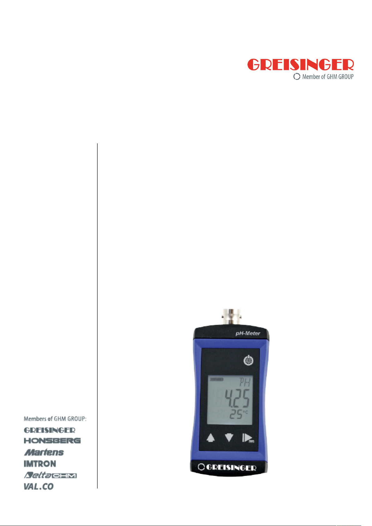
G 1500
pH measuring device
Page 2

Table of contents
Table of contents
1 About this documentation ................................................................................................................. 4
1.1 Foreword............................................................................................................................................... 4
1.2 Purpose of the document...................................................................................................................... 4
1.3 Legal notices......................................................................................................................................... 4
1.4 Correctness of content.......................................................................................................................... 4
1.5 Layout of this document........................................................................................................................ 4
1.6 Further information ............................................................................................................................... 5
2 Safety ................................................................................................................................................... 6
2.1 Explanation of safety symbols .............................................................................................................. 6
2.2 Foreseeable misuse ............................................................................................................................. 6
2.3 Safety instructions ................................................................................................................................ 7
2.4 Intended use ......................................................................................................................................... 8
2.5 Qualified personnel............................................................................................................................... 8
3 Description .......................................................................................................................................... 9
3.1 Scope of delivery .................................................................................................................................. 9
3.2 Functional description........................................................................................................................... 9
4 The product at a glance ................................................................................................................... 10
4.1 The G 1500......................................................................................................................................... 10
4.2 Display elements ................................................................................................................................ 10
4.3 Operating elements ............................................................................................................................ 10
4.4 Connections........................................................................................................................................ 11
5 Bases for measurement ................................................................................................................... 12
5.1 pH measurement ................................................................................................................................ 12
5.1.1 Explanation ......................................................................................................................................... 12
5.1.2 pH electrode ....................................................................................................................................... 12
5.1.3 Design................................................................................................................................................. 13
5.1.4 Further information ............................................................................................................................. 13
5.1.5 Choosing a pH electrode .................................................................................................................... 13
5.1.6 Service life .......................................................................................................................................... 14
5.1.7 Care and maintenance ....................................................................................................................... 14
6 Operation and maintenance ............................................................................................................ 16
6.1 Operating and maintenance notices ................................................................................................... 16
6.2 Battery ................................................................................................................................................ 16
6.2.1 Battery indicator.................................................................................................................................. 16
6.2.2 Changing battery ................................................................................................................................ 16
6.3 Calibration and adjustment ................................................................................................................. 17
6.3.1 pH calibration...................................................................................................................................... 17
6.4 Calibration and adjustment service..................................................................................................... 22
6.4.1 Certificates.......................................................................................................................................... 22
7 Operation........................................................................................................................................... 23
7.1 Commissioning ................................................................................................................................... 23
7.1.1 Explanation ......................................................................................................................................... 23
7.2 Configuration ...................................................................................................................................... 23
7.2.1 Explanation ......................................................................................................................................... 23
7.2.2 Opening the configuration menu......................................................................................................... 23
2 / 34 B-H86.0.11.DB2-1.0
Page 3

Table of contents
7.2.3 Configuring parameters of the configuration menu............................................................................. 24
7.2.4 Adjustment of the measuring input ..................................................................................................... 25
8 Error and system messages............................................................................................................ 27
9 Disposal............................................................................................................................................. 29
10 Technical data................................................................................................................................... 30
11 Spare parts and accessories ........................................................................................................... 31
12 Service ............................................................................................................................................... 32
12.1 Manufacturer....................................................................................................................................... 32
12.2 Repairs processing ............................................................................................................................. 32
12.3 Sales offices ....................................................................................................................................... 32
12.4 Sales subsidiaries............................................................................................................................... 33
B-H86.0.11.DB2-1.0 3 / 34
Page 4

1 | About this documentation G 1500
1 About this documentation
1.1 Foreword
Read this document carefully and familiarise yourself with the operation of the product
before you use it. Keep this document ready to hand and in the immediate vicinity of
the product so that it is available to the personnel/user for reference at all times in
case of doubt.
The product was developed according to the state of the art and fulfils the requirements of the applicable European and national Directives. All corresponding documents are available from the manufacturer.
Only technically qualified persons are permitted to carry out commissioning, operation,
maintenance and decommissioning. The qualified personnel must have carefully read
and understood the operating manual before beginning any work.
1.2 Purpose of the document
– It provides important information for working safely and efficiently with the product.
– In addition to the quick reference guide with all relevant legal and safety content in
hard copy, this document is a detailed reference option for the product.
1.3 Legal notices
The liability and warranty of the manufacturer for damages and consequential damages are voided with misuse, disregarding this document, disregarding safety notices,
assignment of inadequately qualified technical personnel and arbitrary modifications of
the product.
Only carry out the maintenance and service tasks on this product that are described in
this documentation. In the process, adhere to the specified steps. For your own safety,
only use original spare parts and accessories of the manufacturer. We assume no liability for the use of other products and resulting damage.
This document is entrusted to the recipient for personal use only. Any impermissible
transfer, duplication, translation into other languages or excerpts from this operating
manual are prohibited.
The manufacturer assumes no liability for print errors.
1.4 Correctness of content
The contents of this document were checked for corrected and are subject to a continuous correction and updating process. This does not rule out potential errors. In the
event that errors are discovered or in case of suggestions for improvement, please inform us immediately via the indicated contact information in order to help us make this
document even more user-friendly.
1.5 Layout of this document
Description
Each chapter is explained at the beginning in the description.
Prerequisite
All mandatory prerequisites are then listed for each step.
4 / 34 B-H86.0.11.DB2-1.0
Page 5

G 1500 About this documentation | 1
Instruction
Tasks to be carried out by the personnel / user are represented as numbered instructions. Adhere to the sequence of the specified instructions.
Representation
Shows an illustrative instruction or a configuration of the product.
Formula
Some instructions include a formula for a general understanding of a configuration,
programming or a setting of the product.
Outcome of an action
Result, consequence or effect of an instruction.
Emphases
In order to simplify legibility and provide a clearer overview, various sections / information are emphasised.
– 1234 Display elements
– Mechanical controls
– Product functions
– Product labels
– Cross-reference [}p.4]
– Foot notes
1.6 Further information
Software version of the product:
– V1.2 or later
B-H86.0.11.DB2-1.0 5 / 34
Page 6
2 | Safety G 1500
2 Safety
2.1 Explanation of safety symbols
DANGER
This symbol warns of imminent danger which can result in death, severe bodily injury,
or severe property damage in case of non-observance.
DANGER
This symbol indicates danger for living tissue as well as a variety of materials, which
can be damaged or destroyed when coming into contact with this chemical. Caustic
effect, protective equipment required!
DANGER
This symbol indicates danger for all life forms, which can result in death or acute or
chromic damage to the health after inhaling, swallowing or absorbing this chemical
through the skin.
CAUTION
This symbol warns of potential dangers or harmful situations which can cause damage
to the device or to the environment in case of non-observance.
NOTE
This symbol indicates processes which can have a direct influence on operation or
can trigger an unforeseen reaction in case of non-observance.
NOTE
This symbol instructs the use of eye protection which protects the eyes from harmful
influences when working with powerful light, UV radiation, laser, chemicals, dust,
splinters or weather influences.
NOTE
This symbol instructs the use of protective gloves which offer protection from mechanical, thermal, chemical, biological or electrical hazards.
2.2 Foreseeable misuse
The fault-free function and operational safety of the product can only be guaranteed if
generally applicable safety precautions and the device-specific safety instructions for
this document are observed.
If these notices are disregarded, personal injury or death, as well as property damage
can occur.
6 / 34 B-H86.0.11.DB2-1.0
Page 7
G 1500 Safety | 2
DANGER
Incorrect area of application!
In order to prevent erratic behaviour of the product, personal injury and property damage, the product must be used exclusively as described in the chapter Description
[}p.9] in the operating manual.
– The product is not suitable for use in explosion-prone areas!
– The product must not be used for diagnostic or other medical purposes on pa-
tients!
– The product is not intended to come into direct contact with food. For measure-
ment in foods, samples must be taken and discarded after the measurement!
– Not suitable for use with requirements on functional safety, e.g. SIL!
2.3 Safety instructions
This product has been designed and tested according to the safety requirements for
electronic measuring devices. The product must be used according to the technical
data. Technical data [}p.30].
DANGER
Danger of breaking the electrodes!
All electrodes contain glass parts that can cause injuries when broken. There is an elevated risk of injury in connection with measurements in foods.
– Inspect the electrode before and after the measurement!
– Always measures in samples for measurements in foods. Discard these samples
after the measurement!
DANGER
Potassium chloride!
The pH and Redox electrodes contain potassium chloride or potassium, nitrate. All
contact with the skin, clothing and eyes should be avoided. Nevertheless, should contact occur, take the following measures.
– As a fundamental rule, protective equipment (e.g. gloves) must be worn as inten-
ded for the purpose of use!
– Do not eat, drink or smoke in areas where chemicals are used!
– In case of problems, consult with trained, qualified personnel immediately!
– Eyes: Flush with flowing water for at least 15 minutes, seek medical attention!
– Skin: Wash with large amounts of water for several minutes!
– Clothing: Wash immediately!
– If swallowed: Drink large amounts of water, do not induce vomiting and seek med-
ical attention!
B-H86.0.11.DB2-1.0 7 / 34
Page 8
2 | Safety G 1500
CAUTION
Erratic behaviour!
On suspicion that the product can no longer be operated without danger, it must be
decommissioned and prevented from recommissioning with appropriate labelling. The
safety of the user can be impaired by the device if, for example, if it shows visible
damage, it no longer works as specified or if it was stored for an extended period of
time under unsuitable conditions.
– Visual inspection!
– In case of doubt, send the product to the manufacturer for repair or maintenance!
NOTE
This product does not belong in children's hands!
2.4 Intended use
The product is designed for measuring the pH value in water and aqueous media by
means of suitable electrodes.
Application examples for this are, for example, drinking water, waste water, surface
water, swimming pools, fish breeding and process chemistry.
2.5 Qualified personnel
For commissioning, operation and maintenance, the relevant personnel must have adequate knowledge of the measuring process and the significance of the measurements. This document makes a valuable contribution to this. The instructions in this
document must be understood, observed and followed.
In order to avoid any risks arising from interpretation of the measurements in the concrete application, the user must have additional expertise. The user is solely liable for
damages/danger resulting from misinterpretation due to inadequate expertise.
8 / 34 B-H86.0.11.DB2-1.0
Page 9

G 1500 Description | 3
3 Description
3.1 Scope of delivery
Please check to ensure the completeness of the product after opening the package.
You should find the following components:
– Quick reference guide
– Handheld measuring device, ready for operation, including batteries
– Electrode GE 114 WD
– Test report
3.2 Functional description
The product offers precision, speed and reliability in a compact, ergonomic housing.
Additional impressive features include the dust-proof and waterproof design in accordance with IP 65/67 and the 3-line illuminated display, which offers overhead display at
the push of a button. The product can be switched on, switched off and configured and
the measurements and parameters can be adjusted and held with the operating elements. The product is equipped with a BNC connector for connecting different electrodes.
B-H86.0.11.DB2-1.0 9 / 34
Page 10
4 | The product at a glance G 1500
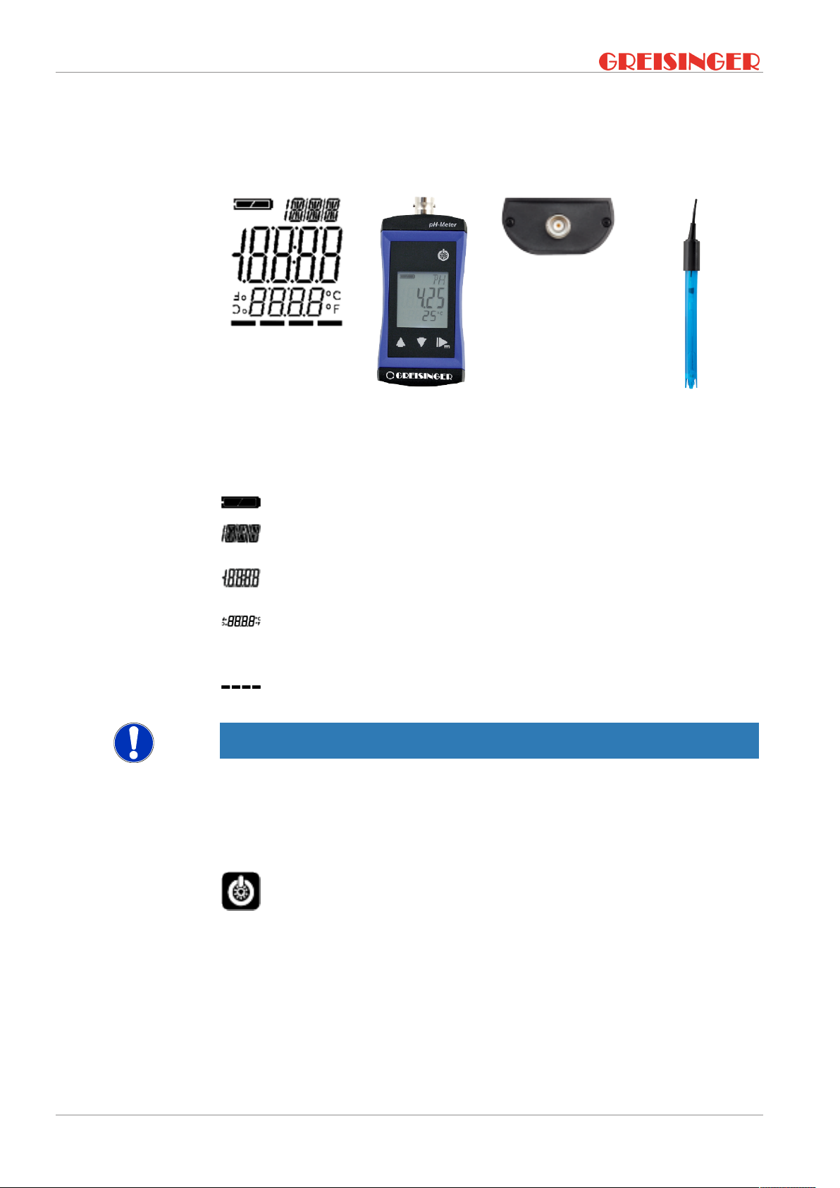
4 The product at a glance
4.1 The G 1500
LCD Display
BNC connection
4.2 Display elements
Display
Battery indicator Evaluation of the battery status
Unit display Display of units, if applicable, with unstable symbol
Main display Measurement of the current pH value or value for
Auxiliary display Corresponding temperature for the displayed pH
Bar graph Progress for calibration and visualisation of the
NOTE
The unit display shows a rotating circle segment in the first position as long as the
measurement is unstable, if the position is unoccupied by the unit display.
G 1500
or type of mode, min/max/hold
min/max/hold
value with unit. Measured temperatures are displayed with a decimal place, adjusted without.
electrode evaluation
GE 114
4.3 Operating elements
On / Off button
Press briefly Switch on the product
Activate / deactivate lighting
Long press Switch off the product
Reject changes in a menu
10 / 34 B-H86.0.11.DB2-1.0
Page 11
G 1500 The product at a glance | 4
Up / Down button
Press briefly Display of the min/max value
Change value of the selected parameter
Long press Reset the min/max value of the current measure-
ment
Both simultaneously Rotate display, overhead display
Function key
Press briefly Freeze measurement
Return to measurement display
Call up next parameter
Long press, 2s
Start menu configuration, (ONF appears in the display
4.4 Connections
BNC connection Connection for pH electrode
CAUTION
Ensuring water tightness!
The product guarantees protection from spray water, rain or accidental immersion in
water. This protection for the plug connector is only guaranteed when plugged in.
Moisture or contaminants on the contacts can result in incorrect measurement results.
– Protect contacts from soiling and moisture!
– Dry off damp plug connectors as quickly as possible!
Un/locking with rotating ring on the cable plug
B-H86.0.11.DB2-1.0 11 / 34
Page 12

5 | Bases for measurement G 1500
5 Bases for measurement
5.1 pH measurement
5.1.1 Explanation
The pH value describes the acidic or alkaline behaviour of an aqueous solution. A pH
value below 7 is acidic, a value above 7 is alkaline. A pH value of 7 is neutral.
The pH measurement is very precise, but also sensitive. The measured signals are
very weak and high-ohmic. This is the case, in particularly in low-ion media.
NOTE
In order to detect the pH value of a solution, it should always be recorded together
with the measurement temperature, because most liquids change their pH value with
the temperature.
The following must be observed:
– avoid interference, electrostatic charges, etc.
– keep plug contacts clean and dry
– prevent electrodes which do not have any special waterproof versions from exten-
ded immersion above the shaft
– calibrate electrodes sufficiently often. The can range from every hour to several
weeks, depending on the electrode and the application
– Use a suitable electrode
5.1.2 pH electrode
NOTE
Normally, so-called pH single-rod measuring chains are used. They include all necessary components that are integrated in an electrode.
12 / 34 B-H86.0.11.DB2-1.0
Page 13

5.1.3 Design
G 1500 Bases for measurement | 5
1. Coaxial cable
2. Reference electrode
3. Measuring electrode
4. Refill opening
5. Electrolyte
6. Internal buffer
7. Diaphragm
8. Glass membrane / source layer
Fig.5:
The diaphragm, which establishes a connection between the electrolyte and the liquid
to be measured, can be designed in different ways. Clogging or soiling of the diaphragm is a frequent cause of a malfunctioning or sluggish electrode. Always handle
the glass membrane with extreme care. The so-called source layer forms there. This
is crucial for the measurement and must always be kept moist.
There are also electrodes with integrated temperature sensors.
pH electrode
5.1.4 Further information
A pH electrode is a wear part. If the signal is very slow or the required values are no
longer observed after careful cleaning and possible regeneration, the electrode must
be replaced. When using the electrodes, be aware that various substances in aqueous
solutions can corrode glass and that chemicals can produce a chemical reaction with
the KCl solution in the electrode, which can result in blockage of the diaphragm.
– In solutions that contain proteins, such as for measurements in medical and biolo-
gical applications, KCl can cause denaturation of the protein.
– Coagulated paints
– Solutions that contain high concentrations of silver ions
Substances that accumulate on the glass membrane or the diaphragm affect the
measurement and must be removed regularly. This can be achieved for example with
automatic cleaning systems.
5.1.5 Choosing a pH electrode
The GE 114 WD or GE 100 can be used for most applications. However, some areas
of application require special electrodes.
B-H86.0.11.DB2-1.0 13 / 34
Page 14

5 | Bases for measurement G 1500
– GE 100 BNC is a universal electrode with two ceramic diaphragms and liquid elec-
trolyte.
– GE 101 BNC is preferably used for small sample amounts. It comprises a glass
electrode with two ceramic diaphragms and liquid electrolyte.
– GE 104 BNC is preferably used for measurements in low-ionic media, such as
rainwater, aquarium water and deionised water.
– GE 114 WD is a universally applicable, durable and low-maintenance gel elec-
trode with Pellon diaphragm. It can be used for measurements in drinking water,
swimming pools, aquaria and slightly contaminated waste water.
– GE 117 BNC is a temperature-compensated gel electrode with two ceramic dia-
phragms and PH 13.5 cable screw coupling.
– GE 120 BNC is an insertion electrode and is preferably used for measurements in
cheese, fruit and meat. For measurements in products containing proteins, the
electrode must be cleaned with a special cleaner. For this purpose, we recommend the GRL 100 pepsin cleaning solution.
– GE 125 BNC is a waterproof, universally applicable, durable and low-maintenance
gel electrode with ceramic diaphragm. It can be immersed above the shaft for an
extended time.
– GE 151 BNC is a glass electrode and is preferably used in galvanic applications
for paints and lacquers.
– GE 173 BNC is an alkaline-resistant glass electrode with ground diaphragm and
gel electrolyte for chemical and waste water applications.
5.1.6 Service life
The service life of electrodes is normally at least 8 to 10 months. When cared for properly, this can usually increase to more than 2 years. The actual life will vary depending
on the particular application.
5.1.7 Care and maintenance
NOTE
The glass tip of the electrode with the sensitive hydrated layer must be kept moist, e.g.
with 3 mol/l KCl solution in the storage cap. Accidental drying-out of the electrode can
be reversed under certain circumstances after storage for several hours in 3 mol/l KCl,
but this cannot be guaranteed.
NOTE
The GAK 1400 working and calibration set includes all necessary products for calibration, care and maintenance of the electrode. Normal cleaning takes place with the
GRL 100 pepsin cleaning solution into which the electrode is immersed for 5 minutes
before being rinsed off with clean water.
NOTE
Crystallisation of the 3 mol/l KCL solution is unavoidable. Crystallised potassium chloride on the protective cap and shaft can easily be removed with a fingernail or cloth
and is therefore not a defect or grounds for complaint.
Dirty electrodes must be cleaned. The suitable cleaning agents for the pH glass membrane are listed in the table below.
14 / 34 B-H86.0.11.DB2-1.0
Page 15

G 1500 Bases for measurement | 5
Impurities Cleaners
General residue Mild detergent
Inorganic coatings Commercially available liquid glass clean-
ers
Metal compounds 1 mol/l HCl solution or GRL 100 pepsin
cleaning solution
Oil and grease Special cleaner or solvent
Biological coatings with protein Pepsin cleaning solution GRL 100
Resin lignins Acetone
Extremely resistant residues Hydrogen peroxide or sodium hypochlor-
ide
The material of the pH electrode must always be protected. Plastic shafts must not be
cleaned in solvents, etc. If in doubt, contact the manufacturer to inquire about suitable
cleaners for the existing electrode. This is also important in the case of aggressive
substances or other substances that are not primarily water-based!
B-H86.0.11.DB2-1.0 15 / 34
Page 16

6 | Operation and maintenance G 1500
6 Operation and maintenance
6.1 Operating and maintenance notices
NOTE
The product and electrode must be handled with care and used in accordance with the
technical data. Do not throw or strike.
NOTE
Plugs and sockets must be protected from soiling.
NOTE
If the product is stored at a temperature above 50 °C, or is not used for an extended
period of time, the batteries must be removed. Leaks from the batteries are avoided as
a result.
NOTE
The electrode should be stored in dry rooms at a temperature between 10 °C and 30
°C. If the storage temperature range is exceeded or undercut, the electrode can be
destroyed. It should always be stored wet in 3 mol/l KCl. Extended storage in distilled
or deionised water will result in depletion of the reference electrolytes.
NOTE
The pH electrode included in the scope of supply should be arranged vertically upwards with the connecting cable. A slight angle of inclination does not impair the
measurement.
6.2 Battery
6.2.1 Battery indicator
If the empty frame in the battery display blinks, the batteries are depleted and must be
replaced. However, the device will still operate for a certain length of time.
If the BAT display text appears in the main display, the battery voltage is no longer adequate for operation of the product. The battery is fully depleted.
6.2.2 Changing battery
DANGER
Danger of explosion!
Using damaged or unsuitable batteries can generate heat, which can cause the batteries to crack and possibly explode!
– Only use high-quality and suitable alkaline batteries!
16 / 34 B-H86.0.11.DB2-1.0
Page 17

G 1500 Operation and maintenance | 6
CAUTION
Damage!
If the batteries have different charge levels, leaks and thus damage to the product can
occur.
– Use new, high-quality batteries!
– Do not use different types of batteries!
– Remove depleted batteries and dispose of them at a suitable collection point!
NOTE
Unnecessary screwing places the water-tightness of the product, among other things,
at risk and should be avoided.
NOTE
Read the following handling instructions before replacing batteries and follow them
step by step. If disregarded, the product could be damaged or the protection from
moisture could be diminished.
Description
Prerequisites
Instruction
Outcome of an action
Proceed as follows to replace the batteries.
– The product is switched off.
– A suitable PH1 is available
Fig.6:
The product is now ready for use again.
Changing battery
1. Unscrews the Phillips screws and remove the cover.
2. Carefully replace the two Mignon AA
batteries. Ensure that the polarity is
correct! It must be possible to insert
the batteries in the correct position
without using force.
3. The O-ring must be undamaged, clean
and positioned at the intended depth.
In order to facilitate assembly and
avoid damage, a suitable grease can
be applied.
4. Fit the cover on evenly. The O-ring
must remain at the intended depth!
5. Tighten the Phillips screws.
6.3 Calibration and adjustment
6.3.1 pH calibration
Description
B-H86.0.11.DB2-1.0 17 / 34
In order to obtain reliable measurements, the product and electrode must be aligned
with each other. In pH measurement, this is referred to as a calibration. In order to
conduct a pH measurement, proceed as follows.
For automatic calibration, open the Calibration menu. See Automatic pH calibration
[}p.19].
Page 18

6 | Operation and maintenance G 1500
Prerequisite
Instruction
– The product is switched on.
1. Carefully remove the protective cap from the electrode.
2. Rinse off the electrode with distilled or deionised water.
3. Press function key F1 for 1 second to open the Calibration menu. Start 1.
point calibration? is shown in the display.
4. The calibration is started by pressing function key F2. Clean 1. point elec-
trode and immerse in buffer OK to start is shown in the display.
5. The cleaning is started by pressing function key F2. 1. point calibration
in progress please wait is displayed.
6. Follow the instructions of the product.
7. After successful completion, Start 2. point calibration? is shown in the
display. Repeat this process depending on which point calibration you would like
to perform.
8. Otherwise an error description is shown in the display and the calibration is cancelled.
9. You can perform a maximum 5-point calibration.
NOTE
The sensor quality is indicated in the large display. If it is less than 10%, the sensor
should first be cleaned thoroughly and then wait. If a low percentage is still shown
after calibration, the sensor must be replaced.
Outcome of an action
6.3.1.1 Explanation
Now, the product can be calibrated.
For this purpose, also refer to
2 Automatic pH calibration [}19]
The following steps describe how to calibrate the product.
To achieve a precise measurement, observe the following points.
NOTE
If possible, the calibration range should overlap the measuring range. To achieve this,
it is recommended to use buffer solutions for measurements as follows:
– below pH 7 uses pH 7.0 and pH 4.0 buffer
– above pH 7 uses pH 7.0 and pH 10.0 buffer
NOTE
Calibrations are only possible in a temperature range from 0 °C to 60 °C! We recommend performing calibration at temperatures between 10 °C and 40 °C.
NOTE
Calibration should be conducted at the same temperature used for the measurement
in the medium. To equalize the temperatures of the buffer solutions and electrode,
they should be stored together for a while in a place that is protected against draught.
18 / 34 B-H86.0.11.DB2-1.0
Page 19

Description
G 1500 Operation and maintenance | 6
NOTE
Measure the temperature of the buffer solution with a thermometer. The exact value of
the buffer solution is temperature dependent and can be determined based on the
tables provided.
NOTE
Always use fresh buffer solutions!
6.3.1.2 Buffer solutions
At least one buffer solution is required to calibrate the product. In the process, you
have the option of using a ready-to-use PHL buffer solution or mixing the solution
yourself with GPH buffer capsules - refer to the instructions.
Colour 10 °C 20 °C 25 °C 30 °C 40 °C
PHL 4.0 Red 4.02 4.00 4.01 4.01 4.01
PHL 7.0 Green 7.06 7.02 7.00 6.99 6.97
PHL 10.0 Blue 10.18 10.07 10.01 9.97 9.89
Prerequisite
Instruction
Outcome of an action
Ready-to-use buffer solutions in 250 ml dosing bottles with a dosing volume of 20 to 25 ml.
– Plastic bottle
– approx. 100 ml of distilled water
– Buffer capsule
Colour 10 °C 20 °C 25 °C 30 °C 40 °C
GPH 4.0 Orange 3.99 3.99 4.01 4.01 4.03
GPH 7.0 Green 7.06 7.01 7.00 6.99 6.98
GPH 10.0 Blue 10.18 10.06 10.01 9.97 9.89
GPH 12.0 White 12.35 12.14 12.00 11.89 11.71
Buffer capsules for 100 ml buffer solution
1. Fill a plastic bottle with approx. 100 ml of distilled water.
2. Open the buffer capsule carefully by twisting the capsule halves and pulling. It
should be ensured that nothing is spilled. They can also be used without opening
them; opening the capsules only reduces to time for dissolving.
3. Place the buffer capsule and its contents in the plastic bottle.
4. Wait at least 3 hours.
5. Shake well before using for the first time.
Then you can begin with calibration of the product.
6.3.1.3 Automatic pH calibration
Description
Prerequisite
B-H86.0.11.DB2-1.0 19 / 34
The following steps describe how to calibrate the product automatically.
– The product is switched on.
– The pH electrode is inserted in the product.
– Ready-to-use GPH 7.0 buffer solution.
– Ready-to-use GPH 4.0 or GPH 10.0 buffer solution.
Page 20

6 | Operation and maintenance G 1500
NOTE
Automatic calibration can also be carried out with the pre-mixed PHL buffer solutions.
Since the temperature compensation relates to the GPH capsules, an error of a few
hundredths pH should be taken into account, depending on the temperature. Refer
also to the differences in the tables of the buffer solutions in Buffer solutions [}p.19].
Instruction
Outcome of an action
1. Press the Function key for 4 seconds to open the Calibration menu. (AL appears in
the display.
2. Release the Function key.
3. PK 7 appears in the display.
4. Place the electrode in the GPH 7.0 buffer solution.
5. The product determines the correct value automatically. If the value is determined,
the display flashes to indicate a change to the next calibration point.
6. Enter the temperature of the buffer solution by pressing the Up key and Down key
and confirm the entry by pressing the Function key again.
7. PK 4 and PK 10 alternate in the display.
8. Then, rinse the electrode with distilled or deionised water.
9. Place the electrode in the second buffer solution. The product recognises whether
it is a PK 4 or PK 10 buffer solution automatically.
10. Enter the temperature of the buffer solution by pressing the Up key and Down key
and confirm the entry by pressing the Function key again.
11. Then, rinse the electrode again with distilled or deionised water.
After successful completion of the calibration the assessment of the electrode condition is displayed briefly in percent. Then, the current measurement is shown in the display again. A low value can be the result of the age of the electrode, contaminated or
old buffer solutions or impurities on the BNC connector.
Description
Prerequisite
Instruction
If the calibration is not completed successfully an error message is displayed. (AL ERR.
appears in the display. See Error and system messages [}p.27]. Confirm the error
message pressing the Function key. The product restarts and the standard value for
the zero point and gradient are restored.
For this purpose, also refer to
2 Buffer solutions [}19]
6.3.1.4 Manual 1-point calibration
The following steps describe how to perform a 1-point pH calibration.
NOTE
A 1-point calibration is only advantageous if measurement takes place in a narrow
range around the calibration point. A reliable electrode evaluation is not possible in
this case. We recommend conducting a 2-point calibration, because a 1-point calibration only entails a shift of the zero point.
– An arbitrary buffer solution is available.
1. Press the Function key for 2 seconds to open the Configuration menu.
2. (ONF appears in the display. Release the Function key.
3. The parameter SET.T appears if the temperature sensor is not plugged in. If the
temperature sensor is plugged in, you jump to the next point.
20 / 34 B-H86.0.11.DB2-1.0
Page 21

Outcome of an action
6.3.1.5 Manual 2-point calibration
Description
Prerequisite
Instruction
G 1500 Operation and maintenance | 6
4. Enter the temperature of the buffer solution by pressing the Up button and Down
button and confirm the entry by pressing the Function key again.
5. The PK.OF parameter appears in the display.
6. Place the electrode in the buffer solution.
7. Wait until the display value is stable.
8. Adjust the value corresponding to the buffer solution with the Up button and Down
button and confirm the entry by pressing the Function key again for 2 seconds.
9. Then, rinse the electrode again with distilled or deionised water.
After successful completion of the calibration the assessment of the electrode condition is displayed briefly in percent. Then, the current measurement is shown in the display again. A low value can be the result of the age of the electrode, contaminated or
old buffer solutions or impurities on the BNC connector.
If the calibration is not completed successfully an error message is displayed. (AL ERR.
appears in the display. See Error and system messages [}p.27].
For this purpose, also refer to
2 Error and system messages [}27]
The following steps describe how to perform a 2-point pH calibration.
– A buffer solution with a value between pH 6.75 and pH 7.25 is available.
– A second buffer solution with a value below pH 6 and above pH 8 is available.
1. Press the Function key for 2 seconds to open the Configuration menu.
2. (ONF appears in the display. Release the Function key.
3. The parameter SET.T appears if the temperature sensor is not plugged in. If the
temperature sensor is plugged in, you jump to the next point.
4. Enter the temperature of the buffer solution by pressing the Up button and Down
button and confirm the entry by pressing the Function key again.
5. The PK.OF parameter appears in the display.
6. Place the electrode in the buffer solution with a value between pH 6.75 and pH
7.25.
7. Wait until the display value is stable.
8. Adjust the value corresponding to the buffer solution with the Up button and Down
button and confirm the entry by pressing the Function key.
9. The PK.SL parameter appears in the display.
10. Place the electrode in the second buffer solution with a value below pH 6 or above
pH 8.
NOTE
A gradient compensation with buffer solutions between pH 6 and pH 8 is not possible.
With entry of the compensation value, the resulting gradient value is calculated imme-
diately and (AL ERR.2 or (AL ERR.3 appears in the display instead of the measurement of
the values are invalid.
11. Wait until the display value is stable.
12. Adjust the value corresponding to the buffer solution with the Up button and Down
button and confirm the entry by pressing the Function key.
13. Then, rinse the electrode again with distilled or deionised water.
B-H86.0.11.DB2-1.0 21 / 34
Page 22

6 | Operation and maintenance G 1500
Outcome of an action
6.4.1 Certificates
After successful completion of the calibration the assessment of the electrode condition is displayed briefly in percent. Then, the current measurement is shown in the display again. A low value can be the result of the age of the electrode, contaminated or
old buffer solutions or impurities on the BNC connector.
If the calibration is not completed successfully an error message is displayed. (AL ERR.
appears in the display. See Error and system messages [}p.27]. Confirm the error
message pressing the Function key. The product restarts and the standard value for
the zero point and gradient are restored.
For this purpose, also refer to
2 Error and system messages [}27]
6.4 Calibration and adjustment service
The certificates are categorised as ISO calibration certificates and DAkkS calibration
certificates. The purpose of the calibration is to verify the precision of the measuring
device by comparing it with a traceable reference.
NOTE
The ISO standard 9001 is applied for the calibration certificates. These certificates
area affordable alternative to the DAkkS calibration certificates and provide information of the traceable reference, a list of individual values and documentation.
NOTE
The DAkkS calibration is based on DIN EN ISO/17025, the accreditation basis recognised worldwide. These certificates offer high-quality calibration and consistently high
quality. DAkkS calibration certificates can only be issued by accredited calibration
laboratories which have demonstrated their expertise in accordance with DIN EN ISO/
IEC 17025. The DAkkS calibration includes any necessary adjustment with the purpose of minimising a deviation of the measuring device.
DAkkS calibration certificates are accompanied with a list of individual measurements
before and after the adjustment, documentation and, if applicable, graphic representation, calculation of the expanded measuring uncertainty and traceability to the national
standard.
NOTE
The product is delivered with a test report. This confirms that the measuring device
has been adjusted and tested.
NOTE
Only the manufacturer can check the basic settings and make corrections if necessary.
22 / 34 B-H86.0.11.DB2-1.0
Page 23
7.1.1 Explanation
Description
Prerequisite
Instruction
Outcome of an action
G 1500 Operation | 7
7 Operation
7.1 Commissioning
The product is switched on with the On/Off button. It may be necessary to configure
the product after switching on. See Configuration [}p.23].
– Sufficiently full batteries are inserted in the product.
– A suitable pH electrode is plugged in.
– Press the On/Off button.
Information about the configuration of the product appears in the display.
POFF
T.OF
T.SL
(AL
– The product is now ready for measurement.
Automatic shutoff
Zero point correction
Gradient correction
Calibration Blinks if no valid calibration is available
NOTE
The product must be calibrated to the electrode prior to starting the measurement. If
the electrode is chosen, re-calibration is necessary. See Calibration and adjustment
service [}p.22].
7.2 Configuration
7.2.1 Explanation
The following steps describe how to adapt the product for your purposes.
Automatic shut-off activated. The product is
switched off if no buttons have been pressed after
the adjusted time
If a zero point correction of the temperature sensor
was made
If a gradient correction of the temperature sensor
was made
NOTE
There are various configuration parameters available depending on the product version and configuration. They can differ depending on the product version and configuration.
7.2.2 Opening the configuration menu
Description
Prerequisite
Instruction
B-H86.0.11.DB2-1.0 23 / 34
In order to configure the product, you must first open the Configuration menu. The
menu is opened as shown in the illustration.
– The product is switched on.
1. Press the Function key for 2 seconds to open the Configuration menu.
2. (ONF appears in the display. Release the function key.
Page 24

7 | Operation G 1500
3. By briefly pressing the Function key, you can scroll through the parameters. Select
the parameter you would like to configure.
4. When you have selected the desired parameter, change the parameter to the desired value with the Up button and the Down button.
5. The changes are saved after running through the entire Configuration menu. STOR
appears in the display. The Configuration menu can be exited from any arbitrary
parameter by pressing and holding the Function key for 2 seconds. The changes
made up that point are saved.
Representation
Outcome of an action
Call up menu Next parameter Change value Save changes Discard
2s Press: Single
step
Hold: Rapid
change
The Configuration menu is closed after the last parameter.
NOTE
changes
2s 2s
Product is
switched off
Description
Prerequisite
Instruction
Representation
If the product is switched off without saving the configuration, the last save value is reproduced on the next start-up of the product.
7.2.3 Configuring parameters of the configuration menu
The following representation shows the available parameters and various configuration options.
– The Configuration menu is open. See Opening the configuration menu [}p.23].
1. Select the desired parameter you would like to configure.
2. Adjust the desired configuration in the selected parameter with the Up button and
Down button.
3. The available configuration options are listed for each parameter in the following
representation.
Parameter Values Meaning
Setting the temperature
Setting the zero point
PK.OF
Current measurement
Setting the gradient
PK.SL
Current measurement
24 / 34 B-H86.0.11.DB2-1.0
Setting of the zero point for calibration of the pH
measurement. If a calibration cannot be carried out,
continue with the function key
Setting of the gradient for calibration of the pH
measurement. If a calibration cannot be carried out,
continue with the function key
Page 25

Temperature unit
UN,T
Shut-off time
POFF
Backlighting
L,TE
°(
°F
OFF
15 30 60 120 240
OFF
15 30 60 120 240
ON
G 1500 Operation | 7
Temperature display in °C
Temperature display in °F
No automatic shut-off
Automatic shut-off after a selected time in minutes,
during which no buttons have been pressed
Backlighting deactivated
Automatic shut-off of the backlighting after a selected time in seconds, during which no buttons have
been pressed
No automatic shut-off of the backlighting
Outcome of an action
7.2.4 Adjustment of the measuring input
Description
Prerequisites
Instruction
Factory settings
IN,T
NO
YES Reset product to factory settings. IN,T DONE appears
The changed value is saved and the Configuration menu is closed. STOR appears in
the display. If necessary, the product is restarted automatically in order to adopt the
changed values.
Use current configuration
in the display
NOTE
The configuration is closed if no button is pressed for 2 minutes. Any changes made
up to that point are not saved. C.END appears in the display.
There is no active timeout with the parameters PK.OF and PK.SL.
The temperature input can be adjusted with the zero point correction and the gradient
correction. If an adjustment is made, you change the pre-adjusted factory settings.
This is signalled with the T.OF or T.SL when the product is switched on. The standard
settings of the zero point value and the gradient value is 0.00. It signals that no correc-
tion is made.
In order to adjust the product, you must first open the Adjustment menu. The menu is
opened as shown in the illustration.
– Sufficiently full batteries are inserted in the product.
– The product is switched off.
– Ice water, regulated precision water baths or a water bath with a reference meas-
urement are available as a reference.
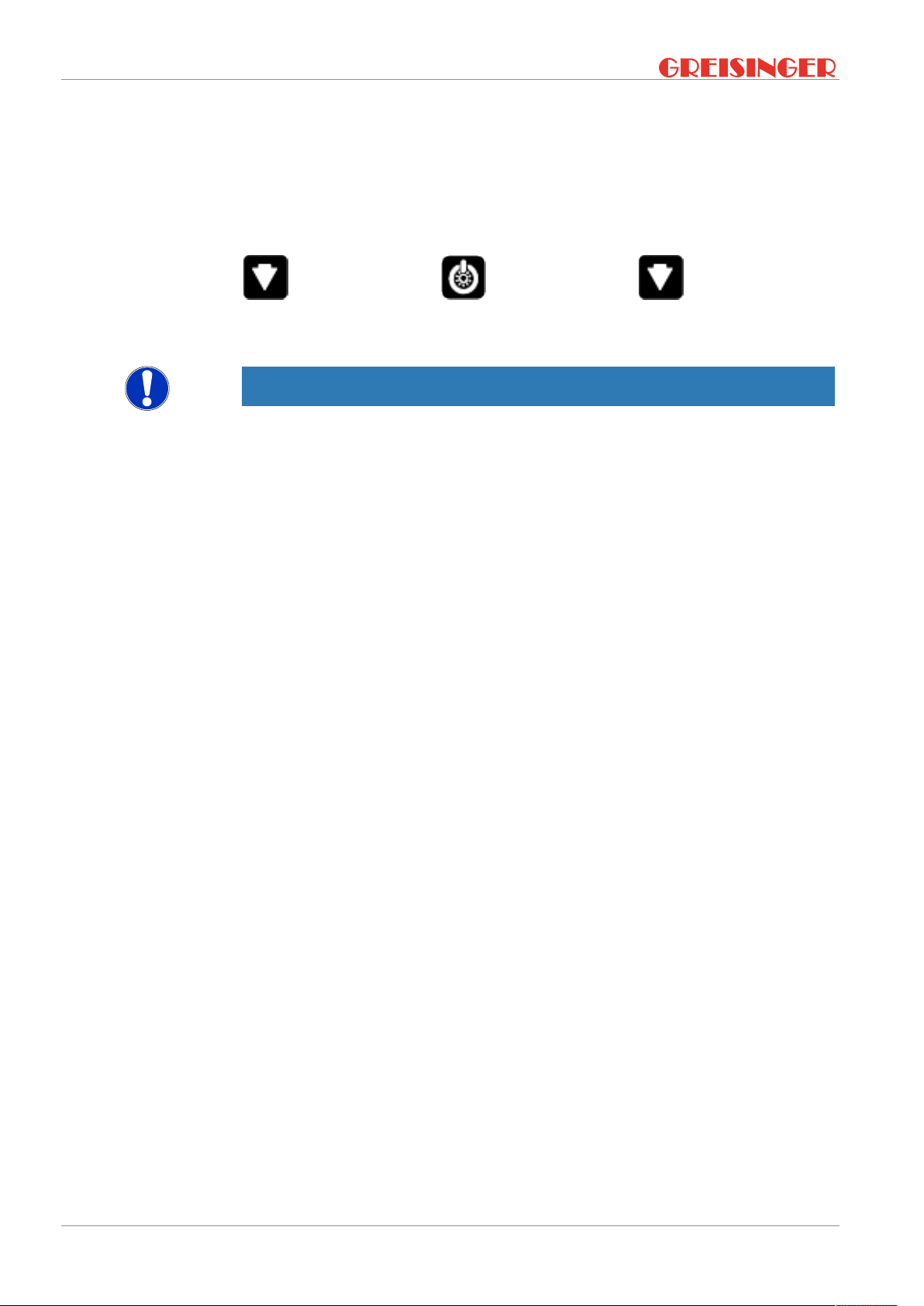
1. Press and hold the Down button.
2. Press the On/Off button to switch on the product and open the Configuration
menu. Release the Down button. The display shows the first parameter.
B-H86.0.11.DB2-1.0 25 / 34
Page 26
7 | Operation G 1500
3. By briefly pressing the Function key, you can scroll through the parameters. Select
the parameter you would like to configure.
4. When you have selected the desired parameter, change the parameter to the desired value with the Up button and the Down button.
5. In order to save the new parameter value, press and hold the Function key for
longer than 1 second.
Representation
Outcome of an action
Call up menu
Hold Release
The Configuration menu is closed after the last parameter.
NOTE
If the product is switched off without saving the configuration, the last save value is reproduced on the next start-up of the product.
26 / 34 B-H86.0.11.DB2-1.0
Page 27

G 1500 Error and system messages | 8
8 Error and system messages
Display Meaning Possible causes Remedy
SENS ERRO
>(AL<
No display,
unclear characters or no
response
when buttons are
pressed
BAT
BAT LO
(AL ERR.1
(AL ERR.2
(AL ERR.3
(AL ERR.4
(AL ERR.5
ERR.1
ERR.2
No probe or sensor
connected
Sensor or probe defect
Measuring range exceeded or undercut
Error during the last
calibration
Battery depleted
System error
Product is defective
Battery depleted Battery depleted Replace battery
Battery depleted Battery depleted Replace battery
Neutral buffer not allowed
Slope is too low Incorrect buffer solu-
Slope is too high Incorrect buffer solu-
Incorrect calibration
temperature
Time exceeded during automatic calibration
Measuring range exceeded
Measuring range is
undercut
Sensor or probe
missing
Defective sensor or
probe
Incorrect sensor
type selected
Faulty calibration Conduct a new calibration
Battery depleted
Error in the product
Product is defective
Incorrect buffer solution used
Buffer solution is
contaminated
Electrode contaminated or defective
tion used
Buffer solution is
contaminated
Electrode contaminated or defective
tion used
Buffer solution is
contaminated
Electrode contaminated or defective
Temperature too low
or too high
Unstable electrode
signal
Buffer solution is
contaminated
Measurement too
high
Incorrect electrode
connected
Electrode or product
defect
Measurement too
low
Connect sensor or probe
Connect different sensor or
probe
Readjust measuring range
Replace battery
Send in for repair
Use fresh buffer solution
Clean electrode, re-calibrate
Replace electrode
Use fresh buffer solution
Clean electrode, re-calibrate
Replace electrode
Use fresh buffer solution
Clean electrode, re-calibrate
Replace electrode
Range of 0..60 °C
Stirring of the buffer solution
Clean the electrode
Use fresh buffer solution
Restart calibration
The measurement is above
the permissible range
Check electrode
Send in for repair
The measurement is below
the permissible range
B-H86.0.11.DB2-1.0 27 / 34
Page 28

8 | Error and system messages G 1500
SYS ERR
Incorrect electrode
connected
Check electrode
Send in for repair
Electrode or product
defect
System error Error in the product Switch product on/off
Replace batteries
Send in for repair
28 / 34 B-H86.0.11.DB2-1.0
Page 29

G 1500 Disposal | 9
9 Disposal
Separation by material and recycling of device components and packaging must take
place at the time of disposal. The valid regional statutory regulations and directives
applicable at the time must be observed.
NOTE
The device must not be disposed of with household waste. Return it to us, freight prepaid. We will then arrange for the proper and environmentally-friendly disposal.
Private end users in Germany have the possibility of dropping off the product at the
municipal collection centre.
Please dispose of empty batteries at the collection points intended for this purpose.
NOTE
Fill in the return form available from the information base online at www.ghm-group.de
and sent it in with the product.
B-H86.0.11.DB2-1.0 29 / 34
Page 30

10 | Technical data G 1500
10 Technical data
Measuring range pH 0.00 .. 14.00 pH
Temperature compensation -5 .. 150 °C (or 23 .. 302 °F)
Accuracy pH (device) ± 0.02 pH ± 1 digit
Nominal temperature 25°C
Input resistance pH ca. 1012 Ohm
Measuring cycle approx. 2 measurements per second
Connections pH BNC connection for pH electrode
Display 3-line segment LCD, additional symbols, illuminated (adjustable white,
permanent illumination)
Additional functions Min/Max/Hold
pH calibration Manual 1- or 2-point or automatic 2-point calibration
Housing Break-proof ABS housing
Protection rating IP65 / IP67 (only with sensors identified as waterproof in the connected
state for devices with BNC connection)
Dimensions L*W*H
[mm] and weight
Operating conditions -20 to 50 °C; 0 to 95 % r.h. (temporarily 100 % r.h.)
Storage temperature -20 to 70 °C
Current sup-
ply
Auto-power-OFF function The device switches off automatically if this is activated
Directives and standards The devices conform to the following Directives of the Council for the
Current requirement/
battery life
Battery indicator 4-stage battery status indicator,
108 * 54 * 28 mm without BNC plug
130 g, incl. battery, without electrode
190 g, incl. battery and electrode
2*AA battery (included in the scope of delivery)
approx. 0.7 mA, approx. 2.5 mA with lighting
Service life > 3000 hours with alkaline batteries (without backlighting)
Replacement indicator for depleted batteries: "BAT"
harmonisation of legal regulations of the Member States:
2014/30/EU EMC Directive
2011/65/EU RoHS
Applied harmonised standards:
EN 61326-1:2013 Emission limits: Class B
Immunity according to Table 2
Additional errors: < 0.5 % FS
EN 50581:2012
30 / 34 B-H86.0.11.DB2-1.0
Page 31

Article
G 1500 Spare parts and accessories | 11
11 Spare parts and accessories
A selection of spare parts and accessories for this product is listed below.
Number Name Description
610049 Mignon batteryAAMignon AA spare battery
603523 GAK 1400 Working and calibration set
600704 GE 100 Universal pH electrode with BNC connection
600693 GE 101 Ø 0.6 mm tip pH electrode with BNC connection
602063 GE 104 pH electrode for low-ionic media with BNC connection
600713 GE 108 Low-maintenance pH electrode with BNC connection
606089 GE 108 Low-maintenance pH electrode with S7 connection
604701 GE 114 Affordable, low-maintenance pH electrode with BNC
connection
600698 GE 120 Ø 13 mm insertion pH electrode with BNC connection
600727 GE 151 Chemically-resistant pH electrode with BNC connec-
tion
606375 GE 171 Sterilisable pH electrode for extreme conditions with
S7 connection
600735 GE 173 Alkali-resistant pH electrode with BNC connection
606572 GE 173 Alkali-resistant pH electrode with S7 connection
601996 GEAK-2S7-BNC Adapter cable S7-BNC, 2 m
601998 GEAK-2S7-BNC Adapter cable S7-BNC, 5 m
601060 GKK 1100 Case with nap foam, 340 x 275 x 83 mm
601056 GKK 252 Case with nap foam, 235 x 185 x 48 mm
601417 GPF 100 Plastic bottle with wide neck, 100 ml
602619 GPH 10.0 / 10 10 buffer capsules, pH 10.0
602618 GPH 10.0 / 5 5 buffer capsules, pH 10.0
602621 GPH 12.0 / 10 10 buffer capsules, pH 12.0
602620 GPH 12.0 / 5 5 buffer capsules, pH 12.0
602615 GPH 4.0 / 10 10 buffer capsules, pH 4.0
602614 GPH 4.0 / 5 5 buffer capsules, pH 4.0
602617 GPH 7.0 / 10 10 buffer capsules, pH 7.0
602616 GPH 7.0 / 5 5 buffer capsules, pH 7.0
601422 GRL 100 Pepsin cleaning solution, 100 ml
602914 GWA1Z Threaded adapter PG13.5 to G1
602477 KCL 3 M 3 mol KCL electrolyte for refilling, 100 ml
603205 PG 13.5 Plug-in thread adapter for pressureless insertion of all
electrodes
601373 PHL 10 Ready-to-use buffer solution, pH 10.01 / 25 °C, 250 ml
601370 PHL 4 Ready-to-use buffer solution, pH 4.01 / 25 °C, 250 ml
601371 PHL 7 Ready-to-use buffer solution, pH 7.00 / 25 °C, 250 ml
611373 ST-G1000 Device protection bag with 1 round cut-out
A complete list of all accessories and spare parts is available in our product catalogue
or on our home page. We can also provide further information by phone.
Contact
B-H86.0.11.DB2-1.0 31 / 34
Internet:www.greisinger.de
Tel: +49 94029383-52
Page 32

12 | Service G 1500
12 Service
12.1 Manufacturer
If you have any questions, please do not hesitate to contact us:
Contact
12.2 Repairs processing
Open hours and contact
GHM Messtechnik GmbH
GHM GROUP - Greisinger
Hans-Sachs-Str. 26
93128 Regenstauf | GERMANY
Email: info@greisinger.de | www.greisinger.de
WEEE reg. no. DE 93889386
Defective products are repaired professionally and quickly in our service centre.
Monday to Thursday from 8:00 to 16:00
Friday from 8:00 to 13:00
GHM Messtechnik GmbH
GHM GROUP - Greisinger
Hans-Sachs-Str.26
Service Centre
93128 Regenstauf | GERMANY
Tel: +49 94029383-39
Fax: +49 94029383-33
service@greisinger.de
NOTE
Fill in the return form available from the information base online at www.ghm-group.de
and sent it in with the product.
12.3 Sales offices
North Sales Office
Post code: 00000 – 25999 | 27000 – 34999
37000 – 39999 | 98000 – 99999
Email: vertrieb-nord@ghm-messtechnik.de
Tel: +49 4067073-0
Fax: +49 4067073-288
West Sales Office
32 / 34 B-H86.0.11.DB2-1.0
Page 33

G 1500 Service | 12
Post code: 26000 – 26999 | 35000 – 36999
40000 – 69999
Email: vertrieb-west@ghm-messtechnik.de
Tel: +49 2191 9672-0
Fax: +49 2191 9672-40
South Sales Office
Post code: 70000 – 97999
Email: vertrieb-sued@ghm-messtechnik.de
Tel: +49 9402 9383-52
Fax: +49 9402 9383-33
12.4 Sales subsidiaries
Austria
GHM Messtechnik GmbH
Office Austria
Breitenseer Str. 76/1/36
1140 Vienna | AUSTRIA
Phone +43 660 7335603
a.froestl@ghm-messtechnik.de
Denmark
GHM Maaleteknik ApS
Maarslet Byvej 2
8320 Maarslet | DENMARK
Phone +45 646492- 00
Fax +45 646492- 01
info@ghm.dk | www.ghm.dk
Italy for Greisinger & Delta OHM
GHM GROUP – Delta OHM
Via Marconi 5
35030 Caselle di Selvazzano
Padova (PD) | ITALY
Phone +39 049 8977150
a.casati@ghm-messtechnik.de
Brazil & Latin America
GHM Messtechnik do Brasil Ltda
Av. José de Souza Campos, 1073, cj 06
Campinas, SP
13025 320 | BRAZIL
Phone +55 19 3304 3408
Info@grupoghm.com.br
France
GHM GROUP France SAS
Parc des Pivolles
9 Rue de Catalogne
69150 Décines-Charpieu (Lyon) | FRANCE
Phone +33 4 72 37 45 30
a.jouanilou@ghm-group.fr
Italy for Honsberg, Martens, Val.co
GHM GROUP – Val.co
Via Rovereto 9/11
20014 S. Ilario di Nerviano
Milano (MI) | ITALY
Phone +39 0331 53 59 20
alessandro.perego@valco.it
Czech Republic / Slovakia
GHM Greisinger s.r.o.
Ovci hajek 2 / 2153
158 00 Prague 5
Nove Butovice | CZECH REPUBLIC
Phone +420 251 613828
Fax +420 251 612607
info@greisinger.cz | www.greisinger.cz
India
GHM Messtechnik India Pvt Ltd.
209 | Udyog Bhavan | Sonowala Road
Gregaon ( E ) | Mumbai - 400 063
INDIA
Phone +91 22 40236235
info@ghmgroup.in | www.ghmgroup.in
Netherlands
GHM Meettechniek BV
Zeeltweg 30
3755 KA Eemnes | NETHERLANDS
Phone +31 35 53805-40
Fax +31 35 53805-41
info@ghm-nl.com | www.ghm-nl.com
South Africa
GHM Messtechnik SA (Pty) Ltd
16 Olivier Street
Verwoerdpark, Alberton 1453
SOUTH AFRICA
Phone +27 74 4590040
j.grobler@ghm-sa.co.za
B-H86.0.11.DB2-1.0 33 / 34
Page 34

 Loading...