

Page 1
Operating manual
G 1410
Handheld conductivity measuring
device
Permanently connected graphite 2-pole
measuring cell
Waterproof
Precise and fast
EN
Page 2

Table of contents
2 / 28 B-H87.0.01.DB2-1.0
Table of contents
1 About this documentation ................................................................................................................. 4
1.1 Foreword............................................................................................................................................... 4
1.2 Purpose of the document...................................................................................................................... 4
1.3 Legal notices......................................................................................................................................... 4
1.4 Correctness of content.......................................................................................................................... 4
1.5 Layout of this document........................................................................................................................ 4
1.6 Further information ............................................................................................................................... 5
2 Safety ................................................................................................................................................... 6
2.1 Explanation of safety symbols .............................................................................................................. 6
2.2 Foreseeable misuse ............................................................................................................................. 6
2.3 Safety instructions ................................................................................................................................ 6
2.4 Intended use ......................................................................................................................................... 7
2.5 Qualified personnel............................................................................................................................... 7
3 Description .......................................................................................................................................... 8
3.1 Scope of delivery .................................................................................................................................. 8
3.2 Job description...................................................................................................................................... 8
4 The product at a glance ..................................................................................................................... 9
4.1 The G 1410........................................................................................................................................... 9
4.2 Display elements .................................................................................................................................. 9
4.3 Operating elements .............................................................................................................................. 9
5 Bases for measurement ................................................................................................................... 11
5.1 Conductivity principles ........................................................................................................................ 11
5.2 Conductivity measurement ................................................................................................................. 11
5.3 Total dissolved solids / TDS measurement ........................................................................................ 11
5.4 Salt content / salinity measurement.................................................................................................... 12
5.5 Electrodes / measuring cell................................................................................................................. 12
5.5.1 Design and selection .......................................................................................................................... 12
5.5.2 Calibration / adjustment of the measuring cell.................................................................................... 12
5.6 Temperature compensation................................................................................................................ 13
5.6.1 NLF temperature compensation according to EN 27888.................................................................... 13
6 Maintenance ...................................................................................................................................... 14
6.1 Operating and maintenance notices ................................................................................................... 14
6.2 Battery ................................................................................................................................................ 14
6.2.1 Battery indicator.................................................................................................................................. 14
6.2.2 Changing battery ................................................................................................................................ 14
6.3 Calibration and adjustment service..................................................................................................... 15
6.3.1 Certificates.......................................................................................................................................... 15
7 Operation........................................................................................................................................... 17
7.1 Commissioning ................................................................................................................................... 17
7.1.1 Explanation ......................................................................................................................................... 17
7.2 Configuration ...................................................................................................................................... 17
7.2.1 Explanation ......................................................................................................................................... 17
7.2.2 Opening the configuration menu......................................................................................................... 17
7.2.3 Configuring parameters of the configuration menu............................................................................. 18
Page 3

Table of contents
B-H87.0.01.DB2-1.0 3 / 28
7.2.4 Adjustment of the measuring input ..................................................................................................... 20
7.2.5 Configuring parameters of the adjustment menu................................................................................ 20
8 Error and system messages............................................................................................................ 23
9 Disposal............................................................................................................................................. 24
10 Technical data................................................................................................................................... 25
11 Spare parts and accessories ........................................................................................................... 26
12 Service ............................................................................................................................................... 27
12.1 Manufacturer....................................................................................................................................... 27
12.2 Repairs ............................................................................................................................................... 27
12.3 Sales subsidiaries............................................................................................................................... 28
Page 4

1 | About this documentation Handheld conductivity measuring device
4 / 28 B-H87.0.01.DB2-1.0
1 About this documentation
1.1 Foreword
Read this document carefully and familiarise yourself with the operation of the product
before you use it. Keep this document ready to hand and in the immediate vicinity of
the product so that it is available to the personnel/user for reference at all times in
case of doubt.
The product was developed according to the state of the art and fulfils the requirements of the applicable European and national Directives. All corresponding documents are available from the manufacturer.
Only technically qualified persons are permitted to carry out commissioning, operation,
maintenance and decommissioning. The qualified personnel must have carefully read
and understood the operating manual before beginning any work.
1.2 Purpose of the document
– This document describes the operation and maintenance of the product.
– Provides important information for working safely and efficiently with the product.
– In addition to the quick reference guide with all relevant legal and safety content in
hard copy, this document is a detailed reference option for the product.
1.3 Legal notices
The liability and warranty of the manufacturer for damages and consequential damages are voided with misuse, disregarding this operating manual, disregarding safety
notices, assignment of inadequately qualified technical personnel and arbitrary modifications of the product.
Only carry out the maintenance and service tasks on this product that are described in
this documentation. In the process, adhere to the specified steps. For your own safety,
only use original spare parts and accessories of the manufacturer. We assume no liability for the use of other products and resulting damage.
This document is entrusted to the recipient for personal use only. Any impermissible
transfer, duplication, translation into other languages or excerpts from this operating
manual are prohibited.
The manufacturer assumes no liability for print errors.
1.4 Correctness of content
The contents of this document were checked for corrected and are subject to a continuous correction and updating process. This does not rule out potential errors. In the
event that errors are discovered or in case of suggestions for improvement, please inform us immediately via the indicated contact information in order to help us make this
document even more user-friendly.
1.5 Layout of this document
Description
Each chapter is explained at the beginning in the description.
Page 5

Handheld conductivity measuring device About this documentation | 1
B-H87.0.01.DB2-1.0 5 / 28
Prerequisite
All mandatory prerequisites are then listed for each step.
Instruction
Tasks to be carried out by the personnel / user are represented as numbered instructions. Adhere to the sequence of the specified instructions.
Representation
Shows an illustrative instruction or a configuration of the product.
Formula
Some instructions include a formula for a general understanding of a configuration,
programming or a setting of the product.
Outcome of an action
Result, consequence or effect of an instruction.
Emphases
In order to simplify legibility and provide a clearer overview, various sections / information are emphasised.
– 1234 Display elements
– Mechanical controls
– Product functions
– Product labels
– Cross-reference [}p.4]
– Foot notes
1.6 Further information
Software version of the product:
– V1.3 or later
For the exact product name, refer to the type plate on the rear side of the product.
NOTE
For information about the software version, press and hold the ON button to switch on
the product for longer than 5 seconds. The series is shown in the main display and the
software version of the product is shown in the secondary display.
Page 6
2 | Safety Handheld conductivity measuring device
6 / 28 B-H87.0.01.DB2-1.0
2 Safety
2.1 Explanation of safety symbols
DANGER
This symbol warns of imminent danger which can result in death, severe bodily injury,
or severe property damage in case of non-observance.
CAUTION
This symbol warns of potential dangers or harmful situations which can cause damage
to the device or to the environment in case of non-observance.
NOTE
This symbol indicates processes which can have a direct influence on operation or
can trigger an unforeseen reaction in case of non-observance.
2.2 Foreseeable misuse
The fault-free function and operational safety of the product can only be guaranteed if
generally applicable safety precautions and the device-specific safety instructions for
this document are observed.
If these notices are disregarded, personal injury or death, as well as property damage
can occur.
DANGER
Incorrect area of application!
In order to prevent erratic behaviour of the product, personal injury or property damage, the product must be used exclusively as described in the chapter Description
[}p.8] in the operating manual.
– Do not use in safety / Emergency Stop devices!
– The product is not suitable for use in explosion-prone areas!
– The product must not be used for diagnostic or other medical purposes on pa-
tients!
– Not suitable for SIL!
2.3 Safety instructions
This product has been designed and tested according to the safety requirements for
electronic measuring devices.
Page 7
Handheld conductivity measuring device Safety | 2
B-H87.0.01.DB2-1.0 7 / 28
CAUTION
Erratic behaviour!
On suspicion that the product can no longer be operated without danger, it must be
decommissioned and prevented from recommissioning with appropriate labelling. The
safety of the user can be impaired by the device if, for example, if it shows visible
damage, it no longer works as specified or if it was stored for an extended period of
time under unsuitable conditions.
– Visual inspection!
– In case of doubt, send the product to the manufacturer for repair or maintenance!
NOTE
If the product is stored at a temperature above 50 °C, or is not used for an extended
period of time, the batteries must be removed. Leaks from the batteries are avoided as
a result.
NOTE
This product does not belong in children's hands!
2.4 Intended use
The product is designed for measuring the conductivity in liquids. The measuring cell
is connected permanently.
See Technical data [}p.25].
2.5 Qualified personnel
For commissioning, operation and maintenance, the relevant personnel must have adequate knowledge of the measuring process and use of the measurements, for which
purpose this document makes a valuable contribution. The instructions in this document must be understood, observed and followed.
In order to ensure that no risks arise from the interpretation of the measurements in
the concrete application, the user must have additional technical knowledge, because
the user is liable in case of damage/danger due to misinterpretation as a result of inadequate technical knowledge.
Page 8

3 | Description Handheld conductivity measuring device
8 / 28 B-H87.0.01.DB2-1.0
3 Description
3.1 Scope of delivery
Please check to ensure the completeness of the product after opening the package.
You should find the following components:
– Quick reference guide
– Handheld measuring device, ready for operation, including batteries
– Permanently connected conductivity measuring cell
– Test report
3.2 Job description
The product offers precision, speed and reliability in a compact, ergonomic housing.
Additional impressive features include the dust-proof and waterproof design in accordance with IP 65/67 and the 3-line illuminated display, which offers overhead display at
the push of a button. The product can be switched on, switched off and configured and
the measurements and parameters can be adjusted and held with the operating elements. The product is equipped with a universal 2-pole graphite conductivity measuring cell for measurement in the range of 0 µS/cm to 100.0 mS/cm. In addition to conductivity, salinity and TDS can be determined.
Page 9
Handheld conductivity measuring device The product at a glance | 4
B-H87.0.01.DB2-1.0 9 / 28
4 The product at a glance
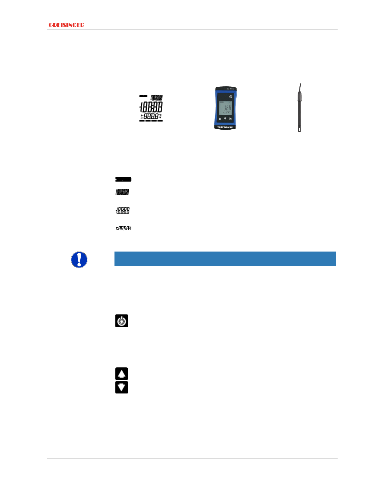
4.1 The G 1410
LCD Display G1410 G1410
4.2 Display elements
Display
Battery indicator Evaluation of the battery status
Unit display Display of units, if applicable, with unstable symbol
or type of mode, min/max/hold
Main display Measurement of the current conductivity value or
value for min/max/hold
Auxiliary display Corresponding temperature value for the value
shown in the main display. If applicable, alternating
with the temperature compensation.
NOTE
The unit display shows a rotating circle segment in the first position as long as the
measurement is unstable, if the position is unoccupied by the unit display.
4.3 Operating elements
On / Off button
Press briefly Switch on the product
Activate / deactivate lighting
Long press Switch off the product
Reject changes in a menu
Up / Down button
Press briefly Display of the min/max value
Change value of the selected parameter
Long press Reset the min/max value of the current measure-
ment
Both simultaneously Rotate display, overhead display
Page 10

4 | The product at a glance Handheld conductivity measuring device
10 / 28 B-H87.0.01.DB2-1.0
Function key
Press briefly Freeze measurement
Return to measurement display
Call up next parameter
Long press, 2s Call up menu and close, changes are saved
Page 11

Handheld conductivity measuring device Bases for measurement | 5
B-H87.0.01.DB2-1.0 11 / 28
5 Bases for measurement
5.1 Conductivity principles
Conductivity γ
Conductivity describes the capability of a material to conduct electrical current. It is
also the inverse of specific resistance. The conductance is the inverse of the measured resistance R.
Formula
γ = l / (R*A)
l = length of the material
A = cross section
R = measured resistance
Unit [γ] = Siemens / metre = S / m
Normally, the values for liquids are specified in µS / cm or in mS / cm.
5.2 Conductivity measurement
The conductivity measurement is a comparatively uncomplicated measurement. The
standard electrodes are stable for correct use for a long time and can be calibrated
over the gradient correction.
Range 1 2 3
0 to 2000 µS/cm 0.00 to 20.00 mS/cm 0 to 200 mS/cm
With the automatic range selection, the range with the best resolution is selected automatically.
5.3 Total dissolved solids / TDS measurement
The total dissolved solids measurement - TDS measurement - determines the total
dissolved solids, which also called evaporation residue, based on the conductivity and
a conversion factor CtdS of the total dissolved solids. Well-suited to conduct simple
concentration measurements of salt solutions. The display shows mg/l
Range 1
0 to 2000 mg/l
Display value TDS = conductivity [in µs/cm, nLF temperature compensation at 25°C] *
CtdS menu entry
With selection of TDS, the necessary temperature compensation is selected automatically. Menu settings for temperature compensation are ignored.
The following approximations apply:
CtdS
0.50 Monovalent salts with 2 ion types = NaCl, KCl or similar
0.50 Natural water of surface water, drinking water
0.65 to 0.70 Salt concentration of aqueous fertiliser solutions
NOTE
These are guideline values for estimates, but are not suitable for precise measurements. The conversion factor for the respective type of solution and the examined
concentration range must be determined for precise measurements. This can take
Page 12

5 | Bases for measurement Handheld conductivity measuring device
12 / 28 B-H87.0.01.DB2-1.0
place with calibration to known comparison solutions or with actual evaporation of a
certain amount of liquid with measured conductivity and subsequent weight of the total
dissolved solids.
5.4 Salt content / salinity measurement
In SAL measuring mode, the salinity, which is the salt content of sea water, is determined. The basis for this is the International Oceanographic Tables, IOT. Standard salt
water has a salinity of 35 ‰, 35 g of salt per 1 kg of sea water. The display in % [g/kg]
normally does not show units. The designation PSU, Practical Salinity Unit, is also
commonly used; the display value is identical. The salinity measurement has temperature compensation, which means the temperature is considered for the display and
has a major influence on the display value; any menu settings regarding temperature
compensation are ignored.
NOTE
The salt composition of different seas is not identical. Depending on the location,
weather, seasons, etc., there are considerable deviations from the 35 ‰ according to
the IOT. The salt composition can also influence the relationship of the salinity display
and the actual amount of salt present.
Corresponding tables are available for many salts in salt water aquarium applications.
Salt weight to salinity according to the IOT or conductivity. In consideration of these
tables, very precise salinity measurements can be conducted.
5.5 Electrodes / measuring cell
5.5.1 Design and selection
There are basically two different types of measuring cells: 2-pole and 4-pole measuring cells. Control and/or evaluation take place in a similar manner; the 4-pole measuring cells can compensate well for polarisation effects and contamination to a certain
degree with the more elaborate measuring processes. The product is equipped with a
permanently connected 2-pole measuring cell.
2-pole measuring cell
4-pole measuring cell
Universal 2-pole graphite measuring cell with wide range of applications, such as fish
husbandry, measurement of surface water and drinking water.
5.5.2 Calibration / adjustment of the measuring cell
In harsh applications and due to ageing processes, the cell constant of measuring
cells changes. Depending on the application and precision requirement, the overall
precision of the display device and measuring cell measuring chain should be checked
regularly. Special testing and calibration solutions, such as GKL 100, 101 and 102 are
available for this purpose. In normal application conditions, semi-annual testing is re-
Page 13

Handheld conductivity measuring device Bases for measurement | 5
B-H87.0.01.DB2-1.0 13 / 28
commended; Adjustment of the measuring input [}p.20]. A system test by the manufacturer is recommended in case of doubt; Calibration and adjustment service
[}p.15].
For this purpose, also refer to
2 Adjustment of the measuring input [}20]
2 Calibration and adjustment service [}15]
5.6 Temperature compensation
The conductivity of aqueous solutions is temperature-dependent. The temperature dependency varies greatly according to the type of solution. With temperature compensation, the solution is calculated back to a uniform temperature in order to compare it
independently of the temperature. The normal operating temperature for this is 25 °C.
5.6.1 NLF temperature compensation according to EN 27888
For most applications, such as fish husbandry applications and measurement of surface water and drinking water, non-linear temperature compensation for natural water
NLF is sufficiently accurate in accordance with EN 27888. The normal operating temperature is 25 °C. The recommended application range of NLF compensation is
between 60 µS/cm and 1000 µS/cm.
Page 14

6 | Maintenance Handheld conductivity measuring device
14 / 28 B-H87.0.01.DB2-1.0
6 Maintenance
6.1 Operating and maintenance notices
NOTE
The product and conductivity measuring cell must be handled with care and used in
accordance with the technical data. Do not throw or strike.
NOTE
If the product is stored at a temperature above 50 °C, or is not used for an extended
period of time, the batteries must be removed. Leaks from the batteries are avoided as
a result.
The device is calibrated at the factory with the permanently connected conductivity
measuring cell. The highest system precision can be achieved in this manner. If desired, a gradient correction can be carried out for the product in order to further optim-
ise the accuracy in a narrow range. This is only necessary for normal use. See Adjust-
ment of the measuring input [}p.20].
6.2 Battery
6.2.1 Battery indicator
If the empty frame in the battery display blinks, the batteries are depleted and must be
replaced. However, the device will still operate for a certain length of time.
If the BAT display text appears in the main display, the battery voltage is no longer adequate for operation of the product. Now the battery is fully depleted.
6.2.2 Changing battery
DANGER
Danger of explosion!
Using damaged or unsuitable batteries can generate heat, which can cause the batteries to crack and possibly explode!
– Only use high-quality and suitable alkaline batteries!
CAUTION
Damage!
If the batteries have different charge levels, leaks and thus damage to the product can
occur.
– Use new, high-quality batteries!
– Do not use different types of batteries!
– Remove depleted batteries and dispose of them at a suitable collection point!
Page 15

Handheld conductivity measuring device Maintenance | 6
B-H87.0.01.DB2-1.0 15 / 28
NOTE
Unnecessary screwing places the water-tightness of the product, among other things,
at risk and should be avoided.
NOTE
Read the following handling instructions before replacing batteries and follow them
step by step. If disregarded, the product could be damaged or the protection from
moisture could be diminished.
Description
Proceed as follows to replace the batteries.
Prerequisites
– The product is switched off.
Instruction
1. Unscrews the Phillips screws and remove the cover.
2. Carefully replace the two Mignon AA batteries. Ensure that the polarity is correct!
It must be possible to insert the batteries in the correct position without using
force.
3. The O-ring must be undamaged, clean and positioned at the intended depth. In order to facilitate assembly and avoid damage, a suitable grease can be applied.
4. Fit the cover on evenly. The O-ring must remain at the intended depth!
5. Tighten the Phillips screws.
Outcome of an action
The product is now ready for use again.
6.3 Calibration and adjustment service
6.3.1 Certificates
The certificates are categorised as ISO calibration certificates and DAkkS calibration
certificates. The purpose of the calibration is to verify the precision of the measuring
device by comparing it with a traceable reference.
NOTE
The ISO standard 9001 is applied for the calibration certificates. These certificates
area affordable alternative to the DAkkS calibration certificates and provide information of the traceable reference, a list of individual values and documentation.
NOTE
The DAkkS calibration is based on DIN EN ISO/17025, the accreditation basis recognised worldwide. These certificates offer high-quality calibration and consistently high
quality. DAkkS calibration certificates can only be issued by accredited calibration
Page 16
6 | Maintenance Handheld conductivity measuring device
16 / 28 B-H87.0.01.DB2-1.0
laboratories which have demonstrated their expertise in accordance with DIN EN ISO/
IEC 17025. The ISO calibration includes any necessary adjustment with the purpose
of minimising a deviation of the measuring device.
DAkkS calibration certificates are accompanied with a list of individual measurements
before and after the adjustment, documentation and, if applicable, graphic representation, calculation of the expanded measuring uncertainty and traceability to the national
standard.
NOTE
The product is delivered with a test report. This confirms that the measuring device
has been adjusted and tested.
NOTE
Only the manufacturer can check the basic settings and make corrections if necessary.
Page 17
Handheld conductivity measuring device Operation | 7
B-H87.0.01.DB2-1.0 17 / 28
7 Operation
7.1 Commissioning
7.1.1 Explanation
Description
The product is switched on with the On/Off button. It may be necessary to configure
the product after switching on. See Configuration [}p.17].
Prerequisite
– Sufficiently full batteries are inserted in the product.
Instruction
– Press On/Off button.
Outcome of an action
Information about the configuration of the product appears in the display.
POFF
Automatic shutoff
Automatic shut-off activated. The product is
switched off if no buttons have been pressed after
the adjusted time
T.OF
Zero point correction
If a zero point correction of the temperature sensor
was made
T.SL
Gradient correction
If a gradient correction of the temperature sensor
was made
S(L
Gradient correction
If a gradient correction of the conductivity measuring cell was made
The product is now ready for measurement.
NOTE
The device is calibrated at the factory and ready for measurement. The offset and
gradient correction of the temperature measurement and gradient correction of the
conductivity measurement can be carried out when exact references are available.
This is only necessary in exceptional cases.
7.2 Configuration
7.2.1 Explanation
The following steps describe how to adapt the product for your purposes.
NOTE
There are various configuration parameters available depending on the product version and configuration. They can differ depending on the product version and configuration.
7.2.2 Opening the configuration menu
Description
In order to configure the product, you must first open the Configuration menu. The
menu is opened as shown in the illustration.
Prerequisite
Instruction
1. Press the Function key for 2 seconds to open the Configuration menu.
2. (ONF appears in the display. Release the function key.
Page 18

7 | Operation Handheld conductivity measuring device
18 / 28 B-H87.0.01.DB2-1.0
3. By briefly pressing the Function key, you can scroll through the parameters. Select
the parameter you would like to configure.
4. When you have selected the desired parameter, change the parameter to the desired value with the Up button and the Down button.
5. The changes are saved after running through the entire Configuration menu. STOR
appears in the display. The Configuration menu can be exited from any arbitrary
parameter by pressing and holding the Function key for 2 seconds. The changes
made up that point are saved.
Representation
Call up menu Next parameter Change value Save changes Discard
changes
2s Press: Single
step
Hold: Rapid
change
2s 2s
Outcome of an action
The Configuration menu is closed after the last parameter.
NOTE
If the product is switched off without saving the configuration, the last save value is reproduced on the next start-up of the product.
7.2.3 Configuring parameters of the configuration menu
Description
The following representation shows the available parameters and various configuration options.
Prerequisite
– The Configuration menu is open. See Opening the configuration menu [}p.17].
Instruction
1. Select the desired parameter you would like to configure.
2. Adjust the desired configuration in the selected parameter with the Up button and
Down button.
3. The available configuration options are listed for each parameter in the following
representation.
Representation
Parameter Values Meaning
Input
INP
(OND
Measured variable - conductivity
SAL
Measured variable - salt content / salinity
TDS
Measured variable - total dissolved solids
Factor for TDS
CTDS
0.40 .. 1.00
Conversion factor for TDS measurement
Page 19
Handheld conductivity measuring device Operation | 7
B-H87.0.01.DB2-1.0 19 / 28
Temperature compensation
TCOR
OFF
Do not compensate conductivity measurement
NLF
Non-linear function for natural water in accordance
with EN 27888 (ISO 7888) Ground water, surface
water or drinking water
Reference temperature for temperature compensation
TREF
25 °(
Reference temperature 25 °C or 77 °F
20 °(
Reference temperature 20 °C or 68 °F
Shut-off time
POFF
OFF
No automatic shut-off
15 30 60 120 240
Automatic shut-off after a selected time in minutes,
during which no buttons have been pressed
Backlighting
L,TE
OFF
Backlighting deactivated
15 30 60 120 240
Automatic shut-off of the backlighting after a selected time in seconds, during which no buttons have
been pressed
ON
No automatic shut-off of the backlighting
Temperature unit
UN,T
°(
Temperature display in °C
°F
Temperature display in °F
Factory settings
IN,T
NO
Use current configuration
YES Reset product to factory settings. IN,T DONE appears
in the display
Outcome of an action
The changed value is saved and the Configuration menu is closed. STOR appears in
the display. If necessary, the product is restarted automatically in order to adopt the
changed values.
NOTE
The configuration is closed if no button is pressed for 2 minutes. Any changes made
up to that point are not saved. C.END appears in the display.
Page 20
7 | Operation Handheld conductivity measuring device
20 / 28 B-H87.0.01.DB2-1.0
7.2.4 Adjustment of the measuring input
Description
The temperature input can be adjusted with the zero point correction and the gradient
correction. If an adjustment is made, you change the pre-adjusted factory settings.
This is signalled with the T.OF, T.SL or S(L display text when the product is switched on.
The standard settings of the zero point value and the gradient value of the temperat-
ure input is 0.00. The standard setting of the gradient value of the conductivity value is
1.000. It signals that no correction is made.
In order to adjust the product, you must first open the Adjustment menu. The menu is
opened as shown in the illustration.
Prerequisites
– Sufficiently full batteries are inserted in the product.
– The product is switched off.
– Ice water, regulated precision water baths or a water bath with a reference meas-
urement are available as a reference.
Instruction
1. Press and hold the Down button.
2. Press the On/Off button to switch on the product and open the Configuration
menu. Release the Down button. The display shows the first parameter.
3. By briefly pressing the Function key, you can scroll through the parameters. Select
the parameter you would like to configure.
4. When you have selected the desired parameter, change the parameter to the desired value with the Up button and the Down button.
5. In order to save the new parameter value, press and hold the Function key for
longer than 1 second.
Representation
Call up menu
Hold Release
Outcome of an action
The Configuration menu is closed after the last parameter.
NOTE
If the product is switched off without saving the configuration, the last save value is reproduced on the next start-up of the product.
7.2.5 Configuring parameters of the adjustment menu
Description
The following representation shows the available parameters and various configuration options.
Prerequisites
The Adjustment menu is open. See Adjustment of the measuring input [}p.20].
Instruction
1. Select the desired parameter you would like to configure.
2. Adjust the desired configuration in the selected parameter with the Up button and
Down button.
3. The available configuration options are listed for each parameter in the following
representation.
Representation
Parameter Values Meaning
Page 21

Handheld conductivity measuring device Operation | 7
B-H87.0.01.DB2-1.0 21 / 28
Zero point correction
T.OF
0.00
No zero point correction
-5.00 .. 5.00
Zero point correction in °C. and/or at °F -9.00 ..
9.00
Gradient correction of the temperature
T.SL
0.00
No gradient correction
-5.00 .. 5.00
Gradient correction in %
Gradient correction for the conductivity value
T.SL
1.000
No gradient correction
0.800 .. 1.200
Multiplier for the gradient correction
Formula
Zero point correction:
Displayed value = measured value – T.OF
Gradient correction °C:
Display = (measured value – T.OF) * (1 + T.SL / 100)
Gradient correction °F:
Display = (measured value – 32 °F – T.OF) * (1 + T.SL / 100) + 32 °F
Gradient correction γ:
Display = measured value / T.SL
Example calculation
Temperature
– Zero point correction T.OF to 0.00
– Gradient correction T.SL to 0.00
– Display unit UNIT to °C
– Display in ice water -0.2 °C
– Display in ice water setpoint T.OF = 0.0 °C
– Display in water bath 36.6 °C
– Display in water bath setpoint T.SL = 37.0 °C
– T.OF = display zero point correction – setpoint zero point
– T.OF = -0.2 °C – 0.0 °C = -0.2 °C
– T.SL = (setpoint gradient correction / (display gradient correction – T.OF) – 1) *100
– T.SL = (37.0 °C / (36.6 °C – (-0.2)) -1) *100 = 0.54
Conductivity
– Gradient correction S(L to 1.000
– Temperature compensation TCORR to OFF
– Control solution GKL 100 as reference
– Display in GKL 100 at 25 °C, setpoint = 1413 µS/cm
– Display = 1388 µS/cm
– S(L = setpoint / display value
– S(L = 1413 µS/cm / 1388 µS/cm = 1.018
Page 22

7 | Operation Handheld conductivity measuring device
22 / 28 B-H87.0.01.DB2-1.0
NOTE
The most precise results can be achieved when the control solution temperature is adjusted to 25 °C. With different temperatures, the table value of the corresponding temperature must be used as a setpoint.
Outcome of an action
The changed value is saved and the Configuration menu is closed.
NOTE
If the product is switched off without saving the configuration, the last save value is reproduced on the next start-up of the product.
Page 23

Handheld conductivity measuring device Error and system messages | 8
B-H87.0.01.DB2-1.0 23 / 28
8 Error and system messages
Display Meaning Possible causes Remedy
----
Range switching or
measured value unstable
Measurement far
outside of the measuring range
Measuring cell defect
Contamination or air
bubbles
Wait for the transient effect
of the controller
Measurement leaves the
permissible range
Send in for repair
No display,
unclear characters or no
response
when buttons are
pressed
Battery depleted
System error
Product is defective
Battery depleted
Error in the product
Product is defective
Replace battery
Send in for repair
BAT
Battery depleted Battery depleted Replace battery
ERR.1
Measuring range exceeded
Measurement too
high
Measuring cell defect
The measurement is above
the permissible range
Check the measuring cell
Send in for repair
ERR.2
Measuring range is
undercut
Measurement too
low
Measuring cell defect
The measurement is below
the permissible range
Check the measuring cell
Send in for repair
SYS ERR
System error Error in the product Switch product on/off
Replace batteries
Send in for repair
Page 24
9 | Disposal Handheld conductivity measuring device
24 / 28 B-H87.0.01.DB2-1.0
9 Disposal
Separation by material and recycling of device components and packaging must take
place at the time of disposal. The valid legal regulations and directives applicable at
the time must be observed.
NOTE
Fill in the return form available from the information base online at www.ghm-group.de
and sent it in with the product.
NOTE
The device must not be disposed of with household waste. If the product is disposed
of, please take it to a municipal collection point, where it will be transported to a disposal company in accordance with requirements of hazardous goods laws. Otherwise,
return it to us, freight prepaid. We will then arrange for the proper and environmentally-friendly disposal. Please dispose of empty batteries at the collection points intended for this purpose.
Page 25
Handheld conductivity measuring device Technical data | 10
B-H87.0.01.DB2-1.0 25 / 28
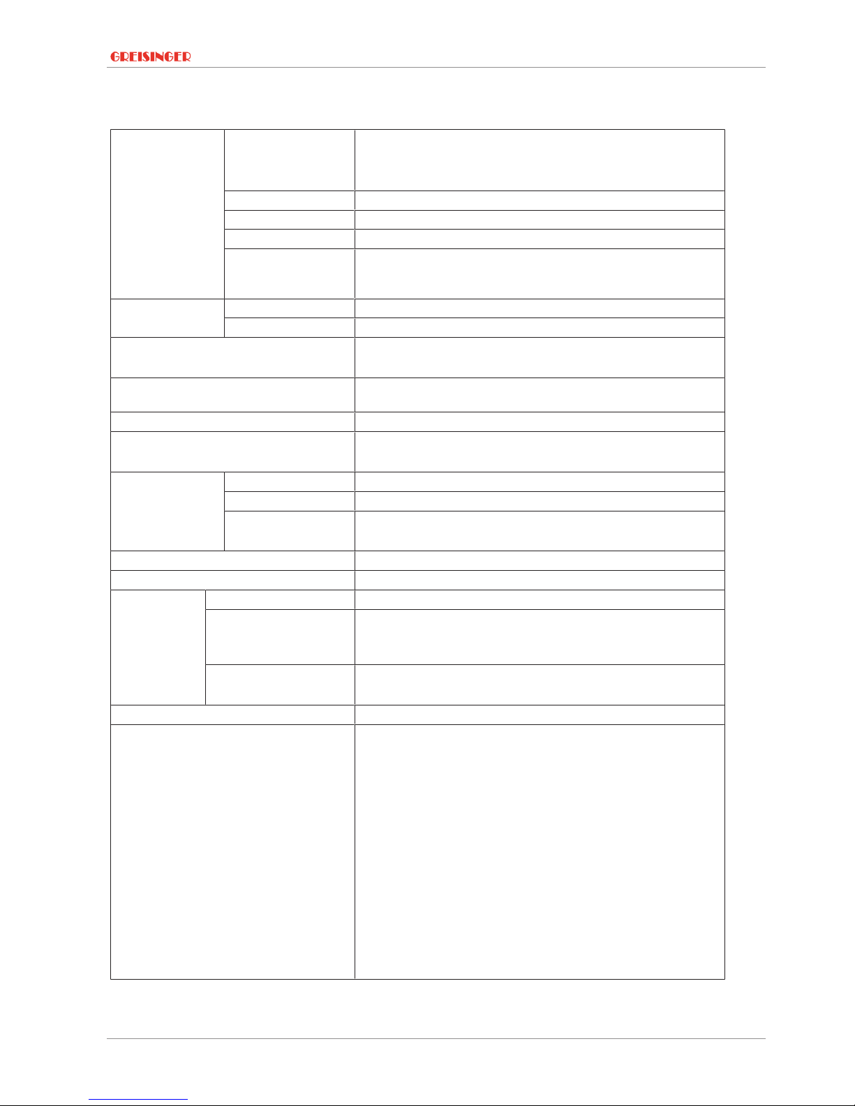
10 Technical data
Measuring range Conductivity 0 .. 2000 S/cm
0.00 .. 20.00 mS/cm
0.0 .. 100.0 mS/cm
Specific resistance Salinity 0.0 .. 50.0 g/kg
TDS 0 .. 2000 mg/l
Temperature -5.0 .. +105.0 °C (23.0 .. +221.0 °F) – the conductivity measur-
ing cells can be exposed temporarily to temperatures of up to
100 °C and permanently to temperatures of up to 80 °C.
Accuracy Conductivity ± 0.5 % of measured value ± 0.5 % FS
Temperature ± 0.3 °C
Measuring cycle approx. 10 measurements per second
Updating of the display approx. 2 times per second
Display 3-line segment LCD, additional symbols, illuminated (ad-
justable white, permanent illumination)
Additional functions Min/Max/Hold
Compensation Offset and gradient correction - temperature,
Gradient correction - conductivity
Housing Break-proof ABS housing
Protection rating IP65 / IP67
Dimensions L*W*H
[mm] and weight
108 * 54 * 28 mm without measuring cell or kink protection
180 g, incl. battery and measuring cell
Operating conditions -20 to 50 °C; 0 to 95 % r.h. (temporarily 100 % r.h.)
Storage temperature -20 to 70 °C
Power supply 2*AA battery (included in the scope of delivery)
Current requirement/
battery life
approx. 2.2 mA, approx. 3.5 mA with lighting
Service life > 1000 hours with alkaline batteries (without back-
lighting)
Battery indicator 4-stage battery status indicator,
Replacement indicator for depleted batteries: "BAT"
Auto-power-OFF function The device switches off automatically if this is activated
Directives and standards The devices conform to the following Directives of the Council
for the harmonisation of legal regulations of the Member
States:
2014/30/EU EMC Directive
2011/65/EU RoHS
Applied harmonised standards:
EN 61326-1:2013 Emission limits: Class B
Immunity according to Table 2
Additional errors: < 1 % FS
EN 50581:2012
The device is intended for mobile use and/or stationary opera-
tion in the scope of the specified operating conditions without
further limitations.
Page 26

11 | Spare parts and accessories Handheld conductivity measuring device
26 / 28 B-H87.0.01.DB2-1.0
11 Spare parts and accessories
A selection of spare parts and accessories for this product is listed below.
Article
Number Name Description
610049 Mignon batteryAAMignon AA spare battery
601396 GKL 100 100 ml conductivity control solution with 1413 µS/cm
601398 GKL 101 250 ml conductivity control solution with 84 µS/cm
601400 GKL 102 100 ml conductivity control solution with 50 mS/cm
603499 GWZ-01 Flow-through vessel (for measuring cells with Ø 12 mm
and Ø 6 mm hose connection)
700040 HD-22-3 Freely positionable, flexible laboratory electrode holding
arm for probes with Ø 12 mm
610049 GB AA AA battery
611373 ST-G1000 Device protection bag with 1 round cut-out
A complete list of all accessories and spare parts is available in our product catalogue
or on our home page. We can also provide further information by phone.
Contact
Internet: www.greisinger.de
Tel: +49 94029383-52
Page 27

Handheld conductivity measuring device Service | 12
B-H87.0.01.DB2-1.0 27 / 28
12 Service
12.1 Manufacturer
If you have any questions, please do not hesitate to contact us:
Contact
GHM Messtechnik GmbH
GHM GROUP - Greisinger
Hans-Sachs-Str. 26
93128 Regenstauf | GERMANY
Phone: +49 94029383-52
info@greisinger.de | www.greisinger.de
WEEE reg. no. DE 93889386
12.2 Repairs
Defective products are repaired professionally and quickly in our service centre.
Open hours and contact
Monday to Thursday from 8:00 to 16:00
Friday from 8:00 to 13:00
GHM Messtechnik GmbH
Hans-Sachs-Str.26
Service Centre
93128 Regenstauf | GERMANY
Phone: +49 94029383-39
Fax: +49 94029383-33
service@greisinger.de
NOTE
Fill in the return form available from the information base online at www.ghm-group.de
and sent it in with the product.
Page 28

12 | Service Handheld conductivity measuring device
28 / 28 B-H87.0.01.DB2-1.0
12.3 Sales subsidiaries
Austria
GHM Messtechnik GmbH
Office Austria
Breitenseer Str. 76/1/36
1140 Vienna | AUSTRIA
Phone +43 660 7335603
a.froestl@ghm-messtechnik.de
Brazil & Latin America
GHM Messtechnik do Brasil Ltda
Av. José de Souza Campos, 1073, cj 06
Campinas, SP
13025 320 | BRAZIL
Phone +55 19 3304 3408
Info@grupoghm.com.br
Czech Republic / Slovakia
GHM Greisinger s.r.o.
Ovci hajek 2 / 2153
158 00 Prague 5
Nove Butovice | CZECH REPUBLIC
Phone +420 251 613828
Fax +420 251 612607
info@greisinger.cz | www.greisinger.cz
Denmark
GHM Maaleteknik ApS
Maarslet Byvej 2
8320 Maarslet | DENMARK
Phone +45 646492- 00
Fax +45 646492- 01
info@ghm.dk | www.ghm.dk
France
GHM GROUP France SAS
Parc des Pivolles
9 Rue de Catalogne
69150 Décines-Charpieu (Lyon) | FRANCE
Phone +33 4 72 37 45 30
a.jouanilou@ghm-group.fr
India
GHM Messtechnik India Pvt Ltd.
209 | Udyog Bhavan | Sonowala Road
Gregaon ( E ) | Mumbai - 400 063
INDIA
Phone +91 22 40236235
info@ghmgroup.in | www.ghmgroup.in
Italy for Greisinger & Delta OHM
GHM GROUP – Delta OHM
Via Marconi 5
35030 Caselle di Selvazzano
Padova (PD) | ITALY
Phone +39 049 8977150
a.casati@ghm-messtechnik.de
Italy for Honsberg, Martens, Val.co
GHM GROUP – Val.co
Via Rovereto 9/11
20014 S. Ilario di Nerviano
Milano (MI) | ITALY
Phone +39 0331 53 59 20
alessandro.perego@valco.it
Netherlands
GHM Meettechniek BV
Zeeltweg 30
3755 KA Eemnes | NETHERLANDS
Phone +31 35 53805-40
Fax +31 35 53805-41
info@ghm-nl.com | www.ghm-nl.com
South Africa
GHM Messtechnik SA (Pty) Ltd
16 Olivier Street
Verwoerdpark, Alberton 1453
SOUTH AFRICA
Phone +27 74 4590040
j.grobler@ghm-sa.co.za
 Loading...