

Page 1

T20.0.34.6C-04 page 1 of 4
Operating Manual
EASYBUS Temperature Sensor Module
EBT – 2R, EBT – 2RE as of V2.8
Specification:
Display range: EBT-2R: -25.0 ... 70.0 °C or -13.0 ... 158.0 °F
EBT-2RE: -50.0 ... 150.0 °C or -58.0 ... 302.0 °F
Accuracy:
Sensors: EBT-2R: internal Pt1000 sensor
Min-/max-value memory: Min and max measured values are stored
(at nominal temperature) ±0.4% of measured value ±0.3°C
EBT-2RE: external Pt1000 sensor, connected via screw-type terminal
Output signal: EASY
Connection: 2-wire EASY
Busload: 1.5 EASY
Adjusting: via interface or keypress (at option VO) by input of offset and scale value
Display: (optional) approx. 10 mm high, 4-digit LCD-display
Ambient conditions for electronics:
Nominal temperature: 25 °C
Operating temperature: -25 to 70 °C
Relative humidity: 0 to 95 % RH (non-condensing)
Storage temperature: -25 to 70 °C
Housing: ABS
Dimensions: 70 x 70 x 26 mm
Mounting: With holes for wall mounting (in housing - accessible after cover has been removed).
Mounting distance: 60mm, max. shaft diameter of mounting screws is 4 mm.
Electrical connection: 2-pin screw-type terminal, max. wire cross section: 1.5 mm²
EMC: The
device corresponds to the essential protection ratings established in the Regulations of the Council for the
Approximation of Legislation for the member countries regarding electromagnetic compatibility (2004/108/EG).
In accordance with
When connecting long leads adequate measures against voltage surges have to be taken.
BUS-protocol
BUS, polarity free
BUS-devices
EN61326 +A1 +A2 (appendix A, class B), additional errors: < 1% FS.
Disposal instructions:
The device must not be disposed in the regular domestic waste.
Send the device directly to us (sufficiently stamped), if it should be disposed. We will dispose the device appropriate and
environmentally sound.
GREISINGER electronic GmbH
D - 93128 Regenstauf, Hans-Sachs-Straße 26
Tel.: 0049 9402 / 9383-0, Fax: 0049 9402 / 9383-33, eMail: info@greisinger.de
Page 2
T20.0.34.6C-04 page 2 of 4
Safety instructions:
This device has been designed and tested in accordance with the safety regulations for electronic devices.
However, its trouble-free operation and reliability cannot be guaranteed unless the standard safety measures and special
safety advises given in this manual will be adhered to when using the device.
1. Trouble-free operation and reliability of the device can only be guaranteed if the device is not subjected to any other
climatic conditions than those stated under "Specification". If the device is transported from a cold to a warm
environment condensation may cause in a failure of the function. In such a case make sure the device temperature
has adjusted to the ambient temperature before trying a new start-up.
2. General instructions and safety regulations for electric, light and heavy current plants, including domestic safety
regulations (e.g. VDE), have to be observed.
3. If device is to be connected to other devices (e.g. via PC) the circuitry has to be designed most carefully. Internal
connection in third party devices (e.g. connection GND and earth) may result in not-permissible voltages impairing or
destroying the device or another device connected.
4. If there is a risk whatsoever involved in running it, the device has to be switched off immediately and to be marked
accordingly to avoid re-starting.
Operator safety may be a risk if:
- there is visible damage to the device
- the device is not working as specified
- the device has been stored under unsuitable conditions for a longer time.
In case of doubt, please return device to manufacturer for repair or maintenance.
5. Warning:
Do not use this product as safety or emergency stop devices, or in any other application where failure of the product
could result in personal injury or material damage.
Failure to comply with these instructions could result in death or serious injury and material damage.
Assignment:
2-wire connection EASYBUS, no polarity, at terminals 1 and 2
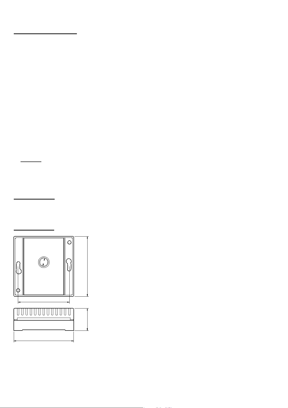
Dimensions:
Ø
9.0mm
70.0mm
60.0mm
26.0mm
70.0mm
Page 3

T20.0.34.6C-04 page 3 of 4
Display functions (only available for devices with option -VO)
Currently measured values
During normal operation the display will show the temperature in [°C] or [°F].
Min/Max Value Memory
watch Min values (Lo): press ‘down‘(middle key) shortly once display changes between ‘Lo‘ and Min values
watch Max values (Hi): press ‘up‘(right key) shortly once display changes between ‘Hi‘ and Max values
restore current values: press ‘down‘ or ’up’ once again current values are displayed
clear Min-values: press ‘down’ for 2 seconds Min values are cleared. The display shows shortly ‘CLr‘.
clear Max-values: press ‘up’ for 2 seconds Max values are cleared. The display shows shortly ‘CLr‘.
After 10 seconds the currently measured values will be displayed again.
Error and system messages
Display Description Possible fault cause Remedy
Err.1
Err.2
Err.7
Err.9
Er.11
8.8.8.8
measuring range exceeded Temperature is to large Check temperature
Measuring value below
measuring range
System fault Error in device
Sensor error Sensor or cable defective Check sensor, cable and connections
Calculation not possible
Segment test
Temperature is to low Check temperature
Disconnect from supply and reconnect. If error
remains: return to manufacturer
Calculation variable missing
or invalid
The transducer performs a display test for 2 seconds after power up. After
that it will change to the display of the measuring.
Check temperature
Configuration of the device
The configuration of the device is done by means of the PC-software EbxKonfig or EASYBUS-Konfigurator.
The following parameters can be changed:
- Display unit of temperature measuring
- Adjusting of temperature display (offset and scale correction)
- Setting of the alarm function
The adjusting by means of offset and scale is intended to be used to compensate errors of the measurings.
It is recommended to keep the scale correction deactivated (“oFF”). The display value is given by following formula:
Display = measured value - offset
With a scale correction (just for calibration laboratories, etc) the formula changes:
Display = (measured value - offset) * ( 1 + scale adjustment/100)
Page 4

T20.0.34.6C-04 page 4 of 4
Configuration at the device (only available for devices with option -VO)
Attention: If EASYBUS sensor modules are operated by a data acquisition software, there
can be problems if the configuration is changed during a running acquisition.
Therefore it is recommended not to change configuration values during a
running recording and furthermore to protect it against manipulation by
unauthorised persons. If the jumper connecting the contacts shown in the
figure is removed, the configuration is not accessible, the settings are
protected. Never connect the other contacts!
To configure the parameters at the device proceed like follows:
1. Press the key 1 (SET) for more than 4 sec’s until 'Unit' appears in the display.
I.) 'Unit': Temperature unit
Enter the desired Temperature unit. All referring settings and displays are done in this unit.
2. Choose the desired unit by pressing 2 (down) or 3 (up) key. Choice between °C and °F (ex works: °C)
3. Enter by pressing key 1 (SET), select next parameter by pressing key 1 again: 'OFFS' appears in the display.
II.) 'OFFS': Offset of temperature measuring (correction of measuring deviations):
The offset of the measuring will be shifted by this value, the input is in °C. Calculation: see above.
4. Choose the desired value by pressing 2 (down) or 3 (up) key.
Max. input range: -5.0...5.0 °C / -9.0...9.0 °F or 'oFF': offset is deactivated (oFF=0.0, ex works)
5. Enter by pressing key 1 (SET), select next parameter: 'SCAL' appears in the display.
III.) 'SCAL': Scale of temperature measuring (correction of measuring deviations):
The scale of the measuring is changed by this value. Calculation: see above.
6. Choose the desired value by pressing 2 (down) or 3 (up) key.
Max. input range: -2.00...2.00 or 'oFF': scale is deactivated (oFF=0.00, ex works)
7. Enter by pressing key 1 (SET), select next parameter: 'AL.Lo' appears in the display.
IV.) 'AL.Lo': min. alarm-point for temperature-measuring:
Enter the desired min. alarm-point. At resp. below the value that has been set an alarm message will occur.
8. Choose the desired value by pressing 2 (down) or 3 (up) key. Input range: -25.0 to AL.Hi °C
9. Enter by pressing key 1 (SET), select next parameter: 'AL.Hi' appears in the display.
V.) 'AL.Hi': max. alarm-point for temperature-measuring:
Enter the desired min. alarm-point. At resp. above the value that has been set an alarm message will occur.
10. Choose the desired value by pressing 2 (down) or 3 (up) key. Input range: AL.Lo...50.0 °C
11. Enter by pressing key 1 (SET), select next parameter: 'AL.dE' appears in the display.
VI.) 'AL.dE': alarm-delay for temperature-measuring:
The alarm will start, when the alarm condition exists for the entered delay time.
12. Choose the desired value by pressing 2 (down) or 3 (up) key. Max. input range: oFF; 0...9999 min.
Enter by pressing key 1 (set). After pressing 1 again, the instrument will restart, (display shows 8.8.8.8 segment test).
Notice: In case an alarm is active, the display will show alternating AL.Lo resp. AL.Hi and the measured value
1 2 3
Jumper
 Loading...