

Greisinger EB 3000 User guide

E35.0.01.6C-03 Manual for connection and operation of the EB 3000 page 1 of 19
Manual for connection and operation of
EASYBus-control, display and supervisory device
EB 3000
as of Version 1.7
GREISINGER electronic GmbH
D - 93128 Regenstauf, Hans-Sachs-Straße 26
Tel.: 09402 / 9383-0, Fax: 09402 / 9383-33, e-mail: info@greisinger.de

E35.0.01.6C-03 Manual for connection and operation of the EB 3000 page 2 of 19
I N D E X
1. SAFETY REGULATIONS .......................................................................................................................................... 3
2. INTRODUCTION ........................................................................................................................................................4
2.1. EASYBUS-terms and definitions......................................................................................................................... 4
3. DISPLAY ELEMENTS AND PUSHBUTTONS........................................................................................................ 5
4. ELECTRIC CONNECTION ....................................................................................................................................... 6
4.1. Terminal assignment................................................................................................................................................ 6
4.2. Connection data ....................................................................................................................................................... 6
4.3. Connection example ................................................................................................................................................7
4.3.1. Connection information:................................................................................................................................... 7
5. COMMISSIONING AND CONFIGURATION OF THE EB3000 .......................................................................... 8
5.1. Initial commissioning of the EB3000 ...................................................................................................................... 8
6. OPERATION OF THE EB3000.................................................................................................................................. 8
6.1. How to display the current measurement values...................................................................................................... 8
6.2. How to display or reset the min-/max-values .......................................................................................................... 9
6.3. Setting of switching points.......................................................................................................................................9
6.4. Setting of alarm limits.............................................................................................................................................. 9
7. ERROR CODES ......................................................................................................................................................... 11
8. SPECIFICATION....................................................................................................................................................... 14
9. DISPOSAL NOTES.................................................................................................................................................... 14
10. EB3000 - CONFIGURATION................................................................................................................................. 15
10.1. EASYBUS - Configurator ...................................................................................................................................15
10.1.1. Interface configuration..................................................................................................................................15
10.1.2. Perform EASYBUS system initialisation ..................................................................................................... 15
10.1.3. Read EASYBUS........................................................................................................................................... 15
10.2. EB3000 - Configuration....................................................................................................................................... 16
10.2.1. Tab: monitoring / display............................................................................................................................. 16
10.2.2. Tab: control outputs..................................................................................................................................... 18
10.2.3. Tab: alarm.................................................................................................................................................... 18
10.2.4. Tab: virtual channels.................................................................................................................................... 19
10.2.5. Tab: others ................................................................................................................................................... 19
E35.0.01.6C-03 Manual for connection and operation of the EB 3000 page 3 of 19
1. Safety regulations
This device was designed and tested considering the Safety regulations for electronic measuring devices.
Faultless operation and reliability in operation of the measuring device can only be assured if the General
Safety Measures and the devices specific safety regulation mentioned in this users manual are considered.
1. Faultless operation and reliability in operation of the measuring device can only be assured if the device
is used within the climatic conditions specified in the chapter “Specifications“.
2. Always disconnect the device from its supply before opening it. Take care that nobody can touch any of
the unit‘s contacts after installing the device.
3. Standard regulations for operation and safety for electrical, light and heavy current equipment have to be
observed, with particular attention paid to the national safety regulations (e.g. VDE 0100).
4. When connecting the device to other devices (e.g. the PC) the interconnection has to be designed most
thoroughly, as internal connections in third-party devices (e.g. connection of ground with protective earth)
may lead to undesired voltage potentials.
5. The device must be switched off and must be marked against using again, in case of obvious malfunctions of the device which are e.g.:
- visible damage
- no prescripted working of the device
- storing the device under inappropriate conditions for longer time
When not sure, the device should be sent to the manufacturer for repairing or servicing.
Attention: When running electric devices, parts of them will always be electrically live.
Unless the warnings are observed serious personal injuries or damage to property
may result. Skilled personnel only should be allowed to work with this device. For trouble-free and safe operation of the device please ensure professional transport, storage, installation and connection as well as proper operation and maintenance.
Skilled personnel
are persons familiar with installation, connection, commissioning and operation of the product and have professional qualification relating to their job.
For example:
• Training or instruction resp. qualifications to switch on or off, isolate, ground and mark electric circuits and
devices or systems.
• Training or instruction according to the state.
• First-aid training.
ATTENTION:
Do NOT use this product as safety or emergency stopping device, or in any other application where failure of the product could result in personal injury or material damage.
Failure to comply with these instructions could result in death or serious injury and material damage.

E35.0.01.6C-03 Manual for connection and operation of the EB 3000 page 4 of 19
2. Introduction
The EB3000 is an universal control, display and supervisory device for EASYBUS-sensor modules.
The EB3000 is equipped with 20 internal channels (channel-nr. 1..20), which can be allocated arbitrary to
different EASY
trary calculation functions.
Furthermore the EB3000 has 4 switching outputs and an alarm output.
The 22 channels can be allocated arbitrary to the 4 switching outputs to realise different type of control (2point-, 3-point-controller, stepping switch etc.).
Due to load arbitrary calculation functions it is possible to realise extensive display and control functions (as
BUS-measurement channels and 2 virtual channels (channel-nr. 21 and 22), to download arbi-
max
min
EB3000
Out1
Alarm
SET
1 234
Out2 Out3 Out4
°C
%RH
GREISINGER
electronic
averaging, Difference regulation etc. .
The device features 2 displays: a 4-digit 13mm high 7-segment display (main display) to indicate measure-
ment values or error codes and a 2-digit 7mm high 7-segment display (auxiliary display) for indication of the
free configurable channel description.
Additionally there are 4 LED´s for displaying the unit of the current measurement channel, 4 LED’s for displaying the actual state of the switching outputs and 3 LED’s which illuminates in case of alarm or in case of a
selected min-/max-value.
The device has 2 EASY
- EASY
- EASY
BUS-output: connection for the EASYBUS-sensor modules
BUS-input: permits via level converter (e.g. EBW1, EBW64, ...) communication with a superior
BUS-Interfaces:
computer (master).
The EB3000 cyclically enquires all the allocated measurement channels. The sequence for processing the
channels isn’t firm, because there is a dynamic request fitted to each channels slightest updating-rate (timeout). Measurement channels with fast turn of events are frequently requested as measurement channels with
slow turn of events.
The EB3000 checks the compliance of the required updating-rate. If the enquiry of a measurement channel,
within a specified time-interval, as a result of bus capacity overload (e.g. by frequent and time-consuming
enquiries of the master), is not possible, a ‚timeout‘-errormessage indicates on the display and alarm is activated. If not required, timeout-control can also be deactivated.
Before the EB3000 can be used, it has to be configured for the customer’s application
(see chapter 5).
2.1. EASYBUS-terms and definitions
Declaration of used terms and definitions:
EASY
BUS-sensor modules sensor module for connection on EASYBUS
(e.g. EASYLOG 40K, EASYLOG 24RFT, EASYLOG 40NS, EBHT)
EASY
BUS-measurement channel measurement channel of an EASYBUS-sensor module
The EASY
(e.g. EASY
ity and one channel for temperature measurement)
BUS-modules can feature one ore more measurement channels
LOG 24RFT and EBHT features 2 channels – one channel for humid-
E35.0.01.6C-03 Manual for connection and operation of the EB 3000 page 5 of 19
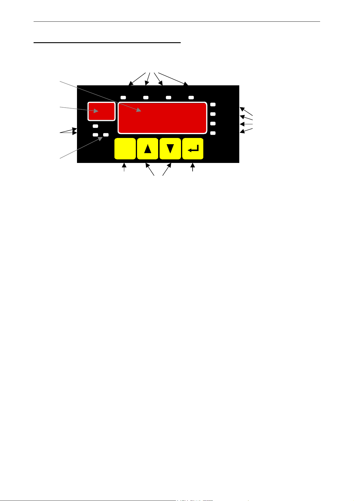
3. Display elements and pushbuttons
8
4
Out1
5
6
max
min
7
Alarm
EB3000
SET
1 234
Out2 Out3 Out4
°C
%RH
GREISINGER
electronic
1 2 3
Device front view
1Key 1: change-over to setting mode (in combination with key 2 or 3)
switching between indication of current value, min-value and max-value
2Key 2: change-over to next measurement channel
Key 3: change-over to further measurement channel
increasing / decreasing of the last setting
setting mode selection
9
3Key 4: interruption / recognition of the last setting
acknowledgement of an error message
4 Main display: indication of current measurement value resp. min.-/max-value
5 Auxiliary display: indication of current measurement channel
6 Min-/max-values: illuminates in case of a selected min-/max-value
7 Alarm display: illuminates in case of an alarm
8 LED‘s Out1...4: indicates the actual state of the switching outputs
9 LED‘s 1...4: displays the unit of the current measurement channel
E35.0.01.6C-03 Manual for connection and operation of the EB 3000 page 6 of 19
4. Electric connection
Electric connection and commissioning of the device must be carried out by trained and skilled personnel.
Wrong connection may lead to the destruction of the device, in which case we cannot assume any
warranty.
Make it a rule to always mount screw-type/plug-in terminals while they are still loose and connect only later. If terminals
are mounted after connection there is a risk that soldering eyes may come loose. Please use suitable screw-driver and
do not tighten screws by force.
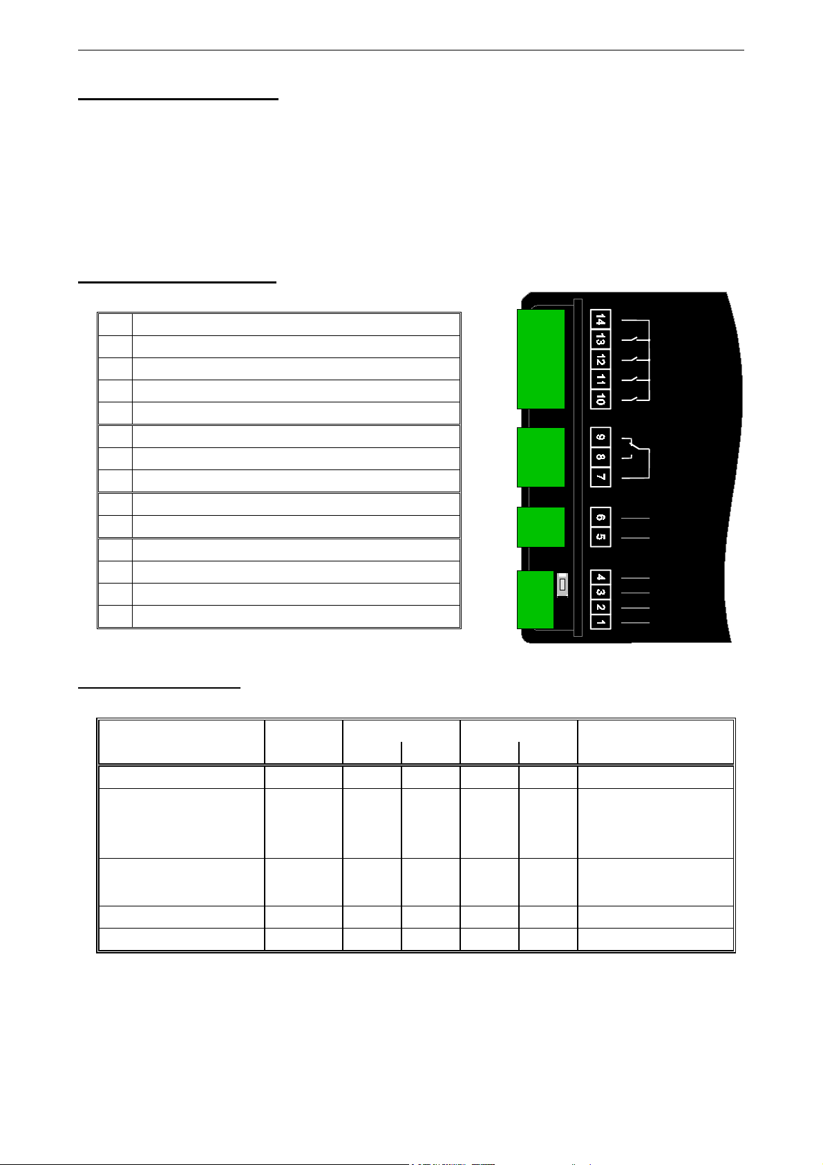
4.1. Terminal assignment
14
Switching output 1..4 (common connector)
13
Switching output 1 (normally open)
12
Switching output 2 (normally open)
11
Switching output 3 (normally open)
10
Switching output 4 (normally open)
9
Alarm output (normally closed)
8
Alarm output (normally open)
7
Alarm output (common connector)
6
Supply voltage: 230V
5
Supply voltage: 230V
4
EASYBUS-Input (to PC/Host)
3
EASYBUS-Input (to PC/Host)
2
EASYBUS-Output (to EASYBUS-sensor modules)
1
EASYBUS-Output (to EASYBUS-sensor modules)
AC
AC
Rel 1
Rel 2
Rel 3
Rel 4
Alarm
230 V
AC
EB
in EB
out
4.2. Connection data
between
terminal
Supply voltage 5 and 6 207 VAC 243 VAC 250 VAC
14 and 13,
Switching outputs
14 and 12,
14 and 11,
14 and 10
Alarm output 7 and 8, 9
EASYBUS-output 1 and 2 36 VDC
EASYBUS-input 3 and 4 36 VDC
These limits must not be exceeded (not even for a short time) !
typical limitations
min. max. min. max.
250
VAC
5A
(ohmic load)
250
VAC
5A
(ohmic load)
notes
or as specified on rating plate
Use RC circuit elements or
varistors for inductive loads
Use RC circuit elements or
varistors for inductive loads
 Loading...