


E40.0.01.6C-02
E
9
m
a
i
O
i
from Version V1.5
Operating Manual
Data logger for
EASY
humidity
temperature
air pressure
L
G
80 CL
GR
D - 931
phone.: +4
ISINGER
28 Regenstauf, Hans-Sachs-Str
9402 / 9383-0, fax: +49 9402 / 9383-33, eMail: info@gre
electronic G
bH
ße 26
singer.de

E40.0.01.6C-02 Operating Manual EASY
LOG
80 CL Page 2 of 12
Content
1. General description .................................................................................................... 2
2. Required accessory ................................................................................................... 2
3. Safety advice ............................................................................................................. 3
4. Notes on the logger’s delivery status ......................................................................... 3
5. EASYBus connector .................................................................................................. 4
6. Display and control elemtents .................................................................................... 4
6.1 Display .................................................................................................................... 4
6.2 Function of the buttons (brief description) ............................................................... 4
7. Operation ................................................................................................................... 5
7.1 Operating possibilities at the device - display selection .......................................... 5
7.2 Operating possibilities at the device - logger operation ........................................... 6
7.3 Operating possibilities via software GSOFT 40K .................................................... 7
7.4 Operating possibilities via software EBxKonfig or EASYBus-configurator .............. 7
8. Battery life time and recording period ........................................................................ 7
9. Operating displays ..................................................................................................... 8
9.1 Measured value display .......................................................................................... 8
9.2 Logger status messages ......................................................................................... 8
9.3 System messages ................................................................................................... 9
9.4 Alarm and error messages ...................................................................................... 9
10. Specifications ........................................................................................................... 10
11. Disposal ................................................................................................................... 11
12. Frequently asked questions [FAQ] ........................................................................... 12
1. General description
The logger EASY
relative humidity, temperature and air pressure can be displayed, but also wet-bulb temperature, dew-point temperature, enthalpy and the moisture content of the air.
The combination of low power consumption with high battery capacity ensure a long recording time.
The last 250.000 measuring values of each variable (that means 1.000.000 values all in all)
are stores in the memory.
The LCD-display informs about 2 different variables at the same time (i.e. temperature and
humidity) or about the operating status of the logger.
LOG
80 CL is designed for long term monitoring of climate data. Not only
2. Required accessory
The EASY
Therefore the following accessories are required:
Level converter
- RS232 <> EASYBus (i.e. EBW 1, EBW 64, EBW 240)
or
- USB <> EASYBus (i.e. EBW 3)
LOG
80 CL is configurated, started and read-out via the EASYBus-interface.
LOG
Connecting cable: level converter to EASY
GSOFT 40K (version >7.14):
Windows software to start the logger and read out the logger-data
EASYBus-Configurator (version >2.0) or EBxKonfig (version >3.9):
for the configuration of the extended settings

E40.0.01.6C-02 Operating Manual EASY
LOG
80 CL Page 3 of 12
3. Safety advice
This device has been designed, assembled and tested in accordance with the safety regulations for electronic measuring device. However, its trouble-free operation and reliability
cannot be guaranteed unless the standard safety measures and special safety advices
regarding the device will be adhered to when using the device.
1. Trouble-free operation and reliability of the device can only be guaranteed if the
device is not subjected to any other climatic conditions than those stated under
”Specification”.
To protect the battery, the maximum permissible storage and transport
temperature of the device is 70 °C
2. Standard regulations for operation and safety for electrical, light and heavy current
equipment have to be observed, with particular attention having to be paid to
national safety regulations.
3. When connecting the logger to other devices (e.g. PC) the interconnection has to
be designed most thoroughly as internal connections in third-party devices (e.g.
connection GND with protective earth) may lead to undesired voltage potentials.
4. If there is any risk whatsoever involved in running it, the device has to be switched
off immediately and to be marked accordingly to avoid re-starting.
Operator safety may be at risk if:
• there is visible damage done to the device
• the device is not working as specified
• the device has been stored under unsuitable conditions for a longer time.
In case of doubt, please return device to manufacturer for repair and maintenance.
5. Warning:
Do not use these product as safety or emergency stop devices, or in any other
application where failure of the product could result in personal injury or material
damage.
Failure to comply with these instructions could result in death or serious
injury and material damage.
4. Notes on the logger’s delivery status
The delivered logger is in a “sleep mode”, that means nothing is displayed and the
power consumption is at its minimum. When there is a communication with the software
for the first time, the EASY
device is ready for operation.
Note: That sleep mode (nothing is displayed) cannot be restored again.
“Stop“ or “Halt“ are similar to the sleep mode. Both of that operation
modes ensure minimum consumption.
Note: Logger start over keypad:
before logger start over keypad, logger time must be adjust with
GSOFT 40K.
LOG
leaves the sleep mode and ›Stop‹ is displayed. Then the

E40.0.01.6C-02
o
o
y
p
o
a
k
r
n
o
u
a
b
W
Y
c
L
T
T
Operating Manual EASY
LOG
80 CL
Page 4 of 12
5. EASYBus connect
6. Display and contr
6.1 Display
Main display
r
EAS
not
l elements
Assignment of
(view on
panel jack
pins)
Bus connection
onnected
Secondary displa
Arrows for unit dis
(for calculated vari
Display element f
Logg: indicates th
recording
BAT: signals wea
(see chapte
AL: signals an a
minimum o
SL: signals an a
correction f
pressure
6.2 Function of the b
SET
SET
1
(button 1)
• switch displ
• call menu
lay
ables)
r max / min
t logger is
battery
9).
larm state at
e channel
ctive sea-level
r the air
ttons (brief description)
g
³
k
/
m
/
J
g
k
MAX
DIF
MIN
BAT
SET
12
g
b
k
/
d
w
g
T
%
°C
°C
hPa
ogg
SLAL
3
Arrow key UP
2
• call / delete
Arrow key DO
3
• call / delete
(
utton 2)
max-value
N
(button 3)
min-value

E40.0.01.6C-02 Operating Manual EASY
LOG
80 CL Page 5 of 12
7. Operation
7.1 Operating possibilities at the device - display selection
Function Procedure
Switch display
Display max-value
Delete max-value
Display min-value
Push button shortly
SET
1
The measuring channel is switched
Note: The measuring channel is automatically switched
every 4 sec.
Push button shortly
2
The max-values of the measuring channel are displayed for 4
seconds.
(The max-value display function is signalled by the display
element “MAX”).
Note: You can immediately switch to the next measuring
channel pushing the button again.
Push button for about 5 seconds.
2
“CLr” is displayed and the max-values of all measuring
channels are deleted.
Push button shortly
3
The min-values of the measuring channel are displayed for 4
seconds.
(The min-value display function is signalled by the display
element “MIN“).
Note: You can immediately switch to the next measuring
channel pushing the button again.
Delete min-value
Push button for about 5 seconds.
“CLr” is displayed and the min-values of all measuring
3
channels are deleted.

E40.0.01.6C-02 Operating Manual EASY
LOG
80 CL Page 6 of 12
7.2 Operating possibilities at the device - logger operation
Function Procedure
Display and adjust
cycle time
Start recording
Push button and at the same time.
SET
1 2
The main display shows “CYCL”. The secondary display
shows the currently adjusted cycle time [in sec.].
If the logger is currently not recording, the desired cycle time
[4 sec to 5h (18000 sec)] can be adjusted via the buttons
and .
2 3
Press button again to confirm your adjustments and to
SET
1
leave the menu.
Note: If no key is pressed for more than 2 min, the menu is
quit without saving.
Push button for about 5 seconds.
SET
1
The main display shows “run”.
The secondary display shows “no”.
To start recording select “YES” with the arrow keys
(button or ) and verify with .
2 3
SET
1
Note: If no key is pressed for more than 2 min, the menu is
quit without saving.
Push button for about 5 seconds.
SET
1
The main display shows “HoLd”.
The secondary display shows “no”.
To stop recording select “YES” with the arrow key
Stop recording
(button or ) and verify with .
If no key is pressed for more than 2 min, the menu is
Note:
2 3
quit without saving.
Notice:
If you have activated one of the following options
• “logger stop via buttons disabled”
• “do not stop active logger”
at the configuration of the logger the menu to
stop the recording cannot be called.
SET
1

E40.0.01.6C-02 Operating Manual EASY
LOG
80 CL Page 7 of 12
7.3 Operating possibilities via software GSOFT 40K
You can easily operate the logger via the software GSOFT 40K (> V7.14). This software
provides a variety of functions to operate the logger. For example:
• start and stop the logger
• read out the logger data; illustrate them graphically and save them
• adjust the alarm boundaries and alarm delay *1
• activate the sea-level correction and enter the actual sea level *1
Description: The measured barometric air pressure can be converted to the air
pressure at sea level if the actual height above sea level is entered.
• activate the function: “logger stop via buttons disabled“
*1 Please note: The alarm settings and the sea-level correction can be only
changed if the logger is stopped (= logger without logger data).
7.4 Operating possibilities via software EBxKonfig or EASYBusconfigurator
The software EBxKonfig (> V2.0) or EASYBus-configurator (> V3.9) is needed to
change the configuration settings.
With that software the following adjustment are additionally possible.
• Selection of the unit of the calculated variables*2
• Offset and slope adjustment for each measured variable *2
• Activation of the function: “do not stop active logger”
*2 Please note: This can be only changed if the logger is stopped (=logger without
logger data)
8. Battery life time and recording period
Measuring cycle: 4 sec 3 min 15 min 5 h
Recording period: 11.5 days 521 days 7.1 years 142 years
Battery life time: -- -- ca. 5 years --
Please note: Short measuring cycles seriously reduce the battery life time!
In this case you should consider not unplugging the EASYBus-
interface.
Then the logger is supplied via the interface.
The internal battery is spared.

E40.0.01.6C-02 Operating Manual EASY
9. Operating displays
LOG
80 CL Page 8 of 12
The EASY
LOG
provides two LCD-displays: 7 mm (main display) and
5.8 mm (secondary display).
9.1 Measured value display
The LCD mainly displays the measured values:
a)
%
°C
AL Logg
b)
°C
hPa
SL Logg
MEASURED VALUE DISPLAY
Alternating display of the following measuring channels:
a) main display: humidity [ % ]
sec. display: temperature [ °C ]
b) main display: selected calculated variable with the
corresponding unit arrow (here: Td)
sec. display: air pressure [ hPa ]
The particular measuring channels are displayed for about 4 sec.
and then are automatically switched to the next ones.
• The arrow “Logg“ signals that the logger is recording.
• The arrow “AL“ signals an alarm state at minimum one channel.
• The arrow “SL“ signals an active sea-level correction .
9.2 Logger status messages
At stand-alone-operation (= no EASYBus connected) logger status messages are displayed.
STOP:
The EASY
The logger memory is empty.
Note: At this state the power consumption is at its
HOLD:
The EASY
but the logger memory contains data.
The number of the saved recording sets is shown at the
secondary display.
START DELAY:
The logger is activated, but no data is recorded yet.
As soon as the start delay is run out the logger begins with the
recording according to the programmed starting condition.
START ALARM:
The logger is activated, but no data is recorded yet.
The logger begins with the recording as soon as the measured
values are within the selected min- and max-alarm boundaries.
LOG
recording has been ›stopped‹.
minimum.
LOG
recording has been ›halted‹. No data is stored,

E40.0.01.6C-02 Operating Manual EASY
r
9.3 System messages
...
BATTERY:
LOG
80 CL Page 9 of 12
%
°C
The EASY
LOG
battery is almost spent and needs to be replaced.
The data recording is still active.
• permanent display BAT:
The battery is spent and the recording has been automatically
stopped (even if at EASYBus-operation).
It is still partly possible to read the measured values and to
• display of the BAT-arrow left hand down:
read-out the saved logger data.
=> Please return the logger to the manufacturer.
ERROR
The EASY
7
:
LOG
has detected a system error.
• remedy: Reset the error via GSOFT 40K.
If the error message is displayed furthermore please
send the logger to the manufacturer for repair.
9.4 Alarm and error messages
The following messages correspond to a particular measuring channel and are displayed accordingly.
ALARM LOW:
The measured value is below the selected min-alarm limit.
This and the current value is displayed alternately.
ALARM HIGH:
The measured value is above the selected max-alarm limit.
This and the current value is displayed alternately.
ERROR
The measuring range of this channel is exceeded.
ERROR
The measuring range of this channel is under-run.
ERROR
The sensor for this channel provides invalid values.
ERROR
The variable could not be calculated, because the measuring
1
2
9
11
:
:
:
:
range has been exceeded or a measured value, that is needed fo
the calculation, is not available or faulty.
Note: A description of the possible reasons for that error messages is in
chapter 12 (FAQ).

E40.0.01.6C-02 Operating Manual EASY
10. Specifications
%
°C
MAX
°C
DIF
MIN
SET
123
hPa
Measuring range:
Temperature -25.0 … +60.0 °C
LOG
80 CL Page 10 of 12
Humidity
0.0 … 100.0 %RH
(recommended range : 10 … 90 %RH)
Air pressure 300.0 … 1100.0 hPa (mbar)
Additional selectable
variables
Wet-bulb temperature -27.0 … +60.0 °C
Dew point temperature -40.0 … +60.0 °C
Enthalpy -25.0 … 999.9 kJ/kg
Moisture content of the air
0.0 … 640.0 g/kg
Resolution 0.1 °C / 0.1 %RH / 0.1 hPa
Accuracy (± 1 digit):
Temperature ±0.3 °C ±0.017 * (T – 25 °C)
Humidity ±2 %RH (at range 10 … 90 %RH)
Air pressure ±1.0 mbar (typ.), ±2.5 mbar (max.)
Display
two 4½-digit LCD-displays
(about 7 and 5.8 mm high)
Interface EASYBus
Busload equals to 2 EASYBus-elements
depending on the chosen measuring cycle
Battery life time
about 5 years
(at 15 minutes and nominal temperature).
Measured value memory 250.000 measuring values of each variable
Measuring cycle 4 seconds to 5 hours (18000 seconds)
Memory type:
›cyclic logger‹ • recording can be activated by start/stop function
(i.e. key-press, boundaries).
• 64 independent recording sets are possible.
›ring logger‹ The logger records continuously;
as soon as the whole memory is used the old data
of the beginning are overwritten.

E40.0.01.6C-02 Operating Manual EASY
©
%
°C
MAX
DIF
MIN
SET
123
°C
hPa
Recording period depending on the chosen measuring cycle
i. e. 521 days at 3 min measuring cycle
7.1 years at 15 min measuring cycle
Alarm function alarm points selectable within the measuring range
and alarm delay adjustable from 0 to 500 min
Nominal temperature 25 °C
Operating temperature -25.0 … +60.0 °C
Storage temperature -30.0 … +70.0 °C
Housing
LOG
80 CL Page 11 of 12
Dimensions
Design
Sensor tube about Ø 15 mm, made of polyamide
Protection head
11. Disposal
This device must not be disposed as “residual waste”. To dispose this device,
please send it directly to us (adequately stamped). We will dispose it appropriately and environmentally friendly.
48.5 × 48.5 × 35.5 mm (L × W × D)
without sensor and plug
ABS housing, transparent screen made of polycarbonate, splash-proof according to IP65
removable twist plastic head made of
polycarbonate
Copyright 2008 GREISINGER electronic GmbH. All Rights Reserved.
No part of this documentation may without previous written permission of the
company GREISINGER electronic GmbH stored in some form, reproduced,
processed, duplicated or spread become.
E40.0.01.6C-02 Operating Manual EASY
LOG
80 CL Page 12 of 12
12. Frequently asked questions [FAQ]
Problem: The logger cannot be stopped via keys.
Possible reason: “Logger stop via buttons disabled” has been activated at the configu-
ration of the logger.
Remedy: Deactivate this function by means of GSOFT 40K (at tab „settings“).
Problem: The logger cannot be stopped both via keys and GSOFT 40K.
Possible reason: “Do not stop active logger” has been activated at the configuration of
the logger.
Remedy: Deactivate this function by means of EASYBus-configurator or
EbxKonfig.
Problem: The alarm settings or the sea-level correction cannot be
changed.
Possible reason: The logger has still saved data.
Remedy: Stop logger as recommended by the software (delete data).
Problem: The desired calculated variable cannot be changed.
Possible reason: The logger has still saved data.
Remedy: Stop logger as recommended by the software (delete data).
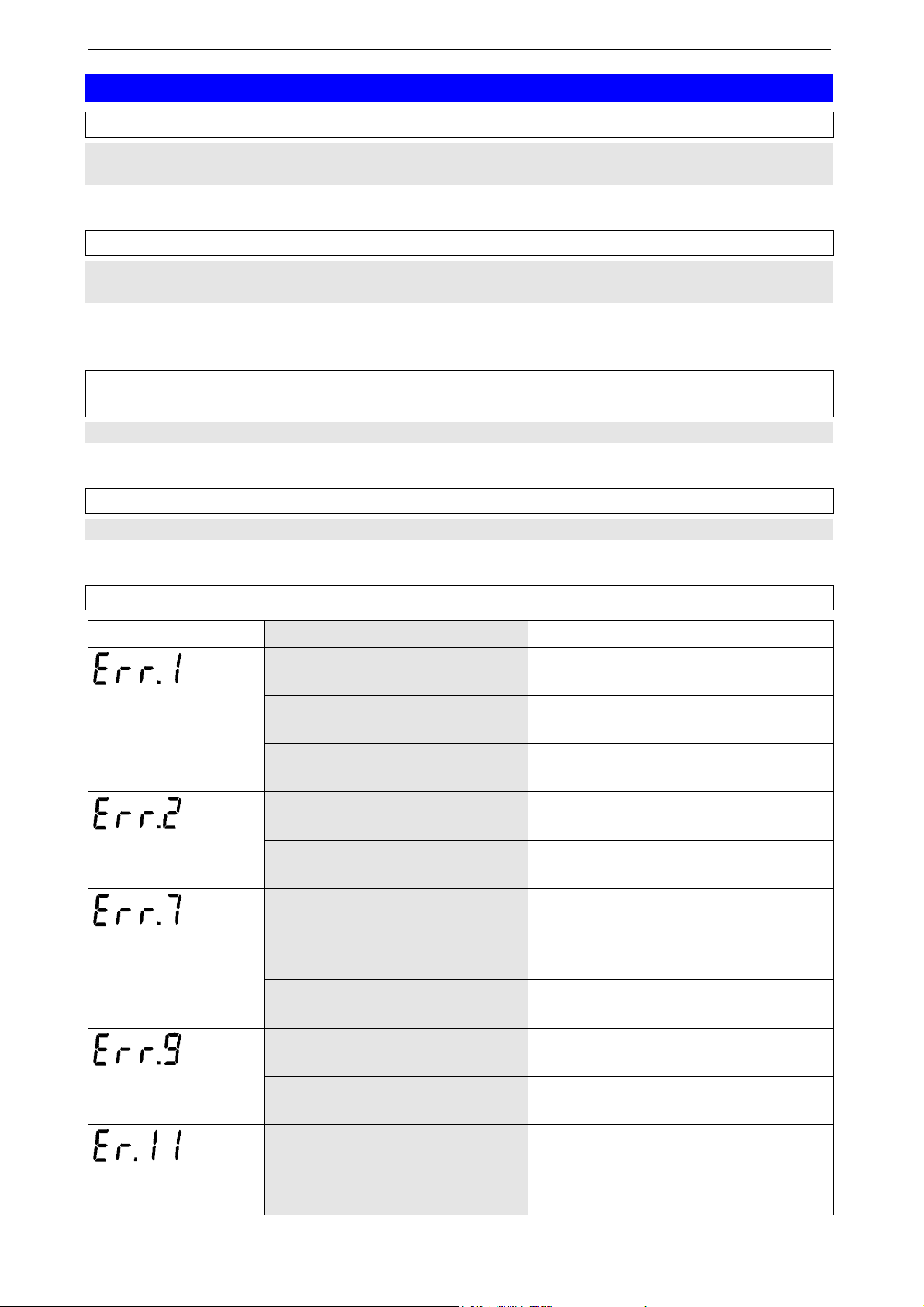
Problem: A error message is displayed.
Error message Possible reason procedure / remedy
measuring range
exceeded
Measuring range of the channel has been exceeded.
humidity: sensor bedewed Twist filter cap carefully off and let
Operate logger within its specifications.
sensor dry.
Sensor defective Send the logger to the manufac-
turer for repair.
measuring range
under-run
Measuring range of this channel is under-run.
Sensor defective Send the logger to the manufac-
Operate logger within its specifications.
turer for repair.
Recording error Reset the error via GSOFT 40K.
system error
If the error message is displayed
furthermore send the logger to the
manufacturer for repair.
sensor error
calculation error
System error Send the logger to the manufac-
turer for repair.
Humidity / temperature sensor
has moved out of its socket
Check the position of humidity /
temperature sensor.
Sensor defective Send the logger to the manufac-
turer for repair.
Error message at a variable
needed for the calculation
Remedy the reason for error at this
channel.
(humidity / temperature / pressure)
 Loading...