

Greifzug Tirak X 1020, Tirak X 1530, Tirak T 1020, Tirak X 3050, Tirak X 300 Operation And Installation Manual
...Page 1

tirak™
Electrically driven rope traction hoists for wire ropes for material transportation
Elektrisch angetriebene Seildurchlaufwinden für Drahtseile zur Materialbeförderung
Treuils électriques à défilement continu pour câbles métalliques pour le transport de matériaux
Elektrisch aangedreven kabeldoorlooplieren voor draadkabels voor het materiaaltransport
Model series / Typenreihe /
Série / Serie
T 1000
T 1020
Model series / Typenreihe /
Série / Serie
X 300
X 400
X 500
X 800
X 1020
X 1530
Model series / Typenreihe /
Série / Serie
X 3050
Original Operation and Installation Manual
Traduction du manuel d´installation et de
manutention original
Übersetzung der Original-Montage- und
Betriebsanleitung
Vertaling van de originele montage- en
bedieningshandleiding
English
Deutsch
Français
Nederlands
Page 2
tirak™
EN-DE-FR-NL–II G932.1 - 06/2010
DE
FR
NL
ENEN
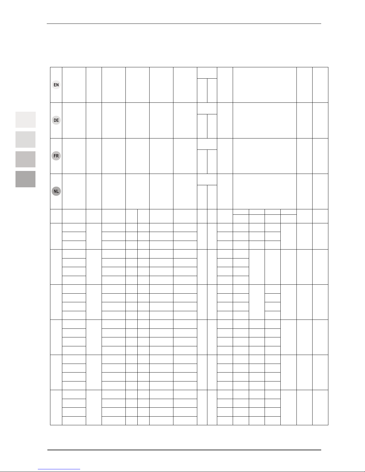
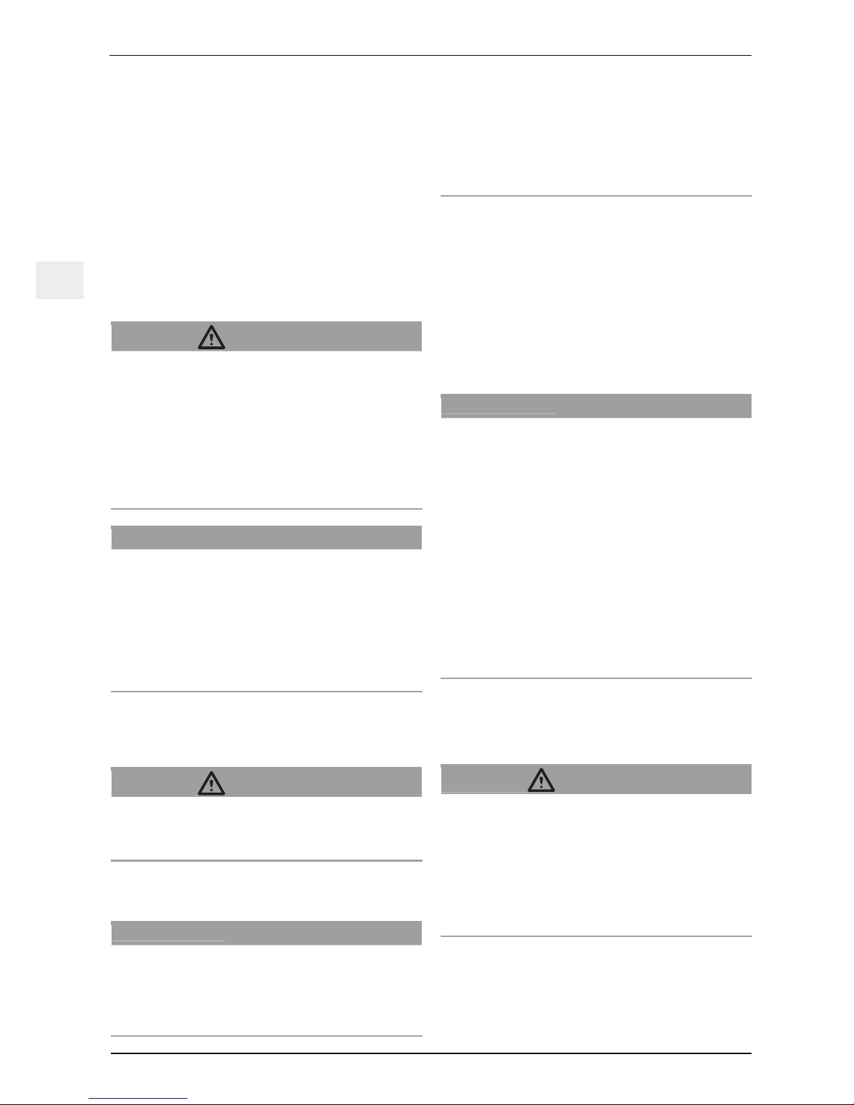
Technical Data / Technische Daten / Données techniques / Technische
gegevens
tirak
TM
rope
Hoist
Load-carrying
capacity
4)
Wire rope speed
6)
Connection
Power
Nominal
current
Diameter
Minimum
breaking load
5)
Weight
Dimensions / unit size
(see Fig. 2 and 3)
Temperature
range
3)
Noise
2)
tirak
TM
Seil
Winde
Tragfähigkeit
4)
Seilgeschwind-
igkeit
6)
Anschluss
Leistung
Nennstrom
Durchmesser
Mindest-
bruchkraft
5)
Gewicht
Abmessungen /
Einbaumaße
(siehe Abb. 2 und 3)
Temperatur-
bereich
3)
Geräuschent-
wicklung
2)
tirak
TM
câble
Treuil
Capacité de
charge
4)
Vitesse du câble
6)
Branchement
Puissance
Courant
nominal
Diamètre
Effort de rupture
minimal
5)
Poids
Dimensions /
Cotes de montage
(cf. Fig. 2 et 3)
Plage de tempé-
rature
3)
Emission so-
nore
2)
tirak
TM
kabel
Lier
Draagvermogen
4)
Kabelsnelheid
6)
Aansluiting
Vermogen
Nominale
stroom
Diameter
Min.
breukkracht
5)
Gewicht
Afmetingen/inbouwmaten
(zie Afb. 2 en 3)
Temperatuur-
bereik
3)
Geluidsont-
wikkeling
2)
a b c x/y
kg m/min
230 V
50 Hz
400 V
50 Hz
kW A
mm
kN
kg
mm mm mm mm
°C
dB
(A)
X 300 9 – x 0,5 1,6 27 437 262 265
X 301 9 x – 0,45 4,5 29 476 257 245
X 300
X 302
300
18 – x 0,9 2,6
8
14,7
27 437 262 265
∼ 250 /
250
-10
…
+50
1)
72
X 400 9 – x 0,75 2,8 29 437
X 401 9 x – 0,75 6,5 32 452
X 402 18 – x 1,5 5 31 496
X 400
X 403
400
9/18 – x 0,75/1,5 2,8/5,1
8
19,6
35 452
273 285
∼ 250 / 250
-15
…
+70
72
X 500 9 – x 0,9 2,8 40 489 265
X 501 9 x – 0,9 6,5 49 556 256
X 502 18 – x 1,8 5 43 504 265
X 500
X 503
500
9/18 – x 0,9/1,8 2,8/5,1
8
24,5
47 504
297
285
∼ 250 / 250
-10
…
+50
1)
70
X 800 9 – x 1,6 4,5 45 525 297 265
X 803 9/18 – x 1,75/3,5 4/8 49 550 297 285
X 805 4,5/9 – x 0,8/1,6 3/4,2 50 563 304 285
X 800
X 806
800
9/18 – x 0,8/3,2 3,6/9
8
39,2
71 603 328 315
∼ 250 / 250
-10
…
+50
1)
70
T 1000 9 – x 1,9 4,6 71 580 336 311
T 1003 9/18 – x 1,9/3,8 5,5/9,5 85 642 355 348
T 1005 4,5/9 – x 0,9/1,9 3,6/4,6 84 642 355 318
T 1000
T 1006
980
4,5/18 – x 0,9/3,8 4/9,7
8
48,1
94 679 386 348
∼ 250 / 250
-10
…
+50
1)
70
T 1020 9 – x 1,9 4,6 71 580 336 311
T 1023 9/18 – x 1,9/3,8 5,5/9,5 85 642 355 348
T 1025 4,5/9 – x 0,9/1,9 3,6/4,6 84 642 355 318
T 1020
T 1026
980
4,5/18 – x 0,9/3,8 4/9,7
9
48,1
94 679 386 348
∼ 250 / 250
-10
…
+50
1)
70
Page 3
tirak™
G932.1 - 06/2010 EN-DE-FR-NL–III
DE
FR
NL
ENEN
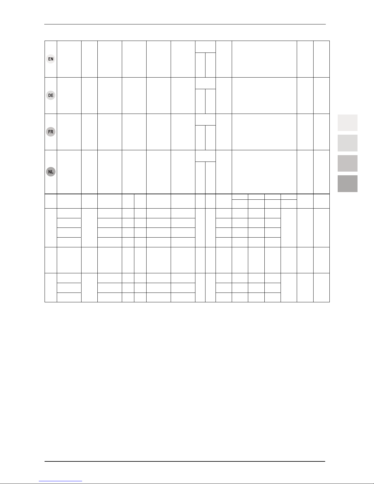
tirak
TM
rope
Hoist
Load-carrying
capacity
4)
Wire rope speed
6)
Connection
Power
Nominal
current
Diameter
Minimum
breaking load
5)
Weight
Dimensions / unit size
(see Fig. 2 and 3)
Temperature
range
3)
Noise
2)
tirak
TM
Seil
Winde
Tragfähigkeit
4)
Seilgeschwind-
igkeit
6)
Anschluss
Leistung
Nennstrom
Durchmesser
Mindest-
bruchkraft
5)
Gewicht
Abmessungen /
Einbaumaße
(siehe Abb. 2 und 3)
Temperatur-
bereich
3)
Geräuschent-
wicklung
2)
tirak
TM
câble
Treuil
Capacité de
charge
4)
Vitesse du câble
6)
Branchement
Puissance
Courant
nominal
Diamètre
Effort de rupture
minimal
5)
Poids
Dimensions /
Cotes de montage
(cf. Fig. 2 et 3)
Plage de tempé-
rature
3)
Emission so-
nore
2)
tirak
TM
kabel
Lier
Draagvermogen
4)
Kabelsnelheid
6)
Aansluiting
Vermogen
Nominale stroom
Diameter
Min. breukkracht
5)
Gewicht
Afmetingen/inbouwmaten
(zie Afb. 2 en 3)
Temperatuurbereik
3)
Geluidsont-
wikkeling
2)
Table/Tabelle/Tableau/Tabel 1
4)
X-model series from 1000 kg load carrying capacity: with mechanical load limiting device; X-model series from
1000 kg load carrying capacity: mechanical or electric load limiting device can be supplied as an option. T
Model series: electric load limiting device can be supplied as an option.
X-Typenreihe ab 1000 kg Tragfähigkeit: mit mechanischer Hubkraftbegrenzung; X-Typenreihe bis 1000 kg
Tragfähigkeit: mechanische oder elektronische Hubkraftbegrenzung optional lieferbar. T-Typenreihen:
elektronische Hubkraftbegrenzung optional lieferbar.
Série X à partir d'une capacité de charge de 1000 kg : avec limitation mécanique de la force de levage; série X
jusqu'à une capacité de charge de 1000 kg : limitation mécanique ou électronique de la force de levage disponible en option. Séries T : limitation électronique de la force de levage disponible en option.
X-type serie vanaf 1000 kg draagvermogen: met mechanische hefkrachtbegrenzing; X-type serie tot 1000 kg
draagvermogen: mechanische of elektronische hefkrachtbegrenzing optioneel leverbaar. T-type series:
elektronische hefkrachtbegrenzing optioneel leverbaar.
1)
expanded temperature range on request / erweiterter
Temperaturbereich auf Anfrage / extension de la plage de
température sur demande / uitgebreid temperatuurbereik op
aanvraag
2)
at a distance of 1m / in 1 m Abstand / à 1m de distance / op 1 m
afstand
3)
Depending on the ambient conditions (ambient temperature,
sunrays, etc.) as well as the possible thermal discharge (dirt, accumulated heat, etc.)
Abhängig von den Umgebungsbedingungen (Umgebungstemperatur, Sonneneinstrahlung, etc.) sowie der möglichen Wärmeabfuhr (Schmutz, Stauwärme, etc.)
En fonction des conditions ambiantes (température ambiante,
rayonnement solaire etc.) et de l'éventuelle évacuation de la chaleur (saleté, accumulation de chaleur etc.)
Afhankelijk van de omgevingsvoorwaarden (omgevingstemperatuur, zonbestraling, etc.) en van de mogelijke
warmteafleiding (vuil, warmteopstopping, etc.)
a b c x/y
kg m/min
230 V
50 Hz
400 V
50 Hz
kW A
mm
kN
kg
mm mm mm mm
°C
dB
(A)
X 1020 9 – x 1,9 4,6
45
525 297 265
X 1023 9/18 – x 1,9/3,8 4,5/8,5
56
563 307 315
X 1025 4,5/9 – x 0,9/1,9 3,5/4,8
55
563 307 285
X 1020
X 1026
980
4,5/18 – x 0,9/3,8 4/9,6
9
48,1
71
605 332 315
∼ 250 / 250
-15
…
+70
70
X 1530
X 1530 1500 9 – x 2,8 7
10
73,6
49
522 297 285
∼ 250 / 250
-15
…
+70
70
X 3050 6 – x 3,8 9,9
105
669 400 372
X 3052 12
– x
7,5 17
117
681 403 372
X 3050
X 3053
3000
6/12 – x 3,8/7,5 9,9/19
14
147,2
156
786 428 442
∼ 250 / 250
-15
…
+70
78,5
Page 4

tirak™
EN-DE-FR-NL–IV G932.1 - 06/2010
DE
FR
NL
ENEN
5)
Calculation of the required minimum breaking load Fo of the rope
(does not correspond to the actual, manufacturer-specific
minimum breaking load!):
Berechnung der erforderlichen Mindestbruchkraft F
o
des Seiles
(entspricht nicht der tatsächlichen, herstellerspezifischen
Mindestbruchkraft!):
Calcul de l’effort de rupture mininal requis F
o
du câble (ne
correspond pas à l’effort de rupture minimal effectif et spécifique
du fabricant!) :
Berekening van de minimum breukkracht Fo van de kabel (komt
niet overeen met de daadwerkelijke fabrikantspecifieke min.
breukkracht!):
Fo = Zp x S
F
o
= 5 x S [kg] x 9,81 [N/mm²]
Fo: smallest guaranteed breaking load of the wire rope / kleinste garantierte
Bruchlast des Drahtseils / Charge de rupture minimale garantie du câble
métallique / kleinste gegarandeerde breuklast van de draadkabel
Z
p
: = 5: Expansion coefficient of the wire rope / Ausnutzungskoeffizient des
Drahtseils / Coefficient d’utilisation du câble métallique /
Belastingscoëfficiënt van de draadkabel
S: Maximum static load on the wire rope (load capacity of the hoist) / maximal
statische Zuglast im Drahtseil (Tragfähigkeit der Winde) / Charge statique
maximale du câble métallique (capacité de charge du treuil) / Maximale
statische treklast in draadkabel (draagvermogen van de lier)
6)
In accordance with DIN 15020 the devices correspond to drive group 1 Bm at rope speeds of up to 9
m/min, and to drive group 1 C
m
at a rope speed exceeding 9 m/min. The average operating time per
day with relation to a year (operating time class) depends on the actual load (load spectrum). /
Geräte entsprechen gemäß DIN 15020 bei Seilgeschwindigkeiten bis 9 m/min der Triebwerksgruppe
1 B
m
, über 9 m/min Seilgeschwindigkeit der Triebwerksgruppe 1 Cm. Die mittlere Laufzeit je Tag
bezogen auf ein Jahr (Laufzeitklasse) ist abhängig von der tatsächlich auftretenden Belastung
(Lastkollektiv). /
Appareils conformément à DIN 15020 pour les vitesses de défilement du câble jusqu'à 9 m/min dans
la catégorie de mécanismes de treuil 1 B
m
, vitesse de défilement du câble supérieure à 9 m/min dans
la catégorie de mécanismes de treuil 1 C
m
. La durée de vie moyenne par jour rapportée à un an
(classe de durée de vie) est fonction de la charge réelle sur le câble (spectre de charge). /
Apparaten voldoen volgens DIN 15020 bij kabelsnelheden tot 9 m/min aan de eisen van de
drijfwerkgroep 1 B
m
, boven 9 m/min kabelsnelheid aan de eisen van drijfwerkgroep 1 Cm. De
gemiddelde looptijd per dag gerelateerd aan een jaar (looptijdklasse) is afhankelijk van de
daadwerkelijk optredende belasting (collectieve belasting)
Page 5
tirak™
G932.1 - 06/2010 EN-DE-FR-NL–V
DE
FR
NL
ENEN
Model series / Typenreihe / Série / Serie
T 1000
T 1020
Model series / Typenreihe / Série / Serie
X 3050
Model series / Typenreihe / Série / Serie
X 300
X 400
X 500
X 800
X 1020
X 1530
Fig./Abb./Fig./Afb. 1
Page 6
tirak™
EN-DE-FR-NL–VI G932.1 - 06/2010
DE
FR
NL
ENEN
Fig./Abb./Fig./Afb. 2
Model series / Typenreihe / Série / Serie
X 300
X 400
X 500
X 800
X 1020
X 1530
T 1000
T 1020
X 3050
Distance / Abstand / Distance / Afstand [mm]
A1-A2
A2-A3
A1-A4
d
e
f
255
220
220
–
–
–
300
267
267
–
–
–
449
250
250
14
28
56
570
360
360
–
–
–
Screw / Schraube / Vis / Schroef
A
B
Adapter
Strength /
Festigkeit /
Résistance /
Sterkte
M10
–
M12
8.8
M10
M16
M12
8.8
M16
–
–
8.8
M16
M30
–
8.8
Table/Tabelle/Tableau/Tabel 2
Fig./Abb./Fig./Afb. 3
Fig./Abb./Fig./Afb. 4
Page 7
tirak™
G932.1 - 06/2010 EN-DE-FR-NL–VII
DE
FR
NL
ENEN
Fig./Abb./Fig./Afb. 5
Fig./Abb./Fig./Afb. 6
Fig./Abb./Fig./Afb. 7
Fig./Abb./Fig./Afb. 8
Fig./Abb./Fig./Afb. 9
Page 8
tirak™
EN-DE-FR-NL–VIII G932.1 - 06/2010
DE
FR
NL
ENEN
Fig./Abb./Fig./Afb. 10
Fig./Abb./Fig./Afb. 11
Fig./Abb./Fig./Afb. 12
Fig./Abb./Fig./Afb. 13
Page 9
tirak™
G932.1 - 06/2010 EN-DE-FR-NL–IX
DE
FR
NL
ENEN
Fig./Abb./Fig./Afb. 14
Fig./Abb./Fig./Afb. 15
Fig./Abb./Fig./Afb. 16
Fig./Abb./Fig./Afb. 17
Page 10
tirak™
EN-DE-FR-NL–X G932.1 - 06/2010
DE
FR
NL
ENEN
Fig./Abb./Fig./Afb. 18
Fig./Abb./Fig./Afb. 19
Page 11
Installation and operating manual
G932.1 - 06/2010 EN-1
ENEN
Contents
1 General ............................................................................... 2
1.1 Terms and abbreviations used in this manual .......... 2
1.2 Symbols used in this manual ....................................3
2 Safety.................................................................................. 3
2.1 General safety instructions ....................................... 3
2.2 Instructions for the operator...................................... 4
3 Overview............................................................................. 4
3.1 Delivery state ............................................................ 4
3.2 Scope of delivery ...................................................... 4
3.3 Equipment description .............................................. 4
4 Description......................................................................... 6
4.1 Functional description............................................... 6
4.2 Components / Modules............................................. 6
4.3 Technical Specifications ........................................... 7
4.4 Operating fluids......................................................... 7
4.5 Circuit diagram.......................................................... 7
4.6 Operating unit ........................................................... 7
4.7 Safety equipment...................................................... 7
4.8 Anchoring.................................................................. 8
4.9 Increasing the load bearing capacity ........................ 8
5 Ropes.................................................................................. 8
6 Optional accessories......................................................... 8
7 Options ............................................................................... 8
8 Necessary accessories ..................................................... 9
9 Installation and commissioning....................................... 9
9.1 Directives and standards .......................................... 9
9.2 Checks to be undertaken before starting the
installation................................................................. 9
9.3 Assembly ................................................................ 10
9.4 Commissioning ....................................................... 12
10 Operating / Operation...................................................... 13
10.1 Checks to be carried out before starting work ........ 13
10.2 Operation................................................................ 13
10.3 Emergency descent ................................................ 14
10.4 Switching off when overloaded ............................... 14
11 Foreseeable misuse ........................................................ 14
12 Dismantling ...................................................................... 14
13 Shutting down.................................................................. 15
13.1 Work breaks............................................................ 15
13.2 Temporary shutdown .............................................. 15
13.3 Permanently decommissioning............................... 15
14 Transport and storage .....................................................15
14.1 Hoists.......................................................................15
14.2 Rope........................................................................15
15 Maintenance work ............................................................15
15.1 Authorized maintenance personnel.........................15
15.2 Mandatory inspections.............................................15
15.3 Reading the running hours counter .........................16
15.4 Care and maintenance ............................................16
15.5 Adjustment...............................................................17
15.6 Ordering spare parts................................................19
16 Disposal and environmental protection.........................19
17 Troubleshooting...............................................................20
18 EU Declaration of Conformity (Extract)..........................23
DANGER!
Risk of injury caused by falling objects, malfunctions,
incorrect usage and incorrect operation!
Failure to follow these instructions:
can result in severe injuries or death,
can result in damage to the equipment.
– Read through this operating manual carefully before you
install and commission this machine.
– Follow the instructions and procedures specified in this
manual in order to ensure safe operation of the equipment.
Page 12

Installation and operating manual
EN-2 G932.1 - 06/2010
ENEN
1 General
Date of issue
June 2010
Copyright
The copyright of this instruction manual remains with Greifzug
Hebezeugbau GmbH.
This instruction manual is intended only for the operators of the
systems described here and their staff. This instruction manual
must be available to the operating personnel at all times. Additional copies can be obtained on request.
No part of this instruction manual may be reproduced, distributed
or otherwise communicated without the permission of Greifzug
Hebezeugbau GmbH.
Legal proceedings may be implemented in the case of any infringements.
Manufacturer's address
Sales and service office:
Greifzug Hebezeugbau GmbH
Scheidtbachstraße 19-21
51469 Bergisch Gladbach, Germany
Postfach 20 04 40
51434 Bergisch Gladbach, Germany
Tel: +49 (0) 22 02 / 10 04-0
Fax: +49 (0) 22 02 / 10 04-50 + 70
Greifzug Hebezeugbau GmbH reserves the right to make
changes to the product described in this instruction manual as
part of their ongoing product improvement programme.
Customers can obtain documentation about other TRACTEL
products by requesting the documentation from companies within
the TRACTEL Group or service organisations appointed by the
TRACTEL Group. Please visit our TRACTEL website at:
www.tractel.com for further details regarding the hoisting gear
and related accessories; stationary or mobile working platforms
for moving around on the inside and outside of buildings; rigging;
block stops for heavy loads; personal safety harnesses to prevent falls; traction and rope tension measuring equipment, etc.
The TRACTEL Group and its dealer network also provide additional customer and repair services upon request.
1.1 Terms and abbreviations used in
this manual
The terms used in this instruction manual have the following
meanings:
System / Machine
Pursuant to the Machine Directive 2006/42/EC lifting equipment,
hoisting gear and rigging for lifting are regarded as machines.
The term "system" or also "machine" describes the device in
which the unit described here will be fitted.
System manufacturer
The system manufacturer (system planner, system manufacturer,
installer) is the company marketing the system and all of the
required components. The system manufacturer is responsible
for the design, manufacturing, assembly and marketing.
Rigging
Rigging consists of equipment which does not belong to the
hoisting gear and which creates a connection between the carrying means and the load or the carrying means and the load lifting
equipment (e.g. rope loops, round slings, shackles, swivel hooks,
eye hooks, deflection rollers).
Anchoring point
Part of the on-site suspended construction to which the suspension rope, the safety rope, deflection rollers or the hoisting gear
is anchored.
Operating personnel
Personnel who have been trained by the operator to operate the
product and are authorised to operate it.
Operator
The operator is responsible for the correct operation of the system / equipment and also for adhering to the maintenance intervals and the undertaking of the service work.
Electrician
An electrician is someone who possesses sufficient knowledge
or has obtained the required qualification through training in
order to recognise the risks and avoid the dangers that can occur
when working with electricity.
Independent secondary brake
A device for stopping the load lifting equipment in the event of
the suspension rope snapping or a malfunction, e. g. drive malfunction.
Hoisting gear / machine for lifting loads
Device or equipment consisting of a device with load carrying
means for lifting or transporting loads (e.g. wire rope hoist or wire
rope hoist with rope and swivel hook).
Customer / end customer
The customer or end customer is the system manufacturer's
customer and can also be the operator.
Load lifting equipment (LAM)
A component or piece of equipment which does not belong to the
hoisting gear, which enables the load to be grasped and which is
attached between the machine and the load or to the load itself,
or is intended to be an integral component of the load. Rigging
and its components are also regarded as load lifting equipment.
Material lifting equipment (MAM)
Load lifting equipment for material.
Nominal load
The nominal load is the load bearing capacity of the hoist and is
the load that is applied to a certain position, e.g. on a deflection
roller. Simple reeving doubles the nominal load.
Page 13

Installation and operating manual
G932.1 - 06/2010 EN-3
ENEN
Specialist
An appointed person who has undergone the appropriate training
and who, due to his knowledge and practical experience, is able
to safely perform the required work when provided with the necessary instructions.
tirak™
tirak™ is used in the text as the abbreviation for the hoist.
Load bearing capacity
The load bearing capacity specifies the maximum load the hoist
is allowed to lift or pull. The load bearing capacity can be multiplied by reeving the rope.
Carrying means
The carrying means is equipment connected to the hoisting gear
for attaching load lifting equipment, rigging or loads (e.g. a hook
permanently attached to the suspension rope).
Maintenance personnel
A person appointed by and trained by Greifzug Hebezeugbau
GmbH with a valid certificate, who is capable of safely performing
the required maintenance, inspection and service work when
provided with the required instructions.
1.2 Symbols used in this manual
DANGER!
Type and source of danger
Result: e.g. death or severe injuries.
– Measures that must be taken to eliminate the danger.
ATTENTION!
Type and source of danger
Result: e.g. equipment or environmental damage.
– Measures that must be taken to eliminate any possible
damage.
Note:
This symbol is not used to indicate safety information but to
indicate information that will give you a better understanding o
f
the working procedures.
2 Safety
2.1 General safety instructions
DANGER!
Danger of severe injuries caused by malfunctions, incorrect use and incorrect operation!
– You must abide by the following instructions in order to
ensure safe operation and correct functioning of the
equipment!
– Please observe the special safety instructions for all of
the work to be performed as described in the individual
chapters in this manual.
– Faulty or damaged hoists, ropes, rigging or power supply
and control cables must never be used!
– The hoists may only be used with an original tirak™ wire
rope with the specified wire rope diameter.
– Rope, hoist and rigging must not be soiled by heavily soiling
building materials such as concrete, epoxy resin or other
adhesive materials. Protect the components against soiling!
Use the brush attachments to clean the rope when working
in an extremely dirty environment.
– Abide by the rope's withdrawal criteria, see ' 15.4 Care and
maintenance, Rope' on page 16.
– Cleaning the wire rope or the hoist with high pressure
cleaners is prohibited! Moisture results in malfunctions and
damage to the motor, brake and the electrical equipment.
– Dirt on the wire rope will result in premature wear or the
corrosion of the wire rope, rigging and hoist.
– Abide by the instructions concerning transport, storage and
cleaning listed on page 15.
– Always comply with the safety specification sheets provided
by the relevant manufacturers covering the lubricants to be
used.
– The anchoring devices must comply with the instructions
given in this manual or the applicable directives / standards.
– Never exceed the permitted load bearing capacity.
– Motors can become hot whilst working. Never touch the
motors.
– Operation without rubber plugs on the motor (Position 3, see
Fig. 15) is prohibited. Moisture can impair the effectiveness
of the brake. Risk of injury on the exposed motor shaft.
– Working outdoors during lightning or a storm is prohibited.
Danger of lightning strikes or the load being tipped over by
gusts of wind.
– Local climate and weather conditions must always be taken
into consideration during the planning stages: If in doubt,
you must request the weather and wind forecast from the
meteorological office before beginning work.
– Maintenance and repair work must only be undertaken by
authorised service personnel, see ' 15.1 Authorized mainte-
nance personnel' on page 15.
Page 14

Installation and operating manual
EN-4 G932.1 - 06/2010
ENEN
– Only qualified personnel who have been trained on the
system are permitted to install and operate it in compliance
with the instructions given in this instruction manual.
– Private users are obliged to obtain training in the assembly,
operation and maintenance of the unit by Greifzug Hebezeugbau GmbH.
– Only qualified electricians or trainees supervised by a quali-
fied electrician are permitted to undertake work on the electrical equipment in accordance with the electro technical
standards, rules and regulations.
– Never stand beneath suspended loads. Cordon off the
hazard zone whenever necessary.
– Never grasp the wire rope while the machine is operating.
– Never reach into the hoist's inlet or outlet whilst the machine
is operating. Risk of being pulled in and crushed.
– Hearing protection may be necessary, depending on how
the hoist is installed.
– If the load cannot be guided by on-site means then a low-
twist wire rope with a swivel hook or a rope swivel must be
used.
2.2 Instructions for the operator
– If more than one person is entrusted with the tasks men-
tioned above then the operator must appoint a supervisor
who is authorised to issue instructions.
– The operator is also responsible for preparing clear operat-
ing, maintenance, repair and other working instructions and
ensuring that the unit is operated correctly by instructing and
training the personnel in the correct and approved utilisation
methods.
– The operator is responsible for the correct operation of the
system as well as for adhering to the maintenance periods
and the undertaking of the service work.
– The operator is committed to maintaining the logbook sup-
plied with the system.
– You must always abide by the national accident prevention
regulations. EU Directive 89/391/EEC applies within the
European Union (in Germany Betriebssicherheitsverord-
nung (BetrSichV)). You must always abide by your country's
national accident prevention regulations.
– You must provide suitable protective equipment such as
safety gloves, hearing protectors and a fall prevention sys-
tem. Protection against extreme weather conditions (e.g.
sun protection, protection against cold) are also considered
to be part of the personal protective equipment.
– Always ensure that the workplace is sufficiently lit.
– A copy of these operating instructions must be provided and
readily available to the responsible personnel at all times.
– As Greifzug Hebezeugbau GmbH does not know the appli-
cations that the hoist described here will be used for in the
future, the system operator is therefore committed to inform-
ing their personnel about any new safety instructions as well
as any supplementary maintenance work.
– The system operator is responsible for selecting the anchor-
ing method and suitable rigging options.
– The anchoring devices must comply with the instructions
given in this manual or the applicable directives / standards.
– The use of non-original parts, in particular the use of other
than the prescribed original tirak™ wire ropes, will invalidate
the warranty of the manufacturer as well as the CE approval.
– Adhere to the permitted temperature range, see Table 1 on
page III.
3 Overview
3.1 Delivery state
The hoist is delivered completely assembled.
3.2 Scope of delivery
Hoist with control and connecting cable (wired fixed) in
accordance with the order specifications
tirak
TM
wire rope in accordance with the order specifications
Original Installation and operating manual
Circuit diagram
Logbook
Test certificate
CE Declaration of Conformity
Limit switch for switching off the lifting and pulling motions in
accordance with the order specifications.
Optional scope of delivery:
Button panel, pluggable
Central control unit, pluggable
Electronic or mechanical load limiting device
Deflection roller
Brush attachments for cleaning the ropes
The lengths of the control cable and the connecting cable are
determined when ordering. See also ' 6 Optional accessories' on
page 8, ' 7 Options' on page 8 and 'Electrical connection' on
page 10.
3.3 Equipment description
Approved use
The hoists are designed for raising and lowering as well as pulling and releasing or moving loads. Transporting personnel is
prohibited. The hoist is suitable for commercial as well as private
use. The precise intended use will be defined by the operator or
the system manufacturer.
Page 15

Installation and operating manual
G932.1 - 06/2010 EN-5
ENEN
Hooks, shackles and eyes or other optional carrying means
belonging to the device may only be used in combination with
this device.
X-Model series:
The rope infeed is on the motor side (observe the arrow on the
casing!). This corresponds to the load side of the hoist. The rope
outfeed is on the unloaded side of the hoist. The unloaded side
of the hoist may be loaded with a maximum of 100 kg (e.g. via
the rope pre-tensioning).
T-Model series:
The hoist can be pulled in both directions. Depending on the
running direction, the rope infeed is either on the motor side or
on the opposite side.
When pulling the rope pretension must not exceed 400 kg (see
Fig. 8 g/h).
The hoists may only be used with an original tirakTM wire rope
with the specified wire rope diameter.
If the load cannot be guided by on-site means then a low-twist
wire rope with a swivel hook or a rope swivel must be used.
Maintenance and repair work must only be undertaken by authorised service personnel, see ' 15.1 Authorized maintenance per-
sonnel' on page 15.
Greifzug Hebezeugbau GmbH declares that the machine described in this instruction manual complies with technological
safety standards that were applicable to the equipment in the
European Union when it was launched on the market by the
manufacturer.
Commissioning the machine is prohibited until the machine in
which this is installed complies as a whole with the regulations of
the 2006/42/EC Directive, the corresponding national legislation
for implementing the regulations in accordance with national law
and the corresponding declaration of conformity has been issued.
The operator or system manufacturer must perform a risk evaluation in accordance with Appendix I of the guideline 2006/42/EC
for machines for raising loads. EN 14492-1 must also be taken
into account when inspecting the equipment.
Any use other than that described here will be considered to be
unauthorised. Greifzug Hebezeugbau GmbH does not accept
any liability for damages resulting from unauthorised use. The
operator must assume sole responsibility in this case. Abiding by
all of the instructions given in this instruction manual, in particular
the installation and maintenance regulations, are also considered
part of authorised use.
Guarantee and liability exclusions
See ' 11 Foreseeable misuse' on page 14.
Application areas
The hoist is suitable for use under the following operating conditions:
For permanent or temporary installations
For short-term operation: Drive groups see Table1 on
page III.
At heights of up to 1,000 m above sea level (max)
Permitted temperature range see Table 1 on page III
DANGER!
Danger of severe accidents!
– 24-hour operation is prohibited.
– Use in areas where there is a risk of explosion is prohib-
ited.
– Use in a corrosive environment is prohibited.
1)
– Use in close proximity to open fire or in an extremely hot
environment is prohibited.
– Transport of persons is prohibited!
1)
Corrosion protection in accordance with order specifications
Installation example
See Fig. 8.
Structural requirements
Structural equipment for anchoring the hoist must possess a load
bearing capacity at least four times that of the hoist.
Please note that the load on the deflection roller, rigging and the
anchoring point increases depending on the arrangement of the
hoisting gear, deflection roller and load! See ' 4.9 Increasing the
load bearing capacity' on page 8.
The path of the hoist for lifting must be limited by one or multiple
limit switches, so that the upward and / or downward movement
is stopped. The operator or the system manufacturer must determine the design and the fitting position of the limit switches
when taking their risk assessment into account.
The operator or system manufacturer must install a limit switch
and, if necessary, an emergency limit switch and a floor limit
switch and connect them to the hoist. The limit switch must have
a positive opening. The clearance to the wire rope anchoring or
protruding components must be at least 1.5 m.
The wire rope must be long enough that the connection of the
rope end or the end of the rope cannot be called into the hoist
housing or the deflection roller.
If the load cannot be guided by on-site means then a low-twist
wire rope with a swivel hook or a rope swivel must be used.
It must be possible to position the operating equipment in such a
way that safe operation is always possible.
Rope, hoist and rigging must not be soiled by heavily soiling
building materials such as concrete, epoxy resin or other adhesive materials. The components must be protected against soiling.
Page 16

Installation and operating manual
EN-6 G932.1 - 06/2010
ENEN
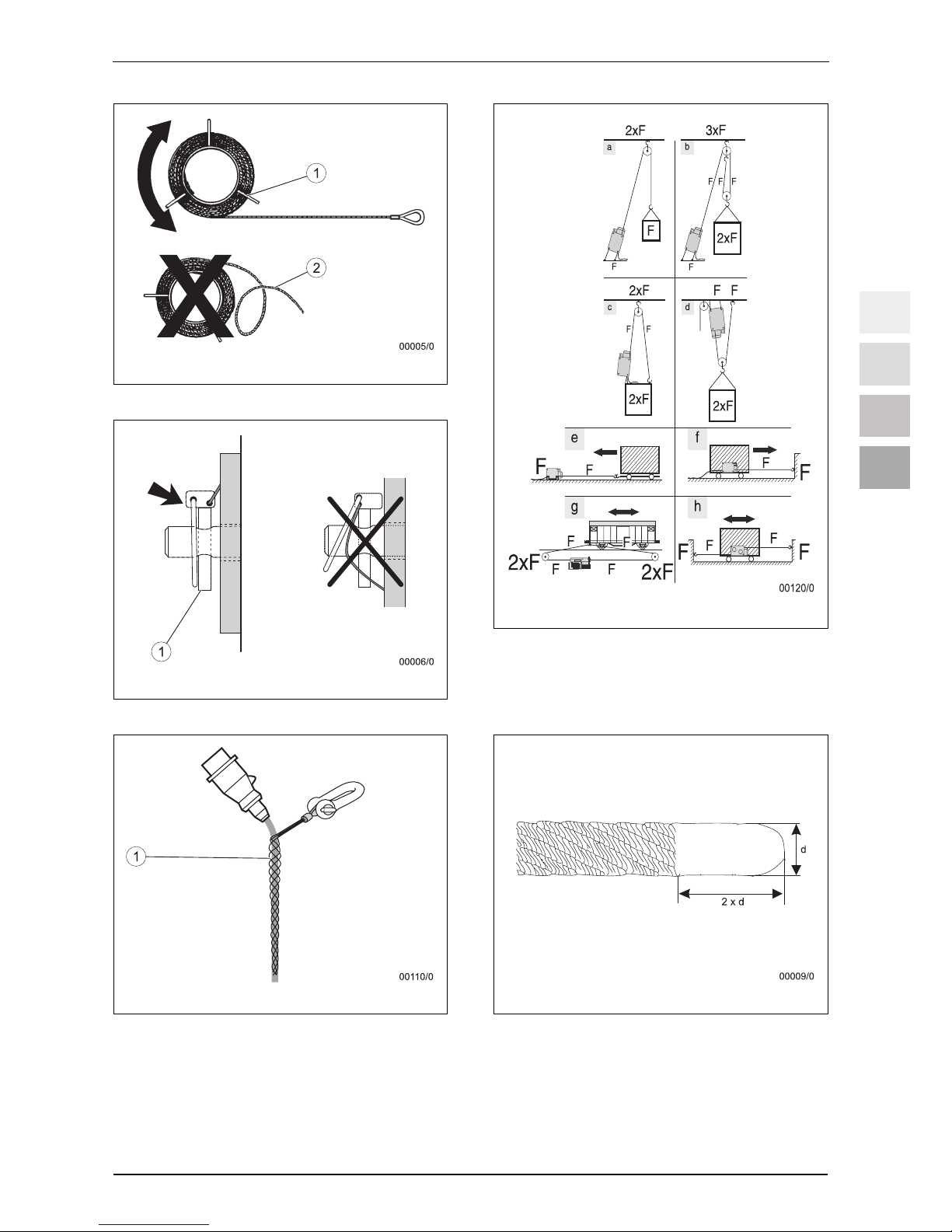
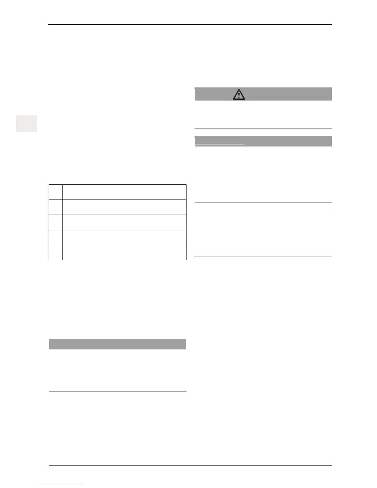
Nameplate and warning signs / application restrictions
See Fig. 10.
Item Name
1 Warning sign 'Wire rope diameter'
2 tirak™ nameplate
3 Brake nameplate
4 Electric motor nameplate
5 Emergency descend warning sign
6 Rope identification
The necessary information can be obtained from the nameplate.
Directives and standards
Applicable directives and standards: See ' 9.1 Directives and
standards' on page 9.
Product versions covered in the manual
The product versions described in this manual are listed in
Table 1 on page III.
Running hours counter
The running hours counter is located in the hoist's terminal box.
The running hours counter counts the time in which the hoist is in
operation as running hours (UPWARD or DOWNWARD movements). To read the running hours counter: See ' 15.3 Reading
the running hours counter' on page 16.
4 Description
4.1 Functional description
The tirakTM is a hoist for raising and lowering loads. The hoist is
operated with an electric motor.
The X-model series hoists can raise and lower as well as pull
and release in the pulling direction of the rope.
The T-model series hoists can pull in both directions and are
used, for example, for moving loads.
Operation is carried out via a button panel, control box or a central control unit.
The electromagnetic spring-applied brake automatically locks
when the operating control for travelling UP or DOWN is released
or when the power fails. A centrifugal brake prevents rope
speeds that are too high when lowering the load manually.
The load bearing capacity of the hoist can be multiplied according to the block and tackle principle by reeving the rope. See
' 4.9 Increasing the load bearing capacity' on page 8.
Press the EMERGENCY OFF button to stop the hoist immediately in an emergency situation.
X-Model series:
Hoists with a load bearing capacity of 1,000 kg or greater have a
mechanical load limiting device. Hoists with a load bearing capacity of 1,000 kg or greater can be optionally equipped with an
electrical or a mechanical load limiting device.
The load limiting device turns off the hoist at the latest once the
load reaches 1.25 times the load bearing capacity.
T-Model series:
Hoists of the T-model series can be optionally equipped with an
electrical load limiting device.
The load limiting device turns off the hoist at the latest once the
load reaches 1.25 times the load bearing capacity.
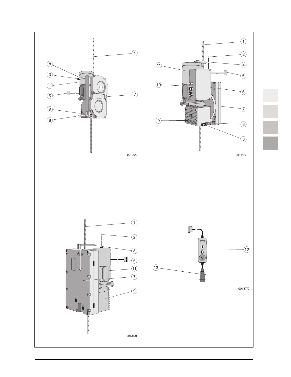
4.2 Components / Modules
See Fig. 1.
Item Name
1 Rope
2 Plug connector for the limit switch
3 Brake magnet lever
4 Handle
5 Plug connector for control unit1)
6 Terminal box (with optional running hours counter)
7 Rope drive
8 Carry handle
9 Gearbox
10 Operating unit1)
11 Motor
12 Controls (button panel)1)
13 Connecting plug
14 Limit switch (not shown)
1)
Optional scope of delivery, dependent on the hoist version and the
order specifications
Page 17

Installation and operating manual
G932.1 - 06/2010 EN-7
ENEN
4.3 Technical Specifications
The technical specifications are listed in Table 1 on page III.
4.4 Operating fluids
Transmission oil (hoist)
Mineral oil1) Synthetic oil2)
Temperature
range
-10…+50 °C -15…+70 °C
API specification
SAE85W-140 GL5 CLPPG or
PGLP ISO VG 460
Type Aral HYP85W-140 Klübersynth GH6 460
1)
Model series: X 300, X 500 to T 1020
(Identification: Oil drain plug with socket head screw)
2)
Model series: X 400, X 1020 to X 3050
(Identification: Oil drain plug with hexagon head screw)
In normal cases, it is not necessary to change the transmission
oil.
ATTENTION!
Incorrect transmission oil!
Damage to the gearbox due to insufficient lubrication.
– Use only the lubricants specified in the table.
Synthetic oil and mineral oil may not be mixed!
– Thoroughly flush the gearbox repeatedly with the new oil
type when changing the oil type.
– Change the oil drain plug to correspond with the new oil
type (socket head screw: mineral oil; hexagon head
screw: synthetic oil).
Lubricant
Application Lubricant
Traction sheave external
teeth (only model series
X 3050)
hebro-chemie VARILUB
or Klüber Grafloscon C-SG 0 Ultra
or Klüber C-SG 1000 Ultra
Quantity approx. 10 cm³ per lubrication
Rope Multipurpose oil/grease (without disulphide)
4.5 Circuit diagram
The circuit diagram is located in the terminal box of the motor.
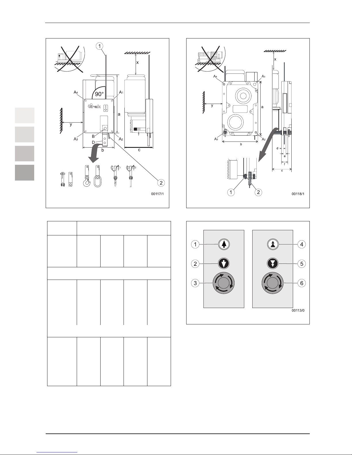
4.6 Operating unit
Depending on the product version the hoist is controlled by a
button panel, control box or a central control unit, see Fig. 1 and
Fig. 4.
Item Name Function
Devices with one speed
1 UP button Move load upwards / pull rope:
– Press and hold the button
2 DOWN button Move load downwards / release rope:
– Press and hold the button
3 EMERGENCY
OFF button
Turn on the device:
– Turn to the right until the button
releases
Disconnecting power supply:
– Press the button in
Devices with two speeds
4 UP button Move load upwards /pull rope:
– Press the button halfway and hold:
slow
– Press the button completely and hold:
fast
5 DOWN button Move load downwards / release rope:
– Press the button halfway and hold:
slow
– Press the button completely and hold:
fast
6 EMERGENCY
OFF button
See Point 3.
4.7 Safety equipment
EMERGENCY OFF button
The hoist is stopped immediately in an emergency situation by
pressing the EMERGENCY OFF button.
Mechanical load limiting device
X-Model series:
y From 1,000 kg load bearing capacity
y Up to 1,000 kg load bearing capacity optional scope of
delivery
The load limiting device switches off automatically if overloading
occurs. When delivered, the load limiting device has been set in
such a way that it deactivates the hoist at the latest once the load
reaches 1.25 times the load bearing capacity.
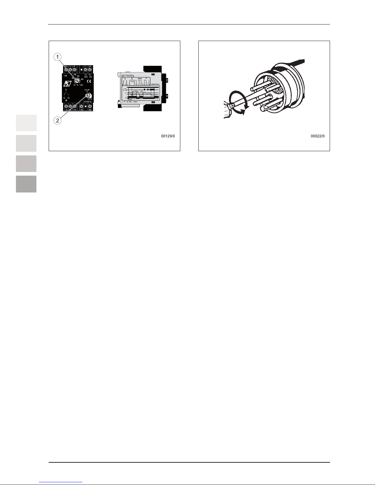
Electric load limiting device (optional)
The electric load limiting device switches off automatically in
case of an overload. The load limiting device reacts to the power
consumption of the motor. Hoists with two speeds are equipped
Page 18

Installation and operating manual
EN-8 G932.1 - 06/2010
ENEN
with two electric load limiting devices. An overload is recognised
when lifting. When delivered, the load limiting device has been
set in such a way that it deactivates the hoist at the latest once
the load reaches 1.25 times the load bearing capacity.
Spring-applied brake
The electromagnetic spring-applied brake automatically locks
when the operating control for travelling UP or DOWN is released
or when the power fails.
Centrifugal brake
A centrifugal brake on the motor shaft of the hoist ensures that
the load is not lowered too fast when the spring-applied brake on
the hoist’s motor is released manually.
Limit Switch / emergency limit switch
The path of the hoist for lifting must be limited by one or multiple
limit switches, so that the upward and / or downward movement
is stopped. The operator or the system manufacturer must determine the design and the fitting position of the limit switches
when taking their risk assessment into account.
The operator or system manufacturer must install a limit switch
and, if necessary, an emergency limit switch and a floor limit
switch and connect them to the hoist. The limit switch must have
a positive opening.
EN 14492-1 must also be taken into account when inspecting the
equipment.
Running hours counter
The running hours can be read from the running hours counter,
in order to determine when the next hoist safety check must be
carried out.
Phase sequence relay (hoists without converter)
In control units operating by three-phase current, the phase
sequence relay shuts down the system in the case of an incorrect phase sequence and this prevents an UP / DOWN travel
direction mix-up, which could potentially disable the limit switches
and load limiting devices.
4.8 Anchoring
The hoist can be anchored with and without an adapter (see pos.
D in Fig. 2).
Anchoring without adapter: At least 2 screws with a minimum
strength class of 8.8 with self-locking nuts.
Anchoring with adapter: 2 screws with a minimum strength class
of 8.8 with self-locking nuts.
Bolts that have at least the same strength and a similar quality
for securing can be used instead of the screws.
See also ' 9.3 Assembly' on page 10.
4.9 Increasing the load bearing capacity
DANGER!
Incorrect anchoring! Incorrect usage!
Risk of being injured by falling objects!
The load on the deflection roller, rigging and the anchoring
point increases depending on the arrangement of the hoisting
gear, deflection roller and load!
– The minimum breaking strength of the deflection roller,
the rigging and the anchoring point must be four times
greater than the nominal load of the hoist in the given installation situation (see Fig. 8).
The load bearing capacity of the hoist can be increased by reeving the rope, see Fig. 8 (F corresponds to the load bearing capacity of the hoist).
Note:
Reeving the rope reduces the hoist speed.
5 Ropes
DANGER!
Incorrect rope or rope with incorrect diameter!
Using an incorrect rope leads to a danger of falling or injury
through falling objects and the risk of malfunctions!
– In order to operate safely only use original ropes author-
ized by Greifzug Hebezeugbau GmbH with the correct
rope diameter and the required design.
– If the load cannot be guided by on-site means then a low-
twist wire rope with a swivel hook or a rope swivel must
be used.
– The required rope diameter is listed Table 1 on page III.
The design is listed Table 5 on page 17.
6 Optional accessories
The following accessories can also be purchased:
Deflection roller
Adapter, eye hook or master link
Please contact Greifzug Hebezeugbau GmbH directly.
7 Options
Please contact Greifzug Hebezeugbau GmbH directly.
Page 19

Installation and operating manual
G932.1 - 06/2010 EN-9
ENEN
8 Necessary accessories
The following accessories, which are not included in the scope of
delivery, are needed to be able to use the device:
Anchoring devices for the hoist (see ' 4.8 Anchoring' on
page 8).
Rigging equipment with a minimum breaking strength that
has four times the load bearing capacity of the hoist.
If the suspension rope is deflected or reeved: Deflection
rollers and rigging with a minimum breaking strength four
times greater than the nominal load of the hoist in the given
installation situation (see Fig. 8).
A longer connecting cable can be used if necessary, see
'Electrical connection' on page 10.
Other original Greifzug accessories: See ' 6 Optional accessories'
on page 8.
The operator or the manufacturer of the system is responsible for
selecting and using the accessories in accordance with the local
conditions. You must also abide by any other requirements of the
respectively applicable regulations and standards.
9 Installation and commissioning
9.1 Directives and standards
The machine fulfils the following directives and standards:
Machine Directive 2006/42/EC
DIN EN ISO 12100
Low voltage Directive 2006/95/EC
EN 60204
EN 14492; EN 14492-1/prA1:2009
The operator or the system manufacturer is responsible for ensuring that the machine is used within the limits specified in these
instructions. The operator or the system manufacturer must also
observe the directives and standards and EN ISO 14121 and
EN ISO 13849 for the machine in which the unit will be fitted.
9.2 Checks to be undertaken before
starting the installation
Check the rigging, deflection rollers and anchoring points
– Check to ensure that the deflection roller, the rigging and
the onsite anchoring point all have the necessary load bearing ratings and minimum breaking strength, see
' 4.9 Increasing the load bearing capacity' on page 8.
The maximum possible nominal load must be multiplied by 4
(operating coefficient) in order to calculate the necessary
load bearing capacity.
Inspecting the installation site
Check whether the hoist can be installed correctly without it
being obstructed by other system components. Observe the
required installation space in accordance with Fig. 2 and
Table 1 on page III. The installation space must not contain
any sharp or edged components.
Check that the mounting does not cover any nameplates
(see Fig. 10).
If necessary provide for notches.
Check whether the hoist can be mounted in such a way that
the rope feeds vertically into the hoist in the pulling direction
(Fig. 8).
Check whether a suitable connection for the power supply in
accordance with chapter 'Electrical connection' on page 10
is available on site.
Checking the hoists and the accessories
Hoists
– Check that the hoist and accessories are complete (see
' 3.2 Scope of delivery' on page 4 and ' 4.2 Components /
Modules' on page 6).
– Inspect the housing for signs of damage.
Rope
– Check whether the diameter and design of the rope match
the hoist, see Table 1 on page III.
If the load cannot be guided by on-site means then a low-
twist wire rope with a swivel hook or a rope swivel must be
used.
– Check that the length of the rope is sufficient:
It must be possible to safely move the load from the start to
the end position. The loose end of the rope must not reach
the hoist when lowering or releasing the load.
The rope end connection and the load bearing point or the
rope end must not be pulled into the the deflection roller.
– Inspect the entire length of the rope for any signs of damage,
see Fig. 12.
– Inspect the rope tip in accordance with Fig. 9 (see also
' 15.4 Care and maintenance, Rope' on page 16).
Anchoring devices
– Check whether the bolts/screws/rigging comply with the
specifications in ' 4.8 Anchoring' on page 8.
– Inspect the fishplates, load bolts and screw connections for
damage.
Connecting cable
– Check that the length is adequate.
– Check whether the cable diameter is sufficient for the
planned length (see Table 3 and 4 on page 11).
– Check the entire length of the cable for visible damage.
Page 20
Installation and operating manual
EN-10 G932.1 - 06/2010
ENEN
Control cable
– Check that the length is adequate.
– Check the entire length of the cable for visible damage.
9.3 Assembly
Requirements
Assembly may only be performed by trained personnel.
The workplace must have adequate lighting.
Anchor hoist
DANGER!
Incorrect anchoring!
Mortal danger of falling! Risk of being injured by falling objects!
– Only attach the hoist at the specified anchorage bore-
holes with the specified anchoring devices.
– The rope must run into the hoist vertically (see Fig. 2).
– If greater load bearing capacity is required: See the
specifications in ' 4.9 Increasing the load bearing capacity'
on page 8.
ATTENTION!
Incorrect installation position!
Damage to the equipment may occur!
The equipment will be damaged if incorrect or insufficient
lubricant is used!
– The hoist must not be mounted horizontally on the flat
side.
– Attach the hoist in such a way that the flat side only
points to the side or upward, see Fig. 2 and Fig. 3.
– Use screws with self-locking nuts to stop them from being
lost.
– Secure the bolts with a cotter pin or similar lock.
DANGER!
Cotter pins inserted incorrectly!
Risk of being injured by falling objects!
– Insert the cotter pin according to Fig. 6.
X-Model series
See Fig. 2 and Table 2 on page VI.
ATTENTION!
Incorrect anchoring!
Can result in damage to the device!
The unit can be damaged if fastened to the wrong anchorage
boreholes!
– Only attach the hoist at the specified anchorage bore-
holes with the specified anchoring devices.
– Securing to anchorage boreholes that are positioned
diagonally opposite one another is prohibited.
– Securing to the A3 + A4 anchorage boreholes in accor-
dance with Fig. 2 is prohibited.
Securing to anchorage points A:
– Secure the hoist to at least two anchorage points using
screws or bolts.
A1 + A2 or A2 + A3 or A1 + A4.
Securing to anchorage point B:
– Secure the hoist with screws or bolts.
T-Model series
See Fig. 3 and Table 2 on page VI.
ATTENTION!
Incorrect anchoring!
Can result in damage to the device!
The unit can be damaged if fastened to the wrong anchorage
boreholes!
– Only attach the hoist at the specified anchorage bore-
holes with the specified anchoring devices.
– If the load should be pulled from direction A2, use an-
chorage point A1.
– If the load should be pulled from direction A4, use an-
chorage point A3.
– If the load should be pulled in both directions, use an-
chorage points A1 + A3.
Damage to the fixing fishplates is possible!
– Screw on the self-locking nuts (1) only as far as until they
lie flush on the fishplate (2).
– Fasten the hoist to anchorage points A1 or A3 or A1 + A3
using screws or bolts.
Electrical connection
DANGER!
Danger through unauthorised use!
The electrical connection on the operator's side must be
connected in such a way that the hoist can be secured against
unauthorised use! Suitable protective measures include:
– Lockable Emergency Off device
– Lockable main switch
– Key-switch
– Removable operating controls
The electric connection must be established in accordance with
EN 60204-32.
The equipment must be earthed via the power supply cable. The
earthing function must be tested (isolation inspection). Additional
measures, such as earthing the supporting cable, may be necessary.
Page 21
Installation and operating manual
G932.1 - 06/2010 EN-11
ENEN
If necessary, a generator with three times the specified power
rating of the hoist can be utilised (e.g.: 2 hoists x 2.2 kW x 3 =
13.2 kVA). The generator must be earthed by the operator. The
earthing function must be tested (isolation inspection).
The existing connection used must be equipped with a 30 mA
safety switch (FI or RCD) and overload protection (automatic
circuit breaker with K- feature) in accordance with the circuit
diagram and the order specifications. The starting current is three
times the nominal current of the hoist.
Three-phase current: 400 V (3P + N + PE), 50 Hz
Alternating current: 230 V (P + N + PE), 50 Hz
The longer the power supply cable, the larger the cable crosssection must be.
– Secure hanging cables with cable ties (1), see Fig. 7.
– Use heavy duty rubber lines with support elements.
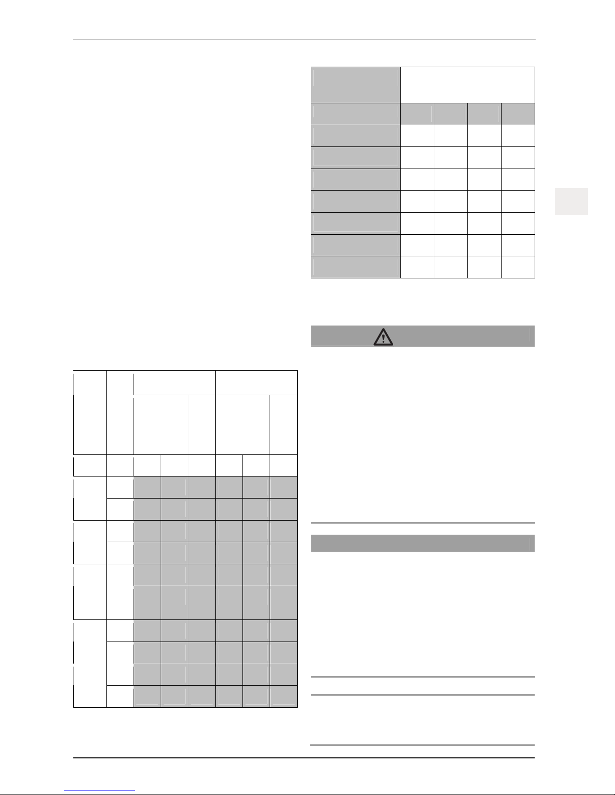
Determining the required cable cross-section:
– Determine the code letter (e.g. 'C') using Table 3. On hoists
with two speeds the maximum rope speed is the determining factor.
– In Table 4 determine the cable cross-section required for the
code letter.
one hoist two hoists
Model series
max. rope speed
Three-phase
current
Alternating
current
Three-phase
current
Alternating
current
m/min 400 V 230 V 230 V 400 V 230 V 230 V
9 A B C A D E X 300
18 A C - B E -
9 A C E B E F X 400
X 500
18 B E - D G -
9 B E - D F - X 800
T 1000
T 1020
X 1020
18 C F - E G -
9 B E - D - - X 1530
18 C F - F - -
6 D F - F G - X 3050
12 E F - F G -
Table 3
Code letter Cable cross-section [mm²]
for cable lengths up to…
20 m 50 m 100 m 200 m
A 1.5 1.5 1.5 1.5
B 1.5 1.5 1.5 2.5
C 1.5 1.5 2.5 4
D 1.5 2.5 4 6
E 1.5 2.5 4 10
F 1.5 4 10 16
G 2.5 6 10 16
Table 4
Mount the rope
DANGER!
Risk of injury through stabs and cuts!
Broken wires in the wire rope can result in protruding wires!
Protruding wires can cut or stab through safety gloves!
– Wear suitable leather protective gloves when working
with wire ropes.
– Never let the wire rope run through your hands!
Danger of crushing or being pulled in!
When threading the rope in there is a risk of fingers or the
entire hand being pulled in with the rope or being crushed on
the pulleys and rope guides!
– Never touch the rope whilst the hoist is in operation! Do
not reach into the inlet or outlet of the hoist.
– Maintain a suitable distance from the rope.
– Watch out for rope loops.
ATTENTION!
Incorrect assembly!
Damage to the rope may occur!
– The rope must never run over an edge!
– The loose rope end must hang free.
Damage to the hoist possible (X-model series)!
– The unloaded side of the hoist may be loaded with a
maximum of 100 kg (e.g. via the rope pretensioning).
Damage to the hoist possible (T-model series)!
– When pulling the rope pretension must not exceed
400 kg (see Fig. 8 g/h).
Note:
If the anchoring point for the rope is located above the hoist the
rope must be fastened before it is fed into the hoist.
Page 22
Installation and operating manual
EN-12 G932.1 - 06/2010
ENEN
– Roll-off the rope correctly so that no loops in the rope occur.
– Insert the tip of the rope into the hoist as far as possible.
(X-Model series: Observe the direction of the arrow on the
casing.)
– Switch on the hoist in the pulling direction.
– Feed in the rope until the rope feeds automatically and
comes out of the opening on the other side.
– Make sure that the rope outlet is free to allow the loose end
to untwist.
– If necessary, guide the loose end of the rope over a pulley
or another suitable rope guide to prevent the rope from run-
ning over an edge that will result in the rope being damaged.
See Fig. 11.
– Place the loose end of the rope down correctly to prevent
any loops or knots from being created.
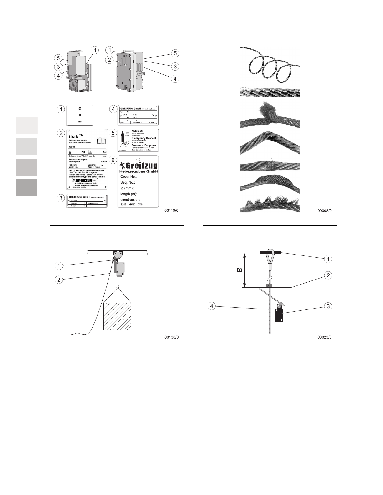
Mount and set limit switch
See Fig. 13.
Item Name
1 Rope anchoring
2 Stop disc
3 Limit switch (similar to illustration)
4 Suspension wire rope
The path of the hoist must be limited by one or multiple limit
switches (3), so that the upward and/or downward movement is
stopped.
The stop disc (2) must be mounted below the rope anchoring (1)
on the suspension wire rope (4). The distance to the rope anchoring (1) or the protruding components must be at least 1.5 m
(dimension a).
9.4 Commissioning
ATTENTION!
Incorrect load anchoring!
Can result in damage to the device!
The load must not be directly attached to the towing rope.
– Use a wedge clamp and an anchorage rope to anchor
the load.
Determine operational readiness
– Check the rope anchoring.
– Check the anchoring of the hoist, deflector rollers and the
load.
– Check whether the rope enters the hoist vertically.
– Check that the rubber plugs on the motor (see Fig. 15,
Position 3) are sitting in the correct position.
– Record the inspection results in the logbook.
Functional test
DANGER!
Risk of being injured by falling objects!
– Never stand beneath suspended loads.
– Cordon off the hazard zone whenever necessary.
ATTENTION!
Incorrect rope lengths!
Can result in damage to the device!
The rope connection or the load bearing point or the rope end
must not be pulled into the hoist housing or into the deflection
roller!
– Monitor the rope during operation.
– Use a rope with adequate length.
Note (hoists without converter):
If the hoist fails to start then two poles in the power supply cable
may have been inverted. The built-in reverse polarity protection
locks out the control unit:
– Turn the phase reverser in the plug by 180°, see Fig. 19.
– Only load load lifting equipment with the permissible load.
– Run the hoist in the pulling direction until the rope is ten-
sioned (run hoists with two speeds at the lower speed).
– Run the hoist in the pulling direction until the load lifting
equipment is raised or pulled.
– Stop hoist:
The brake must hold the rope tightly.
– Let down or release load.
– Stop hoist:
The brake must hold the rope tightly.
– Let the hoist run in the pulling direction.
– Press the EMERGENCY OFF button. The power must be
shut-off. The brake must hold the rope tightly.
– Trigger the limit switch(es) manually or through movement
when raising the load: The power must be shut-off. The
brake must hold the rope tightly.
– If available, trigger the lower limit switch manually or through
movement: The hoist must stop. The brake must hold the
rope tightly.
– Record the inspection results in the logbook.
Page 23

Installation and operating manual
G932.1 - 06/2010 EN-13
ENEN
10 Operating / Operation
Personnel must have been trained by the operator in operating
the unit and be authorised to use it.
10.1 Checks to be carried out before
starting work
– Check the rope anchoring.
– Check the rope for clinging dirt and clean if necessary.
– Check the anchoring of the hoist, deflector rollers and the
load.
– Check that the rubber plugs on the motor (see Fig. 15,
Position 3) are sitting in the correct position.
– Run the function test, see ' 9.4 Commissioning, Functional
test' on page 12.
– Record the inspection results in the logbook.
10.2 Operation
DANGER!
Risk of being injured by falling objects!
The load or load lifting equipment may jam and fall!
– Constantly observe the load, the load lifting equipment
and rope.
– If necessary, work with a supervisor.
– Agree upon hand gestures before commencing use.
– If visual contact is not possible, use a mobile phone or
walkie-talkie for communicating.
– Never stand beneath suspended loads.
– Cordon off the hazard zone whenever necessary.
Risk of crushing! Risk of injury!
On the rope and wire rope hoist!
– Never touch the rope whilst the hoist is in operation! Do
not reach into the inlet or outlet of the hoist.
Risk of crushing! Risk of injury!
From the rotating motor shaft!
– Check that the rubber plugs on the motor (see Fig. 15,
Position 3) are sitting in the correct position.
Risk of being injured by falling objects!
Overloading can result in destruction of the hoist or the safety
devices! This can result in malfunctions!
– Observe the maximum permitted load when loading the
load lifting equipment.
– Do not release stuck or jammed loads by pulling with the
hoist.
– Do not pull loads with hoists for raising and lowering
diagonally.
– Avoid excessive inching/jogging (e.g. giving the motor
short impulses).
Risk of being injured by falling objects!
Moisture can impair the effectiveness of the brake!
– Check that the rubber plugs on the motor (see Fig. 15,
Position 3) are sitting in the correct position.
– Do not clean the rope and hoist with a high pressure
cleaner.
Risk of burns!
Motors can become hot during operation!
– Do not touch the motors.
ATTENTION!
Incorrect rope lengths!
Can result in damage to the device!
The rope connection or the load bearing point or the rope end
must not be pulled into the hoist housing or into the deflection
roller!
– Monitor the rope during operation.
– Use a rope with adequate length.
– Turn the EMERGENCY OFF button to the right until it re-
leases:
The control unit is switched on.
– Always abide by the maximum permitted load when loading
the load lifting equipment.
DANGER!
Risk of being injured by falling objects!
– Secure loads against falling.
– Secure loads against twisting.
– Run the hoist in the pulling direction until the rope is ten-
sioned (run hoists with two speeds at the lower speed).
– Run the hoist in the pulling direction until the load lifting
equipment is raised or pulled.
– Let down or release load.
– Observe the end of the rope when lowering or slackening.
– Stop immediately when damage, loops or knots are de-
tected.
– Stop: Release the operating control.
– Observe the operator’s emergency plan.
If the rope / hoist does not stop when letting go of the operating
control:
– Press the EMERGENCY OFF button.
– If the EMERGENCY OFF button fails, disconnect the hoist
power supply (e.g. by pulling out the plug)
– Have the hoist inspected and serviced by an electrician or
authorised service personnel (see ' 15.1 Authorized mainte-
nance personnel' on page 15).
Page 24
Installation and operating manual
EN-14 G932.1 - 06/2010
ENEN
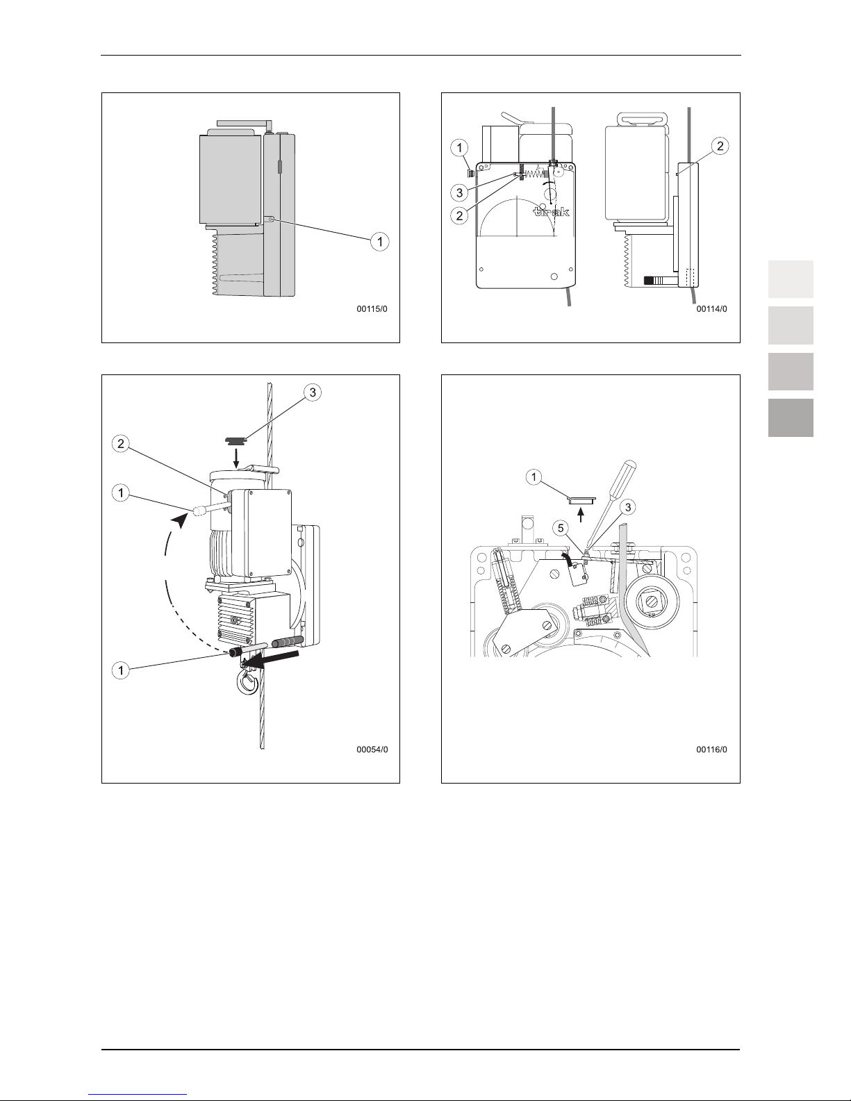
10.3 Emergency descent
The load lifting equipment can be lowered manually in the event
of a power failure.
DANGER!
Risk of being injured by falling objects!
The centrifugal brake might not brake the load in case of
overloading!
– In the event of overloading, never open the service brake
(spring-applied brake) manually.
See Fig. 15.
The centrifugal brake prevents rope speeds that are too high
when lowering manually.
For an emergency descent with low loads, increase the weight
using ballast and / or carefully pulling on the rope.
– Remove the lever (1) from the anchoring.
– Insert the lever (1) into the brake bracket through the slot in
the hood of the motor (2).
– Lift and hold the lever. The load is lowered.
– Let go of the lever to brake.
– Anchor the lever again after use.
10.4 Switching off when overloaded
Hoists with a mechanical or electrical load limiting device:
When delivered, the load limiting device has been set in such a
way that it deactivates the hoist at the latest once the load
reaches 1.25 times the load bearing capacity. A warning signal
sounds when deactivating.
Jamming of the load lifting equipment may also lead to deactivation.
When overloaded:
– Lower or release the hoist until the load has reached the
ground.
– Reduce the load until no overload is present.
When jammed:
– Lower or release the hoist until the load hangs freely again.
– Remove the obstacle before lifting the load again.
11 Foreseeable misuse
Guarantee and liability claims for personal injuries and equipment damage will be rejected if they can be traced back to one or
more of the following causes:
Unauthorized use of the device, the accessories or the
carrying means belonging to the device
Lifting personnel
Operating with a soiled rope
Operating without limit switch (hoist for lifting)
Not adhering to the stipulated maintenance periods
Cleaning with a high-pressure cleaner
Incorrect hoist installation, commissioning, operation, main-
tenance or repairs
Poor monitoring of the parts and the accessories, which has
resulted in wear occurring
Carrying out incorrect and unauthorised repairs
Use of non-original spare parts
Alteration of safety device settings
Ignoring measurements and checks that would detect early
signs of damage
Device overloaded
Load striking directly the towing rope or suspension cable
Accidents caused by foreign bodies or acts of God
The manufacturer will not accept any liability for damages
resulting from modifications and conversions made to the
devices, or from the use of non-original parts that have not
been authorised by the manufacturer. Faulty or damaged
hoists, ropes, rigging or power supply and control cables
must never be used!
12 Dismantling
DANGER!
Risk of injury through stabs and cuts!
Broken wires in the wire rope can result in protruding wires!
Protruding wires can cut or stab through safety gloves!
– Wear suitable leather protective gloves when working
with wire ropes.
– Never let the wire rope run through your hands!
– Lower the load lifting equipment and remove if necessary.
– X-Model series:
Press the DOWN button and pull the rope upwards out of
the hoist.
– T-Model series:
Press the UP or DOWN button and pull the rope out of the
hoist.
DANGER!
Danger of death due to electric shock!
– Disconnect the hoist from the power supply by pulling out
the plug.
– Pull out the power plug.
– Roll-up the rope correctly so that no loops in the rope occur
that make the rope unusable.
– Loosen the anchorage of the hoist.
– Dismantle the deflection rollers and load bearing points.
Page 25
Installation and operating manual
G932.1 - 06/2010 EN-15
ENEN
13 Shutting down
13.1 Work breaks
The hoist must be secured in the following way during work
breaks:
– Put the load lifting equipment on the ground or cordon off
the area beneath the suspended load.
– Interrupt the power supply and secure the hoist against
unauthorised use.
13.2 Temporary shutdown
If the hoist is not required for several days or weeks but should
remain mounted in the same position and location, the hoist must
be secured as follows:
– Put the load lifting equipment on the ground or cordon off
the area beneath the suspended load.
– Secure the load lifting equipment against oscillating move-
ments (e.g. tie to building).
– Pull up the rope without load to a position out of the reach of
people.
– Interrupt the power supply and secure the hoist against
unauthorised use.
13.3 Permanently decommissioning
– Dismantle the hoist and accessories, see ' 12 Dismantling'
on page 14.
– Clean the outside of the device and store.
14 Transport and storage
14.1 Hoists
Transport
Prevent the hoist from being damaged while it is being transported.
On-site, the hoist can be transported using the carrying handle,
see Fig. 1. If necessary transport with the help of a second person.
Heavy hoists can be transported using suitable transport equipment on the eye bolts or ring nuts.
Utilise the transport box when transporting with a vehicle. Secure
the hoist or the transport box with lashing straps.
Storage
Store in a dry, dust-free location that has a constant ambient
temperature.
14.2 Rope
Transport
– Protect the ropes against direct sunlight, chemicals, soiling
and mechanical damage.
– Transport the ropes on the reels whenever possible.
– Use suitable auxiliary equipment when transporting the reels.
– Rolled-up ropes without reels should be lifted and trans-
ported using a lifting strap.
– Minimise the load resulting from the dead weight as much
as possible.
Storage
– Store lightly oiled, free of dust and in a dry location.
– Avoid contact with chemicals (e.g. battery acid).
– Store without applying mechanical crushing, pressure or
tensile stress.
15 Maintenance work
15.1 Authorized maintenance personnel
DANGER!
Risk of falling! Risk of being injured by falling objects!
Mortal danger due to incorrectly performed maintenance and
service work!
Maintenance and service work which require the hoist to be
opened may only be performed by the following authorised
parties:
– Greifzug Hebezeugbau GmbH
– Lifting equipment service companies authorised by
Greifzug Hebezeugbau GmbH
– Service personnel trained and certified by Greifzug He-
bezeugbau GmbH
15.2 Mandatory inspections
A written certificate is required for the annual inspection and any
exceptional tests. The inspections must be recorded in the logbook included with delivery.
Prior to every use
Always check to ensure that the device is in an orderly working
condition before use, see ' 9.4 Commissioning' on page 12.
Annual safety inspection
The safety inspection must be carried out annually.
The safety inspection may only be undertaken by authorised
maintenance personnel, see ' 15.1 Authorized maintenance per-
Page 26
Installation and operating manual
EN-16 G932.1 - 06/2010
ENEN
sonnel' on page 15. Depending on the usage conditions (e.g.
operation in an extremely dirty environment), an intermediate
inspection may be necessary.
The general overhaul periods are, at the latest:
250 running hours for devices with 12 or 18 m/min rope
speeds,
500 running hours for devices with 6 or 9 m/min rope
speeds.
A general overhaul of the hoist must only to be undertaken by
Greifzug Hebezeugbau GmbH or a hoisting gear workshop that
has been approved by Greifzug Hebezeugbau GmbH.
We recommend that the system is tested in our factory by
Greifzug Hebezeugbau GmbH.
Contact Greifzug Hebezeugbau GmbH or your supplier with
regards to this test.
15.3 Reading the running hours counter
The running hours counter is located in the hoist's terminal box.
The running hours counter counts the time in which the hoist is in
operation as running hours (UPWARD or DOWNWARD movements).
DANGER!
Danger of death due to electric shock!
– Disconnect the hoist from the power supply by pulling out
the plug.
– Pull out the power plug.
– Open the terminal box.
– Read the running hours counter:
– Note the running hours in the logbook.
– Close the terminal box.
15.4 Care and maintenance
Interval Work Implementation
Daily
– Check the anchorage of the
hoist
– Inspect the rope for clinging
dirt
Operating personnel
– Check the rope, see page 16
Operating personnel
Weekly
– Check the connecting cable
and control cable
Operator
Interval Work Implementation
Every 50
running
hours
– Traction sheave external
teeth (only model series
X 3050), see page 17
Operating personnel
1 x annually
– Safety inspection for the
hoist
Authorized maintenance personnel
2501) / 5002)
Running
hours
– General overhaul of the hoist
Greifzug Hebezeugbau GmbH
or a hoisting gear
workshop that has
been approved by
Greifzug Hebezeugbau GmbH
Whenever
necessary
See page 16:
– Clean the rope
– Lubricate the rope
– Replace the rope
Trained person
nominated by the
operator
Whenever
necessary
– Replace the cable
Electrician
1)
Devices with 12 or 18 m/min rope speed
2)
Devices with 6 or 9 m/min rope speed
Rope
DANGER!
Risk of injury through stabs and cuts!
Broken wires in the wire rope can result in protruding wires!
Protruding wires can cut or stab through safety gloves!
– Wear suitable leather protective gloves when working
with wire ropes.
– Never let the wire rope run through your hands!
Cleaning
Brush the dirt off soiled ropes when dry if necessary. Re-lubricate
as necessary.
Use the brush attachments to clean the rope at the hoist in an
extremely dirty environment.
Lubrication
DANGER!
Danger due to falling objects due to slippery or damaged
ropes or brake failure and malfunction!
Might result in severe injuries or even death!
– Do not lubricate the rope using a lubricant that contains
disulfide (e.g. Molycote
®
).
Page 27
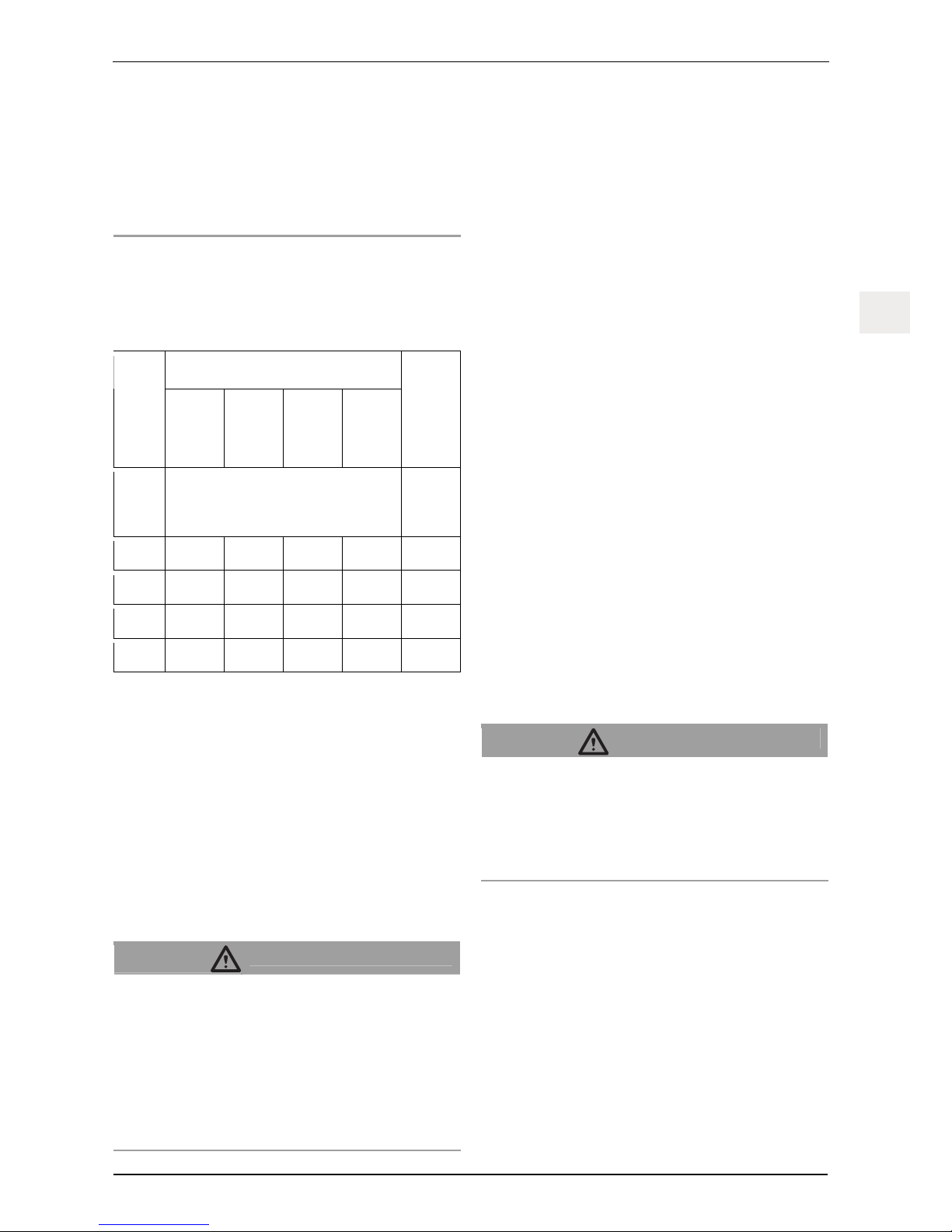
Installation and operating manual
G932.1 - 06/2010 EN-17
ENEN
– Use multi-purpose grease or oil.
– Cleaning the wire rope, the hoist or independent secon-
dary brakes with high pressure cleaners is prohibited!
Moisture results in malfunctions and damage to the motor, brake and the electrical equipment.
– Dirt on the wire rope will result in premature wear or the
corrosion of the wire rope, rigging and hoist.
Replacement
Replace the ropes immediately if the withdrawal criteria in accor-
dance with Table 5 have been reached (as per ISO 4309 and
DIN 15020, Sheet 2) or typical rope defects are present, see
Fig. 12.
Design of the rope
Nominal diameter
of the rope
Rotation-
resistant
4 x 26 5 x 19 5 x 26
Minimum permitted
rope diameter
[mm] Number of visible broken wires in the outer
strands over a length of 30 x rope's nominal
diameter.
[mm]
8 10
8 11 7,5
9 10 10 8
8,5
10 8
11 9,3
14 10
11 13,1
Table 5
Implementation: See ' 12 Dismantling' on page 14 and ' 9.3 Assembly'
on page 10.
Renewing rope tips
Send the rope to Greifzug Hebezeugbau GmbH or an lifting
equipment service company authorised by Greifzug Hebezeugbau GmbH and have the tip replaced.
Power supply and control cables
The cables must be replaced by an electrician if any damage has
been caused to the insulation or the cable connectors.
Hoists
DANGER!
Danger due to falling objects due to slippery or damaged
ropes or brake failure and malfunction!
Might result in severe injuries or even death!
– Cleaning the wire rope, the hoist or independent secon-
dary brakes with high pressure cleaners is prohibited!
Moisture results in malfunctions and damage to the motor, brake and the electrical equipment.
– Dirt on the wire rope will result in premature wear or the
corrosion of the wire rope, rigging and hoist.
See the separate maintenance instructions provided for trained
personnel.
Motor, gearbox and brake
The motor, gearbox and brake are maintenance free.
– Clean the outside if heavily soiled.
– Keep the brake free of oil and grease.
Traction sheave external teeth
(model series X 3050)
Specification of grease, see ' 4.4 Operating fluids' on page 7.
– Apply the grease gun to the lubrication nipple (1), see
Fig. 14.
– Lubricate the lubrication nipple with 3 – 5 pumps (approx.
5 cm
3
).
– Let the hoist run for approximately two seconds in the UP-
WARD and DOWNWARD directions.
– Lubricate the lubrication nipple with 3 – 5 pumps (approx.
5 cm
3
).
15.5 Adjustment
Adjust the mechanical load limiting device
X-Model series:
From 1,000 kg load bearing capacity
Up to 1,000 kg load bearing capacity optional scope of
delivery
DANGER!
Risk of being injured by falling objects!
Might result in severe injuries or even death!
– The load limiting device may only be implemented by
personnel authorised by the system manufacturer or
Greifzug Hebezeugbau GmbH.
– Observe the details in this instruction manual.
When delivered, the load limiting device has been set in such a
way that it deactivates the hoist at the latest once the load
reaches 1.25 times the load bearing capacity.
The minimum value to which the load limiting device can be set
is 10 % below the load bearing capacity of the hoist.
In order to set the load limiting device an overload is lifted. The
overload is:
Overload = Nominal load + 25%
– Only load load lifting equipment with the calculated overload.
Page 28

Installation and operating manual
EN-18 G932.1 - 06/2010
ENEN
Model series X 1020 to X 1530
See Fig. 16.
– Remove the blanking plug (1).
– Loosen the brass screw (2).
– Insert an 8 mm, 150 mm-long Allen key into the setting
screw (3).
– Loosen the setting screw (3).
The load limiting device must not react when lifting the load.
– Raise until the load lifting equipment hangs freely.
Note:
If the load limiting device reacts:
– Lower the load lifting equipment.
– Loosen the setting screw (3).
– Raise until the load lifting equipment hangs freely.
– Tighten the setting screw (3) until the load limiting device
reacts.
– Tighten the brass screw (2).
– Lower the overload to the ground.
– Raise the overload again.
The load limiting device must react. Otherwise repeat the
procedure.
– Replace the blanking plugs (1) and secure with red sealing
wax.
Type series X 3050
See Fig. 17.
– Remove the blanking plug (1).
– Loosen the lock nut (5) with the socket wrench.
– Loosen the setting screw (3).
The load limiting device must not react when lifting the load.
– Raise until the load lifting equipment hangs freely.
Note:
If the load limiting device reacts:
– Lower the load lifting equipment.
– Loosen the setting screw (3).
– Raise until the load lifting equipment hangs freely.
– Tighten the setting screw (3) until the load limiting device
reacts.
– Tighten the lock nut (5) with the socket wrench.
– Lower the overload to the ground.
– Raise the overload again.
The load limiting device must react. Otherwise repeat the
procedure.
– Replace the blanking plugs (1) and secure with red sealing
wax.
Adjust the electric load limiting device (optional)
X-Model series:
Up to 1,000 kg load bearing capacity optional scope of
delivery
DANGER!
Danger of death due to electric shock!
– Disconnect the power supply to the hoist by disconnect-
ing the connector before opening the terminal box.
– Do not touch any conducting parts when performing the
adjustment.
– Cover conducting parts if necessary.
Risk of being injured by falling objects!
Might result in severe injuries or even death!
– The load limiting device may only be implemented by
personnel authorised by the system manufacturer or
Greifzug Hebezeugbau GmbH.
– Observe the details in this instruction manual.
When delivered, the load limiting device has been set in such a
way that it deactivates the hoist at the latest once the load
reaches 1.25 times the load bearing capacity.
In order to set the load limiting device an overload is lifted. The
overload is:
Overload = Nominal load + 25%
The electronic load limiting device reacts to the power consumption of the motor. Hoists with two speeds are equipped with two
electric load limiting devices. The adjustment must be made for
both load limiting devices and speeds. The overload is recognised when lifting.
A lower limiting value, e. g. due to a lower load bearing capacity
of the components which the hoist or the deflection roller are
attached to, can only be set by authorised maintenance personnel.
Default setting
See Fig. 18.
– Remove the sealing wax on the controllers (1) and (2).
– Turn the upper controller (1) for the rated power to the right
to the limit.
– Turn the lower controller (2) for the start monitoring to the
right to the limit.
Adjusting the overload
– Only load load lifting equipment with the calculated overload.
– While lifting the excessive load turn the upper controller (1)
to the left until the hoist stops.
– Lower the excessive load until the rope is unloaded.
– Raise the excessive load again:
The hoist must stop as soon as it comes under load.
Page 29
Installation and operating manual
G932.1 - 06/2010 EN-19
ENEN
Adjusting the start override
– Load the load raising equipment with the nominal load.
– Raise the nominal load from the ground.
– Turn the lower controller (2) to the left to the limit.
– Press the UP button.
The hoist must stop immediately.
Note:
Briefly press the DOWN button every time after stopping the
hoist during this setting procedure in order to re-enable the raising movement.
– Turn the lower controller (2) slightly to the right.
– Press the UP button.
– Repeat the procedure until it becomes possible to raise the
nominal load.
– Seal both controllers with sealing wax.
15.6 Ordering spare parts
Spare parts lists can be requested from your supplier or directly
from Greifzug Hebezeugbau GmbH.
The necessary information for placing the order is located on the
nameplates of the individual components, see Fig. 10. Replace
missing or illegible labels immediately.
Rope drive:
Article no., tirak™ model, rope diameter, serial number
Motor:
Article no., Motor model
Brakes:
Article no., Type and coil voltage of the brake
Electrical controls:
Number of the circuit diagram
16 Disposal and environmental
protection
The equipment is made from recyclable materials. If the equipment is later scrapped, it must be disposed off correctly. The
national versions of the waste legislation directive 75/442/EEC
apply within the European Union (in Germany Kreislaufwirtschafts- und Abfallgesetz (KrWAbfG)).
The manufacturer is obliged to take back and dispose of specific
electrical and electronic components in accordance with Directive
2002/96/EC. The following symbol is used on the nameplate of
such components to identify them:
Page 30

Installation and operating manual
EN-20 G932.1 - 06/2010
ENEN
17 Troubleshooting
DANGER!
Risk of being injured by falling objects!
The load lifting equipment may tip over if it jams!
– Stop the hoist immediately.
– Determine the cause and eliminate the fault.
Fault
Cause Clearing
The motor starts but the rope does not move.
Rope jam in the hoist due to damaged or incorrect rope.
Obstructed rope exit.
– Support the load (e.g. with a wedge clamp or lever hoist).
– Cut the rope in front of and behind the hoist.
– Send the hoist to be repaired.
– When available, install a new rope in replacement hoist.
The load has jammed or is tied in place.
– Carefully free or untie the load.
– Check the rope, rigging and load lifting equipment for their operating
safety.
Hoist does not work
Control unit not switched on.
– Switch on control unit.
EMERGENCY OFF button pressed.
– Unlock EMERGENCY OFF button.
Disconnected mains supply.
– Clarify the cause and eliminate the fault.
Power supply cable between the mains connection and the control unit
disconnected.
– Check all cables and connections and repair as necessary.
Power supply connected incorrectly or the neutral conductor is missing.
– Have the connection repaired by an electrician.
– If necessary, have it modified by the manufacturer.
Protective cut-out tripped after overheating due to insufficient motor
cooling.
– Clean motor cover.
Protective cut-out tripped due to overheating caused by the voltage being
too high or too low.
– Have an electrician measure the voltage and power consumption
when subjected to load.
– Increase the wire cross-section if necessary.
Where applicable, two poles in the power supply cable are switched. The
built-in reverse polarity protection locks out the control unit.
– Turn the phase reverser in the plug by 180°, see Fig. 19.
The brake does not open (no click when switching on / off) because the
power supply, brake coil, or rectifier are defective.
– Have the power supply, brake coil and rectifier checked by an
electrician and repair or replace.
Page 31

Installation and operating manual
G932.1 - 06/2010 EN-21
ENEN
Fault
Cause Clearing
Hoist does not work
The brake does not open (no click when switching on / off) because the
brake rotor is worn.
– Send the hoist to the manufacturer for repairs or hand over to a
specialist hoist workshop.
The load cannot be lifted / pulled although the rope can be lowered / slackened.
The load has jammed on an obstacle.
– Carefully move the load downwards and remove the obstacle.
– Check the rope, rigging and lifting equipment to confirm their operat-
ing safety.
Overload
– Check the load and reduce if necessary.
– Reeve the rope according to the block and tackle principle, see
Fig. 8.
The rope has run out completely after lowering or slackening without load.
– Feed the rope back in.
– Clarify the cause.
– Avoid repeating, e.g. by using a longer rope.
Fault in the UP control circuit of the hoist.
– Have the connections, wiring and cut-outs checked by an electrician
and repair if necessary.
Limit switch faulty or tripped.
– Move down until the limit switch is free.
– Check the limit switch and replace if necessary.
Poor motor performance due to a defective starter capacitor.
– Have the starter capacitor checked by an electrician and replace if
necessary.
Defective centrifugal switch (starter capacitor overloaded).
– Measure the current on the auxiliary winding in the terminal box.
Repairs should only be carried out by Greifzug Hebezeugbau
GmbH.
The motor hums intensively or the rope drive creaks although UP and DOWN travel is possible.
Overheating caused by poor motor cooling.
– Clean motor cover.
Overheating due to the voltage being too high or too low.
– Have an electrician measure the voltage and power consumption
when subjected to load.
– Increase the wire cross-section if necessary.
ATTENTION! Dirt in the rope drive.
Rope and rope drive might be damaged.
– Replace the hoist as soon as possible and have the hoist checked /
repaired by Greifzug Hebezeugbau GmbH or an authorised hoisting
gear workshop.
Page 32

Installation and operating manual
EN-22 G932.1 - 06/2010
ENEN
Fault
Cause Clearing
The load cannot be lowered / slackened although the rope can be lifted / pulled.
The load has come to rest on an obstacle or has jammed on an obstacle.
– Carefully move the load upwards and remove the obstacle.
– Check the rope, rigging and lifting equipment to confirm their operat-
ing safety.
Fault in the DOWN control circuit of the hoist.
– Trigger emergency descent by releasing the brake, see
' 10.3 Emergency descent' on page 14.
– Have the connections, wiring and cut-outs checked by an electrician
and repair if necessary.
The rope cannot be fed in.
Rope tip faulty.
– Renewing rope tips, see ' 15.4 Care and maintenance, Rope' on
page 16.
Page 33

Installation and operating manual
G932.1 - 06/2010 EN-23
ENEN
18 EU Declaration of Conformity (Extract)
The manufacturer hereby declares
Greifzug Hebezeugbau GmbH
Scheidtbachstraße 19–21 51469 Bergisch Gladbach
represented by
Dr. Ing. Uwe Schuht
Managing Director
DECLARATION OF CONFORMITY
that the machine described complies with technological safety standards that were applicable to the equipment in the EUROPEAN
UNION when it was launched on the market by the manufacturer.
APPLICABLE DIRECTIVES AND STANDARDS:
2006/42/EC; 2006/95/EC; 2004/108/EC
EN 14492-1; EN ISO 12100-1; EN ISO 12100-2; EN ISO 14121-1; EN ISO 13849-1; EN 60204
DESIGNATION
Rope traction hoist
APPLICATION
Transport of material
MODEL
X 300, X 400, X 500, X 800, X 1020, X 1530, X 3050, T 1000, T 1020
SERIAL NUMBER
Year of manufacture
from 01.2010
Responsible for the documentation:
Dr. Ing. Uwe Schuht, Tel.: +49 (0) 2202 1004 63
Bergisch Gladbach, date
Page 34

Installation and operating manual
EN-24 G932.1 - 06/2010
ENEN
Page 35

Montage- und Betriebsanleitung
G932.1 - 06/2010 DE-1
DE
Inhaltsverzeichnis
1 Allgemeines........................................................................ 2
1.1 Verwendete Begriffe und Abkürzungen .................... 2
1.2 Verwendete Symbole................................................ 3
2 Sicherheit ........................................................................... 3
2.1 Allgemeine Sicherheitshinweise ............................... 3
2.2 Hinweise für den Betreiber........................................ 4
3 Übersicht ............................................................................ 4
3.1 Lieferzustand ............................................................ 4
3.2 Lieferumfang............................................................. 4
3.3 Gerätebeschreibung ................................................. 5
4 Beschreibung..................................................................... 6
4.1 Funktionsbeschreibung............................................. 6
4.2 Komponenten/Baugruppen....................................... 6
4.3 Technische Daten..................................................... 7
4.4 Betriebsmittel ............................................................ 7
4.5 Stromlaufplan............................................................ 7
4.6 Bedieneinheit ............................................................ 7
4.7 Sicherheitseinrichtungen........................................... 8
4.8 Befestigung............................................................... 8
4.9 Erhöhen der Tragfähigkeit ........................................ 8
5 Seile .................................................................................... 8
6 Optionales Zubehör........................................................... 9
7 Optionen............................................................................. 9
8 Notwendiges Zubehör....................................................... 9
9 Installation und Inbetriebnahme ...................................... 9
9.1 Richtlinien und Normen............................................. 9
9.2 Prüfungen vor Beginn der Montage.......................... 9
9.3 Montage.................................................................. 10
9.4 Inbetriebnahme....................................................... 12
10 Bedienung/Betrieb........................................................... 13
10.1 Prüfungen vor Arbeitsbeginn .................................. 13
10.2 Betrieb..................................................................... 13
10.3 Not-Ablass .............................................................. 14
10.4 Abschaltung bei Überlast........................................ 14
11 Vorhersehbarer Missbrauch........................................... 14
12 Demontage ....................................................................... 15
13 Außer Betrieb setzen....................................................... 15
13.1 Arbeitsunterbrechung.............................................. 15
13.2 Vorübergehend Stillsetzen...................................... 15
13.3 Dauerhaft außer Betrieb setzen.............................. 15
14 Transport und Lagerung..................................................15
14.1 Winde.......................................................................15
14.2 Seil...........................................................................16
15 Instandhaltung..................................................................16
15.1 Autorisiertes Wartungspersonal...............................16
15.2 Erforderliche Prüfungen...........................................16
15.3 Ablesen des Betriebsstundenzählers ......................16
15.4 Pflege und Wartung.................................................16
15.5 Einstellarbeiten........................................................18
15.6 Ersatzteile bestellen.................................................19
16 Entsorgung und Umweltschutz.......................................20
17 Fehlersuche / Störungsbeseitigung ...............................21
18 EG-Konformitätserklärung (Auszug)..............................24
GEFAHR!
Verletzungsgefahr durch herabfallende Gegenstände,
Fehlfunktionen, falsche Nutzung und Fehlbedienung!
Beachten Sie diese Anleitung nicht:
können schwerste Verletzungen und der Tod die Folge sein,
können Schäden am Gerät entstehen.
– Lesen Sie diese Anleitung sorgfältig durch, bevor Sie
dieses Gerät montieren und in Betrieb nehmen.
– Beachten Sie die Hinweise und Verhaltensregeln, die für
einen sicheren Betrieb des Geräts notwendig sind.
Page 36

Montage- und Betriebsanleitung
DE-2 G932.1 - 06/2010
DE
1 Allgemeines
Ausgabedatum
Juni 2010
Urheberrecht
Das Urheberrecht an dieser Anleitung verbleibt bei der Greifzug
Hebezeugbau GmbH.
Diese Anleitung ist nur für den Betreiber der darin beschriebenen
Anlagen sowie dessen Personal bestimmt. Diese Anleitung muss
dem Bediener jederzeit zugänglich sein. Weitere Exemplare
können angefordert werden.
Ohne Zustimmung der Greifzug Hebezeugbau GmbH dürfen
keine Bestandteile dieser Anleitung vervielfältigt, verbreitet oder
anderweitig mitgeteilt werden.
Zuwiderhandlungen können strafrechtliche Folgen haben.
Anschrift des Herstellers
Verkaufs- und Servicestelle:
Greifzug Hebezeugbau GmbH
Scheidtbachstraße 19-21
51469 Bergisch Gladbach, Deutschland
Postfach 20 04 40
51434 Bergisch Gladbach, Deutschland
Telefon: +49 (0) 22 02 / 10 04-0
Telefax: +49 (0) 22 02 / 10 04-50 + 70
Die Greifzug Hebezeugbau GmbH behält sich das Recht vor, im
Zuge der Produktverbesserung jegliche Änderungen an dem in
dieser Anleitung beschriebenen Produkt vorzunehmen.
Kunden können über die Unternehmen der TRACTEL-Gruppe
und die von der TRACTEL-Gruppe autorisierten Instandhalter auf
Anfrage Dokumentationen über andere TRACTEL-Produkte
erhalten: Hebezeuge und deren Zubehör, fest installierte oder
mobile Arbeitsbühnen zur Innen- und Außenbefahrung von Gebäuden, Anschlagmittel, Abfangsicherungen für Lasten, Persönliche Schutzausrüstung gegen Absturz, Zugkraft- und Seilspannungsmessgeräte, etc. Besuchen Sie hierfür auch die
TRACTEL–Website www.tractel.com.
Die TRACTEL-Gruppe und ihr Händlernetzwerk bieten Ihnen bei
Bedarf zusätzlich Kunden- und Reparaturservice.
1.1 Verwendete Begriffe und Abkürzungen
In dieser Anleitung haben die folgenden Begriffe diese Bedeutung:
Anlage / Maschine
Im Sinne der Maschinenrichtlinie 2006/42/EG gelten Lastaufnahmemittel, Hebezeuge und Anschlagmittel zum Heben als
Maschine. Mit Anlage oder auch Maschine wird die Einrichtung
bezeichnet, in die die hier beschriebene Maschine eingebaut
wird.
Anlagenhersteller
Der Anlagenhersteller (Anlagenplaner, Anlagenhersteller, Montagebetrieb) ist der Inverkehrbringer der Anlage und aller notwendigen Komponenten. Der Anlagenhersteller ist für den Entwurf, die Herstellung, den Einbau und das Inverkehrbringen
verantwortlich.
Anschlagmittel
Anschlagmittel sind nicht zum Hebezeug gehörende Einrichtungen, die eine Verbindung zwischen Tragmittel und Last oder
Tragmittel und Lastaufnahmemittel herstellen (z. B. Seilschlaufen,
Rundschlingen, Schäkel, Wirbelhaken, Ösenhaken, Umlenkrollen).
Anschlagpunkt, Aufhängepunkt
Teil der bauseitigen Aufhängekonstruktion, an dem Tragseil,
Sicherheitsseil, Umlenkrollen oder das Hebezeug angeschlagen
werden.
Bediener
Person, die vom Betreiber in die Bedienung des Produktes eingewiesen und mit dem Gebrauch betraut ist.
Betreiber
Der Betreiber ist für den ordnungsgemäßen Betrieb der Anlage/des Geräts sowie für die Einhaltung der Wartungsintervalle
und die Durchführung der Instandsetzungsarbeiten verantwortlich.
Elektrofachkraft
Elektrofachkraft ist, wer über ausreichende Kenntnisse verfügt
oder durch eine Ausbildung die notwendigen Qualifikationen
erworben hat, Risiken zu erkennen und Gefährdungen zu vermeiden, die von der Elektrizität ausgehen können.
Fangvorrichtung
Vorrichtung zum Abfangen von Lastaufnahmemitteln bei Tragseilbruch oder Störungen, z. B. Versagen des Antriebs der Winde.
Hebezeug / Maschine zum Heben von Lasten
Gerät oder Einrichtung bestehend aus einem Gerät mit Tragmitteln zum Heben oder Transportieren von Lasten (z. B. Seilwinde
oder Seilwinde mit Seil und Wirbelhaken).
Kunde/Endkunde
Der Kunde oder Endkunde ist der Kunde des Anlagenherstellers
und kann gleichzeitig auch der Betreiber sein.
Lastaufnahmemittel (LAM)
Ein nicht zum Hebezeug gehörendes Bauteil oder Ausrüstungsteil, dass das Ergreifen der Last ermöglicht und das zwischen
Maschine und Last oder an der Last selbst angebracht wird oder
das dazu bestimmt ist, ein integraler Bestandteil der Last zu
werden. Als Lastaufnahmemittel gelten auch Anschlagmittel und
ihre Bestandteile.
Materialaufnahmemittel (MAM)
Lastaufnahmemittel für Material.
Page 37

Montage- und Betriebsanleitung
G932.1 - 06/2010 DE-3
DE
Nennlast
Die Nennlast entspricht der Tragfähigkeit der Winde und ist die
Last, die an einer bestimmten Stelle, z. B. an einer Umlenkrolle,
einwirkt. Durch einfaches Einscheren verdoppelt sich die Nennlast.
Sachkundige Person
Eine benannte und entsprechend ausgebildete Person, die durch
ihre Kenntnisse und praktischen Erfahrungen in der Lage ist, mit
den benötigten Anweisungen versehen, die erforderlichen Arbeiten sicher auszuführen.
tirak™
Im Text wird tirak™ als Kurzbezeichnung für die Winde verwendet.
Tragfähigkeit
Die Tragfähigkeit gibt an, welche Last die Winde maximal heben
oder ziehen darf. Die Tragfähigkeit kann durch Einscheren des
Seils vervielfacht werden.
Tragmittel
Ein Tragmittel ist eine mit dem Hebezeug verbundene Einrichtung zur Aufnahme von Lastaufnahmemitteln, Anschlagmitteln
oder Lasten (z. B. ein mit dem Tragseil fest verbundener Haken).
Wartungspersonal
Eine benannte und von der Greifzug Hebezeugbau GmbH geschulte Person mit gültigem Zertifikat, die in der Lage ist, mit den
benötigten Anweisungen versehen, die erforderlichen Wartungs-,
Prüf- und Instandsetzungsarbeiten sicher auszuführen.
1.2 Verwendete Symbole
GEFAHR!
Art und Quelle der Gefahr.
Folge: z. B. Tod oder schwere Verletzungen.
– Maßnahmen, mit denen die Gefahr vermieden wird.
ACHTUNG!
Art und Quelle der Gefahr.
Folge: z. B. Sachschäden oder Umweltschäden.
– Maßnahmen, mit denen Schäden vermieden werden.
Hinweis:
Dieses Symbol kennzeichnet keine Sicherheitshinweise, sondern
gibt Informationen zum besseren Verständnis der Abläufe.
2 Sicherheit
2.1 Allgemeine Sicherheitshinweise
GEFAHR!
Gefahr von schweren Unfällen durch Fehlfunktionen,
falsche Nutzung und Fehlbedienung!
– Beachten Sie folgende Angaben, damit der sichere
Betrieb und die ordnungsgemäße Funktion des Gerätes gewährleistet sind!
– Beachten Sie auch die speziellen Sicherheitshinweise
für alle auszuführenden Arbeiten in den einzelnen Kapiteln dieser Anleitung.
– Fehlerhafte oder beschädigte Winden, Seile, Anschlagmittel
oder Zuleitungs- und Steuerkabel dürfen nicht eingesetzt
werden.
– Die Winden dürfen nur mit einem Original-tirak™-Drahtseil
mit dem angegebenen Seildurchmesser verwendet werden.
– Seil, Winde und Anschlagmittel dürfen nicht mit stark ver-
schmutzenden Baumitteln, wie z. B. Beton, Epoxidharz oder
sonstigen haftenden Arbeitsmitteln verunreinigt werden.
Schützen Sie die Bauteile vor Verunreinigungen! In stark
verschmutzter Umgebung Bürstenvorsätze für die Seilreinigung verwenden.
– Beachten Sie die Ablegereife des Seils, siehe ' 15.4 Pflege
und Wartung, Seil' auf Seite 17.
– Das Reinigen des Seils oder der Winde mit einem Hoch-
druckreiniger ist verboten! Eindringende Feuchtigkeit führt
zu Fehlfunktionen und Schäden an Motor, Bremse und der
elektrischen Ausrüstung.
– Schmutz am Seil führt zum vorzeitigen Verschleiß oder zur
Zerstörung von Seil, Anschlagmittel und Winde.
– Beachten Sie die Hinweise für Transport, Lagerung und
Reinigung ab Seite 15.
– Beachten Sie die Sicherheitsdatenblätter für die verwende-
ten Schmierstoffe des jeweiligen Herstellers.
– Befestigungsmittel müssen den Angaben in dieser Anleitung
bzw. den gültigen Normen/Richtlinien entsprechen.
– Die zulässige Tragfähigkeit darf nicht überschritten werden.
– Motoren können während des Betriebes heiß werden. Moto-
ren nicht berühren.
– Der Betrieb ohne Gummistopfen am Motor (Position 3,
siehe Abb. 15) ist verboten. Eindringende Feuchtigkeit kann
die Wirkung der Bremse beinträchtigen. An der freiliegen-
den Motorwelle besteht Verletzungsgefahr.
– Bei Gewitter und Sturm ist der Betrieb im Freien verboten.
Es besteht Gefahr durch Blitzschlag oder Kippen der Last
durch Windböen.
– Bereits bei der Arbeitsplanung sind die örtlichen Klima- und
Windverhältnisse zu berücksichtigen: Im Zweifelsfall vor Ar-
beitsbeginn die zu erwartenden Wetter- und Windbedingun-
gen beim Wetteramt anfragen.
Page 38

Montage- und Betriebsanleitung
DE-4 G932.1 - 06/2010
DE
– Instandsetzungs- und Wartungsarbeiten dürfen nur von
autorisiertem Wartungspersonal durchgeführt werden, siehe
' 15.1 Autorisiertes Wartungspersonal' auf Seite 16.
– Montage und Bedienung dürfen nur durch geschultes und
eingewiesenes Personal unter Berücksichtigung dieser Anleitung erfolgen.
– Private Anwender sind verpflichtet, sich durch die Greifzug
Hebezeugbau GmbH in der Montage, der Bedienung und
der Wartung des Geräts schulen zu lassen.
– Arbeiten an elektrischen Ausrüstungen dürfen nur von einer
Elektrofachkraft oder von unterwiesenen Personen unter
Leitung und Aufsicht einer Elektrofachkraft gemäß den
elektrotechnischen Normen, Vorschriften und Regeln vorgenommen werden.
– Nicht unter schwebenden Lasten aufhalten. Wenn nötig,
Gefahrenbereich absperren.
– Während des Betriebs nicht an das Seil greifen.
– Während des Betriebs nicht an den Ein- oder Auslauf der
Winde greifen. Es besteht Einzugs- und Quetschgefahr.
– Abhängig von der Einbausituation der Winde kann das
Tragen eines Gehörschutzes notwendig sein.
– Wenn die Last bauseitig nicht geführt werden kann, muss
ein drehungsarmes Seil mit Wirbelhaken oder Seilwirbel
verwendet werden.
2.2 Hinweise für den Betreiber
– Ist mehr als eine Person mit einer der hier beschriebenen
Tätigkeiten betraut, so hat der Betreiber einen Aufsichtfüh-
renden zu bestimmen, der weisungsbefugt ist.
– Der Betreiber ist dafür verantwortlich, klare Bedienungs-,
Instandhaltungs-, Wartungs- und sonstige Betriebsanwei-
sungen bereitzustellen und durch Schulung und Anweisung
des Personals den sachgerechten und bestimmungsgemä-
ßen Betrieb und die sachgerechte Bedienung des Geräts si-
cherzustellen.
– Der Betreiber ist für den ordnungsgemäßen Betrieb der
Anlage sowie für die Einhaltung der Wartungsintervalle und
die Durchführung von Wartungsarbeiten verantwortlich.
– Der Betreiber ist verpflichtet, das mitgelieferte Logbuch zu
führen.
– Die nationalen Regelungen zum Arbeitsschutz sind zu
beachten. Innerhalb der Europäischen Union gilt die EU-
Richtlinie 89/391/EWG (in Deutschland die Betriebssicher-
heitsverordnung (BetrSichV)). Die nationalen Arbeitsschutz-
bestimmungen im Betreiberland müssen beachtet werden.
– Stellen Sie geeignete Schutzausrüstung zur Verfügung, wie
z. B. Schutzhandschuhe, Gehörschutz und Absturzsiche-
rung. Zur persönlichen Schutzausrüstung gehört auch der
Schutz gegen extreme Witterungsbedingungen (z. B. Son-
nenschutz, Kälteschutz).
– Sorgen Sie immer für eine ausreichende Beleuchtung des
Arbeitsplatzes.
– Ein Exemplar dieser Anleitung muss dem beauftragten
Personal ausgehändigt werden und jederzeit zugänglich
sein.
– Da die Greifzug Hebezeugbau GmbH den späteren Anwen-
dungsfall der hier beschriebenen Winde nicht kennt, ist der
Betreiber dazu verpflichtet, sein Personal über weitere Sicherheitshinweise sowie über ergänzende Wartungsarbeiten zu informieren.
– Für die Wahl der Befestigungsmethode und geeignete
Anschlagmöglichkeiten ist der Betreiber der Anlage verantwortlich.
– Befestigungsmittel müssen den Angaben in dieser Anleitung
bzw. den gültigen Normen/Richtlinien entsprechen.
– Bei der Verwendung anderer als der Original-Teile, insbe-
sondere eines anderen als des vorgeschriebenen Originaltirak™-Seils, entfällt der Garantieanspruch gegenüber dem
Hersteller und die CE-Kennzeichnung verliert ihre Gültigkeit.
– Beachten Sie den zulässigen Temperaturbereich, siehe
Tabelle 1 auf Seite III.
3 Übersicht
3.1 Lieferzustand
Die Winde wird komplett montiert geliefert.
3.2 Lieferumfang
Winde mit Steuer- und Anschlusskabel (fest verdrahtet)
gemäß Bestellspezifikation
tirak
TM
-Drahtseil gemäß Bestellspezifikation
Original-Montage- und Betriebsanleitung
Stromlaufplan
Logbuch
Prüfzertifikate
CE-Konformitätserklärung
Endschalter zum Abschalten von Hub- und Zugbewegungen
gemäß Bestellspezifikation
Lieferumfang optional:
Hängetaster, steckbar
Zentralsteuerung, steckbar
elektronische oder mechanische Hubkraftbegrenzung
Umlenkrolle
Bürstenvorsätze zum Reinigen des Seils
Die Längen des Steuerkabels und des Anschlusskabels werden
bei der Bestellung festgelegt. Siehe auch ' 6 Optionales Zubehör'
auf Seite 9, ' 7 Optionen' auf Seite 9 und 'Elektrischer Anschluss'
auf Seite 11.
Page 39

Montage- und Betriebsanleitung
G932.1 - 06/2010 DE-5
DE
3.3 Gerätebeschreibung
Bestimmungsgemäßer Gebrauch
Die Winden sind für das Heben und Senken sowie das Ziehen
und Nachlassen oder Verfahren von Lasten vorgesehen. Der
Transport von Personen ist verboten. Die Winde ist für den gewerblichen oder privaten Gebrauch geeignet. Der genaue Verwendungszweck wird durch den Betreiber oder den Anlagenhersteller festgelegt.
Zum Gerät gehörende Haken, Schäkel und Ösen oder sonstige
optionale Tragmittel dürfen nur in Kombination mit diesem Gerät
verwendet werden.
X-Typenreihe:
Der Einlauf des Seils ist an der Motorseite (Pfeil am Gehäuse
beachten!). Das entspricht der Lastseite der Winde. Der Auslauf
des Seils ist die lastlose Seite der Winde. Die lastlose Seite der
Winde darf mit maximal 100 kg belastet werden (z. B. durch die
Vorspannung des Seils).
T-Typenreihe:
Die Winde kann in beide Richtungen ziehen. Der Einlauf des
Seils kann abhängig von der Laufrichtung an der Motorseite oder
an der gegenüberliegenden Seite sein. Beim Ziehen darf die
Vorspannung des Seils nicht mehr als 400 kg betragen (siehe
Abb. 8 g/h).
Die Winden dürfen nur mit einem Original-tirak™-Drahtseil mit
dem angegebenen Seildurchmesser verwendet werden.
Wenn die Last bauseitig nicht geführt werden kann, muss ein
drehungsarmes Seil mit Wirbelhaken oder Seilwirbel verwendet
werden.
Instandsetzungs- und Wartungsarbeiten dürfen nur von autorisiertem Wartungspersonal durchgeführt werden, siehe
' 15.1 Autorisiertes Wartungspersonal' auf Seite 16.
Die Greifzug Hebezeugbau GmbH erklärt, dass die in dieser
Anleitung beschriebene Maschine den technischen Sicherheitsbestimmungen entspricht, die zum Zeitpunkt des Inverkehrbringens in der Europäischen Union durch den Hersteller für die
Ausrüstung gelten.
Die Inbetriebnahme der Maschine ist solange verboten, bis die
Maschine in welche diese eingebaut wird, als Ganzes den Bestimmungen der Richtlinie 2006/42/EG sowie dem entsprechenden nationalen Rechtserlass zur Umsetzung der Richtlinie in
nationales Recht entspricht und die entsprechende Konformitätserklärung ausgestellt ist.
Für Maschinen zum Heben von Lasten muss durch den Betreiber
oder Anlagenhersteller eine Risikobeurteilung gemäß Anhang I
der Richtlinie 2006/42/EG durchgeführt werden. EN 14492-1
muss bei der Anlagenplanung berücksichtigt werden.
Jede von den hier genannten Angaben abweichende Verwendung gilt als nicht bestimmungsgemäß. Für hieraus resultierende
Schäden haftet die Greifzug Hebezeugbau GmbH nicht. Das
Risiko trägt allein der Betreiber. Zur bestimmungsgemäßen
Verwendung gehört auch das Beachten aller Hinweise aus dieser Anleitung, insbesondere die Einhaltung der Montage- und
Instandhaltungsvorschriften.
Gewährleistungs- und Haftungsausschlüsse
Siehe ' 11 Vorhersehbarer Missbrauch' auf Seite 14.
Einsatzbereich
Die Winde ist für folgende Betriebsbedingungen geeignet:
Für Festeinbauten oder wechselnde Installationen
Für kurzfristigen Betrieb: Triebwerksgruppen siehe
Tabelle 1 auf Seite III.
In Höhenlagen bis maximal 1000 m über NN
Zulässiger Temperaturbereich siehe Tabelle 1 auf Seite III
GEFAHR!
Gefahr von schweren Unfällen!
– Der 24h-Betrieb ist verboten.
– Der Einsatz in explosionsgefährdeten Bereichen ist
verboten.
– Der Einsatz in korrosiver Umgebung ist verboten.
1)
– Der Einsatz in der Nähe von offenem Feuer oder in sehr
heißer Umgebung ist verboten.
– Der Personentransport ist verboten!
1)
Korrosionsschutz gemäß Bestellspezifikation
Einbaubeispiel
Siehe Abb. 8.
Bauliche Voraussetzungen
Bauliche Einrichtungen für die Befestigung der Winde müssen
mindestens die 4fache Tragfähigkeit der Winde besitzen.
Beachten Sie, dass sich abhängig von der Anordnung von Hebezeug, Umlenkrolle und Last die Belastung von Umlenkrolle,
Anschlagmittel und Befestigungspunkt erhöht! Siehe
' 4.9 Erhöhen der Tragfähigkeit auf Seite 8.
Der Fahrweg von Winden zum Heben muss mit einem oder
mehreren Endschaltern begrenzt sein, so dass die Aufwärtsfahrt
und/oder Abwärtsfahrt gestoppt wird. Der Betreiber oder Anlagenhersteller muss unter Berücksichtigung seiner Risikobeurteilung die Bauform und den Anbringungsort der Endschalter festlegen.
Der Betreiber oder Anlagenhersteller muss einen Endschalter,
ggf. einen Not-Endschalter und einen Boden-Endschalter einbauen und an der Winde anschließen. Die Endschalter müssen
zwangsöffnend sein. Der Abstand zur Seilbefestigung oder zu
hervorstehenden Bauteilen muss mindestens 1,5 m betragen.
Die Seillänge muss so gewählt werden, dass die Seilendverbindung bzw. der Lastaufnahmepunkt oder das Seilende nicht in
das Gehäuse der Winde oder in die Umlenkrolle gezogen werden können.
Wenn die Last bauseitig nicht geführt werden kann, muss ein
drehungsarmes Seil mit Wirbelhaken oder Seilwirbel verwendet
werden.
Page 40

Montage- und Betriebsanleitung
DE-6 G932.1 - 06/2010
DE
Die Bedieneinrichtung muss so positioniert werden können, dass
die gefahrlose Bedienung jederzeit möglich ist.
Seil, Winde und Anschlagmittel dürfen nicht mit stark verschmutzenden Baumitteln, wie z. B. Beton, Epoxidharz oder sonstigen
haftenden Arbeitsmitteln verunreinigt werden. Die Bauteile müssen vor Verunreinigungen geschützt werden.
Typenschilder und Hinweisschilder/Grenzen der
Anwendung
Siehe Abb. 10.
Pos. Bezeichnung
1 Hinweisschild 'Durchmesser des Drahtseils'
2 Typenschild tirak™
3 Typenschild Bremse
4 Typenschild Elektromotor
5 Hinweisschild Notablass
6 Seilkennzeichnung
Auf den Typenschildern finden Sie notwendige Informationen.
Richtlinien und Normen
Zugrundeliegende Richtlinien und Normen: siehe ' 9.1 Richtlinien
und Normen' auf Seite 9.
Produktvarianten in der Anleitung
In dieser Anleitung werden die in Tabelle 1 auf Seite III aufgeführten Produktvarianten beschrieben.
Betriebsstundenzähler
Der Betriebsstundenzähler befindet sich im Klemmkasten der
Winde. Der Betriebsstundenzähler zählt die Zeiten als Betriebsstunden, in denen die Winde in Betrieb ist (AUF- oder ABBewegung). Betriebsstundenzähler ablesen: siehe ' 15.3 Ablesen
des Betriebsstundenzählers' auf Seite 16.
4 Beschreibung
4.1 Funktionsbeschreibung
Der tirakTM ist eine Winde zur Beförderung von Lasten. Die Winde wird mit einem Elektromotor betrieben.
Die Winden der X-Typenreihe können in Zugrichtung des Seils
heben und senken, sowie ziehen und nachlassen.
Die Winden der T-Typenreihe können in beide Richtungen ziehen und werden z. B. zum Verfahren von Lasten eingesetzt.
Die Bedienung erfolgt an einem Hängetaster, einem Bedienkasten oder einer Zentralsteuerung.
Die elektromagnetische Federdruckbremse schließt automatisch,
wenn die Bedieneinrichtung für AUF- bzw. AB-Fahrt losgelassen
wird oder wenn der Strom ausfällt. Eine Fliehkraftbremse verhindert beim manuellen Ablassen der Last eine zu hohe Geschwindigkeit des Seils.
Die Tragfähigkeit der Winde kann durch Einscheren des Seils
nach dem Flaschenzugprinzip vervielfacht werden. Siehe
' 4.9 Erhöhen der Tragfähigkeit' auf Seite 8.
Durch Drücken der NOT-AUS-Taste kann die Winde in Gefahrsituationen sofort angehalten werden.
X-Typenreihe:
Winden ab 1000 kg Tragfähigkeit sind mit einer mechanischen
Hubkraftbegrenzung ausgestattet. Winden bis 1000 kg Tragfähigkeit können optional mit einer elektronischen oder mechanischen Hubkraftbegrenzung ausgestattet werden.
Die Hubkraftbegrenzung schaltet die Winde spätestens dann ab,
wenn das 1,25fache der Tragfähigkeit erreicht wird.
T-Typenreihe:
Winden der T-Typenreihe können optional mit einer elektronischen Hubkraftbegrenzung ausgestattet werden.
Die Hubkraftbegrenzung schaltet die Winde spätestens dann ab,
wenn das 1,25fache der Tragfähigkeit erreicht wird.
4.2 Komponenten/Baugruppen
Siehe Abb. 1.
Pos. Bezeichnung
1 Seil
2 Steckverbinder zum Endschalter
3 Bremslüfterhebel
4 Griff
5 Steckverbinder zur Steuerung1)
6 Klemmkasten (optional mit Betriebsstundenzähler)
7 Seiltrieb
8 Tragegriff
9 Getriebe
10 Bedieneinheit1)
Page 41

Montage- und Betriebsanleitung
G932.1 - 06/2010 DE-7
DE
11 Motor
12 Steuerung (Hängetaster)1)
13 Anschlussstecker
14 Endschalter (ohne Darstellung)
1)
Optionaler Lieferumfang, abhängig von der Ausführung der Winde
und der Bestellspezifikation
4.3 Technische Daten
Die technischen Daten finden Sie in Tabelle 1 auf Seite III.
4.4 Betriebsmittel
Getriebeöl (Winde)
Mineralisches Öl1) Synthetisches Öl2)
Temperaturbereich
-10…+50 °C -15…+70 °C
APISpezifikation
SAE85W-140 GL5 CLPPG oder
PGLP ISO VG 460
Typ Aral HYP85W-140 Klübersynth GH6 460
1)
Typenreihen: X 300, X 500 bis T 1020
(Kennzeichnung: Ölablassschraube mit Innensechskant)
2)
Typenreihen: X 400, X 1020 bis X 3050
(Kennzeichnung: Ölablassschraube mit Sechskant)
Im Normalfall ist ein Wechsel des Getriebeöls nicht notwendig.
ACHTUNG!
Falsches Getriebeöl!
Getriebeschäden durch fehlende oder nicht ausreichende
Schmierung!
– Verwenden Sie nur die in der Tabelle angegeben
Schmierstoffe.
Synthetisches und mineralisches Öl dürfen nicht gemischt werden!
– Spülen Sie beim Wechsel der Ölsorte das Getriebe
mehrfach gründlich mit der neuen Ölsorte.
– Wechseln Sie entsprechend der neuen Ölsorte die Ölab-
lassschraube (Innensechskantschraube: mineralisches
Öl; Sechskantschraube: synthetisches Öl).
Schmiermittel
Verwendung Schmiermittel
Treibscheiben-Außenverzahnung (nur Typenreihe X 3050)
hebro-chemie VARILUB
oder Klüber Grafloscon C-SG 0 Ultra
oder Klüber C-SG 1000 Ultra
Menge ca. 10 cm³ je Schmiervorgang
Seil Mehrzwecköl/-fett (ohne Disulfid)
4.5 Stromlaufplan
Der Stromlaufplan befindet sich im Klemmkasten des Motors.
4.6 Bedieneinheit
Je nach Ausführung wird die Winde über einen Hängetaster,
einen Bedienkasten oder eine Zentralsteuerung bedient, siehe
Abb. 1 und Abb. 4.
Pos. Bezeichnung Funktion
Geräte mit einer Geschwindigkeit
1 Taste AUF Last aufwärts bewegen / Seil ziehen:
– Taste drücken und festhalten
2 Taste AB Last abwärts bewegen / Seil nachlassen:
– Taste drücken und festhalten
3 Taste NOT-AUS Gerät einschalten:
– Taste nach rechts drehen, bis Taste
herausspringt.
Stromzufuhr unterbrechen:
– Taste hineindrücken.
Geräte mit zwei Geschwindigkeiten
4 Taste AUF Last aufwärts bewegen / Seil ziehen:
– Taste halb drücken und festhalten:
langsam
– Taste ganz drücken und festhalten:
schnell
5 Taste AB Last abwärts bewegen / Seil nachlassen:
– Taste halb drücken und festhalten:
langsam
– Taste ganz drücken und festhalten:
schnell
6 Taste NOT-AUS Siehe Punkt 3.
Page 42

Montage- und Betriebsanleitung
DE-8 G932.1 - 06/2010
DE
4.7 Sicherheitseinrichtungen
NOT-AUS-Taste
Mit der NOT-AUS-Taste wird die Winde im Notfall sofort angehalten.
Mechanische Hubkraftbegrenzung
X-Typenreihe:
ab 1000 kg Tragfähigkeit
bis 1000 kg Tragfähigkeit optionaler Lieferumfang
Die Hubkraftbegrenzung schaltet bei Überlast automatisch ab.
Bei Auslieferung ist die Hubkraftbegrenzung so eingestellt, dass
die Winde spätestens abschaltet, wenn die Belastung das
1,25fache der Tragfähigkeit erreicht.
Elektronische Hubkraftbegrenzung (optional)
Die elektronische Hubkraftbegrenzung schaltet bei Überlast
automatisch ab. Die Hubkraftbegrenzung reagiert auf die Stromaufnahme des Motors. Winden mit zwei Geschwindigkeiten sind
mit zwei elektronischen Hubkraftbegrenzungen ausgestattet.
Eine Überlast wird beim Heben erkannt. Bei Auslieferung ist die
Hubkraftbegrenzung so eingestellt, dass die Winde spätestens
abschaltet, wenn die Belastung das 1,25fache der Tragfähigkeit
erreicht.
Federdruckbremse
Die elektromagnetische Federdruckbremse schließt automatisch,
wenn die Bedieneinrichtung für AUF- bzw. AB-Fahrt losgelassen
wird oder wenn der Strom ausfällt.
Fliehkraftbremse
Wenn die Federdruckbremse am Motor der Winde von Hand
gelöst wird, sorgt eine Fliehkraftbremse an der Motorwelle der
Winde dafür, dass die Last nicht zu schnell abgelassen wird.
Endschalter/Not-Endschalter
Der Fahrweg von Winden zum Heben muss mit einem oder
mehreren Endschaltern begrenzt sein, so dass die Aufwärtsfahrt
und/oder Abwärtsfahrt gestoppt wird. Der Betreiber oder Anlagenhersteller muss unter Berücksichtigung seiner Risikobeurteilung die Bauform und den Anbringungsort der Endschalter festlegen.
Der Betreiber oder Anlagenhersteller muss einen Endschalter,
ggf. einen Not-Endschalter und einen Boden-Endschalter einbauen und an der Winde anschließen. Die Endschalter müssen
zwangsöffnend sein.
EN 14492-1 muss bei der Anlagenplanung berücksichtigt werden.
Betriebsstundenzähler
Am Betriebsstundenzähler können die Betriebsstunden abgelesen werden, um den Zeitpunkt für die nächste Sicherheitsüberprüfung der Winde festzulegen.
Phasenfolgerelais (Winden ohne Umrichter)
In Steuerungen für Drehstrombetrieb stoppt das Phasenfolgerelais bei falscher Phasenfolge den Betrieb und verhindert so eine
falsche Zuordnung der Richtungstasten AUF/AB, was unter
Umständen die Funktion von Endschaltern und die Hubkraftbegrenzung außer Kraft setzen würde.
4.8 Befestigung
Die Winde kann mit und ohne Adapter (siehe Pos. D in Abb. 2)
befestigt werden.
Befestigung ohne Adapter: Mindestens 2 Schrauben, mindestens
Festigkeitsklasse 8.8 mit selbstsichernden Muttern.
Befestigung mit Adapter: 2 Schrauben, mindestens Festigkeitsklasse 8.8 mit selbstsichernden Muttern.
Statt der Schrauben können auch Bolzen mit mindestens gleicher Festigkeit und einer gleichwertigen Sicherung verwendet
werden.
Siehe auch ' 9.3 Montage' auf Seite 10.
4.9 Erhöhen der Tragfähigkeit
GEFAHR!
Unsachgemäße Befestigung! Unsachgemäße Benutzung!
Verletzungsgefahr durch herabstürzende Gegenstände!
Abhängig von der Anordnung von Hebezeug, Umlenkrolle und
Last erhöht sich die Belastung von Umlenkrolle, Anschlagmittel und Befestigungspunkt!
– Die Mindestbruchfestigkeit der Umlenkrolle, der An-
schlagmittel und des Befestigungspunkts muss die Nennlast der Winde in der gegebenen Einbausituation um das
4fache übersteigen (siehe Abb. 8).
Die Tragfähigkeit der Winde kann durch Einscheren des Seils
erhöht werden, siehe Abb. 8 (F entspricht der Tragfähigkeit der
Winde).
Hinweis:
Durch das Einscheren des Seils verringert sich die Hubgeschwindigkeit.
5 Seile
GEFAHR!
Falsches Seil oder Seil mit falschem Durchmesser!
Durch die Verwendung eines falschen Seils besteht Absturzgefahr, Verletzungsgefahr durch herabfallende Gegenstände und die Gefahr von Fehlfunktionen!
– Für den sicheren Betrieb nur ein von der Greifzug
Hebezeugbau GmbH zugelassenes Original-Seil mit
korrektem Seildurchmesser und der vorgeschriebenen
Bauart verwenden.
– Wenn die Last bauseitig nicht geführt werden kann,
muss ein drehungsarmes Seil mit Wirbelhaken oder
Seilwirbel verwendet werden.
– Den erforderlichen Seildurchmesser können Sie
Tabelle 1 auf Seite III entnehmen. Die Bauart können
Sie Tabelle 5 auf Seite 17 entnehmen.
Page 43

Montage- und Betriebsanleitung
G932.1 - 06/2010 DE-9
DE
6 Optionales Zubehör
Ergänzend kann folgendes Zubehör erworben werden:
Umlenkrolle
Adapter, Ösenhaken oder Aufhängeglied
Bitte wenden Sie sich hierfür direkt an die Greifzug Hebezeugbau GmbH.
7 Optionen
Bitte wenden Sie sich hierfür direkt an die Greifzug Hebezeugbau GmbH.
8 Notwendiges Zubehör
Um das Gerät verwenden zu können, benötigen Sie folgendes
Zubehör, das nicht im Lieferumfang enthalten ist:
Befestigungsmittel für die Winde (siehe ' 4.8 Befestigung' auf
Seite 8).
Anschlagmittel mit einer Mindestbruchfestigkeit der 4fachen
Tragfähigkeit der Winde.
Wenn das Seil umgelenkt oder eingeschert wird: Umlenkrol-
len und Anschlagmittel mit einer Mindestbruchfestigkeit der
4fachen Nennlast der Winde in der gegebenen Einbausituation (siehe Abb. 8).
Bei Bedarf kann ein längeres Anschlusskabel eingesetzt
werden, siehe 'Elektrischer Anschluss' auf Seite 11.
Weiteres Original-Greifzug-Zubehör: siehe ' 6 Optionales Zube-
hör' auf Seite 9.
Der Betreiber oder der Anlagenhersteller ist dafür verantwortlich,
das Zubehör gemäß den örtlichen Gegebenheiten auszuwählen
und zu verwenden. Weitere Vorgaben in den jeweils gültigen
Regelwerken und Normen müssen beachtet werden.
9 Installation und Inbetriebnahme
9.1 Richtlinien und Normen
Die Maschine entspricht den folgenden Richtlinien und Normen:
Maschinenrichtlinie 2006/42/EG
DIN EN ISO 12100
Niederspannungsrichtlinie 2006/95/EG
EN 60204
EN 14492; EN 14492-1/prA1:2009
Der Betreiber oder der Anlagenhersteller ist dafür verantwortlich,
dass die Maschine in den in dieser Anleitung angegebenen
Grenzen verwendet wird. Die oben genannten Richtlinien und
Normen sowie EN ISO 14121 und EN ISO 13849 müssen auch
vom Betreiber oder Anlagenhersteller für die Maschine beachtet
werden, in die diese Maschine eingebaut wird.
9.2 Prüfungen vor Beginn der Montage
Prüfen der Anschlagmittel, Umlenkrollen und Befestigungspunkte
– Kontrollieren, ob die Umlenkrolle, die Anschlagmittel und
der bauseitige Befestigungspunkt die erforderliche Tragfähigkeit bzw. Mindestbruchfestigkeit besitzen, siehe
' 4.9 Erhöhen der Tragfähigkeit' auf Seite 8.
Für die Berechnung der notwendigen Tragfähigkeit muss
die maximal mögliche Nennlast mit dem Faktor 4 (Betriebskoeffizient) multipliziert werden.
Prüfen des Einbauortes
Kontrollieren, ob eine fachgerechte Montage der Winde
durch andere Bauteile behindert wird. Den erforderlichen
Einbauraum gemäß Abb. 2 und Tabelle 1 auf Seite III beachten. Im Einbauraum dürfen keine spitzen oder scharfkantigen Bauteile vorhanden sein.
Kontrollieren, dass durch die Befestigung keine Typenschil-
der (siehe Abb. 10) verdeckt werden.
Ggf. Aussparungen in der Befestigung vorsehen.
Kontrollieren, ob die Winde so befestigt werden kann, dass
das Seil in Zugrichtung senkrecht in die Winde einläuft
(Abb. 8).
Kontrollieren, ob eine geeignete Anschlussmöglichkeit für
die Stromversorgung gemäß Kapitel 'Elektrischer Anschluss'
auf Seite 11 vor Ort zur Verfügung steht.
Prüfen der Winde und des Zubehörs
Winde
– Winde und Zubehör auf Vollständigkeit kontrollieren (siehe
' 3.2 Lieferumfang' auf Seite 4 und
' 4.2 Komponenten/Baugruppen' auf Seite 6).
– Gehäuse auf Schäden kontrollieren.
Seil
– Kontrollieren, ob der Durchmesser und die Bauart des Seils
zur Winde passen, siehe Tabelle 1 auf Seite III.
Wenn die Last bauseitig nicht geführt werden kann, muss
ein drehungsarmes Seil mit Wirbelhaken oder Seilwirbel
verwendet werden.
Page 44

Montage- und Betriebsanleitung
DE-10 G932.1 - 06/2010
DE
– Kontrollieren, ob die Länge des Seils ausreichend ist:
Die Last muss sicher bis zur Anfangs- und Endposition verfahrbar sein. Das lose Seilende darf beim Senken oder
Nachlassen der Last nicht bis an die Winde gelangen.
Die Seilendverbindung bzw. der Lastaufnahmepunkt oder
das Seilende dürfen nicht in die Umlenkrolle gezogen werden.
– Seil auf der gesamten Länge auf erkennbare Schäden
prüfen, siehe Abb. 12.
– Seilspitze entsprechend Abb. 9 prüfen (siehe auch
' 15.4 Pflege und Wartung, Seil' auf Seite 17).
Befestigungsmittel
– Kontrollieren, ob die Bolzen/Schrauben/Anschlagmittel den
Vorgaben in ' 4.8 Befestigung' auf Seite 8 entsprechen.
– Laschen, Lastbolzen und Schraubverbindungen auf Schä-
den kontrollieren.
Anschlusskabel
– Kontrollieren, ob die Länge ausreichend ist.
– Kontrollieren, ob der Kabelquerschnitt für die geplante
Länge (siehe Tabelle 3 und 4 auf Seite 11) ausreichend ist.
– Kabel auf der gesamten Länge auf erkennbare Schäden
prüfen.
Steuerkabel
– Kontrollieren, ob die Länge ausreichend ist.
– Kabel auf der gesamten Länge auf erkennbare Schäden
prüfen.
9.3 Montage
Voraussetzungen
Die Montage darf nur durch geschultes Personal erfolgen.
Der Arbeitsplatz muss ausreichend beleuchtet sein.
Winde befestigen
GEFAHR!
Unsachgemäße Befestigung!
Lebensgefahr durch Absturz! Verletzungsgefahr durch herabstürzende Gegenstände!
– Die Winde nur an den angegebenen Verankerungsboh-
rungen mit den angegebenen Befestigungsmitteln befestigen.
– Das Seil muss senkrecht in die Winde einlaufen (siehe
Abb. 2).
– Wenn eine höhere Tragfähigkeit benötigt wird: Angaben
in ' 4.9 Erhöhen der Tragfähigkeit' auf Seite 8 beachten.
ACHTUNG!
Falsche Einbaulage!
Schäden am Gerät möglich!
Getriebeschäden durch fehlende oder nicht ausreichende
Schmierung!
– Die Winde darf nicht auf der flachen Seite liegend einge-
baut werden.
– Die Winde so befestigen, dass die flache Seite zur Seite
oder nach oben zeigt, siehe Abb. 2 und Abb. 3.
– Schrauben mit selbstsichernden Muttern gegen Verlust
sichern.
– Bolzen mit einem Klappsplint oder vergleichbarer Sicherung
sichern.
GEFAHR!
Falsch eingesetzte Klappsplinte!
Verletzungsgefahr durch herabstürzende Gegenstände!
– Klappsplinte gemäß Abb. 6 einsetzen.
X-Typenreihe
Siehe Abb. 2 und Tabelle 2 auf Seite VI.
ACHTUNG!
Falsche Befestigung!
Schäden am Gerät möglich!
Das Gerät kann durch Befestigung in den falschen Verankerungsbohrungen beschädigt werden!
– Die Winde nur an den angegebenen Verankerungsboh-
rungen mit den angegebenen Befestigungsmitteln befestigen.
– Die Befestigung an diagonal gegenüberliegenden Veran-
kerungsbohrungen ist verboten.
– Die Befestigung an den Verankerungsbohrungen A3 +
A4 gemäß Abb. 2 ist verboten.
Befestigung an den Verankerungspunkten A:
– Winde mit Schrauben oder Bolzen an mindestens zwei
Verankerungspunkten befestigen.
A1 + A2 oder A2 + A3 oder A1 + A4.
Befestigung am Verankerungspunkt B:
– Winde mit Schrauben oder Bolzen befestigen.
Page 45

Montage- und Betriebsanleitung
G932.1 - 06/2010 DE-11
DE
T-Typenreihe
Siehe Abb. 3 und Tabelle 2 auf Seite VI.
ACHTUNG!
Falsche Befestigung!
Schäden am Gerät möglich!
Das Gerät kann durch Befestigung in den falschen Verankerungsbohrungen beschädigt werden!
– Die Winde nur an den angegebenen Verankerungsboh-
rungen mit den angegebenen Befestigungsmitteln befestigen.
– Soll die Last aus Richtung A2 gezogen werden, Veranke-
rungspunkt A1 verwenden.
– Soll die Last aus Richtung A4 gezogen werden, Veranke-
rungspunkt A3 verwenden.
– Soll die Last in beide Richtungen gezogen werden, Ver-
ankerungspunkte A1 + A3 verwenden.
Beschädigung der Befestigungslaschen möglich!
– Selbstsichernde Mutter (1) nur so weit anziehen, bis sie
bündig an der Lasche (2) anliegt.
– Winde mit Schraube oder Bolzen an Verankerungspunkt A1
oder A3 oder A1 + A3 befestigen.
Elektrischer Anschluss
GEFAHR!
Gefahr durch unbefugte Benutzung!
Der elektrische Anschluss muss betreiberseitig so ausgeführt sein, dass die Winde gegen unbefugte Benutzung
gesichert werden kann! Geeignete Schutzmaßnahmen
können sein:
– abschließbare Not-Aus-Einrichtung
– abschließbarer Hauptschalter
– Schlüsselschalter
– abnehmbare Bedieneinrichtung
Der elektrische Anschluss muss betreiberseitig gemäß
EN 60204-32 ausgeführt werden.
Die Erdung erfolgt über das Zuleitungskabel. Die Funktion der
Erdung muss geprüft sein (Isolationsschutzprüfung). Ggf. sind
zusätzliche Maßnahmen, wie Erdung des Tragseils, notwendig.
Bei Bedarf kann ein Generator mit der 3fachen abgegebenen
Nennleistung der Winde verwendet werden (z. B.: 2 Winden x
2,2 kW x 3 = 13,2 kVA). Der Generator muss durch den Betreiber
geerdet werden. Die Funktion der Erdung muss geprüft sein
(Isolationsschutzprüfung).
Der bereitgestellte Anschluss muss mit einem 30 mAFehlerstrom-Schutzschalter (FI bzw. RCD) und einem Überstromschutz (Sicherungsautomaten mit K-Charakteristik) gemäß
Stromlaufplan und Bestellspezifikation versehen sein. Der Anlaufstrom entspricht dem 3fachen Nennstrom der Winde.
Drehstrom: 400 V (3P + N + PE), 50 Hz
Wechselstrom: 230 V (P + N + PE), 50 Hz
Je länger das Zuleitungskabel ist, desto größer muss der Kabelquerschnitt sein.
– Hängende Kabel mit einem Kabelstrumpf (1) befestigen,
siehe Abb. 7.
– Verwenden Sie schwere Gummileitungen mit Tragorgan.
Ermittlung des erforderlichen Kabelquerschnitts:
– Kennbuchstabe (z. B. 'C') aus Tabelle 3 ermitteln. Bei Win-
den mit zwei Geschwindigkeitsstufen ist die maximale Seilgeschwindigkeit maßgeblich.
– In Tabelle 4 den erforderlichen Kabelquerschnitt zum Kenn-
buchstaben ermitteln.
eine Winde zwei Winden
Typenreihe
max.
Seilgeschwindigkeit
Drehstrom
Wechselstrom
Drehstrom
Wechselstrom
m/min 400 V 230 V 230 V 400 V 230 V 230 V
9 A B C A D E X 300
18 A C - B E -
9 A C E B E F X 400
X 500
18 B E - D G -
9 B E - D F - X 800
T 1000
T 1020
X 1020
18 C F - E G -
9 B E - D - - X 1530
18 C F - F - -
6 D F - F G - X 3050
12 E F - F G -
Tabelle 3
Kennbuchstabe Kabelquerschnitt [mm²]
für Kabellängen bis…
20 m 50 m 100 m 200 m
A 1,5 1,5 1,5 1,5
B 1,5 1,5 1,5 2,5
C 1,5 1,5 2,5 4
D 1,5 2,5 4 6
E 1,5 2,5 4 10
Page 46

Montage- und Betriebsanleitung
DE-12 G932.1 - 06/2010
DE
Kennbuchstabe Kabelquerschnitt [mm²]
für Kabellängen bis…
F 1,5 4 10 16
G 2,5 6 10 16
Tabelle 4
Seil montieren
GEFAHR!
Verletzungsgefahr durch Stiche und Schnitte!
Durch Drahtbrüche im Drahtseil können Drähte abstehen!
Abstehende Drähte können durch Schutzhandschuhe schneiden oder stechen!
– Geeignete schwere Lederschutzhandschuhe bei Arbeiten
am Drahtseil tragen.
– Drahtseil nicht durch die Hände gleiten lassen.
Quetsch- und Einzugsgefahr!
Beim Einfädeln des Seils besteht die Gefahr, dass Finger
oder die ganze Hand mit dem Seil eingezogen werden oder
an Seilrollen und Seilführungen gequetscht werden!
– Während die Winde in Betrieb ist, Seil nicht berühren.
Nicht an den Ein- oder Auslauf der Winde greifen.
– Geeigneten Abstand zum Seil einhalten.
– Auf Seilschlingen achten.
ACHTUNG!
Falsche Montage!
Schäden am Seil möglich!
– Seil nicht über Kanten führen.
– Das lose Seilende frei hängen lassen.
Schäden an der Winde möglich (X-Typenreihen)!
– Die lastlose Seite der Winde mit maximal 100 kg be-
lasten (z. B. durch die Vorspannung des Seils).
Schäden an der Winde möglich (T-Typenreihen)!
– Beim Ziehen darf die Vorspannung des Seils nicht mehr
als 400 kg betragen (siehe Abb. 8 g/h).
Hinweis:
Wenn sich der Befestigungspunkt für das Seil über der Winde
befindet, muss das Seil befestigt werden, bevor es in die Winde
eingeführt wird.
– Das Seil lagegerecht abrollen, damit keine Seilschlingen
entstehen.
– Seilspitze möglichst weit in die Winde einführen. (X-
Typenreihe: Pfeilrichtung auf dem Gehäuse beachten.)
– Die Winde in Zugrichtung einschalten.
– Das Seil nachschieben, bis es selbständig einfädelt und an
der gegenüberliegenden Öffnung wieder austritt.
– Sorgen Sie für freien Seilauslauf, damit sich das lose Ende
entdrallen kann.
– Führen Sie das lose Seilende bei Bedarf über eine Seilrolle
oder eine andere geeignete Seilführung, damit es nicht über
Kanten läuft und beschädigt wird, siehe Abb. 11.
– Loses Seilende fachgerecht ablegen, damit es keine
Schlaufen oder Knoten bilden kann.
Endschalter montieren und einstellen
Siehe Abb. 13.
Pos. Bezeichnung
1 Seilbefestigung
2 Anschlagscheibe
3 Endschalter (Abbildung ähnlich)
4 Tragseil
Der Fahrweg der Winde muss mit einem oder mehreren Endschaltern (3) begrenzt sein, so dass die Aufwärtsfahrt und/oder
Abwärtsfahrt gestoppt wird.
Die Anschlagscheibe (2) muss unterhalb der Seilbefestigung (1)
am Tragseil (4) befestigt werden. Der Abstand zur Seilbefestigung (1) oder zu hervorstehenden Bauteilen muss mindestens
1,5 m (Maß a) betragen.
9.4 Inbetriebnahme
ACHTUNG!
Falsche Befestigung der Last!
Schäden am Gerät möglich!
Die Last darf nicht direkt am Zugseil angeschlagen werden.
– Verwenden Sie eine Keilklemme und ein Anschlagseil,
um die Last zu befestigen.
Betriebsbereitschaft herstellen
– Befestigung des Seils kontrollieren.
– Befestigung der Winde, Umlenkrollen und Last kontrollieren.
– Kontrollieren, ob das Seil senkrecht in die Winde einläuft.
– Gummistopfen am Motor (siehe Abb. 15, Position 3) auf
ordnungsgemäßen Sitz prüfen.
– Ergebnis der Prüfungen schriftlich im Logbuch festhalten.
Page 47

Montage- und Betriebsanleitung
G932.1 - 06/2010 DE-13
DE
Funktionstest
GEFAHR!
Verletzungsgefahr durch herabstürzende Gegenstände!
– Nicht unter einer schwebenden Last aufhalten.
– Wenn nötig, Gefahrenbereich absperren.
ACHTUNG!
Falsche Seillänge!
Schäden am Gerät möglich!
Die Seilendverbindung bzw. der Lastaufnahmepunkt oder das
Seilende dürfen nicht in das Gehäuse der Winde oder in die
Umlenkrolle gezogen werden!
– Beobachten Sie das Seil während des Betriebs.
– Verwenden Sie ein ausreichend langes Seil.
Hinweis (Winden ohne Umrichter):
Falls die Winde nicht startet, sind ggf. zwei Phasen in der Zuleitung vertauscht. Der eingebaute Phasenverpolschutz blockiert
die Steuerung:
– Phasenwender im Stecker um 180° drehen, siehe Abb. 19.
– Lastaufnahmemittel mit der zulässigen Nutzlast belasten.
– Die Winde in Zugrichtung so lange einschalten, bis das Seil
gespannt ist (Winden mit zwei Geschwindigkeiten in niedriger Geschwindigkeit).
– Die Winde in Zugrichtung einschalten, bis das Lastaufnah-
memittel gehoben oder gezogen wird.
– Winde anhalten:
Die Bremse muss das Seil festhalten.
– Last ab- bzw. nachlassen.
– Winde anhalten:
Die Bremse muss das Seil festhalten.
– Die Winde in Zugrichtung laufen lassen.
– Taste NOT-AUS drücken. Der Strom muss abgeschaltet
werden. Die Bremse muss das Seil festhalten.
– Bei der Auffahrt den oder die oberen Endschalter manuell
oder durch Anfahren auslösen: Der Strom muss abgeschal-
tet werden. Die Bremse muss das Seil festhalten.
– Wenn vorhanden, unteren Endschalter manuell oder durch
Anfahren auslösen: Die Winde muss anhalten. Die Bremse
muss das Seil festhalten.
– Ergebnis der Prüfungen schriftlich im Logbuch festhalten.
10 Bedienung/Betrieb
Der Bediener muss vom Betreiber in die Bedienung des Geräts
eingewiesen und mit dem Gebrauch betraut sein.
10.1 Prüfungen vor Arbeitsbeginn
– Befestigung des Seils kontrollieren.
– Seil auf anhaftende Verschmutzungen kontrollieren, ggf.
reinigen.
– Befestigung der Winde, Umlenkrollen und Last kontrollieren.
– Gummistopfen am Motor (siehe Abb. 15, Position 3) auf
ordnungsgemäßen Sitz prüfen.
– Funktionstest durchführen, siehe ' 9.4 Inbetriebnahme,
Funktionstest' auf Seite 13.
– Ergebnis der Prüfungen schriftlich im Logbuch festhalten.
10.2 Betrieb
GEFAHR!
Verletzungsgefahr durch herabstürzende Gegenstände!
Die Last oder das Lastaufnahmemittel kann sich verhaken
und herabfallen!
– Last, Lastaufnahmemittel und Seil ständig beobachten.
– Wenn nötig, mit einem Einweiser arbeiten.
– Handzeichen vor Beginn der Benutzung vereinbaren.
– Wenn kein Sichtkontakt möglich ist, Mobiltelefon oder
Funk für die Kommunikation benutzen.
– Nicht unter einer schwebenden Last aufhalten.
– Wenn nötig, Gefahrenbereich absperren.
Quetschgefahr! Verletzungsgefahr!
Am Seil und der Seilwinde!
– Während die Winde in Betrieb ist, Seil nicht berühren.
Nicht an den Ein- oder Auslauf der Winde greifen.
Quetschgefahr! Verletzungsgefahr!
An der drehenden Motorwelle!
– Gummistopfen am Motor (siehe Abb. 15, Position 3) auf
ordnungsgemäßen Sitz prüfen.
Verletzungsgefahr durch herabstürzende Gegenstände!
Überlast kann zur Zerstörung der Winde oder von Sicherheitseinrichtungen führen! Fehlfunktionen können die Folge
sein!
– Beim Beladen des Lastaufnahmemittels auf die maximal
zulässige Last achten.
– Festsitzende oder verklemmte Lasten nicht durch Ziehen
mit der Winde lösen.
– Lasten mit Winden zum Heben und Senken nicht schräg
ziehen.
– Übermäßigen Tippbetrieb (z. B. dem Motor kurze Impul-
se geben) vermeiden.
Verletzungsgefahr durch herabstürzende Gegenstände!
Eindringende Feuchtigkeit kann die Wirkung der Bremse
beinträchtigen!
– Gummistopfen am Motor (siehe Abb. 15, Position 3) auf
ordnungsgemäßen Sitz prüfen.
– Seil und Winde nicht mit einem Hochdruckreiniger reini-
gen.
Page 48

Montage- und Betriebsanleitung
DE-14 G932.1 - 06/2010
DE
Verbrennungsgefahr!
Motoren können während des Betriebs heiß werden!
– Nicht an Motoren fassen.
ACHTUNG!
Falsche Seillänge!
Schäden am Gerät möglich!
Die Seilendverbindung bzw. der Lastaufnahmepunkt oder das
Seilende dürfen nicht in das Gehäuse der Winde oder in die
Umlenkrolle gezogen werden!
– Beobachten Sie das Seil während des Betriebs.
– Verwenden Sie ein ausreichend langes Seil.
– NOT-AUS-Taste nach rechts drehen, bis sie herausspringt:
Die Steuerung ist eingeschaltet.
– Beim Beladen des Lastaufnahmemittel auf die maximal
zulässige Last achten.
GEFAHR!
Verletzungsgefahr durch herabstürzende Gegenstände!
– Lasten gegen Herabfallen sichern.
– Lasten gegen Verdrehen sichern.
– Die Winde in Zugrichtung so lange einschalten, bis das Seil
gespannt ist (Winden mit zwei Geschwindigkeiten in niedriger Geschwindigkeit).
– Die Winde in Zugrichtung einschalten, bis das Lastaufnah-
memittel gehoben oder gezogen wird.
– Last ab- bzw. nachlassen.
– Beim Senken oder Nachlassen das lose Seilende beobach-
ten.
– Bei erkennbaren Schäden oder Schlaufen und Knoten im
Seil sofort anhalten.
– Anhalten: Bedieneinrichtung loslassen.
– Notfallplan des Betreibers beachten.
Wenn das Seil/die Winde beim Loslassen der Bedieneinrichtung
nicht anhält:
– NOT-AUS-Taste drücken.
– Bei Versagen der NOT-AUS-Taste die Stromversorgung der
Winde unterbrechen (z. B. den Stecker ziehen).
– Die Winde durch eine Elektrofachkraft oder von autorisier-
tem Wartungspersonal (siehe ' 15.1 Autorisiertes Wartungs-
personal' auf Seite 16) prüfen und instand setzen lassen.
10.3 Not-Ablass
Im Handbetrieb kann das Lastaufnahmemittel bei Stromausfall
abgelassen werden.
GEFAHR!
Verletzungsgefahr durch herabstürzende Gegenstände!
Die Fliehkraftbremse kann bei Überlast das Gewicht nicht
bremsen!
– Bei Überlast die Betriebsbremse (Federdruckbremse)
niemals manuell öffnen.
Siehe Abb. 15.
Die Fliehkraftbremse verhindert beim manuellen Ablassen eine
zu hohe Sinkgeschwindigkeit.
Bei einem Not-Ablass mit geringer Last das Gewicht durch Bal-
last erhöhen und/oder vorsichtig am Seil ziehen.
– Hebel (1) aus der Befestigung nehmen.
– Hebel (1) durch den Motorhaubenschlitz (2) in den Brems-
bügel stecken.
– Hebel hochziehen und festhalten. Die Last senkt sich.
– Zum Bremsen den Hebel loslassen.
– Nach Gebrauch den Hebel wieder befestigen.
10.4 Abschaltung bei Überlast
Winden mit mechanischer oder elektronischer Hubkraftbegrenzung:
Bei Auslieferung ist die Hubkraftbegrenzung so eingestellt, dass
die Winde spätestens abschaltet, wenn die Belastung das
1,25fache der Tragfähigkeit erreicht. Beim Abschalten ertönt ein
Warnsignal.
Auch ein Verhaken des Lastaufnahmemittels kann zum Abschalten führen.
Bei Überlast:
– Winde ab- bzw. nachlassen, bis die Last abgesetzt ist.
– Last verringern, bis keine Überlast mehr besteht.
Bei Verhaken:
– Winde ab- bzw. nachlassen, bis die Last wieder frei hängt.
– Hindernis beseitigen, bevor die Last wieder angehoben wird.
11 Vorhersehbarer Missbrauch
Gewährleistungs- und Haftungsansprüche bei Personen- und
Sachschäden sind ausgeschlossen, wenn sie auf eine oder
mehrere der folgenden Ursachen zurückzuführen sind:
nicht bestimmungsgemäße Verwendung des Geräts, der
Zubehörteile oder zum Gerät gehörender Tragmittel
Beförderung von Personen
Page 49

Montage- und Betriebsanleitung
G932.1 - 06/2010 DE-15
DE
Betrieb mit einem verschmutzten Seil
Betrieb ohne Endschalter (Winden zum Heben)
nicht eingehaltene Wartungsintervalle
Reinigen mit einem Hochdruckreiniger
unsachgemäßes Montieren, Inbetriebnehmen, Bedienen,
Warten und Instandhalten der Winde
mangelhafte Überwachung von Teilen des Geräts und
Zubehör, die einem Verschleiß unterliegen
unsachgemäß und unbefugt durchgeführte Reparaturen
die Verwendung von Nicht-Original-Ersatzteilen
Veränderung an Einstellungen von Sicherheitseinrichtungen
unterlassene Messungen und Prüfungen zur Früherkennung
von Schäden
Überlasten des Geräts
Direktes Anschlagen der Last am Zug- oder Tragseil
Katastrophenfälle durch Fremdkörpereinwirkung und höhere
Gewalt
Für Schäden aufgrund von Umbauten und Änderungen an
Geräten sowie aufgrund der Verwendung von NichtOriginalteilen, die nicht vom Hersteller schriftlich genehmigt
wurden, übernimmt dieser keine Haftung. Fehlerhafte oder
beschädigte Winden, Seile, Anschlagmittel oder Zuleitungsund Steuerkabel dürfen nicht eingesetzt werden.
12 Demontage
GEFAHR!
Verletzungsgefahr durch Stiche und Schnitte!
Durch Drahtbrüche im Drahtseil können Drähte abstehen!
Abstehende Drähte können durch Schutzhandschuhe schneiden oder stechen!
– Geeignete schwere Lederschutzhandschuhe bei Arbeiten
am Drahtseil tragen.
– Drahtseil nicht durch die Hände gleiten lassen.
– Lastaufnahmemittel absetzen und ggf. abnehmen.
– X-Typenreihe:
Taste AB drücken und das Seil nach oben aus der Winde
ziehen.
– T-Typenreihe:
Taste AB bzw. AUF drücken und das Seil aus der Winde
ziehen.
GEFAHR!
Lebensgefahr durch Stromschlag!
– Schalten Sie die Winde spannungsfrei, indem Sie den
Stecker ziehen.
– Stecker ziehen.
– Das Seil lagegerecht aufwickeln, damit keine Seilschlingen
entstehen, die das Seil unbrauchbar machen.
– Befestigung der Winde lösen.
– Umlenkrollen und Lastaufnahmepunkte demontieren.
13 Außer Betrieb setzen
13.1 Arbeitsunterbrechung
Während einer Pause muss die Winde wie folgt gesichert werden:
– Lastaufnahmemittel absetzen oder den Bereich unter der
schwebenden Last sperren.
– Stromzuführung unterbrechen und Winde gegen unbefugte
Benutzung sichern.
13.2 Vorübergehend stillsetzen
Wenn die Winde vorübergehend für mehrere Tage oder Wochen
nicht benötigt wird, aber an Ort und Stelle montiert bleibt, muss
die Winde wie folgt gesichert werden:
– Lastaufnahmemittel absetzen oder den Bereich unter der
schwebenden Last sperren.
– Ggf. Lastaufnahmemittel gegen Pendelbewegungen sichern
(z. B. am Bauwerk festbinden).
– Seil ohne Last außer Reichweite von Personen hochziehen.
– Stromzuführung unterbrechen und Winde gegen unbefugte
Benutzung sichern.
13.3 Dauerhaft außer Betrieb setzen
– Winde und Zubehör demontieren, siehe ' 12 Demontage' auf
Seite 15.
– Gerät außen säubern und einlagern.
14 Transport und Lagerung
14.1 Winde
Transport
Beim Transportieren der Winde Beschädigungen vermeiden.
Vor Ort kann die Winde am Tragegriff transportiert werden, siehe
Abb. 1. Ggf. Transport mit einer zweiten Person durchführen.
Schwere Winden können mit geeigneten Transporthilfsmitteln an
Ringschrauben oder Ringmuttern transportiert werden.
Zum Transport mit einem Fahrzeug die Transportbox verwenden.
Die Winde oder die Transportbox mit Spanngurten sichern.
Lagerung
Trocken, staubfrei und bei gleichmäßiger Umgebungstemperatur
lagern.
Page 50

Montage- und Betriebsanleitung
DE-16 G932.1 - 06/2010
DE
14.2 Seil
Transport
– Die Seile vor direkter Sonnenstrahlung, Chemikalien, Ver-
schmutzungen und mechanischer Beschädigung schützen.
– Seile möglichst auf der Haspel transportieren.
– Verwenden Sie geeignete Hilfsmittel zum Transport der
Haspel.
– Aufgerollte Seile ohne Haspel mit einem Hebeband anhe-
ben und transportieren.
– Belastung durch das Eigengewicht möglichst gering halten.
Lagerung
– Trocken, staubfrei und leicht gefettet lagern.
– Kontakt mit Chemikalien vermeiden (z. B. Batteriesäure).
– Ohne mechanische Quetsch-, Druck- oder Zugbelastung
lagern.
15 Instandhaltung
15.1 Autorisiertes Wartungspersonal
GEFAHR!
Absturzgefahr! Verletzungsgefahr durch herabstürzende
Gegenstände!
Lebensgefahr durch fehlerhaft durchgeführte Instandsetzungs- und Wartungsarbeiten!
Instandsetzungs- und Wartungsarbeiten, die ein Öffnen der
Winde erfordern, dürfen nur von folgenden autorisierten Stellen durchgeführt werden:
– der Greifzug Hebezeugbau GmbH
– Hebezeugwerkstätten, die von der Greifzug Hebezeug-
bau GmbH autorisiert sind
– Wartungspersonal, das von der Greifzug Hebezeugbau
GmbH geschult und zertifiziert ist
15.2 Erforderliche Prüfungen
Für die jährliche Prüfung und außerordentliche Prüfungen ist ein
schriftlicher Prüfnachweis erforderlich. Die Prüfungen müssen im
mitgelieferten Logbuch eingetragen werden.
Vor jedem Gebrauch
Der ordnungsgemäße Zustand muss vor jedem Gebrauch geprüft werden, siehe 9.4 Inbetriebnahme auf Seite 12.
Jährliche Sicherheitsüberprüfung
Die Sicherheitsüberprüfung muss jährlich durchgeführt werden.
Die Sicherheitsüberprüfung darf nur von autorisiertem Wartungs-
personal durchgeführt werden, siehe ' 15.1 Autorisiertes War-
tungspersonal' auf Seite 16. Abhängig von den Einsatzbedingungen (z. B. Betrieb in stark verschmutzter Umgebung) kann
eine Zwischenprüfung notwendig sein.
Die Fristen für eine Generalüberholung sind spätestens:
250 Betriebsstunden bei Geräten mit 12 oder 18 m/min
Seilgeschwindigkeit,
500 Betriebsstunden bei Geräten mit 6 oder 9 m/min Seil-
geschwindigkeit.
Die Winde muss durch die Greifzug Hebezeugbau GmbH oder
eine Hebezeugwerkstatt, die von der Greifzug Hebezeugbau
GmbH autorisiert ist, generalüberholt werden.
Wir empfehlen eine werkseitige Überprüfung durch die Greifzug
Hebezeugbau GmbH.
Wenden Sie sich direkt an die Greifzug Hebezeugbau GmbH
oder Ihren Lieferanten.
15.3 Ablesen des Betriebsstundenzählers
Der Betriebsstundenzähler befindet sich im Klemmkasten der
Winde. Der Betriebsstundenzähler zählt die Zeiten als Betriebsstunden, in denen die Winde in Betrieb ist (AUF- oder ABBewegung).
GEFAHR!
Lebensgefahr durch Stromschlag!
– Schalten Sie die Winde spannungsfrei, indem Sie den
Stecker ziehen.
– Stecker ziehen.
– Klemmkasten öffnen.
– Betriebsstundenzähler ablesen.
– Betriebsstunden im Logbuch notieren.
– Klemmkasten schließen.
15.4 Pflege und Wartung
Intervall Arbeit Ausführung
täglich
– Befestigung der Winde
prüfen
– Seil auf anhaftende
Verschmutzung prüfen
Bediener
– Seil prüfen, siehe
Seite 17
Bediener wöchentlich
– Anschlusskabel und
Steuerkabel prüfen
Bediener
Page 51

Montage- und Betriebsanleitung
G932.1 - 06/2010 DE-17
DE
Intervall Arbeit Ausführung
alle 50 Betriebsstunden
– Treibscheiben-
Außenverzahnung
schmieren (nur Typenreihe X 3050), siehe Seite 18
Bediener
1 x jährlich
– Sicherheitsüberprüfung
der Winde
autorisiertes Wartungspersonal
2501) / 5002)
Betriebsstunden
– Generalüberholung der
Winde
Greifzug Hebezeugbau GmbH
oder eine Hebezeugwerkstatt, die
von der Greifzug
Hebezeugbau
GmbH autorisiert ist
siehe Seite 17:
– Seil reinigen
– Seil schmieren
– Seil ersetzen
Vom Betreiber
benannte und
unterwiesene
Person
Wenn nötig
– Kabel ersetzen
Elektrofachkraft
1)
Geräte mit 12 oder 18 m/min Seilgeschwindigkeit
2)
Geräte mit 6 oder 9 m/min Seilgeschwindigkeit
Seil
GEFAHR!
Verletzungsgefahr durch Stiche und Schnitte!
Durch Drahtbrüche im Drahtseil können Drähte abstehen!
Abstehende Drähte können durch Schutzhandschuhe schneiden oder stechen!
– Geeignete schwere Lederschutzhandschuhe bei Arbeiten
am Drahtseil tragen.
– Drahtseil nicht durch die Hände gleiten lassen.
Reinigen
Verschmutzte Seile wenn nötig trocken abbürsten. Ggf. neu
schmieren.
In stark verschmutzter Umgebung Bürstenvorsätze für die Seilreinigung an der Winde verwenden.
Schmieren
GEFAHR!
Gefahr durch herabfallende Gegenstände durch rutschige
oder beschädigte Seile oder Versagen der Bremse und
Fehlfunktionen!
Tod oder schwere Verletzungen möglich!
– Seile nicht mit Disulfid-haltigen Schmierstoffen (z. B.
Molycote
®
) schmieren.
– Verwenden Sie Mehrzweckfett oder -öl.
– Das Reinigen des Seils, der Winde oder von Fangvor-
richtungen mit einem Hochdruckreiniger ist verboten!
Eindringende Feuchtigkeit führt zu Fehlfunktionen und
Schäden an Motor, Bremse und der elektrischen Ausrüstung.
– Schmutz am Seil führt zum vorzeitigen Verschleiß oder
zur Zerstörung von Seil, Anschlagmittel und Winde.
Austauschen
Die Seile sofort austauschen, wenn die Ablegereife gemäß
Tabelle 5 erreicht ist (nach ISO 4309 und DIN 15020, Blatt 2),
oder typische Seilfehler vorliegen, siehe Abb. 12.
Konstruktion des Seils
Nenndurchmesser des
Seils
Drehungsarm
4 x 26 5 x 19 5 x 26
Minimal zulässiger Durch-
messer des Seils
[mm] Anzahl sichtbarer Drahtbrüche in den Außenlit-
zen auf einer Länge von 30 x Nenndurchmes-
sers des Seils.
[mm]
8 10
8 11 7,5
9 10 10 8
8,5
10 8
11 9,3
14 10
11 13,1
Tabelle 5
Durchführung: Siehe ' 12 Demontage' auf Seite 15 und
' 9.3 Montage' auf Seite 10.
Seilspitze erneuern
Das Seil an die Greifzug Hebezeugbau GmbH oder eine von der
Greifzug Hebezeugbau GmbH autorisierte Hebezeugwerkstatt
schicken und die Seilspitze erneuern lassen.
Zuleitungs- und Steuerkabel
Bei Beschädigungen an der Isolierung bzw. an den Kabelverbindungen müssen die Kabel durch eine Elektrofachkraft ausgetauscht werden.
Page 52

Montage- und Betriebsanleitung
DE-18 G932.1 - 06/2010
DE
Winde
GEFAHR!
Gefahr durch herabfallende Gegenstände durch rutschige
oder beschädigte Seile oder Versagen der Bremse und
Fehlfunktionen!
Tod oder schwere Verletzungen möglich!
– Das Reinigen des Seils, der Winde oder von Fangvor-
richtungen mit einem Hochdruckreiniger ist verboten!
Eindringende Feuchtigkeit führt zu Fehlfunktionen und
Schäden an Motor, Bremse und der elektrischen Ausrüstung.
– Schmutz am Seil führt zum vorzeitigen Verschleiß oder
zur Zerstörung von Seil, Anschlagmittel und Winde.
Siehe separate Wartungsanleitung für geschultes Wartungspersonal.
Motor, Getriebe und Bremse
Motor, Getriebe und Bremse sind wartungsfrei.
– Bei starker Verschmutzung von außen säubern.
– Bremse öl- und fettfrei halten.
Treibscheiben-Außenverzahnung schmieren
(Typenreihe X 3050)
Spezifikation des Fetts, siehe ' 4.4 Betriebsmittel' auf Seite 7.
– Fettpresse an Schmiernippel (1) ansetzen, siehe Abb. 14.
– Schmiernippel mit 3-5 Hüben (ca. 5 cm
3
) abschmieren.
– Winde für ca. zwei Sekunden in AB- oder AUF-Richtung
laufen lassen.
– Schmiernippel mit 3-5 Hüben (ca. 5 cm
3
) abschmieren.
15.5 Einstellarbeiten
Mechanische Hubkraftbegrenzung einstellen
X-Typenreihe:
ab 1000 kg Tragfähigkeit
bis 1000 kg Tragfähigkeit optionaler Lieferumfang
GEFAHR!
Verletzungsgefahr durch herabstürzende Gegenstände!
Tod oder schwere Verletzungen möglich!
– Die Einstellung der Hubkraftbegrenzung darf nur von
autorisiertem Personal des Anlagenherstellers oder von
der Greifzug Hebezeugbau GmbH durchgeführt werden.
– Beachten Sie die Angaben in dieser Anleitung.
Bei Auslieferung ist die Hubkraftbegrenzung so eingestellt, dass
die Winde spätestens abschaltet, wenn die Belastung das
1,25fache der Tragfähigkeit erreicht.
Die minimale Wert, auf den die Hubkraftbegrenzung eingestellt
werden kann, ist 10 % unterhalb der Tragfähigkeit der Winde.
Zum Einstellen der Hubkraftbegrenzung wird eine Überlast angehoben. Die Überlast ist:
Überlast = Nennlast + 25 %
– Lastaufnahmemittel mit der berechneten Überlast belasten.
Typenreihen X 1020 bis X 1530
Siehe Abb. 16.
– Verschlussstopfen (1) entfernen.
– Messingschraube (2) lösen.
– Innensechskantschlüssel 8 mm, 150 mm lang, in die Ein-
stellschraube (3) stecken.
– Einstellschraube (3) lösen.
Die Hubkraftbegrenzung darf beim Anheben nicht ansprechen.
– Anheben, bis das Lastaufnahmemittel frei schwebt.
Hinweis:
Falls die Hubkraftbegrenzung anspricht:
– Lastaufnahmemittel absetzen.
– Einstellschraube (3) lösen.
– Anheben, bis das Lastaufnahmemittel frei schwebt.
– Einstellschraube (3) anziehen, bis die Hubkraftbegrenzung
anspricht.
– Messingschraube (2) festziehen.
– Überlast auf dem Boden absetzen.
– Überlast erneut anheben.
Die Hubkraftbegrenzung muss ansprechen. Andernfalls den
Vorgang wiederholen.
– Verschlussstopfen (1) einsetzen und mit rotem Siegellack
sichern.
Typenreihe X 3050
Siehe Abb. 17.
– Verschlussstopfen (1) entfernen.
– Kontermutter (5) mit Steckschlüssel lösen.
– Einstellschraube (3) lösen.
Die Hubkraftbegrenzung darf beim Anheben nicht anspre-
chen.
– Anheben, bis das Lastaufnahmemittel frei schwebt.
Hinweis:
Falls die Hubkraftbegrenzung anspricht:
– Lastaufnahmemittel absetzen.
– Einstellschraube (3) lösen.
– Anheben, bis das Lastaufnahmemittel frei schwebt.
Page 53

Montage- und Betriebsanleitung
G932.1 - 06/2010 DE-19
DE
– Einstellschraube (3) anziehen, bis die Hubkraftbegrenzung
anspricht.
– Kontermutter (5) mit Steckschlüssel anziehen.
– Überlast auf dem Boden absetzen.
– Überlast erneut anheben.
Die Hubkraftbegrenzung muss ansprechen. Andernfalls den
Vorgang wiederholen.
– Verschlussstopfen (1) einsetzen und mit rotem Siegellack
sichern.
Elektronische Hubkraftbegrenzung einstellen
(optional)
X-Typenreihe:
bis 1000 kg Tragfähigkeit optionaler Lieferumfang
GEFAHR!
Lebensgefahr durch Stromschlag!
– Winde vor dem Öffnen des Klemmenkastens durch
Ziehen des Steckers spannungsfrei schalten.
– Während der Einstellarbeiten keine spannungsführenden
Teile berühren.
– Ggf. spannungsführende Bauteile abdecken.
Verletzungsgefahr durch herabstürzende Gegenstände!
Tod oder schwere Verletzungen möglich!
– Die Einstellung der Hubkraftbegrenzung darf nur von
autorisiertem Personal des Anlagenherstellers oder von
der Greifzug Hebezeugbau GmbH durchgeführt werden.
– Beachten Sie die Angaben in dieser Anleitung.
Bei Auslieferung ist die Hubkraftbegrenzung so eingestellt, dass
die Winde spätestens abschaltet, wenn die Belastung das
1,25fache der Tragfähigkeit erreicht.
Zum Einstellen der Hubkraftbegrenzung wird eine Überlast angehoben. Die Überlast ist:
Überlast = Nennlast + 25 %
Die elektronische Hubkraftbegrenzung reagiert auf die Stromaufnahme des Motors. Winden mit zwei Geschwindigkeiten sind mit
zwei elektronischen Hubkraftbegrenzungen ausgestattet. Die
Einstellung muss für beide Hubkraftbegrenzungen und Geschwindigkeiten vorgenommen werden. Die Überlast wird beim
Heben erkannt.
Die Einstellung auf einen geringeren Grenzwert, z. B. wegen
einer niedrigeren Tragfähigkeit der Bauteile, an welchen die
Winde oder die Umlenkrollen befestigt sind, kann nur durch
autorisiertes Wartungspersonal erfolgen.
Voreinstellung
Siehe Abb. 18.
– Siegellack an den Reglern (1) und (2) entfernen.
– Oberen Regler (1) für den Nennstrom bis zum Anschlag
nach rechts drehen.
– Unteren Regler (2) für die Startüberwachung bis zum An-
schlag nach rechts drehen.
Überlast einstellen
– Lastaufnahmemittel mit der berechneten Überlast belasten.
– Während des Anhebens der Überlast oberen Regler (1)
nach links drehen, bis die Winde anhält.
– Überlast absenken, bis das Seil entlastet ist.
– Überlast erneut anheben:
Die Winde muss anhalten, sobald sie unter Last kommt.
Startüberbrückung einstellen
– Lastaufnahmemittel mit der Nennlast belasten.
– Nennlast vom Boden anheben.
– Unteren Regler (2) bis zum Anschlag nach links drehen.
– AUF-Taste drücken.
Die Winde muss sofort anhalten.
Hinweis:
Nach jedem Anhalten der Winde während dieser Einstellung kurz
die AB-Taste drücken, damit die Aufwärtsfahrt wieder freigegeben wird.
– Unteren Regler (2) ein wenig nach rechts drehen.
– AUF-Taste drücken.
– Vorgang wiederholen, bis das Anheben der Nennlast mög-
lich ist.
– Beide Regler mit Siegellack sichern.
15.6 Ersatzteile bestellen
Ersatzteillisten erhalten Sie von Ihrem Lieferanten oder direkt
von der Greifzug Hebezeugbau GmbH.
Notwendige Angaben für die Bestellung finden Sie auf den Typenschildern der einzelnen Komponenten, siehe Abb. 10. Fehlende und unleserliche Schilder umgehend ersetzen.
Seiltrieb:
Artikel-Nr., tirak™-Typ, Seildurchmesser, Fabrikations-Nr.
Motor:
Artikel-Nr., Motortyp
Bremse:
Artikel-Nr., Typ und Spulenspannung der Bremse
Elektrische Steuerung:
Nummer des Stromlaufplans
Page 54

Montage- und Betriebsanleitung
DE-20 G932.1 - 06/2010
DE
16 Entsorgung und Umweltschutz
Das Gerät wurde aus wiederverwertbaren Materialien hergestellt.
Bei einer späteren Verschrottung muss das Gerät einer ordnungsgemäßen Entsorgung zugeführt werden. Innerhalb der
Europäischen Union gilt die nationale Umsetzung der Abfallrahmenrichtlinie 75/442/EWG (in Deutschland Kreislaufwirtschaftsund Abfallgesetz (KrWAbfG)).
Gemäß Richtlinie 2002/96/EG, in Deutschland umgesetzt im
Elektro- und Elektronikgerätegesetz (ElektroG), ist der Hersteller
verpflichtet, bestimmte elektrische und elektronische Komponenten zurückzunehmen und zu entsorgen. Hiervon betroffene
Bauteile sind auf dem Typenschild mit folgendem Symbol gekennzeichnet:
Page 55

Montage- und Betriebsanleitung
G932.1 - 06/2010 DE-21
DE
17 Fehlersuche / Störungsbeseitigung
GEFAHR!
Verletzungsgefahr durch herabstürzende Gegenstände!
Das Lastaufnahmemittel kann kippen, wenn es sich verhakt!
– Winde sofort anhalten.
– Ursache ermitteln und Fehler beheben.
Störung
Ursache Behebung
Der Motor läuft an, das Seil bewegt sich jedoch nicht.
Seilstau in der Winde durch schadhaftes oder falsches Seil.
Seilauslauf behindert.
– Last abfangen (z. B. mit Keilklemme oder Hebelzug).
– Seil vor und hinter der Winde kappen.
– Winde zur Reparatur schicken.
– Wenn vorhanden, Ersatzwinde mit neuem Seil installieren.
Die Last hat sich verhakt oder ist festgebunden.
– Last vorsichtig befreien bzw. losbinden.
– Seil, Anschlagmittel und Lastaufnahmemittel auf Betriebssicherheit
prüfen.
Winde läuft nicht.
Steuerung nicht eingeschaltet.
– Steuerung einschalten.
NOT-AUS-Taste gedrückt.
– NOT-AUS-Taste entriegeln.
Netzversorgung unterbrochen.
– Ursache klären und Fehler beheben.
Zuleitung zwischen Netzanschluss und Steuerung unterbrochen.
– Alle Kabel und Anschlüsse prüfen und ggf. reparieren.
Stromversorgung falsch angeschlossen bzw. Nullleiter fehlt.
– Anschluss durch eine Elektrofachkraft korrigieren lassen.
– Ggf. durch den Hersteller umbauen lassen.
Schutzabschaltung nach Überhitzung wegen mangelnder Motorkühlung.
– Motorhaube reinigen.
Schutzabschaltung durch Überhitzung wegen zu hoher oder zu niedriger
Spannung.
– Unter Last die Spannung und die Stromaufnahme am Motor durch
eine Elektrofachkraft messen lassen.
– Ggf. Leitungsquerschnitte erhöhen.
Ggf. sind zwei Phasen in der Zuleitung vertauscht. Der eingebaute Phasenverpolschutz blockiert die Steuerung.
– Phasenwender im Stecker um 180° drehen, siehe Abb. 19.
Page 56

Montage- und Betriebsanleitung
DE-22 G932.1 - 06/2010
DE
Störung
Ursache Behebung
Winde läuft nicht.
Die Bremse öffnet nicht (kein Klicken beim An- und Ausschalten), weil
Zuleitung, Bremsspule oder Gleichrichter defekt sind.
– Zuleitung, Bremsspule oder Gleichrichter durch eine Elektrofachkraft
prüfen und reparieren bzw. austauschen lassen.
Die Bremse öffnet nicht (kein Klicken beim An- und Ausschalten), weil der
Bremsrotor verschlissen ist.
– Winde zur Reparatur an den Hersteller oder eine Hebezeugfach-
werkstatt geben.
Die Last wird nicht gehoben/gezogen, obwohl das Seil gesenkt/nachgelassen werden kann.
Die Last hat sich an einem Hindernis verhakt.
– Last vorsichtig abwärts fahren und das Hindernis beseitigen.
– Betriebssicherheit von Seil, Anschlagmittel und Lastaufnahmemittel
prüfen.
Überlast
– Last prüfen und ggf. verringern.
– Seil nach dem Flaschenzugprinzip einscheren, siehe Abb. 8.
Seil ist ohne Last nach dem Senken bzw. Nachlassen ganz ausgefahren.
– Seil wieder einlaufen lassen.
– Ursache klären.
– Wiederholung vermeiden, z. B. durch Verwendung eines längeren
Seils.
Fehler im AUF-Steuerkreis der Winde.
– Anschlüsse, Verdrahtung und Schütze durch eine Elektrofachkraft
prüfen und ggf. reparieren lassen.
Endschalter defekt oder angefahren.
– Abwärts fahren, bis der Endschalter frei ist.
– Endschalter prüfen, ggf. austauschen.
Fehlende Motorleistung durch defekten Anlaufkondensator.
– Anlaufkondensator durch eine Elektrofachkraft prüfen lassen und
wenn nötig austauschen.
Defekter Fliehkraftschalter (Anlaufkondensator überlastet).
– Strom an der Hilfswicklung im Klemmkasten messen. Reparatur nur
durch die Greifzug Hebezeugbau GmbH.
Motor brummt stark oder Seiltrieb knirscht, obwohl AUF- und AB-Fahrt möglich sind.
Überhitzung durch mangelnde Motorkühlung.
– Motorhaube reinigen.
Überhitzung wegen zu hoher oder zu niedriger Spannung.
– Unter Last die Spannung und die Stromaufnahme am Motor durch
eine Elektrofachkraft messen lassen.
– Ggf. Leitungsquerschnitte erhöhen.
Page 57

Montage- und Betriebsanleitung
G932.1 - 06/2010 DE-23
DE
Störung
Ursache Behebung
Motor brummt stark oder Seiltrieb knirscht, obwohl AUF- und AB-Fahrt möglich sind.
ACHTUNG! Schmutz im Seiltrieb.
Seil und Seiltrieb können beschädigt werden.
– Winde so schnell wie möglich austauschen und durch die Greifzug
Hebezeugbau GmbH oder eine autorisierte Hebezeugwerkstatt prüfen/reparieren lassen.
Die Last wird nicht gesenkt/nachgelassen, obwohl das Seil gehoben/gezogen werden kann.
Die Last ist auf ein Hindernis aufgesessen oder hat sich an einem Hindernis verhakt.
– Last vorsichtig aufwärts fahren und das Hindernis beseitigen.
– Betriebssicherheit von Seil, Anschlagmittel und Lastaufnahmemittel
prüfen.
Fehler im AB-Steuerkreis der Winde.
– NOT-Ablass durch Lösen der Bremse, siehe ' 10.3 Not-Ablass' auf
Seite 14.
– Anschlüsse, Verdrahtung und Schütze durch eine Elektrofachkraft
prüfen und ggf. reparieren lassen.
Seil kann nicht eingeführt werden.
Seilspitze defekt.
– Seilspitze erneuern, siehe ' 15.4 Pflege und Wartung, Seil' auf Sei-
te 17.
Page 58

Montage- und Betriebsanleitung
DE-24 G932.1 - 06/2010
DE
18 EG-Konformitätserklärung (Auszug)
Hiermit erklärt der Hersteller,
Greifzug Hebezeugbau GmbH
Scheidtbachstraße 19–21 51469 Bergisch Gladbach
repräsentiert durch
Dr. Ing. Uwe Schuht
Geschäftsführer
KONFORMITÄTSERKLÄRUNG
dass die bezeichnete Ausrüstung den technischen Sicherheitsbestimmungen entspricht, die zum Zeitpunkt des Inverkehrbringens in
der EUROPÄISCHEN UNION durch den Hersteller für die Ausrüstung gelten.
ANGEWENDETE NORMEN UND RICHTLINIEN:
2006/42/EC; 2006/95/EC; 2004/108/EC
EN 14492-1; EN ISO 12100-1; EN ISO 12100-2; EN ISO 14121-1; EN ISO 13849-1; EN 60204
BEZEICHNUNG
Seildurchlaufwinde
ANWENDUNG
Materialtransport
TYP
X 300, X 400, X 500, X 800, X 1020, X 1530, X 3050, T 1000, T 1020
SERIENNUMMER
Baujahr
ab 01.2010
Dokumentationsverantwortlicher:
Dr. Ing. Uwe Schuht, Tel.: +49 (0) 2202 1004 63
Bergisch Gladbach, Datum
Page 59

Instructions de montage et d'utilisation
G932.1 - 06/2010 FR-1
FR
Sommaire
1 Généralités ......................................................................... 2
1.1 Termes et abréviations utilisés ................................. 2
1.2 Symboles utilisés ...................................................... 3
2 Sécurité............................................................................... 3
2.1 Consignes de sécurité générales.............................. 3
2.2 Indications pour l'exploitant....................................... 4
3 Vue d'ensemble.................................................................. 4
3.1 Etat de livraison ........................................................ 4
3.2 Produits fournis......................................................... 4
3.3 Description de l'appareil............................................ 5
4 Description......................................................................... 6
4.1 Description du fonctionnement ................................. 6
4.2 Composants/Modules ............................................... 6
4.3 Caractéristiques techniques...................................... 7
4.4 Consommables......................................................... 7
4.5 Schéma de circuits.................................................... 7
4.6 Boîtier de commande................................................ 7
4.7 Equipements de sécurité .......................................... 8
4.8 Fixation ..................................................................... 8
4.9 Augmenter la capacité de charge ............................. 8
5 Câbles................................................................................. 9
6 Accessoires en option ...................................................... 9
7 Options ............................................................................... 9
8 Accessoires nécessaires.................................................. 9
9 Installation et mise en service.......................................... 9
9.1 Directives et normes ................................................. 9
9.2 Contrôles avant de commencer le montage ............. 9
9.3 Montage.................................................................. 10
9.4 Mise en service....................................................... 13
10 Fonctionnement et service ............................................. 13
10.1 Contrôles avant de commencer le travail................ 13
10.2 Fonctionnement ...................................................... 13
10.3 Descente de secours .............................................. 14
10.4 Coupure en cas de surcharge................................. 15
11 Abus évident .................................................................... 15
12 Démontage ....................................................................... 15
13 Mise hors service............................................................. 15
13.1 Interruption du travail .............................................. 15
13.2 Arrêt provisoire........................................................ 16
13.3 Mise hors service durable....................................... 16
14 Transport et stockage......................................................16
14.1 Treuil........................................................................16
14.2 Câble .......................................................................16
15 Entretien............................................................................16
15.1 Personnel de maintenance autorisé........................16
15.2 Contrôles nécessaires.............................................16
15.3 Lire le compteur d’heures de service.......................17
15.4 Entretien et maintenance.........................................17
15.5 Travaux de réglage..................................................18
15.6 Commandes des pièces de rechange.....................20
16 Evacuation et protection de l'environnement................20
17 Recherche de la cause des défauts/Dépannages .........21
18 Déclaration de conformité CE (extraits).........................24
DANGER !
Danger de blessure par des objets qui tombent, en cas de
dysfonctionnements, d'utilisation ou de manipulation
incorrectes !
Si vous ne respectez pas cette notice :
cela peut entraîner des blessures graves et même mortelles,
cela peut endommager l'appareil.
– Lire soigneusement la présente notice avant de monter
l'appareil et de le mettre en service.
– Veuillez respecter les indications et les règles à suivre
nécessaires pour utiliser l'appareil en toute sécurité.
Page 60

Instructions de montage et d'utilisation
FR-2 G932.1 - 06/2010
FR
1 Généralités
Date de rédaction
06/2010
Propriété intellectuelle
Greifzug Hebezeug GmbH est seul dépositaire des droits de
propriété intellectuelle sur la présente notice d’utilisation.
La présente notice est destinée uniquement à l'exploitant des
installations qui y sont décrites et au personnel. La présente
notice doit être en tout temps à la portée de l'opérateur. Nous
tenons d’autres exemplaires à votre disposition.
Aucun extrait de la présente notice ne doit être dupliqué, diffusé
ou transmis d'une autre façon sans l'accord de Greifzug Hebezeugbau GmbH.
Toute infraction est susceptible de donner lieu à des poursuites
pénales.
Adresse du fabricant
Point de vente et service :
Greifzug Hebezeugbau GmbH
Scheidtbachstraße 19-21
51469 Bergisch Gladbach, Allemagne
Postfach 20 04 40
51434 Bergisch Gladbach, Allemagne
Téléphone : +49 (0) 22 02 / 10 04-0
Télécopie : +49 (0) 22 02 / 10 04-50 + 70
Greifzug Hebezeugbau GmbH se réserve le droit, dans le cadre
du perfectionnement des produits, de procéder à des modifications du produit décrit dans cette notice.
Les clients peuvent obtenir par les entreprises du groupe
TRACTEL ou par les agents d'entretien agréés du groupe
TRACTEL, sur demande, de la documentation sur les autres
produits de TRACTEL: Engins de levage et accessoires, platesformes fixes ou mobiles pour le déplacement à l'intérieur ou à
l'extérieur des bâtiments, matériel d'élingage, sécurités antichute
pour charges, équipements de protection individuelle contre les
chutes, instruments de mesure de force de traction et de tension
de câble, etc. Vous pouvez aussi consulter le site Web
TRACTEL www.tractel.com.
Le groupe www.tractel.com et son réseau de concessionnaires
mettront à votre disposition si nécessaire leur service de réparation et leur service après-vente.
1.1 Termes et abréviations utilisés
Dans cette notice, les termes suivants signifient :
Installation / Machine
Conformément à la Directive CE sur les machines 2006/42/CE,
les plates-formes, les engins de levage et les matériels d'élingage sont des quasi-machines. L'équipement dans lequel la
quasi-machine décrite ici est intégrée est considéré installation
ou aussi machine.
Fabricant de l'installation
Le fabricant de l'installation (conception, fabrication, montage)
est celui qui met en circulation l'installation et tous les composants nécessaires. Le fabricant de l'installation est responsable
du projet, de la fabrication, du montage et de la mise en circulation.
Matériel d'élingage
Le matériel d'élingage désigne les équipements qui n'appartiennent pas à l'engin de levage et qui établissent la liaison entre
l'élément de suspension des charges ou la charge et la plateforme (par exemple boucle de câble, élingue ronde, maillons,
crochet de levage à émerillon, crochet à anneau, poulie de renvoi).
Point d'élingage, point de suspension
Partie de la construction de suspension du client à laquelle est
élingué le câble porteur, le câble de sécurité, les poulies de
renvoi ou l'engin de levage.
Opérateur
Personne formée par l'exploitant pour pouvoir utiliser le produit et
familiarisée avec son utilisation.
Exploitant
L'exploitant est responsable du bon fonctionnement de l'installation / l'appareil, ainsi que du respect des intervalles d'entretien, et
de la réalisation des travaux de réparation.
Electricien qualifié
Un électricien qualifié est une personne qui dispose de suffisamment de connaissances ou qui a acquis par sa formation les
qualifications nécessaires lui permettant de reconnaître les risques et d'éviter les dangers supplémentaires que peut présenter
l’électricité.
Dispositif antichute
Dispositif pour retenir des plates-formes pour du matériel, en cas
de rupture du câble porteur ou de dysfonctionnements, p. ex.
défaillance de l'entraînement des treuils.
Engin de levage / Machine de levage des charges
Appareil ou équipement composé d'un appareil avec l'élément de
suspension des charges pour le levage ou le transport des charges (par exemple treuil ou treuil avec câble et crochet de levage
à émerillon).
Client/Client final
Le client ou le client final est le client du fabricant de l'installation
et peut aussi être simultanément l'exploitant.
Plates-formes de levage pour charges (PLC)
Une pièce ou élément d'équipement n'appartenant pas à la
machine, permettant la préhension de la charge, installé entre la
quasi-machine et la charge ou sur la charge ou destiné à devenir
partie intégrante de la charge. Sont également considérés plates-formes de levage les matériels d'élingage et leurs parties
constitutives.
Plates-formes de levage pour matériel (PFM)
Plates-formes de levage destinées au matériel.
Page 61

Instructions de montage et d'utilisation
G932.1 - 06/2010 FR-3
FR
Charge nominale
La charge nominale correspond à la capacité de charge du treuil ;
c'est la charge qui agit à un endroit déterminé, par exemple sur
une poulie de renvoi. La charge nominale est doublée par un
mouflage simple.
Personne compétente
Une personne désignée et formée en conséquence, qui est
capable de par ses connaissances et son expérience pratique et
avec les instructions nécessaires, de réaliser les travaux requis.
tirak™
tirak™ est utilisé dans le texte pour désigner le treuil.
Capacité de charge
La capacité de charge indique la charge maximale que le treuil
peut soulever ou tirer. La capacité de charge peut être augmentée par mouflage du câble.
Elément de suspension des charges
Est considéré élément de suspension des charges tout équipement relié à l'engin de levage pour la préhension de la plateforme de levage, du matériel d'élingage ou de la charge (par
exemple un crochet solidaire du câble porteur).
Personnel de maintenance
Une personne désignée et formée par Greifzug Hebezeug GmbH
détenant un certificat valide, qui est capable, avec les instructions nécessaires, de réaliser les travaux d’entretien, de contrôle
et de réparations requis.
1.2 Symboles utilisés
DANGER !
Type et source du danger.
Conséquence : p. ex. blessures gravissimes ou mortelles.
– Mesures qui permettent d'éviter ce danger.
ATTENTION!
Type et source du danger.
Conséquence : p. ex. dommages matériels ou écologiques.
– Mesures qui permettent d'éviter ces dommages.
Indication :
Ce symbole n'indique pas des consignes de sécurité, mais
donne des informations pour mieux comprendre les opérations.
2 Sécurité
2.1 Consignes de sécurité générales
DANGER !
Danger d'accident grave en cas de dysfonctionnements,
d'utilisation ou de manipulation incorrectes !
– Respecter les indications suivantes pour assurer une
utilisation en toute sécurité et un fonctionnement correct
de l'appareil !
– Respecter aussi les consignes de sécurité spéciales pour
les travaux qui doivent être exécutés mentionnées dans
les chapitres individuels de la présente notice
d’utilisation.
– Il est interdit d'utiliser les treuils, câbles, matériel d'élingage
ou câbles d’alimentation et de commande endommagés ou
défectueux.
– Les treuils doivent être utilisés uniquement avec un câble
métallique d’origine tirak™ au diamètre indiqué.
– Le câble, le treuil et le matériel d'élingage ne doivent pas
être salis par des matériaux de construction encrassés tels
que béton, résine époxyde ou autres agents adhésifs. Pro-
téger les pièces des impuretés ! Dans un environnement
très encrassé, utiliser des brosses pour nettoyer le câble.
– Respecter la date de mise au rebut du câble, voir
'15.4 Entretien et maintenance, Câble' page 17.
– Il est interdit de nettoyer le câble ou le treuil avec un net-
toyeur à haute pression. La pénétration de l’humidité provo-
que des dysfonctionnements et endommage le moteur, le
frein et l'équipement électrique.
– La saleté entraîne une usure prématurée du câble et détruit
le câble, le matériel d’élingage et le treuil.
– Tenir compte des indications pour le transport, le stockage
et le nettoyage, à partir de la page 16.
– Respecter les fiches de données de sécurité concernant les
graisses utilisées du fabricant respectif.
– Les moyens de fixation doivent être conformes aux indica-
tions de cette notice et aux normes/directives en vigueur.
– Il ne faut pas dépasser la capacité de charge admise.
– Les moteurs peuvent chauffer pendant le fonctionnement.
Ne pas toucher les moteurs.
– Le fonctionnement du moteur sans bouchons en caout-
chouc (position 3, cf. Fig. 15) est interdit. La pénétration de
l’humidité peut compromettre l’efficacité du frein. Danger de
blessure lié à l’arbre moteur dégagé.
– Il est interdit d'utiliser l'appareil en plein air par temps ora-
geux et tempête. Danger lié à la foudre ou au basculement
de la charge sous les rafales de vent.
– Lors de la planification de travail, il faut tenir compte des
conditions météorologiques et du vent : en cas de doute,
avant de commencer le travail consulter un centre de prévi-
sions météo.
Page 62

Instructions de montage et d'utilisation
FR-4 G932.1 - 06/2010
FR
– Les travaux de réparation et d'entretien seront exécutés
uniquement par les personnes autorisées, cf.
'15.1 Personnel de maintenance autorisé' page 16.
– Le montage et la manipulation ne doivent être effectués que
par du personnel formé à cet effet en tenant compte de
cette notice.
– Les utilisateurs privés sont obligés de se faire former par
Greifzug Hebezeug GmbH pour le montage, l'utilisation et
l'entretien de l'appareil.
– Les travaux sur les équipements électriques ne doivent être
réalisés que par un électricien qualifié ou par des personnes
formées à cet effet, sous la direction et la surveillance d'un
électricien qualifié, conformément aux normes, réglementations et règles de l'électrotechnique.
– Ne pas se tenir sous des charges en suspension. Si néces-
saire, bloquer la zone dangereuse.
– Ne pas saisir le câble pendant le fonctionnement.
– Ne pas mettre la main dans l’entrée ni dans la sortie du
treuil pendant le fonctionnement. Risque de happement et
d’écrasement.
– Selon les conditions de montage du treuil, le port d'une
protection auditive peut s’avérer nécessaire.
– Si la charge n'est pas guidée par l'installation du client,
utiliser un câble stabilisé contre la giration, avec crochet à
émerillon ou un émerillon.
2.2 Indications pour l'exploitant
– Si plus d’une personne est chargée du travail décrit ici,
l'exploitant nommera un responsable de la surveillance
ayant pouvoir d’injonction.
– L'exploitant est responsable de la fourniture d'instructions
d'utilisation, de maintenance, d'entretien et d'autres instruc-
tions de service claires, et doit assurer par la formation et
l'initiation du personnel, l'utilisation correcte et conforme à
l'emploi prévu, ainsi que la manipulation correcte de l'appa-
reil.
– L'exploitant est responsable du bon fonctionnement de
l'installation, ainsi que du respect des intervalles d'entretien,
et de la réalisation des travaux d'entretien.
– L'exploitant s'engage à tenir le journal de bord fourni.
– Il faut respecter les réglementations nationales de protection
au travail. Dans l'Union Européenne, il faut appliquer la di-
rective 89/391/CEE (en Allemagne le Décret sur la sécurité
des exploitations (BetrSichV)). Il faut respecter les disposi-
tions nationales de protection au travail dans le pays
concerné.
– Mettre des équipements de protection appropriés à disposi-
tion, tels que par ex. des gants de protection, une protection
auditive et un système antichute. La protection contre les
conditions météorologiques extrêmes (par ex. la protection
contre le soleil, contre le froid) fait partie de l’équipement de
protection individuelle.
– S’assurer que le poste de travail est toujours suffisamment
éclairé.
– Un exemplaire de la notice d’utilisation sera remis au per-
sonnel chargé du travail et celui-ci sera tenu constamment à
portée de la main.
– Comme Greifzug Hebezeug GmbH ne sait pas comment
sera utilisé plus tard le treuil décrit ici, l'exploitant est obligé
d'informer son personnel des autres consignes de sécurité,
ainsi que des travaux d'entretien complémentaires.
– L'exploitant de l'installation assume l'entière responsabilité
pour la méthode de fixation et l'adaptation des moyens
d'élingage.
– Les moyens de fixation doivent être conformes aux indica-
tions de cette notice et aux normes/directives en vigueur.
– Le droit de garantie à l’encontre du fabricant et le marquage
CE deviennent caduc en cas d’utilisation de pièces autres
que les pièces d’origine, en particulier pour l’utilisation d’un
câble autre que le câble d’origine tirak™.
– Tenir compte de la plage de température admissible, cf.
Tableau 1 page III.
3 Vue d'ensemble
3.1 Etat de livraison
Le treuil est entièrement monté à la livraison.
3.2 Produits fournis
y Treuil avec câbles de commande et de raccordement (câblé)
conformément à la spécification de commande
y Câble métallique tirak
TM
conformément à la spécification de
commande
y Instructions de montage et d'utilisation d’origine
y Schéma de circuits
y Journal de bord
y Certificats de contrôle
y Déclaration de conformité CE
y Fins de course pour couper les mouvements de levage et
de traction, conformément à la spécification de commande
Produits en option :
y Boîte à boutons, enfichable
y Commande centrale, enfichable
y Limitation de la force de levage électronique ou mécanique
y Poulie de renvoi
y Embouts de brosses pour nettoyer le câble
La longueur du câble de commande et du câble de raccordement
sont fixées à la commande. Cf. aussi '6 Accessoires en option'
page 9, '7 Options' page 9 et 'Raccordement électrique' page 11.
Page 63

Instructions de montage et d'utilisation
G932.1 - 06/2010 FR-5
FR
3.3 Description de l'appareil
Utilisation normale
Les treuils sont prévus pour monter et descendre ou tirer, relâcher et déplacer les charges. Le transport de personnes est
interdit. Le treuil est adapté pour une utilisation commerciale ou
privée. L'utilisation exacte est fixée par l'exploitant ou le fabricant
de l'installation.
Les crochets, maillons, œillets et autres éléments de suspension
des charges ne peuvent être utilisés qu'en association avec les
appareils auxquels ils appartiennent.
Série X :
L’entrée du câble est située côté moteur (noter la flèche sur le
boîtier !) et correspond au côté de la charge du treuil. La sortie
du câble métallique concorde au côté sans charge du treuil. Le
côté sans charge du treuil peut être chargé de maximum 100 kg
(par ex. par une précontrainte du câble).
Série T :
Le treuil peut tirer dans les deux sens. L’entrée du câble peut
être située selon le sens de déplacement du côté moteur ou du
côté opposé. En tirage, la précontrainte du câble ne doit pas être
supérieure à 400 kg (cf.Fig. 8 g/h).
Les treuils doivent être utilisés uniquement avec un câble métallique d’origine tirak
TM
au diamètre indiqué.
Si la charge n'est pas guidée par l'installation du client, utiliser un
câble stabilisé contre la giration, avec crochet à émerillon ou un
émerillon.
Les travaux de réparation et d'entretien seront exécutés uniquement par les personnes autorisées, cf. '15.1 Personnel de maintenance autorisé' page 16.
Greifzug Hebezeugbau GmbH déclare que la machine décrite
dans la présente notice satisfait aux consignes de sécurité technique qui s'imposent au fabricant de l'équipement à la date de
mise en circulation à l'intérieur de l'Union Européenne.
Il est interdit de mettre la quasi-machine en service avant que
l'installation dans laquelle elle sera incorporée soit conforme aux
dispositions de la Directive 2006/42/CE et à la législation nationale de transposition et que la déclaration de conformité afférente soit établie.
L’exploitant ou le fabricant de l’installation est tenu de réaliser
une évaluation des risques conformément à l'annexe I de la
directive 2006/42/CE. La norme EN 14492-1 doit être prise en
considération lors de la planification de l'installation.
Toute utilisation divergeant des indications mentionnées ici est
considérée interdite. Greifzug Hebezeug GmbH n'est pas responsable des dommages qui en résulteraient. L'exploitant est
seul responsable des risques d'une utilisation interdite. L'utilisation normale comprend aussi l'observation de toutes les indications de la notice, en particulier des réglementations de montage
et de maintenance.
Exclusions de garantie et de responsabilité
Cf. '11 Abus évident' page 15.
Domaine d'utilisation
Le treuil est adapté pour les conditions de service suivantes :
y Pour installation fixes ou mobiles
y Pour utilisation de courte durée : Catégories des mécanis-
mes de treuil cf. Tableau 1 page III.
y A des altitudes maximales de 1000 m au-dessus du niveau
de la mer
y Plage de température admissible, cf. Tableau 1 page III
DANGER !
Danger d'accident grave !
– Il est interdit de faire fonctionner le treuil 24 heures sur
24.
– Il est interdit d’utiliser le treuil dans les zones soumises à
des risques d'explosion.
– L'utilisation est interdite en atmosphère corrosive.
1)
– L'utilisation est interdite à proximité de la flamme nue ou
dans une atmosphère à température élevée.
– Le transport des personnes est interdit !
1)
Protection anticorrosion conformément aux spécifications de la
commande
Exemple de montage
Cf. Fig. 8.
Conditions de construction
Les constructions sur lesquelles est fixé le treuil doivent avoir au
moins le quadruple de la capacité de charge du treuil.
Vous tiendrez compte du fait qu'en fonction de la disposition de
l'engin de levage, de la poulie de renvoi et de la charge, la
charge s'accroît sur la poulie de renvoi, le matériel d'élingage et
le point de fixation ! Cf. '4.9 Augmenter la capacité de charge'
page 8.
La course des treuils de levage doit être limitée par un ou plusieurs fins de course de manière à stopper la montée et/ou la
descente. L'exploitant ou le fabricant de l’installation est tenu de
fixer le modèle et l'emplacement des interrupteurs de fin de
course en tenant compte de son évaluation des risques.
L'exploitant ou le fabricant de l’installation doit installer un interrupteur de fin de course, éventuellement un interrupteur de fin de
course de secours et un interrupteur de fin de course au sol et le
raccorder au treuil. Les interrupteurs de fin de course doivent
être à ouverture forcée. La distance jusqu’à la fixation du câble
ou aux pièces en saillie doit être d’au moins 1,5 m.
Page 64

Instructions de montage et d'utilisation
FR-6 G932.1 - 06/2010
FR
Il faut choisir la longueur de câble de manière à ce que l'assemblage des terminaisons de câble et le point de suspension de la
charge ou l’extrémité du câble ne puissent pas être tirés dans le
boîtier du treuil ou dans la poulie de renvoi.
Si la charge n'est pas guidée par l'installation du client, utiliser un
câble stabilisé contre la giration, avec crochet à émerillon ou un
émerillon.
Le dispositif de commande sera placée de telle manière qu'une
commande sécurisée soit possible dans toutes les circonstances.
Le câble, le treuil et le matériel d'élingage ne doivent pas être
salis par des matériaux de construction encrassés tels que béton,
résine époxyde ou autres agents adhésifs. Veiller à ce que les
pièces soient protégées contre les salissures.
Plaques signalétiques et panneaux
d’avertissement / Limites de l'utilisation
Cf. Fig. 10.
Rep. Désignation
1 Plaque signalétique 'Diamètre du câble métallique'
2 Plaque signalétique tirak™
3 Plaque signalétique du frein
4 Plaque signalétique du moteur électrique
5 Panneau d’avertissement Descente de secours
6 Marquage du câble
Les plaques signalétiques comprennent les informations nécessaires.
Directives et normes
Directives et normes ayant été appliquées : cf. '9.1 Directives et
normes' page 9.
Versions de produits dans la notice
La présente notice décrit les modèles de produits indiqués
Tableau 1 page III.
Compteur d’heures de service
Le compteur d’heures de service se trouve dans la boîte à bornes du treuil. Le compteur d'heures de service compte les durées
comme des heures de service pendant lesquelles le treuil est en
service (MONTÉE ou DESCENTE). Relever le compteur
d’heures de service : cf. '15.3 Lire le compteur d’heures de service' page 17.
4 Description
4.1 Description du fonctionnement
tirakTM est un treuil permettant de transporter les charges. Le
treuil fonctionne avec un moteur électrique.
Les treuils de la série X peuvent monter, descendre, tirer et
donner du mou.
Les treuils de la série T peuvent tirer dans les deux sens et être
utilisés par ex. pour déplacer les charges.
Il est commandé par une boîte à boutons, un boîtier de commande ou une commande centrale.
Le frein électromagnétique à ressorts se ferme automatiquement
lorsque le bouton MONTER ou DESCENDRE est relâché sur le
dispositif de commande ou si le courant est coupé. Un frein
centrifuge empêche, lors de la descente manuelle de la charge,
une vitesse trop élevée du câble.
La capacité de charge du treuil peut être multipliée suivant le
principe du palan, par le mouflage du câble. Cf. '4.9 Augmenter
la capacité de charge' page 8.
En appuyant sur la touche d’ARRET D’URGENCE , il est possible d'arrêter immédiatement le treuil dans des situations dangereuses.
Série X :
Les treuils à partir d'une capacité de charge de 1000 kg sont
équipés d'une limitation mécanique de la force de levage. Les
treuils d'une capacité de charge atteignant jusqu'à 1000 kg peuvent être équipés en option d'une limitation électronique ou
mécanique de la force de levage.
Celle-ci désactive le treuil au plus tard à l'obtention de 1,25 fois
la capacité de charge.
Série T :
Les treuils de la série T peuvent être équipés en option d'une
limitation électronique de la force de levage.
Celle-ci désactive le treuil au plus tard à l'obtention de 1,25 fois
la capacité de charge.
4.2 Composants/Modules
Cf. Fig. 1.
Rep. Désignation
1 Câble
2 Connecteur vers l’interrupteur de fin de course
3 Levier de relevage du frein
4 Poignée
Page 65

Instructions de montage et d'utilisation
G932.1 - 06/2010 FR-7
FR
Rep. Désignation
5 Connecteur vers la commande1)
6 Boîte à bornes
(en option avec le compteur d’heures de service)
7 Transmission par câble
8 Poignée de transport
9 Engrenage
10 Unité de commande1)
11 Moteur
12 Commande (boîte à boutons)1)
13 Fiche de raccordement
14 Interrupteur de fin de course (sans représentation)
1)
Produits fournis en option, selon le modèle du treuil et de la spécification de commande
4.3 Caractéristiques techniques
Vous trouverez les caractéristiques techniques dans Tableau 1
page III.
4.4 Consommables
Huile pour engrenages (treuil)
Huile minérale1) Huile synthétique2)
Plage de
température
-10…+50 °C -15…+70 °C
Spécifications
API
SAE85W-140 GL5 CLPPG ou
PGLP ISO VG 460
Type Aral HYP85W-140 Klübersynth GH6 460
1)
Séries : X 300, X 500 à T 1020
(marquage : vis de vidange d'huile à six pans creux)
2)
Séries : X 400, X 1020 à X 3050
(marquage : vis de vidange à six pans)
Normalement, il n'est pas nécessaire de vidanger l'huile de boîte.
ATTENTION!
Mauvaise huile pour engrenages !
Avarie de l'engrenage par manque de lubrification.
– N'utiliser que les lubrifiants indiqués dans le tableau.
Ne pas mélanger les huiles synthétiques et minérales !
– Rincer plusieurs fois abondamment l’engrenage avec le
nouveau type d'huile lors de la vidange.
– Remplacer la vis de vidange en fonction du nouveau type
d’huile (vis à six pans creux : huile minérale; vis à six
pans : huile synthétique).
Lubrifiants
Utilisation Lubrifiants
Engrenage extérieur à
poulie d’adhérence (uniquement pour la série
X 3050)
hebro-chemie VARILUB
ou Klüber Grafloscon C-SG 0 Ultra
ou Klüber C-SG 1000 Ultra
quantité env. 10cm³ par lubrification
Câble Huile/graisse multi-usage (sans disulfure)
4.5 Schéma de circuits
Le schéma de circuits se trouve dans la boîte à bornes du moteur.
4.6 Boîtier de commande
Selon le modèle, le treuil est commandé par une boîte à boutons,
un boîtier de commande ou une commande centrale, cf. Fig. 1 et
Fig. 4.
Rep. Désignation Fonction
Appareils à une vitesse
1 Touche MONTE Monter la charge / Tirer le câble :
– Appuyer sur la touche et la mainte-
nir enfoncée
2 Touche DESCEND Descendre la charge / Détendre le câble :
– Appuyer sur la touche et la mainte-
nir enfoncée
3 Touche d'ARRET
D’URGENCE
Mettre l'appareil en marche :
– Tourner vers la droite jusqu'à ce
que la touche saute
Interrompre le courant :
– Appuyer sur la touche
Page 66

Instructions de montage et d'utilisation
FR-8 G932.1 - 06/2010
FR
Rep. Désignation Fonction
Appareils à deux vitesses
4 Touche MONTE Monter la charge / Tirer le câble :
– Appuyer à demi sur la touche et la
maintenir enfoncée :
vitesse lente
– Appuyer complètement sur la
touche et la maintenir enfoncée :
vitesse rapide
5 Touche DESCEND Descendre la charge / Détendre le câble :
– Appuyer à demi sur la touche et la
maintenir enfoncée :
vitesse lente
– Appuyer complètement sur la
touche et la maintenir enfoncée :
vitesse rapide
6 Touche d'ARRET
D’URGENCE
Cf. Point 3.
4.7 Equipements de sécurité
Touche d'ARRET D’URGENCE
La touche d'ARRET D’URGENCE permet d'arrêter immédiatement le treuil en cas d'urgence.
Limitation mécanique de force de levage
Série X :
y à partir d'une capacité de charge de 1000 kg
y jusqu'à une capacité de charge de 1000 kg, en option
La limitation de la force de levage s’arrête automatiquement en
cas de surcharge. A la livraison, la limitation de force de levage
est réglée de manière à ce que le treuil soit coupé au plus tard
lorsque la sollicitation atteint 1,25 x de la capacité de charge.
Limitation électronique de la force de levage (en option)
La limitation électronique de la force de levage s’arrête automatiquement en cas de surcharge. La limitation de la force de levage
réagit à la consommation de courant du moteur. Les treuils à
deux niveaux de vitesse sont équipés de deux limitations électroniques de la force de levage. Une surcharge est décelée lors
du levage. A la livraison, la limitation de force de levage est
réglée de manière à ce que le treuil soit coupé au plus tard lorsque la sollicitation atteint 1,25 x de la capacité de charge.
Frein à ressorts
Le frein électromagnétique à ressorts se ferme automatiquement
lorsque le bouton MONTER ou DESCENDRE est relâché sur le
dispositif de commande ou si le courant est coupé.
Frein centrifuge
Lorsque le frein à ressorts sur le moteur du treuil est déclenché à
la main, un frein centrifuge sur l'arbre moteur assure que la
charge ne soit pas descendue trop rapidement.
Fin de course/fin de course de secours
La course des treuils de levage doit être limitée par un ou plusieurs fins de course de manière à stopper la montée et/ou la
descente. L'exploitant ou le fabricant de l’installation est tenu de
fixer le modèle et l'emplacement des interrupteurs de fin de
course en tenant compte de son évaluation des risques.
L'exploitant ou le fabricant de l’installation doit installer un interrupteur de fin de course, éventuellement un interrupteur de fin de
course de secours et un interrupteur de fin de course au sol et le
raccorder au treuil. Les interrupteurs de fin de course doivent
être à ouverture forcée. La norme EN 14492-1 doit être prise en
considération lors de la planification de l'installation.
Compteur d’heures de service
Les heures de service peut être relevées sur le compteur
d’heures de service pour fixer le prochain contrôle de sécurité du
treuil.
Relais de contrôle d'ordre de phases (treuils sans convertisseur de fréquence)
Le relais de contrôle d'ordre de phases installé sur les commandes de transmission à courant triphasé arrête le fonctionnement
en cas d’interversion de phase, et empêche l’interversion des
sens de marche MONTER/DESCENDRE qui pourrait, dans
certaines circonstances, neutraliser les interrupteurs de fin de
course et la limitation de force de levage.
4.8 Fixation
Le treuil peut être fixé avec et sans adaptateur (voir Pos. D dans
Fig. 2).
Fixation sans adaptateur : au moins 2 vis, au moins classe de
résistance 8.8 avec des écrous autobloquants.
Fixation avec adaptateur : 2 vis, au moins classe de résistance
8.8 avec des écrous autobloquants.
A la place des vis, il est aussi possible d'utiliser des boulons avec
au moins la même résistance, et une sécurité semblable.
Cf. aussi '9.3 Montage' page 10.
4.9 Augmenter la capacité de charge
DANGER !
Fixation non conforme ! Utilisation non conforme !
Danger de blessure par chute d'objets !
Vous tiendrez compte du fait qu'en fonction de la disposition
de l'engin de levage, de la poulie de renvoi et de la charge, la
charge s'accroît sur la poulie de renvoi, le matériel d'élingage
et le point de fixation !
– La résistance minimale à la rupture de la poulie de ren-
voi, du matériel d'élingage et du point de fixation doit dépasser 4x la charge nominale du treuil dans les conditions de montage données (cf. Fig. 8).
Page 67

Instructions de montage et d'utilisation
G932.1 - 06/2010 FR-9
FR
La capacité de charge du treuil peut être augmentée par mouflage du câble, cf. Fig. 8 (F correspond à la capacité de charge
du treuil).
Indication :
Le mouflage permet de diminuer la vitesse de levage.
5 Câbles
DANGER !
Câble ou diamètre de câble non conformes !
L’utilisation d'un câble non conforme constitue un risque de
chute, un risque de blessure par chute d'objets et un risque de
dysfonctionnement !
– Pour assurer le bon fonctionnement, utiliser uniquement
un câble d’origine homologué par Greifzug Hebezeugbau
GmbH d’un diamètre appropié et de type prescrit.
– Si la charge n'est pas guidée par l'installation du client,
utiliser un câble stabilisé contre la giration, avec crochet
à émerillon ou un émerillon.
– Vous trouverez le diamètre de câble nécessaire dans
Tableau 1 page III. Le modèle est indiqué dans Tableau
5 page 18.
6 Accessoires en option
En complément, il est possible d'acheter les accessoires suivants :
y Poulie de renvoi
y Adaptateur, crochet à piton ou élément de suspension
Veuillez vous adresser pour cela directement à la Greifzug Hebezeugbau GmbH.
7 Options
Veuillez vous adresser pour cela directement à la Greifzug Hebezeugbau GmbH.
8 Accessoires nécessaires
Pour pouvoir utiliser l'appareil, vous avez besoin des accessoires
suivants qui ne figurent pas dans la livraison :
y Moyens de fixation pour le treuil (cf. ' 4.8 Fixation' page 8).
y Matériel d'élingage avec une résistance minimale à la rup-
ture égale à 4x la capacité de charge du treuil.
y Si le câble est dévié ou passe sur une poulie : poulies de
renvoi d'une résistance minimale à la rupture de 4x la
charge nominale du treuil dans les conditions de montage
données (cf. Fig. 8).
y Si nécessaire, utiliser un câble de raccordement plus long,
cf. 'Raccordement électrique' page 11.
Autres accessoires Greifzug d'origine : cf. '6 Accessoires en
option' page 9.
L'exploitant ou le fabricant de l’installation est responsable de la
sélection et de l'utilisation des accessoires conformément aux
conditions locales. Il convient de respecter les autres spécifications indiquées dans les normes et directives respectivement en
vigueur.
9 Installation et mise en service
9.1 Directives et normes
La machine satisfait aux directives et normes suivantes :
y Directive sur les machines 2006/42/CE
y DIN EN ISO 12100
y Directive sur la basse tension 2006/95/CE
y EN 60204
y EN 14492; EN 14492-1/prA1:2009
L'exploitant ou le fabricant de l’installation endosse la responsabilité de l'utilisation de la quasi-machine dans les limites indiquées dans la présente notice. L'exploitant ou le fabricant de
l'installation doivent aussi s'assurer que la machine dans laquelle
la quasi-machine est intégrée satisfaît aux directives et normes
ci-dessus, à EN ISO 14121 et à EN ISO 13849.
9.2 Contrôles avant de commencer le
montage
Contrôler le matériel d'élingage, les poulies de
renvoi et les points de fixation
– S'assurer que la poulie de renvoi, le matériel d'élingage et le
point de fixation sur le site ont la capacité de charge et la
résistance minimale à la rupture requises, cf.
'4.9 Augmenter la capacité de charge' page 8.
La capacité de charge nécessaire est obtenue en multipliant
la charge nominale maximale par le facteur 4 (coefficient de
fonctionnement).
Contrôle de l'emplacement de montage
y Contrôler si un montage adapté du treuil est gêné par d'au-
tres éléments. Tenir compte du logement requis conformément à la Fig. 2 et au Tableau 1, page III. Aucune pièce
pointue ou tranchante ne doit se trouver dans le logement.
Page 68

Instructions de montage et d'utilisation
FR-10 G932.1 - 06/2010
FR
y Contrôler que les plaques signalétiques ne sont pas recou-
vertes par la fixation (cf. Fig. 10).
Le cas échéant, prévoir des encoches dans la fixation.
y Contrôler si le treuil peut être fixé de manière à ce que le
câble coulisse verticalement dans le treuil, dans le sens de
traction (Fig. 8).
y Contrôler si une possibilité de raccordement appropriée de
l’alimentation électrique est disponible sur place, conformément au chapitre 'Raccordement électrique' page11.
Contrôle du treuil et des accessoires
Treuil
– Contrôler si le treuil et les accessoires sont au complet (cf.
'3.2 Produits fournis' page 4 et '4.2 Composants/Modules'
page 6).
– Vérifier que le boîtier n'est pas endommagé.
Câble
– Contrôler si le diamètre et le type de câble sont adaptés au
treuil, cf. Tableau 1 page III.
Si la charge n'est pas guidée par l'installation du client, utili-
ser un câble stabilisé contre la giration, avec crochet à émerillon ou un émerillon.
– S’assurer que le câble a une longueur suffisante:
la charge doit pouvoir être déplacée en toute sécurité jusqu'à la position initiale et la position finale. Pendant la descente et le relâchement du câble, l'extrémité folle du câble
ne doit pas parvenir jusqu'au treuil.
L'assemblage d'extrémité de câble, le point de suspension
de la charge et l'extrémité du câble ne doivent pas être tirés
dans la poulie de renvoi.
– Vérifier l’absence de dommages visibles sur toute la lon-
gueur du câble, cf. Fig. 12.
– Contrôler en conséquence l’extrémité du câble Fig. 9 (cf.
aussi '15.4 Entretien et maintenance, Câble' page 17).
Moyens de fixation
– S'assurer que les boulons, les vis et le matériel d'élingage
sont conformes aux prescriptions '4.8 Fixation' page 8.
– S'assurer que les brides, les broches d'arrimage et les
assemblages vissés ne sont pas endommagés.
Câble de raccordement
– Contrôler que la longueur est suffisante.
– Contrôler si la section de câble est suffisante pour la lon-
gueur prévue (cf. Tableau 3 et 4 page 12).
– Vérifier l’absence de dommages visibles sur toute la lon-
gueur du câble.
Câble de commande
– Contrôler que la longueur est suffisante.
– Vérifier l’absence de dommages visibles sur toute la lon-
gueur du câble.
9.3 Montage
Conditions
y Le montage ne doit être effectué que par du personnel
formé.
y Le poste de travail doit être suffisamment éclairé.
Fixer le treuil
DANGER !
Fixation non conforme !
Danger de mort en cas de chute ! Danger de blessure par des
objets qui tombent !
– Fixer le treuil uniquement aux trous d’ancrage indiqués
avec les moyens de fixation indiqués.
– Le câble doit rentrer verticalement dans le treuil (cf.
Fig. 2).
– Si une capacité de charge plus élevée est nécessaire :
Tenir compte des indications dans '4.9 Augmenter la capacité de charge' page 8.
ATTENTION !
Erreur de montage !
Risque de dommage de l'appareil !
Risque de destruction de l’engrenage par pénurie d’huile ou
lubrification insuffisante !
– Il est interdit d'installer le treuil en position horizontale sur
la face plane.
– Fixer le treuil de manière que la face plane soit orientée
sur le côté ou vers le haut, cf. Fig. 2 et Fig. 3.
– Bloquer les vis avec des écrous autobloquants pour ne pas
les perdre.
– Bloquer les boulons avec une clavette ou une sécurité
similaire.
DANGER !
Clavettes mal mises !
Risque de blessure par chute d'objets !
– Mettre les clavettes conformément à Fig. 6.
Série X
Cf. Fig. 2 et Tableau 2 page VI.
ATTENTION!
Fixation incorrecte !
Risque de dommage de l'appareil !
L'appareil peut être endommagé s'il est fixé dans les mauvais
trous d'ancrage.
– Fixer le treuil uniquement aux trous d’ancrage indiqués
avec les moyens de fixation indiqués.
Page 69

Instructions de montage et d'utilisation
G932.1 - 06/2010 FR-11
FR
– La fixation aux trous d’ancrage diagonaux en face est
interdite.
– La fixation aux trous d’ancrage A3 + A4 est interdite,
conformément à la Fig. 2.
Fixation aux points d’ancrage A :
– Fixer le treuil avec des vis ou des boulons à au moins deux
points d'ancrage.
A1 + A2 ou A2 + A3 ou A1 + A4
Fixation au point d'ancrage B :
– Fixer le treuil avec les vis ou les boulons.
Série T
Cf. Fig. 3 et Tableau 2 page VI.
ATTENTION!
Fixation incorrecte !
Risque de dommage de l'appareil !
L'appareil peut être endommagé s'il est fixé dans les mauvais
trous d'ancrage.
– Fixer le treuil uniquement aux trous d’ancrage indiqués
avec les moyens de fixation indiqués.
– Si la charge doit être tirée depuis la direction A2, utiliser
le point d'ancrage A1.
– Si la charge doit être tirée depuis la direction A4, utiliser
le point d'ancrage A3.
– Si la charge doit être tirée dans les deux sens, utiliser les
points d'ancrage A1 + A3.
Risque d'endommagement des brides de fixation !
– Serrer l’écrou autobloquant (1) jusqu'à ce qu'il vienne
affleurer la bride (2).
– Fixer le treuil avec la vis ou le boulon au point d'ancrage A1
ou A3 ou A1 + A3.
Raccordement électrique
DANGER !
Danger lié à une utilisation non autorisée !
Le raccordement électrique doit être effectué par l'exploitant
de manière à protéger le treuil contre une utilisation non autorisée ! Les mesures de protection appropriées peuvent être
les suivantes :
– dispositif d’arrêt d’urgence verrouillable,
– interrupteur principal verrouillable,
– interrupteur à clé,
– dispositif de commande amovible.
Le raccordement électrique doit être fait conformément à la
norme EN 60204-32.
La mise à la terre se fait par le câble d’alimentation. Il faut vérifier
le fonctionnement de la mise à la terre (contrôle de la protection
d’isolement). Il est éventuellement nécessaire de prendre des
mesures additionnelles telles que la mise à la terre du câble
porteur.
Il est possible d’utiliser éventuellement un générateur de trois
fois la puissance nominale du treuil (par ex. : 2 treuils x 2,2 kW x
3 = 13,2 kVA). Le générateur doit être mis à la terre par
l’exploitant. Il faut vérifier le fonctionnement de la mise à la terre
(contrôle de la protection d’isolement).
Le raccordement mis à disposition doit être équipé d’un disjoncteur différentiel de 30 mA (FI ou RCD) et d’une protection contre
les surcharges de courant (coupe-circuit automatique caractéristique K) conformément au schéma de circuits et à la spécification
de commande. Le courant de démarrage correspond au triple du
courant nominal du treuil.
y Courant triphasé : 400 V (3P + N + PE), 50 Hz
y Courant alternatif : 230 V (3P + N + PE), 50 Hz
Plus le câble d’alimentation est long, plus la section de câble doit
être grande.
– Fixer les câbles suspendus avec une gaine de câble (1), cf.
Fig. 7.
– Utiliser des câbles en caoutchouc lourds avec élément de
suspension.
Détermination de la section de câble requise :
– Déterminer la lettre d’identification (par ex. 'C') dans le
Tableau 3. Pour les treuils avec deux niveaux de vitesse, la
vitesse maximale du câble est déterminante.
– Dans le Tableau 4 rechercher la section de câble requise
pour la lettre d’identification.
Un treuil Deux treuils
Série
Vitesse maximale du
câble
Courant triphasé
Courant alternatif
Courant triphasé
Courant alternatif
m/min 400 V 230 V 230 V 400 V 230 V 230 V
9 A B C A D E X 300
18 A C - B E -
9 A C E B E F X 400
X 500
18 B E - D G -
9 B E - D F - X 800
T 1000
T 1020
X 1020
18 C F - E G -
Page 70

Instructions de montage et d'utilisation
FR-12 G932.1 - 06/2010
FR
Un treuil Deux treuils
Série
Vitesse maximale du
câble
Courant triphasé
Courant alternatif
Courant triphasé
Courant alternatif
m/min 400 V 230 V 230 V 400 V 230 V 230 V
9 B E - D - - X 1530
18 C F - F - -
6 D F - F G - X 3050
12 E F - F G -
Tableau 3
Lettre d’identification Section de câble [mm²]
pour des longueurs de jusqu’à...
20 m 50 m 100 m 200 m
A 1,5 1,5 1,5 1,5
B 1,5 1,5 1,5 2,5
C 1,5 1,5 2,5 4
D 1,5 2,5 4 6
E 1,5 2,5 4 10
F 1,5 4 10 16
G 2,5 6 10 16
Tableau 4
Monter le câble
DANGER !
Risque de blessure due à des piqûres et des coupures !
Des ruptures de fil dans le câble métallique peuvent faire
dépasser les fils. Les fils saillants peuvent couper ou piquer à
travers les gants de protection !
– Porter des gants de protection en cuir lourds et appro-
priés pour les travaux sur le câble métallique.
– Ne pas faire glisser le câble métallique entre les mains.
Risque d’écrasement et de happement !
Lors de l’enfilement du câble, il y a risque de happer les
doigts ou toute la main avec le câble ou de les écraser sur les
poulies et les guidages de câble !
– Ne pas toucher le câble quand le treuil est en service. Ne
pas mettre la main dans l’entrée ni la sortie du treuil.
– Respecter la distance appropriée par rapport au câble.
– Veiller aux boucles.
ATTENTION !
Montage incorrect !
Risque de dommage du câble !
– Ne pas faire passer le câble sur les arêtes.
– Laisser pendre l’extrémité du câble.
Dommages possibles sur le treuil (séries X) !
– Le côté sans charge du treuil peut être chargé de maxi-
mum 100 kg (par ex. par une précontrainte du câble).
Dommages possibles sur le treuil (séries T) !
– En tirage, la précontrainte du câble ne doit pas être
supérieure à 400 kg (cf. Fig. 8 g/h).
Indication :
Si le point de fixation du câble est au-dessus du treuil, il faut fixer
le câble avant de le rentrer dans le treuil.
– Dérouler le câble à l’horizontale pour qu’il n’y ait pas de
boucles.
– Rentrer l’extrémité du câble autant que possible dans le
treuil. (Série X : tenir compte du sens de la flèche sur le boî-
tier).
– Activer le treuil dans le sens de traction.
– Pousser le câble jusqu’à ce qu’il s’enfile automatiquement et
ressorte par l'ouverture en face.
– Assurer que le câble puisse sortir librement, pour que l'ex-
trémité puisse se détordre.
– Si nécessaire, faire passer l'extrémité par une poulie ou un
autre guidage de câble approprié, pour qu'elle ne passe pas
sur les arêtes vives et soit endommagée, cf. Fig. 11.
– Déposer correctement l'extrémité du câble pour qu'il n'y ait
pas de boucles ni de nœuds.
Monter et régler les fins de course
Cf. 'Fig. 13.
Rep. Désignation
1 Fixation de câble
2 Disque de butée
3 Fin de course (illustration similaire)
4 Câble porteur
La course du treuil doit être limitée par un ou plusieurs fins de
course (3) de manière à stopper la montée et/ou la descente.
Le disque de butée (2) doit être installé sous la fixation (1) du
câble porteur (4). La distance jusqu’à la fixation du câble (1) ou
aux pièces en saillie doit être d’au moins 1,5 m (cote a).
Page 71

Instructions de montage et d'utilisation
G932.1 - 06/2010 FR-13
FR
9.4 Mise en service
ATTENTION!
Fixation incorrecte de la charge !
Risque de dommage de l'appareil !
La charge ne doit pas être accrochée directement au câble de
traction.
– Utiliser une cale de blocage et un câble d'accrochage
pour fixer la charge.
Etablir la disponibilité
– Contrôler la fixation du câble.
– Contrôler la fixation du treuil, des poulies de renvoi et de la
charge.
– Contrôler que le câble rentre verticalement dans le treuil.
– S'assurer que le bouchon en caoutchouc (cf. Fig. 15, posi-
tion 3) est correctement fixé sur le moteur.
– Noter les résultats du contrôle dans le journal de bord.
Essai de fonctionnement
DANGER !
Risque de blessure par chute d'objets !
– Ne pas se tenir sous une charge en suspension.
– Si nécessaire, bloquer la zone dangereuse.
ATTENTION!
Longueur de câble incorrecte !
Risque de dommage de l'appareil !
L'assemblage des terminaisons de câble ou le point de suspension de la charge ou bout du câble ne doivent pas être
tirés dans le boîtier du treuil ou dans la poulie de renvoi !
– Observer le câble pendant le fonctionnement.
– Utiliser un câble assez long.
Remarque (treuils sans convertisseur de fréquence) :
Si le treuil ne démarre pas, c’est que deux phases sont éventuellement interverties dans le câble d’alimentation. La protection
d’interversion de phases en place bloque la commande.
– Tourner de 180° l’inverseur de phase sur le connecteur, cf.
Fig. 19.
– Charger la plate-forme de la charge utile.
– Activer le treuil dans le sens de traction jusqu’à ce que le
câble soit tendu (pour les treuils à deux vitesses, les activer
à basse vitesse).
– Activer le treuil dans le sens de traction jusqu'à ce que la
plate-forme soit montée ou tirée.
– Arrêter le treuil :
Le frein doit maintenir le câble.
– Descendre la charge ou détendre le câble.
– Arrêter le treuil :
Le frein doit maintenir le câble.
– Faire marcher le treuil dans le sens de traction.
– Appuyer sur la touche d'ARRET D’URGENCE. Le système
doit réagir en coupant le courant. Le frein doit maintenir le
câble.
– Pour la montée, déclencher le(s) fin(s) de course supé-
rieur(s) manuellement ou en le mettant en marche : le sys-
tème doit réagir en coupant le courant. Le frein doit mainte-
nir le câble.
– Si disponible, déclencher le fin de course inférieur manuel-
lement ou en le mettant en marche : le treuil doit s'arrêter.
Le frein doit maintenir le câble.
– Noter les résultats du contrôle dans le journal de bord.
10 Fonctionnement et service
L'opérateur doit être formé par l'exploitant pour pouvoir utiliser
l'appareil, et doit être familiarisé avec son utilisation.
10.1 Contrôles avant de commencer le
travail
– Contrôler la fixation du câble.
– Contrôler l’absence d'encrassements tenaces sur le câble,
le nettoyer éventuellement.
– Contrôler la fixation du treuil, des poulies de renvoi et de la
charge.
– S'assurer que le bouchon en caoutchouc (cf. Fig. 15, posi-
tion 3) est correctement fixé sur le moteur.
– Faire un essai de fonctionnement, cf. '9.4 Mise en service,
Essai de fonctionnement' page 13.
– Noter les résultats du contrôle dans le journal de bord.
10.2 Fonctionnement
DANGER !
Risque de blessure par chute d'objets !
La charge ou la plate-forme peut s'accrocher et tomber !
– Observer en permanence la charge, la plate-forme et le
câble.
– Si nécessaire, travailler avec un formateur.
– Convenir de signes de la main avant de commencer
l'utilisation.
– Si un contact visuel n'est pas possible, utiliser un télé-
phone portable ou une radio pour la communication.
– Ne pas se tenir sous une charge en suspension.
– Si nécessaire, bloquer la zone dangereuse.
Page 72

Instructions de montage et d'utilisation
FR-14 G932.1 - 06/2010
FR
Risque d’écrassement ! Risque de blessure !
Sur le câble du treuil !
– Ne pas toucher le câble quand le treuil est en service. Ne
pas mettre la main dans l’entrée ni la sortie du treuil.
Risque d’écrassement ! Risque de blessure !
Sur l’arbre moteur rotatif !
– S'assurer que le bouchon en caoutchouc (cf. Fig. 15,
position 3) est correctement fixé sur le moteur.
Risque de blessure par chute d'objets !
La surcharge peut détruire le treuil ou les dispositifs de sécurité ! Cela peut entraîner des dysfonctionnements !
– Veiller à la charge maximale admissible en chargeant la
plate-forme.
– Ne pas dégager les charges bloquées ou coincées en
tirant à l'aide du treuil.
– Ne pas tirer les charges en position inclinée avec les
treuils pour les monter ou les descendre.
– Eviter une commande pas à pas excessive (donner par
ex. au moteur de courtes impulsions).
Risque de blessure par chute d'objets !
La pénétration de l’humidité peut compromettre l’efficacité du
frein.
– S'assurer que le bouchon en caoutchouc (cf. Fig. 15,
position 3) est correctement fixé sur le moteur.
– Ne pas nettoyer le câble et le treuil avec un nettoyeur à
haute pression.
Risque de brûlure !
Les moteurs peuvent chauffer pendant le fonctionnement !
– Ne pas toucher les moteurs.
ATTENTION!
Longueur de câble incorrecte !
Risque de dommage de l'appareil !
L'assemblage des terminaisons de câble ou le point de suspension de la charge ou bout du câble ne doivent pas être
tirés dans le boîtier du treuil ou dans la poulie de renvoi !
– Observer le câble pendant le fonctionnement.
– Utiliser un câble assez long.
– Tourner la touche d’ARRET D’URGENCE vers la droite,
jusqu'à ce qu'elle ressorte :
La commande est en marche.
– Veiller à ne pas dépasser la charge maximale admissible
sur la plate-forme de levage pour charges.
DANGER !
Risque de blessure par chute d'objets !
– Arrimer les charges pour prévenir toute chute.
– Arrimer les charges pour prévenir toute torsion.
– Activer le treuil dans le sens de traction jusqu’à ce que le
câble soit tendu (pour les treuils à deux vitesses, les activer
à basse vitesse).
– Activer le treuil dans le sens de traction jusqu'à ce que la
plate-forme soit montée ou tirée.
– Descendre la charge ou détendre le câble.
– Lors de la descente ou du relâchement, observer l’extrémité
du câble.
– Arrêter immédiatement en cas de dommages visibles, de
boucles ou de nœuds dans le câble.
– Arrêter : Relâcher le dispositif de commande.
– Respecter le plan d'urgence de l'exploitant.
Si le câble / le treuil ne s'arrête pas après avoir relâché le dispositif de commande :
– Appuyer sur la touche d'ARRET D’URGENCE.
– Si la touche d'ARRET D'URGENCE ne fonctionne pas,
couper l'alimentation électrique du treuil (par exemple dé-
brancher la fiche).
– Contrôler et faire réparer le treuil par un électricien qualifié
ou un personnel de maintenance autorisé (cf.
'15.1 Personnel de maintenance autorisé' page 16).
10.3 Descente de secours
En mode manuel, la plate-forme peut être descendue en cas de
panne de courant.
DANGER !
Risque de blessure par chute d'objets !
Le frein centrifuge ne peut pas freiner le poids en cas de
surcharge !
– En cas de surcharge, ne pas ouvrir manuellement le frein
de service (frein à ressorts).
Cf. Fig. 15.
Le frein centrifuge empêche lors de la descente manuelle, une
vitesse trop élevée du câble.
Lors d'une descente de secours avec un poids peu important,
augmenter le poids par du ballast et/ou tirer avec précaution sur
le câble.
– Dégager le levier (1) de la fixation.
– Introduire le levier (1) par la fente du capot du moteur (2)
dans l’étrier du frein.
– Lever le levier et le maintenir dans cette position. La charge
descend.
– Pour freiner, relâcher le levier.
– Après utilisation, fixer de nouveau le levier.
Page 73

Instructions de montage et d'utilisation
G932.1 - 06/2010 FR-15
FR
10.4 Coupure en cas de surcharge
Treuils à limitation mécanique ou électronique de la force de
levage :
A la livraison, la limitation de force de levage est réglée de manière à ce que le treuil soit coupé au plus tard lorsque la sollicitation atteint 1,25 x de la capacité de charge. Un signal sonore
retentit à la coupure.
L'accrochage de la plate-forme peut aussi entraîner une coupure.
En cas de surcharge :
– Descendre ou relâcher le câble du treuil jusqu'à ce que la
charge soit déposée.
– Réduire la charge pour qu'il n'y ait plus de surcharge.
En cas d’accrochage :
– Descendre ou relâcher le câble du treuil jusqu'à ce que la
charge soit de nouveau suspendue librement.
– Supprimer l'obstacle avant que la charge soit de nouveau
soulevée.
11 Abus évident
Des droits à la garantie et de responsabilité en cas de dommages corporels ou matériels sont exclus, s'ils proviennent de l'une
ou de plusieurs raisons suivantes :
y utilisation non conforme de l'appareil, des accessoires ou
d'éléments de suspension des charges appartenant à l'appareil,
y transport de personnes,
y fonctionnement avec un câble encrassé,
y fonctionnement sans interrupteur de fin de course (treuil
pour le levage),
y l'entretien n'a pas été effectué aux intervalles prescrits,
y nettoyage avec un nettoyeur à haute pression,
y montage, mise en service, utilisation, entretien et réparation
non conformes du treuil,
y contrôle insuffisant des pièces de l'appareil ou des acces-
soires qui sont soumis à l'usure,
y réparations non conformes, effectuées par une personne
non autorisée,
y utilisation de pièces de rechange qui ne sont pas d'origine,
y modification des réglages des équipements de sécurité,
y omission des mesures et contrôles pour la détection des
dommages en temps utile,
y surcharge de l'appareil,
y accrochage de la charge directement au câble de traction
ou porteur,
y accident provoqué par un corps étranger et cas de force
majeure.
y Le fabricant n’assume aucune responsabilité pour les dom-
mages provenant des aménagements et des modifications
des appareils, de l’utilisation de pièces autres que les pièces d’origine, si les travaux n’ont pas été autorisés par écrit
par le fabricant. Il est interdit d'utiliser les treuils, câbles, matériel d'élingage ou câbles d’alimentation et de commande
endommagés ou défectueux.
12 Démontage
DANGER !
Risque de blessure due à des piqûres et des coupures !
Des ruptures de fil dans le câble métallique peuvent faire
dépasser les fils. Les fils saillants peuvent couper ou piquer à
travers les gants de protection !
– Porter des gants de protection en cuir lourds et appro-
priés pour les travaux sur le câble métallique.
– Ne pas faire glisser le câble métallique entre les mains.
– Déposer et retirer éventuellement la plate-forme.
– Série X :
appuyer sur la touche DESCEND et enlever le câble du
treuil par le haut.
– Série X :
appuyer sur la touche DESCEND ou MONTE et retirer le
câble du treuil.
DANGER !
Danger de mort par choc électrique !
– Couper le treuil en le débranchant.
– Débrancher.
– Enrouler le câble à l’horizontale afin qu’il ne se forme pas de
boucle, le rendant inutilisable.
– Desserrer la fixation du treuil.
– Démonter les poulies de renvoi et les points d'accrochage
de la charge.
13 Mise hors service
13.1 Interruption du travail
Pendant une pause, il faut bloquer le treuil de la manière suivante :
– Déposer la plate-forme ou bloquer la zone sous la charge
en suspension.
– Couper l’alimentation en courant et bloquer le treuil contre
une utilisation non autorisée.
Page 74

Instructions de montage et d'utilisation
FR-16 G932.1 - 06/2010
FR
13.2 Arrêt provisoire
Si le treuil ne doit pas être utilisé provisoirement pendant plusieurs jours ou semaines, mais doit rester en place, il faut le
bloquer de la manière suivante :
– Déposer la plate-forme ou bloquer la zone sous la charge
en suspension.
– Bloquer éventuellement la plate-forme contre les mouve-
ments de va-et-vient (par ex. la fixer à la construction).
– Monter le câble sans charge pour qu'il soit hors de portée
des personnes.
– Couper l’alimentation en courant et bloquer le treuil contre
une utilisation non autorisée.
13.3 Mise hors service durable
– Démonter le treuil et les accessoires, cf. '12 Démontage'
page 15.
– Nettoyer l'extérieur de l'appareil et le ranger.
14 Transport et stockage
14.1 Treuil
Transport
Eviter d'endommager le treuil lors du transport.
Sur place, il est possible de porter le treuil par la poignée, cf.
Fig. 1. Effectuer éventuellement le transport avec une deuxième
personne.
Les treuils lourds peuvent être transportés à l'aide de moyens de
transport auxiliaires fixés à des pitons à vis taraudées ou des
écrous à anneaux.
Pour le transport dans un véhicule, utiliser la boîte de transport.
Amarrer le treuil ou la boîte de transport avec des sangles.
Stockage
Stocker le treuil au sec, à l'abri de la poussière et à une tempéra-
ture ambiante uniforme.
14.2 Câble
Transport
– Protéger les câbles contre les rayons directs du soleil, les
produits chimiques, les saletés et les endommagements
mécaniques.
– Transporter les câbles si possible sur le tourniquet.
– Utiliser les auxiliaires appropriés pour le transport du tourni-
quet.
– Soulever les câbles enroulés sans tourniquet avec une
élingue en ruban et les transporter.
– Réduire le plus possible la charge due au propre poids.
Stockage
– Conserver au sec, à l'abri de la poussière et légèrement
graissé.
– Eviter le contact avec des produits chimiques (p. ex. acide
de batterie).
– Le stocker sans écrasement, pression ou traction mécani-
que.
15 Entretien
15.1 Personnel de maintenance autorisé
DANGER !
Risque de chute ! Risque de blessure par chute d'objets !
Danger de mort suite à des réparations ou des travaux de
maintenance non conformes !
Les travaux de réparation et de maintenance qui exigent
l’ouverture du treuil ne doivent être réalisés que par les ateliers agréés suivants :
– Greifzug Hebezeug GmbH,
– les ateliers pour engins de levage autorisés par Greifzug
Hebezeug GmbH,
– le personnel de maintenance formé et certifié par
Greifzug Hebezeug GmbH.
15.2 Contrôles nécessaires
Pour le contrôle annuel et les contrôles exceptionnels, il faut un
certificat de contrôle écrit. Les contrôles doivent être enregistrés
dans le journal de bord fourni.
Avant toute utilisation
Avant chaque utilisation, s'assurer de la conformité du matériel,
cf. '9.4 Mise en service' page 13.
Contrôle de sécurité annuel
Le contrôle de sécurité doit être exécuté une fois par an.
Le contrôle de sécurité doit être effectué uniquement par le
personnel de maintenance autorisé, cf. '15.1 Personnel de maintenance autorisé' page 16. Suivant les conditions d’utilisation
(par ex. un fonctionnement dans un environnement extrêmement
encrassé), un contrôle intermédiaire peut être nécessaire.
La révision générale aura lieu au plus tard dans les délais suivants :
y 250 heures de service pour les appareils d’une vitesse de
12 ou 18 m/min ;
y 500 heures de service pour les appareils d’une vitesse de 6
ou 9 m/min.
Page 75

Instructions de montage et d'utilisation
G932.1 - 06/2010 FR-17
FR
La révision générale du treuil doit être effectuée par Greifzug
Hebezeug GmbH ou un atelier pour engins de levage, agréé par
Greifzug Hebezeug GmbH.
Nous recommandons un contrôle à l'usine par Greifzug Hebezeug GmbH.
Veuillez vous adresser directement à Greifzug Hebezeug GmbH
ou à votre fournisseur.
15.3 Lire le compteur d’heures de service
Le compteur d’heures de service se trouve dans la boîte à bornes du treuil. Le compteur d'heures de service compte les durées
comme des heures de fonctionnement pendant lesquelles le
treuil est en service (MONTÉE ou DESCENTE).
DANGER !
Danger de mort par choc électrique !
– Couper le treuil en le débranchant.
– Débrancher.
– Ouvrir la boîte à bornes.
– Relever le compteur d’heures de service.
– Noter les heures de service dans le journal de bord.
– Fermer la boîte à bornes.
15.4 Entretien et maintenance
Intervalle Travail A faire par
Tous les
jours
– Contrôler la fixation du treuil
– S'assurer que les câbles ne
sont pas durablement encrassés.
Opérateur
– Vérifier le câble, cf. page 17
Opérateur Toutes les
semaines
– Contrôler le câble
d’alimentation et le câble de
commande
Opérateur
Toutes les
50 heures
– Graisser l'engrenage exté-
rieur à poulie d’adhérence
(uniquement pour la série
X 3050), cf. page 18
Opérateur
1 x par an
– Contrôle de sécurité du treuil
Personnel de
maintenance
autorisé
Intervalle Travail A faire par
2501) / 5002)
heures de
service
– Révision générale du treuil
Greifzug Hebezeug
GmbH ou un atelier
pour engins de
levage, agréé par
Greifzug Hebezeug
GmbH
cf. page 17 :
– Nettoyer le câble
– Graisser le câble
– Changer le câble
Personne désignée
et instruite par
l’exploitant
Si nécessaire
– Changer le câble de raccor-
dement
Electricien qualifié
1)
Appareils d’une vitesse de câble de 12 ou 18 m/min
2)
Appareils d’une vitesse de câble de 6 ou 9 m/min
Câble
DANGER !
Risque de blessure due à des piqûres et des coupures !
Des ruptures de fil dans le câble métallique peuvent faire
dépasser les fils. Les fils saillants peuvent couper ou piquer à
travers les gants de protection !
– Porter des gants de protection en cuir lourds et appro-
priés pour les travaux sur le câble métallique.
– Ne pas faire glisser le câble métallique entre les mains.
Nettoyage
Brosser à sec les câbles encrassés, si nécessaire. Regraisser
éventuellement.
Dans un environnement très encrassé, utiliser des brosses pour
nettoyer le câble sur le treuil.
Graissage
DANGER !
Danger lié à la chute d'objets, à des câbles glissants ou
endommagés ou à la défaillance du frein et aux dysfonctionnements !
Danger de mort ou de blessures graves !
– Ne pas lubrifier les câbles avec des lubrifiants à base de
disulfure (p. ex. Molycote
®
).
– Utiliser de la graisse ou de l'huile multifonction.
– Il est interdit de nettoyer le câble, le treuil ou les antichu-
tes avec un nettoyeur à haute pression. La pénétration
de l’humidité provoque des dysfonctionnements et endommage le moteur, le frein et l'équipement électrique.
– La saleté entraîne une usure prématurée du câble et
détruit le câble, le matériel d’élingage et le treuil.
Page 76

Instructions de montage et d'utilisation
FR-18 G932.1 - 06/2010
FR
Remplacement
Remplacer immédiatement les câbles quand le moment de la
mise au rebut est atteint conformément au Tableau 5 (selon les
normes ISO 4309 et DIN 1520 , feuille 2) ou que les câbles
présentent des défauts typiques, cf. Fig. 12.
Construction du câble
Diamètre nominal du
câble
Antigiratoire
4 x 26
5 x 19 5 x 26
Diamètre minimal
admissible de câble
[mm] Nombre de ruptures de câble visibles dans les
torons extérieurs, sur une longueur de 30 x le
diamètre nominal du câble.
[mm]
8 10
8 11 7,5
9 10 10 8
8,5
10 8
11 9,3
14 10
11 13,1
Tableau 5
Réalisation : Cf. '12 Démontage' page 15 et '9.3 Montage'
page 10.
Renouveler l’extrémité du câble
Envoyer le câble à Greifzug Hebezeug GmbH ou à un atelier
autorisé Greifzug Hebezeug GmbH et faire remplacer l’extrémité
du câble.
Câbles d’alimentation et de commande
Si l'isolement ou les raccords des câbles sont endommagés, il
faut faire changer les câbles par un électricien qualifié.
Treuil
DANGER !
Danger lié à la chute d'objets, à des câbles glissants ou
endommagés ou à la défaillance du frein et aux dysfonctionnements !
Danger de mort ou de blessures graves !
– Il est interdit de nettoyer le câble, le treuil ou les antichu-
tes avec un nettoyeur à haute pression. La pénétration
de l’humidité provoque des dysfonctionnements et endommage le moteur, le frein et l'équipement électrique.
– La saleté entraîne une usure prématurée du câble et
détruit le câble, le matériel d’élingage et le treuil.
Cf. Manuel d'entretien à part destiné au personnel de maintenance formé.
Moteur, engrenage et frein
Le moteur, l'engrenage et le frein ne nécessitent pas d'entretien.
– En cas d'encrassement important, nettoyer l'extérieur.
– Veiller à ce le frein soit exempt d’huile et de graisse !
Graisser l'engrenage extérieur à poulie
d’adhérence (série X 3050)
Spécification de la graisse, cf. '4.4 Consommables' page 7.
– Appliquer la pompe à graisse sur les graisseurs (1) cf.
Fig. 14.
– Graisser les graisseurs avec 3 à 5 courses (env. 5 cm
3
).
– Faire marcher le treuil pendant env. deux secondes dans le
sens DESCENTE ou MONTÉE.
– Graisser les graisseurs avec 3 à 5 courses (env. 5 cm
3
).
15.5 Travaux de réglage
Régler la limitation mécanique de la force de levage
Série X :
y à partir d'une capacité de charge de 1000 kg
y jusqu'à une capacité de charge de 1000 kg, en option
DANGER !
Risque de blessure par chute d'objets !
Danger de mort ou de blessures graves !
– Le réglage de la limitation de la force de levage doit être
effectué uniquement par le personnel autorisé du fabricant de l’installation ou par Greifzug Hebezeug GmbH.
– Respecter les indications de la présente notice.
A la livraison, la limitation de force de levage est réglée de manière à ce que le treuil soit coupé au plus tard lorsque la sollicitation atteint 1,25 x de la capacité de charge.
La valeur minimale à laquelle la limitation de la force de levage
peut être réglée correspond à 10 % en deçà de la capacité de
charge admise du treuil.
Pour régler la limitiation de la force de levage, une surcharge
sera soulevée. La surcharge est la
surcharge = charge nominale + 25 %
– Charger la plate-forme de la surcharge calculée.
Série X 1020 à X 1530
Cf. Fig. 16.
– Enlever l'obturateur (1).
– Desserrer la vis en laiton (2).
– Mettre la clé à six pans creux, longueur de 8 mm, 150 mm,
dans la vis de réglage (3).
Page 77

Instructions de montage et d'utilisation
G932.1 - 06/2010 FR-19
FR
– Desserrer la vis de réglage (3).
La limitation de la force de levage ne doit pas réagir lors du
levage.
– Lever jusqu’à ce que la plate-forme soit suspendue libre-
ment.
Indication :
Si la limitation de la force de levage réagit:
– Déposer la plate-forme.
– Desserrer la vis de réglage (3).
– Lever jusqu’à ce que la plate-forme soit suspendue libre-
ment.
– Serrer la vis de réglage (3) jusqu’à ce que la limitation de la
force de levage réagisse.
– Serrer la vis en laiton (2).
– Déposer la surcharge au sol.
– Relever la surcharge.
La limitation de la force de levage doit réagir. Sinon, répéter
l’opération.
– Placer l’obturateur (1) et bloquer avec une cire à cacheter
rouge.
Série X 3050
Cf. Fig. 17.
– Enlever l'obturateur (1).
– Desserrer le contre-écrou (5) avec une clé à douille.
– Desserrer la vis de réglage (3).
La limitation de la force de levage ne doit pas réagir lors du
levage.
– Lever jusqu’à ce que la plate-forme soit suspendue libre-
ment.
Indication :
Si la limitation de la force de levage réagit:
– Déposer la plate-forme.
– Desserrer la vis de réglage (3).
– Lever jusqu’à ce que la plate-forme soit suspendue libre-
ment.
– Serrer la vis de réglage (3) jusqu’à ce que la limitation de la
force de levage réagisse.
– Serrer le contre-écrou (5) avec une clé à douille.
– Déposer la surcharge au sol.
– Relever la surcharge.
La limitation de la force de levage doit réagir. Sinon, répéter
l’opération.
– Placer l’obturateur (1) et bloquer avec une cire à cacheter
rouge.
Régler la limitation électronique de la force de
levage, en option
Série X :
y jusqu'à une capacité de charge de 1000 kg, en option
DANGER !
Danger de mort par choc électrique !
– Couper le treuil en retirant la fiche avant d'ouvrir le coffret
de distribution.
– Ne toucher à aucune pièce sous tension pendant les
travaux de réglage.
– Si nécessaire, couvrir les composants sous tension.
Risque de blessure par chute d'objets !
Danger de mort ou de blessures graves !
– Le réglage de la limitation de la force de levage doit être
effectué uniquement par le personnel autorisé du fabricant de l’installation ou par Greifzug Hebezeug GmbH.
– Respecter les indications de la présente notice.
A la livraison, la limitation de force de levage est réglée de manière à ce que le treuil soit coupé au plus tard lorsque la sollicitation atteint 1,25 x de la capacité de charge.
Pour régler la limitiation de la force de levage, une surcharge
sera soulevée. La surcharge est la
surcharge = charge nominale + 25 %
La limitation électronique de la force de levage réagit à la
consommation de courant du moteur. Pour les treuils avec deux
niveaux de vitesse, la vitesse maximale du câble est déterminante. Le réglage doit être réalisé pour les deux limitations de la
force de levage et vitesses. La surcharge est décelée lors du
levage.
Seul le personnel de maintenance autorisé peut effectuer le
réglage à une valeur limite inférieure, par ex. en présence d'une
capacité de charge plus faible des composants auxquels sont
fixés le treuil ou les poulies de renvoi.
Préréglage
Cf. Fig. 18.
– Enlever la cire à cacheter sur les régulateurs (1) et (2).
– Tourner le régulateur supérieur (1) pour le courant nominal
jusqu'à la butée vers la droite.
– Tourner le régulateur inférieur (2) pour le démarrage surveil-
lé jusqu'à la butée vers la droite.
Régler la surcharge
– Charger la plate-forme de la surcharge calculée.
– Tourner le régulateur supérieur (1) vers la gauche pendant
le levage de la surcharge, jusqu'à ce que le treuil s'arrête.
– Descendre la surcharge jusqu’à ce que le câble soit allégé.
– Lever à nouveau la surcharge :
le treuil doit s'arrêter dès qu'il est sous charge.
Page 78

Instructions de montage et d'utilisation
FR-20 G932.1 - 06/2010
FR
Régler le pontage de démarrage
– Charger la plate-forme de la charge nominale.
– Lever la charge nominale du sol.
– Tourner le régulateur inférieur (2) jusqu'à la butée vers la
gauche.
– Appuyer sur la touche MONTE.
Le treuil doit s'arrêter immédiatement.
Indication :
Après chaque arrêt du treuil, appuyer un instant sur la touche
DESCEND pendant le réglage pour que la montée soit à nouveau libérée.
– Tourner le régulateur inférieur (2) légèrement vers la droite.
– Appuyer sur la touche MONTE.
– Répéter l'opération jusqu'à pouvoir lever la charge nominale.
– Bloquer les deux régulateurs avec une cire à cacheter.
15.6 Commandes des pièces de rechange
Vous pouvez obtenir les listes des pièces de rechange par votre
fournisseur ou directement par la Greifzug Hebezeugbau GmbH.
Vous trouverez les indications nécessaires pour la commande,
sur les plaques signalétiques des différents composants, cf.
Fig. 10. Remplacer immédiatement les plaques et les panneaux
manquants ou illisibles.
Transmission par câble :
N° de réf., Type tirak™, Diamètre du câble, N° de fabrication
Moteur :
N° de réf., Type de moteur
Frein :
N° de réf, Type et tension de bobine du frein
Commande électrique :
Numéro du schéma de circuits
16 Evacuation et protection de
l'environnement
L'appareil a été fabriqué à partir de matériaux recyclables. Lors
de la mise au rebut, l'appareil doit être éliminé dans une déchetterie adaptée. Dans l'Union Européenne, il faut appliquer la
directive 75/442/CEE relative aux déchets (en Allemagne, Loi sur
le cycle des matières et les déchets (KrWAbfG)).
Conformément à la directive 2002/96/CE, en Allemagne, loi sur
les appareils électriques et électroniques (ElektroG), le fabricant
est obligé de reprendre et d'éliminer les composants électriques
et électroniques. Les composants concernés sont indiqués par le
symbole suivant sur la plaque signalétique :
Page 79

Instructions de montage et d'utilisation
G932.1 - 06/2010 FR-21
FR
17 Recherche de la cause des défauts/Dépannages
DANGER !
Risque de blessure par chute d'objets !
La plate-forme peut basculer si elle s’accroche !
– Arrêter immédiatement le treuil.
– Rechercher la cause et supprimer le défaut.
Défaut
Cause Dépannage
Le moteur démarre mais le câble ne bouge pas.
Bourrage de câble dans le treuil dû à un câble endommagé ou un mauvais câble.
Obstacle au déroulement du câble.
– Retenir la charge (p. ex. avec cale de blocage ou palan à levier).
– Couper le câble avant et après le treuil.
– Envoyer le treuil à la réparation.
– Si disponible, installer un treuil de rechange avec un câble neuf.
La charge s’est accrochée ou est bloquée.
– Dégager et détacher avec précaution la charge.
– Contrôler la sécurité de fonctionnement du câble, du matériel d'élin-
gage et de la plate-forme.
Le treuil ne tourne pas.
La commande n’est pas activée.
– Activer la commande.
Touche d'ARRET D’URGENCE enfoncée.
– Déverrouiller la touche d'ARRET D’URGENCE.
L’alimentation électrique est coupée.
– Rechercher la cause et supprimer le défaut.
Le câble d’alimentation entre le branchement secteur et la commande est
coupé.
– Contrôler et réparer si nécessaire tous les câbles et raccordements.
Alimentation électrique mal raccordée ou il manque le neutre.
– Faire corriger le raccordement par un électricien qualifié.
– Si nécessaire, faire faire les modifications par le constructeur.
Coupure de sécurité après surchauffe liée à un manque de refroidissement du moteur.
– Nettoyer le capot du moteur.
Coupure de sécurité en cas de surchauffe à cause d'une tension trop
élevée ou trop basse.
– Faire mesurer sous charge la tension et la consommation de cou-
rant du moteur par un électricien qualifié.
Deux phases sont éventuellement interverties dans le câble
d’alimentation. La protection d’interversion de phases en place bloque la
commande.
– Tourner de 180° l’inverseur de phase sur le connecteur, cf. Fig. 19.
Page 80

Instructions de montage et d'utilisation
FR-22 G932.1 - 06/2010
FR
Défaut
Cause Dépannage
Le treuil ne tourne pas.
Le frein ne s’ouvre pas (pas de déclic à l’activation et à la désactivation)
parce que le câble d'alimentation, la bobine de frein ou le redresseur sont
défectueux.
– Faire contrôler et réparer ou changer si nécessaire le câble d'ali-
mentation, la bobine de frein ou le redresseur par un électricien qualifié.
Le frein ne s’ouvre pas (pas de déclic à l’activation et à la désactivation)
parce que le rotor du frein est usé.
– Donner le treuil à réparer au constructeur ou à un atelier spécialisé
en engins de levage.
La charge n'est pas montée/tirée, bien que le câble peut être descendu/relâché.
La charge s’est accrochée à un obstacle.
– Baisser avec précaution la charge et supprimer l’obstacle.
– Contrôler la sécurité de fonctionnement du câble, du matériel d'élin-
gage et de la plate-forme.
Surcharge
– Contrôler la charge, la réduire si nécessaire.
– Faire passer le câble sur la poulie suivant le principe du palan, cf.
Fig. 8.
Le câble est sorti complètement sans charge après la descente ou le
relâchement.
– Faire rentrer de nouveau le câble.
– Rechercher la cause.
– Eviter que cela se renouvelle, par ex. en utilisation un câble plus
long.
Défaut du circuit de commande MONTER du treuil.
– Contrôler et faire réparer si nécessaire les raccordements, le câ-
blage et les contacteurs par un électricien qualifié.
Fin de course défectueux ou démarré.
– Descendre jusqu’à ce que le fin de course soit dégagé.
– Contrôler le fin de course, le remplacer, si nécessaire.
Il manque la puissance du moteur parce que le condensateur de démarrage est défectueux.
– Faire contrôler et changer si nécessaire le condensateur de démar-
rage par un électricien qualifié.
Contacteur centrifuge défectueux (surcharge du condensateur de démarrage).
– Mesurer le courant de l'enroulement auxiliaire dans la boîte à bor-
nes. Réparation uniquement par Greifzug Hebezeug GmbH.
Le moteur ronronne fortement ou la transmission à câble grince, bien que la MONTÉE et la DESCENTE sont possibles.
Surchauffe à cause du manque de refroidissement du moteur.
– Nettoyer le capot du moteur.
Surchauffe à cause d'une tension trop élevée ou trop basse.
– Faire mesurer sous charge la tension et la consommation de cou-
rant du moteur par un électricien qualifié.
– Si nécessaire, augmenter la section des conducteurs.
Page 81

Instructions de montage et d'utilisation
G932.1 - 06/2010 FR-23
FR
Défaut
Cause Dépannage
La charge n'est pas descendue/relâchée, bien que le câble peut être monté/tiré.
ATTENTION! Saletés dans la transmission à câble.
Le câble ou la transmission à câble peuvent être endommagés.
– Changer le treuil aussi rapidement que possible et le faire contrô-
ler/réparer par Greifzug Hebezeug GmbH ou un atelier agréé pour
engins de levage.
La charge a heurté un obstacle ou s’est accrochée à un obstacle.
– Monter avec précaution la charge et supprimer l’obstacle.
– Contrôler la sécurité de fonctionnement du câble, du matériel d'élin-
gage et de la plate-forme.
Défaut du circuit de commande DESCENDRE du treuil.
– Descente DE SECOURS en desserrant le frein, cf. '10.3 Descente
de secours' page 14.
– Contrôler et faire réparer si nécessaire les raccordements, le câ-
blage et les contacteurs par un électricien qualifié.
Le câble ne peut pas être introduit.
Extrémité du câble défectueuse.
– Renouveler l’extrémité du câble, cf. '15.4 Entretien et maintenance,
Câble' page 17.
Page 82

Instructions de montage et d'utilisation
FR-24 G932.1 - 06/2010
FR
18 Déclaration de conformité CE (extraits)
Le fabricant déclare par la présente
Greifzug Hebezeugbau GmbH
Scheidtbachstraße 19–21 51469 Bergisch Gladbach
représenté par
Dr. Ing. Uwe Schuht
Directeur général
DÉCLARATION DE CONFORMITÉ
que l'équipement désigné est conforme aux règles techniques de sécurité qui lui sont applicables à la date de mise
sur le marché de l’UNION EUROPÉENNE par le fabricant.
NORMES ET DIRECTIVES APPLIQUÉES :
2006/42/EC; 2006/95/EC ; 2004/108/EC
EN 14492-1 ; EN ISO 12100-1 ; EN ISO 12100-2 ; EN ISO 14121-1 ; EN ISO 13849-1 ; EN 60204
DÉSIGNATION
Treuil à défilement continu
APPLICATION
Transport de matériaux
MODÈLE
X 300, X 400, X 500, X 800, X 1020, X 1530, X 3050, T 1000, T 1020
NUMÉRO DE SÉRIE
Année de construction
à partir de janvier 2010
Responsable de la documentation :
Dr. Ing. Uwe Schuht, tél. : +49 (0) 2202 1004 63
Bergisch Gladbach, date
Page 83

Montage- en Bedieningshandleiding
G932.1 - 06/2010 NL-1
NL
Inhoudsopgave
1 Algemeen............................................................................ 2
1.1 Toegepaste begrippen en afkortingen ...................... 2
1.2 Toegepaste symbolen............................................... 3
2 Veiligheid............................................................................ 3
2.1 Algemene veiligheidsaanwijzingen ...........................3
2.2 Aanwijzingen voor de exploitant ............................... 4
3 Overzicht ............................................................................ 4
3.1 Leveringstoestand..................................................... 4
3.2 Omvang van de levering........................................... 4
3.3 Beschrijving van het apparaat................................... 5
4 Beschrijving ....................................................................... 6
4.1 Functiebeschrijving ................................................... 6
4.2 Componenten/bouwgroepen..................................... 7
4.3 Technische gegevens............................................... 7
4.4 Bedrijfsmiddelen ....................................................... 7
4.5 Elektrisch schema..................................................... 7
4.6 Bedieningseenheid ................................................... 7
4.7 Veiligheidsvoorzieningen .......................................... 8
4.8 Bevestiging ............................................................... 8
4.9 Verhoging van het draagvermogen........................... 9
5 Kabels................................................................................. 9
6 Optionele toebehoren........................................................ 9
7 Opties.................................................................................. 9
8 Noodzakelijke toebehoren ................................................ 9
9 Installatie en inbedrijfstelling ........................................... 9
9.1 Richtlijnen en normen ............................................... 9
9.2 Controles voor aanvang van de montage............... 10
9.3 Montage.................................................................. 10
9.4 Inbedrijfstelling........................................................ 13
10 Bediening/werking........................................................... 13
10.1 Controles voor aanvang van het werk .................... 13
10.2 Bedrijf...................................................................... 14
10.3 Noodafdaling........................................................... 14
10.4 Uitschakeling bij overbelasting................................ 15
11 Te voorzien misbruik....................................................... 15
12 Demontage ....................................................................... 15
13 Buiten bedrijf stellen....................................................... 15
13.1 Werkonderbreking................................................... 15
13.2 Tijdelijk stilzetten..................................................... 16
13.3 Permanent buiten werking stellen........................... 16
14 Transport en opslag.........................................................16
14.1 Lier...........................................................................16
14.2 Kabel .......................................................................16
15 Onderhoud/service...........................................................16
15.1 Geautoriseerd onderhoudspersoneel......................16
15.2 Noodzakelijke controles...........................................16
15.3 Aflezen van de bedrijfsurenteller .............................17
15.4 Service en onderhoud .............................................17
15.5 Instelwerkzaamheden..............................................18
15.6 Reserveonderdelen bestellen..................................20
16 Afvalverwijdering en milieubescherming.......................20
17 Opsporen van fouten/Verhelpen van storingen ............21
18 EG-conformiteitsverklaring (uittreksel)..........................24
GEVAAR!
Gevaar voor letsel door vallende voorwerpen, foutieve
functies, verkeerd gebruik en foutieve bediening!
Wanneer u deze handleiding niet in acht neemt:
kan dit ernstig letsel en de dood tot gevolg hebben
kan er schade aan het apparaat ontstaat.
– Lees deze handleiding zorgvuldig door voordat u het
apparaat monteert en in bedrijf stelt.
– Neem ook de aanwijzingen en gedragsregels in acht die
noodzakelijk zijn voor een veilige werking van het
apparaat.
Page 84

Montage- en Bedieningshandleiding
NL-2 G932.1 - 06/2010
NL
1 Algemeen
Uitgavedatum
juni 2010
Auteursrecht
De auteursrechten over deze handleiding berusten bij de
Greifzug Hebezeugbau GmbH
Deze handleiding is alleen bestemd voor de exploitant van de
hierin beschreven installaties en voor diens personeel. Deze
handleiding moet voor elke gebruiker/bedienende persoon
toegankelijk zijn. Verdere exemplaren kunnen aangevraagd
worden.
Zonder toestemming van de Greifzug Hebezeugbau GmbH
mogen geen bestanddelen van deze handleiding worden
vermenigvuldigd, verspreid of op andere wijze openbaar worden
gemaakt.
Overtredingen kunnen strafrechtelijk worden vervolgd.
Adres van de producent
Verkoop- en servicelocatie:
Greifzug Hebezeugbau GmbH
Scheidtbachstraße 19-21
51469 Bergisch Gladbach, Duitsland
Postfach 20 04 40
51434 Bergisch Gladbach, Duitsland
Telefoon: +49 (0) 22 02 / 10 04-0
Telefax: +49 (0) 22 02 / 10 04-50 + 70
De Greifzug Hebezeugbau GmbH behoudt zich het recht voor in
het kader van de productverbetering alle mogelijke wijzigingen uit
te voeren aan het product dat in deze handleiding wordt
beschreven.
Klanten kunnen via de ondernemingen van de TRACTEL-groep
en de door de TRACTEL-groep geautoriseerde
instandhoudingmedewerkers op aanvraag documentatie over
andere TRACTEL-producten ontvangen: hefwerktuig en de
bijbehorende toebehoren, vast geïnstalleerde of mobiele
werkplatforms voor het bewegen langs de binnen- en buitenkant
van gebouwen, aanslagmiddelen, opvangvoorzieningen voor
lasten, persoonlijke beschermuitrusting tegen neerstorten,
trekkracht- en kabelspanningsmeters etc.. Bezoek hiervoor ook
de TRACTEL-website www.tractel.com.
De TRACTEL-groep en het dealernetwerk bieden u desgewenst
aanvullende klanten- en reparatieservice.
1.1 Toegepaste begrippen en
afkortingen
In deze handleiding hebben de onderstaande begrippen de
volgende betekenissen:
Installatie / machine
In de zin van de machinerichtlijn 2006/42/EG gelden
lastopnamemiddelen, hijswerktuigen en aanslagmiddelen voor
hijswerkzaamheden als machine. Met installatie of ook machine
wordt de inrichting aangeduid, waarin de hier beschreven
machine ingebouwd wordt.
Installatiefabrikant
De installatiefabrikant (installatieplanner, installatiefabrikant,
montagebedrijf) is diegene die de installatie en alle noodzakelijke
componenten op de markt brengt. De installatiefabrikant is
verantwoordelijk voor het ontwerp, de vervaardiging, de montage
en het in het verkeer brengen.
Aanslagmiddelen
Aanslagmiddelen zijn niet tot het hijswerktuig behorende
inrichtingen die een verbinding tussen het draagmiddel en de last
of tussen het draagmiddel en het lastopnamemiddel tot stand
brengen (bijv. kabelstroppen, stroppen, schakels, wartelhaken,
ooghaken, omkeerrollen).
Aanslagpunt, ophangpunt
Onderdeel van de ophangconstructie aan gebouwzijde, waaraan
de draagkabel, de veiligheidskabel, omkeerrollen of het
hijswerktuig aangeslagen worden.
Operator
Persoon die door de exploitant in de bediening van het product
wordt geïnstrueerd en met het gebruik ervan wordt belast.
Gebruiker
De gebruiker is verantwoordelijk voor de reglementaire werking
van de installatie/van het apparaat en voor de naleving van de
onderhoudsintervallen en het uitvoeren van
reparatiewerkzaamheden.
Vakkundige elektromonteur
Elektromonteur is diegene die over voldoende kennis beschikt of
door een opleiding de noodzakelijke kwalificaties heeft verkregen
om risico's te herkennen en de gevaren te vermijden die van
elektriciteit kunnen uitgaan.
Opvangvoorziening
Inrichting voor het opvangen van lastopnamemiddelen voor
materiaal bij breuk van de draagkabel of storingen bijv. falen van
de aandrijving.
Hijswerktuig / machine voor het hijsen van lasten
Apparaat of inrichting bestaand uit een apparaat met
draagmiddelen voor het hijsen of verplaatsen van lasten (bijv.
kabellier of kabellier met kabel en wartelhaak).
Klant/eindklant
De klant of eindklant is de klant van de installatiefabrikant en kan
gelijktijdig ook de exploitant zijn.
Page 85

Montage- en Bedieningshandleiding
G932.1 - 06/2010 NL-3
NL
Lastopnamemiddelen (LAM)
Een niet tot het hijswerktuig behorende component of uitrusting,
die het mogelijk maakt om de last aan te slaan en tussen
machine en last of aan de last zelf aangebracht wordt of ertoe
bestemd is om een integraal bestanddeel van de last te worden.
Als lastopnamemiddelen gelden ook aanslagmiddelen en hun
bestanddelen.
Materiaalopnamemiddel (MAM)
Lastopnamemiddel voor materiaal.
Nominale last
De nominale last stemt overeen met het draagvermogen van de
lier en is de last die op een bepaalde plaats, bijv. op een
omkeerrol inwerkt. Door eenvoudig inscheren verdubbelt de
nominale last.
Deskundige persoon
Een als zodanig benoemde en adequaat opgeleide persoon die
door zijn kennis en praktijkervaring in staat is om met behulp van
de relevante instructies en aanwijzingen de noodzakelijke
werkzaamheden veilig uit te voeren.
tirak™
In de tekst wordt tirak™ als korte aanduiding voor de lier gebruikt.
Draagvermogen
Het draagvermogen geeft aan welke last de lier maximaal mag
heffen of trekken. Het draagvermogen kan door inscheren van de
kabel worden verveelvoudigd.
Draagmiddel
Een draagmiddel is een met het hijswerktuig verbonden inrichting
voor de opname van lastopnamemiddelen, aanslagmiddelen of
lasten (bijv. een met de draagkabel vast verbonden haak).
Onderhoudspersoneel
Een door de Greifzug Hebezeugbau GmbH voor het onderhoud
aangewezen en geschoolde persoon met geldig certificaat, die in
staat is om met de benodigde instructies en aanwijzingen de
noodzakelijke onderhouds-, controle- en reparatiewerkzaamheden veilig uit te voeren.
1.2 Toegepaste symbolen
GEVAAR!
Aard en bron van het gevaar.
Gevolg: bijv. dodelijk of ernstig lichamelijk letsel.
– Maatregelen waarmee gevaar wordt voorkomen.
OPGELET!
Aard en bron van het gevaar.
Gevolg: bijv. materiële schade of milieuschade.
– Maatregelen waarmee schade wordt vermeden.
Aanwijzing:
Dit symbool kenmerkt geen veiligheidsaanwijzingen maar
levert informatie voor een beter begrip van de processen.
2 Veiligheid
2.1 Algemene veiligheidsaanwijzingen
GEVAAR!
Risico op ernstige ongevallen door foutieve werking,
verkeerd gebruik en foutieve bediening!
– Neem de volgende gegevens in acht zodat de veilige en
correcte werking en inzet van het apparaat gewaarborgd
zijn!
– Neem ook de speciale veiligheidsaanwijzingen voor alle
uit te voeren werkzaamheden in de afzonderlijke
hoofdstukken van deze handleiding in acht.
– Defecte of beschadigde lieren, kabels, aanslagmiddelen of
toevoer- en besturingskabels mogen niet worden gebruikt.
– De lieren mogen alleen met een originele tirak™-staalkabel
met de aangegeven kabeldiameter worden gebruikt.
– Kabel, lier en aanslagmiddelen mogen niet met sterk
verontreinigde componenten, zoals bijv. beton, epoxyhars of
andere hechtende arbeidsmiddelen worden verontreinigd.
Bescherm de componenten tegen verontreinigingen! In een
sterk vervuilde omgeving hulpborstels voor de
kabelreiniging gebruiken.
– Let op de slijtagegrens van de kabel, zie ' 15.4 Service en
onderhoud, Kabel' op pagina 17.
– Het reinigen van de kabel of van de lier met een
hoogdrukreiniger is verboden! Binnendringend vocht leidt tot
storingen en schade aan de motor, rem en elektrische
uitrusting.
– Vuil aan de kabel leidt tot voortijdige slijtage of tot het
kapotgaan van kabel, aanslagmiddelen en lier.
– Let op de aanwijzingen voor transport, opslag en reiniging
vanaf pagina 16.
– Let op de veiligheidsinformatiebladen voor de gebruikte
smeerstoffen van de betreffende fabrikant.
– Bevestigingsmiddelen moeten overeenstemmen met de
gegevens in deze handleiding resp. met de geldige
normen/richtlijnen.
– Het toegelaten draagvermogen mag niet worden
overschreden.
– De motor kan heet worden tijdens het bedrijf. Raak de
motoren niet aan.
– De werking zonder rubberstop op de motor (positie 3, zie
afb. 15) is verboden. Binnendringend vocht kan de werking
van de rem belemmeren. Bij de vrij liggende motoras
bestaat een risico op letsel.
Page 86

Montage- en Bedieningshandleiding
NL-4 G932.1 - 06/2010
NL
– Bij onweer en storm is gebruik in de buitenlucht niet
toegestaan. Er bestaat gevaar voor blikseminslag of
kantelen van de last door windstoten.
– Reeds bij de werkplanning moet rekening worden gehouden
met de plaatselijke weersomstandigheden. Vraag in geval
van twijfel vóór aanvang van het werk de weers- en
windverwachtingen op bij een van weerdiensten.
– Reparatie- en onderhoudswerkzaamheden mogen alleen
door geautoriseerd onderhoudspersoneel worden
uitgevoerd, zie ' 15.1 Geautoriseerd onderhoudspersoneel'
op pagina 16.
– Montage en bediening mogen alleen door geschoold en
geïnstrueerd personeel plaatsvinden met inachtneming van
deze handleiding.
– Particuliere gebruikers zijn verplicht zich door de Greifzug
Hebezeugbau GmbH in de montage, bediening en het
onderhoud van het apparaat te laten scholen.
– Werkzaamheden aan elektrische uitrustingen mogen alleen
door een vakkundige elektromonteur of door geïnstrueerde
personen onder toezicht van een vakkundige
elektromonteur volgens de elektrotechnische normen,
voorschriften en regels worden uitgevoerd.
– Niet onder zwevende lasten verblijven. Indien nodig de
gevarenzone afschermen.
– Tijdens de werking van de lier niet de kabel vastpakken.
– Tijdens de werking van de lier niet aan de in- of uitloop van
de lier pakken. Er bestaat dan een risico op naar binnen
getrokken worden en kneuzingen
– Afhankelijk van de montagesituatie van de lier kan het
dragen van gehoorbescherming noodzakelijk zijn.
– Wanneer de last niet via vaste inrichtingen ter plaatse geleid
kan worden, moet een verdraaiingsarme kabel met
wartelhaak of een kabelwartel worden gebruikt.
2.2 Aanwijzingen voor de exploitant
– Wanneer er meer dan één persoon betrokken is bij de hier
beschreven activiteiten, dan dient de exploitant een
toezichthouder te benoemen, die bevoegd is tot het geven
van opdrachten.
– De exploitant is er verantwoordelijk voor dat er duidelijke
bedienings-, reparatie-, onderhouds- en overige
gebruiksaanwijzingen beschikbaar zijn en dat door scholing
en instructie van het personeel een vakkundige en correcte
werking en bediening van het apparaat gewaarborgd zijn.
– De gebruiker is verantwoordelijk voor de reglementaire
werking van de installatie en voor het aanhouden van de
onderhoudsintervallen en het uitvoeren van
onderhoudswerkzaamheden.
– De exploitant is verplicht het meegeleverde logboek bij te
houden.
– De nationale regels voor de arbeidsveiligheid moeten in
acht worden genomen. Binnen de Europese Unie geldt de
EU-richtlijn 89/391/EEG (in Duitsland de "Betriebssicher-
heitsverordnung" (BetrSichV)). De nationale voorschriften
met betrekking tot de arbeidsveiligheid in het land van de
exploitant moeten in acht worden genomen.
– Stel geschikte veiligheidsuitrusting beschikbaar zoals bij.
veiligheidshandschoenen, gehoorbescherming en
valbescherming. Tot de persoonlijke veiligheidsuitrusting
behoort ook de bescherming tegen extreme
weersomstandigheden (bijv. zonwering, koudebescherming).
– Zorg altijd voor voldoende verlichting van de werkplek.
– Er moet een exemplaar van de gebruiksaanwijzing uitgereikt
worden aan het ingezette personeel en dit moet altijd
toegankelijk zijn.
– Daar de Greifzug Hebezeugbau GmbH de latere toepassing
van de hier beschreven lier niet kent, is de exploitant
verplicht het personeel over verdere veiligheidsinstructies
en over aanvullende onderhoudswerkzaamheden te
informeren.
– Voor de keuze van de bevestigingsmethode en geschikte
aanslagmogelijkheden is de exploitant van de installatie
verantwoordelijk.
– Bevestigingsmiddelen moeten in overeenstemming zijn met
de gegevens in deze handleiding resp. met de geldige
normen/richtlijnen.
– Bij gebruik van andere dan originele onderdelen, met name
het gebruik van een andere dan de voorgeschreven
originele tirak™-kabel, vervalt de garantiedekking door de
fabrikant en verliest de CE-markering haar geldigheid.
– Let op het toegelaten temperatuurbereik, zie tabel 1 op
pagina III.
3 Overzicht
3.1 Leveringstoestand
De lier wordt compleet gemonteerd geleverd.
3.2 Omvang van de levering
Lier met besturings- en aansluitkabel (vast bedraad)
volgens orderspecificatie.
tirak
TM
-staalkabel volgens bestelspecificatie
Originele Montage- en Bedieningshandleiding
Elektrisch schema
Logboek
Testcertificaten
CE conformiteitverklaring
Eindschakelaar voor het uitschakelen van hef- en
trekbewegingen volgens orderspecificatie
Omvang van de levering optioneel:
Hangkastje bediening, inplugbaar
Centrale besturing, inplugbaar
Page 87

Montage- en Bedieningshandleiding
G932.1 - 06/2010 NL-5
NL
elektronische of mechanische hefkrachtbegrenzing
Omkeerrol
Hulpborstels voor de reiniging van de kabel
De lengte van de besturingskabel en de aansluitkabel worden bij
de bestelling vastgelegd. Zie ook ' 6 Optionele toebehoren' op
pagina 9, ' 7 Opties' op pagina 9 en 'Elektrische aansluiting' op
pagina 11.
3.3 Beschrijving van het apparaat
Gebruik voor het beoogde toegelaten
gebruiksdoel
De lieren zijn bestemd voor het heffen, neerlaten, trekken, laten
vieren of verplaatsen van lasten. Het transport van personen is
verboden. De lier is zowel geschikt voor commercieel als voor
particulier gebruik. Het precieze gebruiksdoel wordt door de
exploitant of de installatiefabrikant vastgelegd.
Tot het apparaat behorende haken, schakels en hijsogen of
andere optionele draagmiddelen mogen alleen in combinatie met
dit apparaat worden gebruikt.
X-type serie:
De inloop van de kabel zit aan de motorzijde (let op de pijl op de
behuizing!). Dit komt overeen met de lastzijde van de lier. De
uitloop van de kabel is de lastloze zijde van de lier. De lastloze
zijde van de lier mag met maximaal 100 kg worden belast (bijv.
door de voorspanning van de kabel).
Typeserie T:
De lier kan in beide richtingen trekken. De inloop van de kabel
kan afhankelijk van de looprichting aan de motorzijde of aan de
tegenoverliggende zijde zitten. Bij trekbewegingen mag de
voorspanning van de kabel niet meer dan 400 kg bedragen (zie
Afb. 8 g/h).
De lieren mogen alleen met een originele tirak™-staalkabel met
de aangegeven kabeldiameter worden gebruikt.
Wanneer de last niet via vaste inrichtingen ter plaatse geleid kan
worden, moet een verdraaiingsarme kabel met wartelhaak of een
kabelwartel worden gebruikt.
Reparatie- en onderhoudswerkzaamheden mogen alleen door
geautoriseerd onderhoudspersoneel worden uitgevoerd, zie
' 15.1 Geautoriseerd onderhoudspersoneel' op pagina 16.
De Greifzug Hebezeuge GmbH verklaart dat de in deze
handleiding beschreven machine aan de technische
veiligheidsvoorschriften voldoet, waaraan de producent op het
tijdstip van de marktintroductie in de Europese Unie moest
voldoen voor deze uitrusting.
De inbedrijfstelling van de machine is verboden tot de machine
waarin zij ingebouwd wordt, als geheel aan de bepalingen van de
richtlijn 2006/42/EC en aan de relevante nationale wetgeving
(waarin de richtlijn in het nationale recht geïmplementeerd wordt)
voldoet en de desbetreffende conformiteitsverklaring afgegeven
is.
Voor machines voor het hijsen/heffen van lasten moet door de
exploitant of fabrikant van de installatie een risico-analyse
overeenkomstig bijlage I van de richtlijn 2006/42/EG worden
uitgevoerd. Bij de installatieplanning moet rekening worden
gehouden met EN 14492-1.
Iedere van de hier genoemde gegevens afwijkende toepassing
geldt als oneigenlijk, niet toegelaten gebruik. Voor hieruit
resulterende schade stelt de Greifzug Hebezeugbau GmbH zich
niet aansprakelijk. Het risico wordt alleen door de exploitant
gedragen. Tot de reglementaire toepassing behoort ook het in
acht nemen van alle aanwijzingen uit deze handleiding, in het
bijzonder de naleving van de montage- en onderhoudsvoorschriften.
Uitsluitingen van garantie en aansprakelijkheid
Zie ' 11 Te voorzien misbruik' op pagina 15.
Toepassingsgebied
De lier is geschikt voor de volgende bedrijfsomstandigheden:
Voor vaste inbouwsituaties of wisselende installaties
Voor kortdurend bedrijf: Drijfwerkgroepen zie Tabel 1 op
pagina III.
Op hoogtes tot maximaal 1000 m boven NN
Toegelaten temperatuurbereik: zie Tabel 1 op pagina III
GEVAAR!
Risico op ernstige ongelukken!
– 24-Uurs bedrijf is verboden.
– De toepassing in explosiegevaarlijke omgevingen is
verboden.
– De toepassing in explosiegevaarlijke omgevingen is
verboden.
1)
– De inzet in de buurt van open vuur of in een zeer hete
omgeving is verboden.
– Het transport van personen is verboden!
1)
Corrosiebescherming volgens bestelspecificatie
Montagevoorbeeld
Zie Afb. 8.
Bouwkundige eisen
De bouwkundige inrichtingen voor de bevestiging van de lier
moeten minimaal een last kunnen dragen die het 4-voudige van
het draagvermogen van de lier bedraagt.
Denk eraan dat de belasting van de omkeerrol, aanslagmiddelen
en bevestigingspunt afhankelijk van de lay-out van hijswerktuig,
omkeerrol en last hoger kan worden! Zie ' 4.9 Verhoging van het
draagvermogen' op pagina 9.
Page 88

Montage- en Bedieningshandleiding
NL-6 G932.1 - 06/2010
NL
De verplaatsingsweg van hijslieren moet met een of meerdere
eindschakelaars begrensd zijn zodat een opwaartse en/of
neerwaartse beweging wordt gestopt. De exploitant of
installatieproducent moet rekening houden met de uitkomsten
van zijn risicoanalyse bij de vastlegging van het type en het
bevestigingspunt van de eindschakelaar.
De exploitant of de producent van de installatie dient een
eindpuntschakelaar, resp. een noodeindpuntschakelaar en een
bodemeindpuntschakelaar in te bouwen en op de lier aan te
sluiten. Deze eindpuntschakelaars moeten geforceerd openend
zijn. De afstand tot de kabelbevestiging of tot uitstekende
componenten moet minstens 1,5 m bedragen.
De kabellengte moet zodanig worden gekozen dat de
kabeleindverbinding resp. het lastopnamepunt of het kabeleinde
niet in de behuizing van de lier of in de omkeerrol kan worden
getrokken.
Wanneer de last niet via vaste inrichtingen ter plaatse geleid kan
worden, moet een verdraaiingsarme kabel met wartelhaak of een
kabelwartel worden gebruikt.
De bedieningsinrichting moet zo geïnstalleerd kunnen worden
dat een risicoloze bediening te allen tijde mogelijk is.
Kabel, lier en aanslagmiddelen mogen niet met sterk
verontreinigde componenten, zoals bijv. beton, epoxyhars of
andere hechtende arbeidsmiddelen worden verontreinigd. De
componenten moeten tegen verontreinigingen worden
beschermd.
Typeplaatjes en aanwijzingsborden/ Grenzen aan
het gebruik
Zie Afb. 10.
Pos. Aanduiding
1 Aanwijzingsbord 'Diameter van de staalkabel'
2 Typeplaatje tirak™
3 Typeplaatje rem
4 Typeplaatje elektromotor
5 Aanwijzingsbord noodafdaling
6 Kabelmarkering
Op de typeplaatjes vindt u de noodzakelijke informatie.
Richtlijnen en normen
Maatgevende richtlijnen en normen: Zie ' 9.1 Richtlijnen en
normen' op pagina 9.
Productvarianten in de handleiding
In deze handleiding worden de in Tabel 1 op pagina III vermelde
productvarianten beschreven.
Bedrijfsurenteller
De bedrijfsurenteller bevindt zich in de klemmenkast van de lier.
De bedrijfsurenteller telt die tijden als bedrijfsuren waarin de lier
in werking is (OMHOOG- of OMLAAG beweging).
Bedrijfsurenteller aflezen: Zie ' 15.3 Aflezen van de
bedrijfsurenteller' op pagina 17.
4 Beschrijving
4.1 Functiebeschrijving
De tirak™ is een lier voor het transporteren van lasten. De lier
wordt met een elektromotor aangedreven.
De lieren van de X-type serie kunnen in de trekrichting van de
kabel hijsen, neerlaten, trekken en vieren.
De lieren van de T-typeserie kunnen in beide richtingen trekken
en worden bijv. ingezet voor het verplaatsen van lasten.
De bediening vindt plaats via een drukknoppenkastje (hangend),
een bedieningskast of een centrale besturing.
De elektromagnetische veerrem sluit automatisch, wanneer de
bedieningsinrichting OMHOOG resp. OMLAAG wordt losgelaten
of wanneer de stroom uitvalt. Een centrifugaalrem voorkomt bij
handmatig neerlaten van de last een te hoge snelheid van de
kabel.
Het draagvermogen van de lier kan door inscheren van de kabel
volgens het takelprincipe worden verveelvoudigd. Zie
' 4.9 Verhoging van het draagvermogen' op pagina 9.
Door het indrukken van de NOODSTOP-toets kan de lier in
gevaarlijke situaties onmiddellijk worden gestopt.
X-type serie:
Lieren vanaf 1000 kg draagvermogen hebben een mechanische
hijskrachtbegrenzing. Lieren tot 1000 kg draagvermogen kunnen
optioneel worden voorzien van een elektronische of
mechanische hefkrachtbegrenzing.
De hefkrachtbegrenzing schakelt de lier uiterlijk dan uit wanneer
het 1,25voudige van het draagvermogen wordt bereikt.
Typeserie T:
Lieren van de T-type serie kunnen optioneel worden voorzien
van een elektronische hefkrachtbegrenzing.
De hefkrachtbegrenzing schakelt de lier uiterlijk dan uit wanneer
het 1,25voudige van het draagvermogen wordt bereikt.
Page 89

Montage- en Bedieningshandleiding
G932.1 - 06/2010 NL-7
NL
4.2 Componenten/bouwgroepen
Zie Afb. 1.
Pos. Aanduiding
1 Kabel
2 Insteekverbinding naar eindschakelaar
3 Remvrijgavehendel
4 Greep
5 Insteekverbinding naar besturing1)
6 Klemmenkast
(optioneel met bedrijfsurenteller)
7 Kabelaandrijving
8 Draaggreep
9 Transmissie
10 Bedieningseenheid1)
11 Motor
12 Besturing (hangend drukknoppenkastje)1)
13 Aansluitstekker
14 Eindschakelaar (zonder afbeelding)
1)
Optionele omvang van de levering afhankelijk van de uitvoering
van de lier en de bestelspecificatie.
4.3 Technische gegevens
De technische gegevens vindt u in Tabel 1 op pagina III.
4.4 Bedrijfsmiddelen
Transmissieolie (lier)
Minerale olie1) Synthetische olie2)
Temperatuurbereik
-10…+50 °C -15…+70 °C
APIspecificatie
SAE85W-140 GL5 CLPPG of
PGLP ISO VG 460
Minerale olie1) Synthetische olie2)
Type Aral HYP85W-140 Klübersynth GH6 460
1)
Typeseries: X 300, X 500 t/m T 1020
(markering: olieaftapschroef met inbus)
2)
Typeseries: X 400, X 1020 bis X 3050
(markering: olieaftapschroef met zeskant)
Normaal gesproken is het wisselen van de transmissieolie niet
nodig.
OPGELET!
Verkeerde transmissieolie!
Transmissieschade door ontbrekende smering!
– Gebruik alleen de in de tabel aangegeven smeerstoffen.
Synthetische en minerale olie mogen niet worden
gemengd!
– Spoel bij het verversen van de oliesoort de transmissie
meerdere maken grondig uit met de nieuwe oliesoort.
– Vervang overeenkomstig de nieuwe oliesoort de
olieaftapschroef (Iinbusbout: minerale olie;
zeskantschroef: synthetische olie).
Smeermiddelen
Toepassing Smeermiddelen
Buitenvertanding van de
aandrijfschijf (alleen serie
X 3050)
hebro-chemie VARILUB
of Klüber Grafloscon C-SG 0 Ultra
of Klüber C-SG 1000 Ultra
hoeveelheid ca. 10 cm³ per smering
Kabel Multifunctionele olie/-vet (zonder
disulfide)
4.5 Elektrisch schema
Het elektrische schema bevindt zich in de klemmenkast van de
motor.
4.6 Bedieningseenheid
Naar gelang de uitvoering wordt de lier via een hangtoets, een
bedieningskast of een centrale besturing bediend, zie Afb. 1 en
Afb. 4.
Pos. Aanduiding Functie
Apparaten met een snelheid
1 Toets OMHOOG Last omhoog bewegen/ kabel trekken:
– Toets indrukken en vasthouden
Page 90

Montage- en Bedieningshandleiding
NL-8 G932.1 - 06/2010
NL
Pos. Aanduiding Functie
Apparaten met een snelheid
2 Toets OMLAAG Last omlaag bewegen/ kabel loslaten:
– Toets indrukken en vasthouden
3 Toets NOODSTOP Apparaat inschakelen:
– Toets naar rechts draaien tot de
toets eruit springt
Stroomtoevoer onderbreken:
– Toets indrukken
Apparaten met twee snelheden
4 Toets OMHOOG Last omhoog bewegen/ kabel trekken:
– Toets half indrukken en vasthouden:
langzaam
– Toets helemaal indrukken en
vasthouden:
snel
5 Toets OMLAAG Last omlaag bewegen/ kabel loslaten:
– Toets half indrukken en vasthouden:
langzaam
– Toets helemaal indrukken en
vasthouden:
snel
6 Toets NOODSTOP Zie punt 3.
4.7 Veiligheidsvoorzieningen
NOODSTOP-toets
Met de NOODSTOP toets wordt de lier in geval van nood
onmiddellijk gestopt.
Mechanische hefkrachtbegrenzing
X-type serie:
vanaf 1000 kg draagvermogen
tot 1000 kg draagvermogen als optionele levering
De hefkrachtbegrenzer schakelt bij overbelasting automatisch uit.
Bij de levering is de hefkrachtbegrenzing zodanig ingesteld dat
de lier zich ten laatste uitschakelt, wanneer de belasting het
1,25-voudige van het draagvermogen bereikt.
Elektronische hefkrachtbegrenzing (optioneel)
De elektronische hefkrachtbegrenzer schakelt bij overbelasting
automatisch uit. De hefkrachtbegrenzing reageert op de
stroomopname van de motor. Lieren met twee snelheden zijn
van twee elektronische hefkrachtbegrenzingen voorzien. Bij het
hijsen/heffen wordt een overbelasting herkend. Bij de levering is
de hefkrachtbegrenzing zodanig ingesteld dat de lier zich ten
laatste uitschakelt, wanneer de belasting het 1,25-voudige van
het draagvermogen bereikt.
Veerrem
De elektromagnetische veerrem sluit automatisch, wanneer de
bedieningsinrichting OMHOOG resp. OMLAAG wordt losgelaten
of wanneer de stroom uitvalt.
Centrifugaalrem
Wanneer de veerrem op de motor van de lier met de hand wordt
losgemaakt, zorgt een centrifugaalrem op de motoras van de lier
ervoor dat de last niet te snel wordt neergelaten.
Eindschakelaar/Nood-eindschakelaar
De verplaatsingsweg van hijslieren moet met een of meerdere
eindschakelaars (3) begrensd zijn zodat een opwaartse en/of
neerwaartse beweging wordt gestopt. De exploitant of
installatieproducent moet rekening houden met de uitkomsten
van zijn risicoanalyse bij de vastlegging van het type en het
bevestigingspunt van de eindschakelaar.
De exploitant of de producent van de installatie dient een
eindpuntschakelaar, resp. een noodeindpuntschakelaar en een
bodemeindpuntschakelaar in te bouwen en op de lier aan te
sluiten. Deze eindpuntschakelaars moeten geforceerd openend
zijn.
Bij de installatieplanning moet rekening worden gehouden met
EN 14492-1.
Bedrijfsurenteller
Op de bedrijfsurenteller kunnen de bedrijfsuren worden
afgelezen om het tijdstip voor de volgende veiligheidscontrole
van de lier vast te leggen.
Fasevolgorderelais (lieren zonder omvormer)
Bij besturingen voor draaistroombedrijf stopt het
fasevolgorderelais het bedrijf in geval van een foute fasevolgorde
en voorkomt zo een verkeerde aansturing via de richtingtoetsen
OMHOOG/OMLAAG, wat onder bepaalde omstandigheden de
werking van eindschakelaars en hefkrachtbegrenzing buiten
werking zou kunnen stellen.
4.8 Bevestiging
De lier kan met en zonder adapter (zie pos. D in Afb. 2)
bevestigd worden.
Bevestiging zonder adapter. Minstens 2 schroeven, minstens
sterkteklasse 8.8 met zelfborgende moeren.
Bevestiging met adapter: 2 schroeven, minstens sterkteklasse
8.8 met zelfborgende moeren.
In plaats van de schroeven kunnen ook bouten met minstens
dezelfde sterkte en een gelijkwaardige borging worden gebruikt.
Zie ook ' 9.3 Montage' op pagina 10.
Page 91

Montage- en Bedieningshandleiding
G932.1 - 06/2010 NL-9
NL
4.9 Verhoging van het draagvermogen
GEVAAR!
Onvakkundige bevestiging! Onvakkundig gebruik!
Risico op lichamelijk letsel door vallende voorwerpen!
Denk eraan dat de belasting van de omkeerrol,
aanslagmiddelen en bevestigingspunt afhankelijk van de layout van hijswerktuig, omkeerrol en last hoger kan worden!
– De min. breukvastheid van de omkeerrol, de
aanslagmiddelen en het bevestigingspunt moet hoger
zijn dan 4-voudige van de nominale last van de lier in de
gegeven inbouwsituatie (zie afb. Afb. 8).
Het draagvermogen van de lier kan door inscheren van de kabel
verhoogd worden, zie Afb. 8 (F komt overeen met het
draagvermogen van de lier).
Aanwijzing:
Door inscheren van de kabel daalt de hefsnelheid.
5 Kabels
GEVAAR!
Verkeerde kabel of kabel met verkeerde diameter!
Door het gebruik van een verkeerde kabel bestaat een risico
op een val van hoogte, op letsel door vallende voorwerpen en
op een foute werkingswijze!
– Voor de veilige werking alleen een door de Greifzug
Hebezeugbau GmbH toegelaten originele kabel met de
correcte kabeldiameter en van de voorgeschreven
uitvoering gebruiken.
– Wanneer de last niet via vaste inrichtingen ter plaatse
geleid kan worden, moet een verdraaiingsarme kabel
met wartelhaak of een kabelwartel worden gebruikt.
– De noodzakelijke kabeldiameter kunt u in Tabel 1 op
pagina III vinden. Het type kunt u in Tabel 5 op pagina 18
opzoeken.
6 Optionele toebehoren
Aanvullend kunnen de volgende toebehoren worden verkregen:
Omkeerrol
Adapter, ooghaak of ophangschakel
Neem hiervoor direct contact op met de Greifzug Hebezeugbau
GmbH.
7 Opties
Neem hiervoor direct contact op met de Greifzug Hebezeugbau
GmbH.
8 Noodzakelijke toebehoren
Om het apparaat te kunnen gebruiken heeft u de volgende
toebehoren nodig, die niet bij de levering zijn inbegrepen:
Bevestigingsmiddelen voor de lier (zie ' 4.8 Bevestiging' op
pagina 8).
Aanslagmiddelen met een minimum breukvastheid die gelijk
is aan het 4-voudige van het draagvermogen van de lier
Wanneer de kabel wordt omgekeerd of ingescheerd:
Omkeerrollen en aanslagmiddelen met een minimale
breukvastheid die gelijk is aan het 4-voudige van de
nominale last van de lier in de gegeven inbouwsituatie (zie
afb. Afb. 8).
Desgewenst kan een langere aansluitkabel worden gebruikt,
zie 'Elektrische aansluiting' op pagina 11.
Verdere originele Greifzug toebehoren: Zie ' 6 Optionele
toebehoren' op pagina 9.
De exploitant of de installatiefabrikant is verantwoordelijk voor de
keuze en het gebruik van accessoires die geschikt zijn voor
gebruik onder de gegeven plaatselijke omstandigheden. Verdere
voorschriften in de toepasselijke wet- en regelgevingen moeten
in acht worden genomen.
9 Installatie en inbedrijfstelling
9.1 Richtlijnen en normen
De machine voldoet aan de volgende richtlijnen en normen:
Machinerichtlijn 2006/42/EG
DIN EN ISO 12100
Laagspanningsrichtlijn 2006/95/EG
EN 60204
EN 14492; EN 14492-1/prA1:2009
De exploitant of de installatiefabrikant is ervoor verantwoordelijk
dat de machine binnen de in deze handleiding aangegeven
grenzen wordt gebruikt. De bovengenoemde richtlijnen en
normen alsmede EN ISO 14121 en EN ISO 13849 moeten ook in
acht worden genomen door de exploitant of producent van de
machine, waarin deze machine ingebouwd wordt.
Page 92

Montage- en Bedieningshandleiding
NL-10 G932.1 - 06/2010
NL
9.2 Controles voor aanvang van de
montage
Controle van de aanslagmiddelen, omkeerrollen
en bevestigingspunten
– Controleer of de omkeerrol, de aanslagmiddelen en het
bevestigingspunt in het gebouw over de noodzakelijke
draagvermogens resp. minimale breukvastheid beschikken,
zie ' 4.9 Verhoging van het draagvermogen' op pagina 9.
Voor de berekening van het noodzakelijke draagvermogen
moet de maximaal mogelijke nominale last met de factor 4
(bedrijfscoëfficiënt) vermenigvuldigd worden.
Controle van de inbouwlocatie
Controleer of een vakkundige montage van de lier door
andere componenten wordt belemmerd. De noodzakelijke
inbouwruimte volgens Afb. 2 en Tabel 1 op pagina III in acht
nemen. In de inbouwruimte mogen geen spitse of
scherpgerande componenten aanwezig zijn.
Controleer of door de bevestiging eventueel typeplaten (zie
Afb. 10) afgedekt worden.
Evt. uitsparingen in de bevestiging voorzien.
Controleer of de lier zo bevestigd kan worden dat de kabel
in trekrichting loodrecht de lier binnenloopt (Afb. 8).
Controleer of een geschikte aansluitmogelijkheid voor de
stroomvoorziening volgens hoofdstuk 'Elektrische
aansluiting' op pagina 11 ter plaatse ter beschikking staat.
Controle van de lier en de accessoires
Lier
– Lier en toebehoren op volledigheid controleren (zie
' 3.2 Omvang van de levering' op pagina 4 en
' 4.2 Componenten/bouwgroepen' op pagina 7).
– Behuizing op schade controleren.
Kabel
– Controleren of de diameter en het type van de kabel bij de
lier passen, zie tabel Tabel 1 op pagina III.
Wanneer de last niet via vaste inrichtingen ter plaatse geleid
kan worden, moet een verdraaiingsarme kabel met
wartelhaak of een kabelwartel worden gebruikt.
– Controleer of de lengte van de kabel voldoende is:
de last moet veilig tot de begin- en eindpositie verplaatsbaar
zijn. Het losse kabeleinde mag bij het neerlaten of vieren
van de last niet tot bij de lier geraken.
De kabeleindbevestiging resp. het lastopnamepunt of het
kabeleinde mogen niet in de omkeerrol getrokken worden.
– Kabel over de gehele lengte op herkenbare beschadigingen
controleren, zie Afb. 12.
– Kabelpunt volgens Afb. 9 controleren (zie ook' 15.4 Service
en onderhoud, Kabel' op pagina 17).
Bevestigingsmiddelen
– Controleer of de bouten/schroeven/aanslagmiddelen aan de
specificaties in ' 4.8 Bevestiging' op pagina 8 voldoen.
– Controleer bevestigingspunten, lastbouten en
schroefbevestigingen op beschadigingen.
Aansluitkabel
– Controleer of de lengte voldoende is.
– Controleer of de kabeldoorsnede voor de geplande lengte
(zie Tabel 3 en 4 op pagina 12) toereikend is.
– Kabel over de gehele lengte op herkenbare beschadigingen
controleren.
Besturingskabel
– Controleer of de lengte voldoende is.
– Kabel over de gehele lengte op herkenbare beschadigingen
controleren.
9.3 Montage
Voorwaarden
De montage mag alleen door geschoold personeel
plaatsvinden.
De werkplek moet voldoende verlicht zijn.
Lier bevestigen
GEVAAR!
Onvakkundige bevestiging!
Levensgevaar door een val van hoogte! Risico op lichamelijk
letsel door vallende voorwerpen!
– De lier alleen in de aangegeven verankeringsboringen
met de aangegeven bevestigingsmiddelen bevestigen.
– De kabel moet loodrecht de lier binnenlopen (zie Afb. 2).
– Wanneer een hoger draagvermogen nodig is: Gegevens
in ' 4.9 Verhoging van het draagvermogen' op pagina 9 in
acht nemen.
OPGELET!!!
Foute inbouwpositie!
Schade aan het apparaat mogelijk!
Transmissieschade door ontbrekende of ontoereikende
smering!
– De lier mag niet op de vlakke zijde liggend ingebouwd
worden.
– Bevestig de lier zodanig dat de vlakke zijde naar boven
ligt, zie Afb. 2 en Afb. 3.
– Schroeven met zelfborgende moeren tegen verlies
beveiligen.
– Bouten met een borgpen of vergelijkbare beveiliging borgen.
Page 93

Montage- en Bedieningshandleiding
G932.1 - 06/2010 NL-11
NL
GEVAAR!
Verkeerd ingezette borgsplitpennen!
Risico op letsel door vallende voorwerpen.
– Splitpennen volgens Afb. 6 plaatsen.
X-type serie
Zie Afb. 2 en Tabel 2 op pagina VI.
OPGELET!
Verkeerde bevestiging!
Schade aan het apparaat mogelijk!
Het apparaat kan door bevestiging in de verkeerde
verankeringsboringen beschadigd raken!
– De lier alleen in de aangegeven verankeringsboringen
met de aangegeven bevestigingsmiddelen bevestigen.
– De bevestiging aan diagonaal tegenover elkaar liggende
verankeringsboringen is verboden.
– De bevestiging aan de verankeringsboringen A3 + A4
volgens Afb. 2 is verboden.
Bevestiging aan de verankeringspunten A:
– Lier met schroeven of bouten aan minstens twee
verankeringspunten bevestigen,
A1 + A2 of A2 + A3 of A1 + A4.
Bevestiging aan verankeringspunt B:
– Lier met schroef of bout bevestigen.
Typeserie T
Zie Afb. 3 en Tabel 2 op pagina VI.
OPGELET!
Verkeerde bevestiging!
Schade aan het apparaat mogelijk!
Het apparaat kan door bevestiging in de verkeerde
verankeringsboringen beschadigd raken!
– De lier alleen in de aangegeven verankeringsboringen
met de aangegeven bevestigingsmiddelen bevestigen.
– Moet de last uit richting A2 getrokken worden, dan
verankeringspunt A1 gebruiken.
– Moet de last uit richting A4 getrokken worden, dan
verankeringspunt A3 gebruiken.
– Moet de last in beide richtingen getrokken worden, dan
verankeringspunt A1 + A3 gebruiken.
Beschadiging van de bevestigingselementen mogelijk!
– Trek de zelfborgende moer (1) slechts zover aan tot deze
vlak tegen de strip (2) aanligt.
– Lier met schroef of bout aan verankeringspunt A1 of A3 of
A1 + A3 bevestigen.
Elektrische aansluiting
GEVAAR!
Gevaar door onbevoegd gebruik!
De elektrische aansluiting moet bij de exploitant zodanig zijn
uitgevoerd dat de lier tegen onbevoegd gebruik kann worden
beveiligd! Geschikte veiligheidsmaatregelen kunnen zijn:
– afsluitbare noodstopinrichting
– afsluitbare hoofdschakelaar
– Sleutelschakelaar
– afneembare bedieningsinrichting
De elektrische aansluiting moet door de exploitant/eigenaar
overeenkomstig EN 60204-32 worden uitgevoerd.
De aarding vindt plaats via de toevoerkabel. De werking van de
aarde moet gecontroleerd zijn (isolatieveiligheidscontrole). Evt.
zijn extra maatregelen, zoals aarden van de draagkabel,
noodzakelijk.
Desgewenst kan een generator met het 3-voudige vermogen van
het afgegeven nominale vermogen van de lier worden gebruikt
(bijv.: 2 lieren x 2,2 kW x 3 = 13,2 kVA). De generator moet door
de exploitant worden geaard. De werking van de aarde moet
gecontroleerd zijn (isolatieveiligheidscontrole).
De beschikbaar gestelde aansluiting moet van een 30 mA
aardlekschakelaar (FI resp. RCD) en een overstroombeveiliging
(zekeringautomaat met K-karakteristiek volgens elektrisch
schema en orderspecificatie zijn voorzien. De startstroom komt
overeen met de 3-voudige nominale stroom van de lier.
Draaistroom: 400 V (3P + N + PE), 50 Hz
Wisselstroom: 230 V (3P + N + PE), 50 Hz
Hoe langer de voedingskabel des te groter moet de
kabeldoorsnede zijn.
– Hangende kabel met een kabelkous (1) bevestigen, zie
Afb. 7.
– Gebruik zware rubberen kabels met draagorgaan.
Vaststellen van de noodzakelijke kabeldoorsnede:
– Identificatieletter (bijv. 'C') in tabel 3 opzoeken. Bij lieren met
twee snelheden is de maximale snelheid maatgevend.
– In tabel 4 de noodzakelijke kabeldoorsnede bij de
identificatieletter zoeken.
Page 94

Montage- en Bedieningshandleiding
NL-12 G932.1 - 06/2010
NL
Een lier Twee lieren
Serie
max. kabelsnelheid
Draaistroom
Wisselstroom
Draaistroom
Wisselstroom
m/min 400 V 230 V 230 V 400 V 230 V 230 V
9 A B C A D E X 300
18 A C - B E -
9 A C E B E F X 400
X 500
18 B E - D G -
9 B E - D F - X 800
T 1000
T 1020
X 1020
18 C F - E G -
9 B E - D - - X 1530
18 C F - F - -
6 D F - F G - X 3050
12 E F - F G -
Tabel 3
Identificatieletter Kabeldoorsnede [mm²]
voor kabellengtes tot…
20 m 50 m 100 m 200 m
A 1,5 1,5 1,5 1,5
B 1,5 1,5 1,5 2,5
C 1,5 1,5 2,5 4
D 1,5 2,5 4 6
E 1,5 2,5 4 10
F 1,5 4 10 16
G 2,5 6 10 16
Tabel 4
Kabel monteren
GEVAAR!
Risico op steek- en snijwonden!
Door draadbreuken in de draadkabel kunnen draden
uitsteken! Uitstekende draden kunnen door
veiligheidshandschoenen snijden of steken!
– Geschikte zware leren handschoenen dragen bij
werkzaamheden aan de draadkabel.
– Draadkabel niet door de handen laten glijden.
Gevaar voor kneuzingen en naar binnen trekken!
Bij het invoeren van de kabel bestaat er gevaar dat vingers of
de hele hand met de kabel naar binnen worden getrokken of
tussen kabelrollen en kabelgeleidingen bekneld raken!
– Terwijl de lier in gebruik is, de kabel niet aanraken. Niet
aan de in- of uitloop van de lier grijpen.
– Geschikte veilige afstand tot de kabel aanhouden.
– Let erop dat er geen lussen in de kabel komen.
OPGELET!
Verkeerde montage!
Schade aan de kabel mogelijk!
– Kabel niet over randen voeren.
– Het losse kabeleinde vrij laten hangen.
Schade aan de lier mogelijk (X-type serie)!
– De lastloze zijde van de lier met maximaal 100 kg
belasten (bijv. door de voorspanning van de kabel).
Schade aan de lier mogelijk (T-type serie)!
– Bij trekbewegingen mag de voorspanning van de kabel
niet meer dan 400 kg bedragen (zie Afb. 8 g/h).
Aanwijzing:
Wanneer het bevestigingspunt voor de kabel zich boven de lier
bevindt, moet de kabel worden bevestigd voordat deze in de lier
wordt ingevoerd.
– De kabel zodanig afrollen zodat er geen kabellussen
ontstaan.
– Kabelpunt zo ver mogelijk in de lier invoeren. (X-type serie:
let op de pijlrichting op de behuizing.)
– De lier in trekrichting inschakelen.
– De kabel naschuiven tot het zelfstandig invoert en aan de
tegenoverliggende opening weer naar buiten komt.
– Zorg voor een vrije kabeluitloop zodat het losse einde kan
terugdraaien.
– Voer het losse kabeleinde desgewenst over een kabelrol of
een andere geschikte kabelgeleiding zodat het niet over
randen loopt en beschadigd wordt, zie Afb. 11.
– Losse kabeleinde vakkundig neerleggen zodat er geen
knopen of lussen worden gevormd.
Page 95

Montage- en Bedieningshandleiding
G932.1 - 06/2010 NL-13
NL
Eindschakelaar monteren en instellen
Zie Afb. 13.
Pos. Aanduiding
1 Kabelbevestiging
2 Aanslagschijf
3 Eindschakelaar (afbeelding soortgelijk)
4 Draagkabel
De verplaatsingsweg van de lier moet met een of meerdere
eindschakelaars (3) begrensd worden, zodat de opwaartse en/of
neerwaartse beweging kan worden gestopt.
De aanslagschijf (2) moet onder de kabelbevestiging (1) op de
draagkabel (4) worden bevestigd. De afstand tot de
kabelbevestiging (1) of tot uitstekende componenten moet
minstens 1,5 m (maat a) bedragen.
9.4 Inbedrijfstelling
OPGELET!
Verkeerde bevestiging van de last!
Schade aan het apparaat mogelijk!
De last mag niet direct aan de trekkabel worden aangeslagen.
– Gebruik een wigklem en een aanslagkabel om de last te
bevestigen.
Bedrijfsklare toestand tot stand brengen
– Bevestiging van de kabel controleren
– Bevestiging van de lier, omkeerrollen en last controleren.
– Controleren of de kabel loodrecht de lier binnenloopt.
– Rubberen stop op motor (zie Afb. 15, positie 3) op correcte
bevestiging controleren.
– Resultaat van de controles schriftelijk in het logboek
vastleggen.
Werkingstest
GEVAAR!
Risico op letsel door vallende voorwerpen!
– Niet onder zwevende lasten verblijven.
– Indien nodig de gevarenzone afschermen.
OPGELET!
Verkeerde kabellengte!
Schade aan het apparaat mogelijk!
De kabeleindverbinding resp. het lastopnamepunt of het
kabeleinde mogen niet in de behuizing van de lier of in de
omkeerrol worden getrokken!
– Observeer de kabel tijdens het bedrijf.
– Gebruik een voldoende lange kabel.
Aanwijzing (lieren zonder omvormer):
Wanneer de lier niet start zijn er evt. twee fasen in de
stroomkabel verwisseld. De ingebouwde bescherming tegen
verkeerde aansluiting van fasen blokkeert de besturing:
– Fasewisselaar in de stekker 180° draaien, zie Afb. 19.
– Lastopnamemiddelen met de toegelaten nuttige last
belasten.
– De lier zolang in trekrichting inschakelen tot de kabel
gespannen is (lieren met twee snelheden op lage snelheid).
– De lier in trekrichting inschakelen tot het lastopnamemiddel
opgehesen of getrokken wordt.
– Lier stoppen:
De rem moet de kabel vasthouden.
– Last- neerlaten resp. loslaten.
– Lier stoppen:
De rem moet de kabel vasthouden.
– De lier in trekrichting laten lopen.
– Toets NOODSTOP indrukken. De stroom moet worden
uitgeschakeld. De rem moet de kabel vasthouden.
– Bij de beweging omhoog de bovenste eindschakelaar(s)
handmatig of door aanlopen activeren: De stroom moet
worden uitgeschakeld. De rem moet de kabel vasthouden.
– Indien aanwezig de onderste eindschakelaar handmatig of
door aanlopen activeren: de lier moet stoppen. De rem moet
de kabel vasthouden.
– Resultaat van de controles schriftelijk in het logboek
vastleggen.
10 Bediening/werking
De operator moet door de exploitant in de bediening van het
apparaat geïnstrueerd en met het gebruik ervan belast zijn.
10.1 Controles voor aanvang van het
werk
– Bevestiging van de kabel controleren
– Kabel op aangehechte vervuilingen controleren en evt.
reinigen.
– Bevestiging van de lier, omkeerrollen en last controleren.
Page 96

Montage- en Bedieningshandleiding
NL-14 G932.1 - 06/2010
NL
– Rubberen stop op motor (zie Afb. 15, positie 3) op correcte
bevestiging controleren.
– Werkingstest uitvoeren, zie ' 9.4 Inbedrijfstelling,
Werkingstest' op pagina 13.
– Resultaat van de controles schriftelijk in het logboek
vastleggen.
10.2 Bedrijf
GEVAAR!
Risico op letsel door vallende voorwerpen!
De last of het lastopnamemiddel kan blijven haken en omlaag
vallen!
– Last, lastopnamemiddel en kabel permanent observeren.
– Indien nodig met een uitkijkpost werken.
– Voor aanvang van het werk handsignalen afspreken.
– Wanneer geen zichtcontact mogelijk is, mobiele telefoon
of radioverbinding voor de communicatie gebruiken.
– Niet onder zwevende lasten verblijven.
– Indien nodig de gevarenzone afschermen.
Risico op beknelling / kneuzingen! Risico op letsel!
Aan de kabel en de lier!
– Terwijl de lier in gebruik is, de kabel niet aanraken. Niet
aan de in- of uitloop van de lier grijpen.
Risico op beknelling / kneuzingen! Risico op letsel!
Aan de draaiende motoras!
– Rubberen stop op motor (zie Afb. 15, positie 3) op
correcte bevestiging controleren.
Risico op letsel door vallende voorwerpen!
Overbelasting kan vernieling van de lier of van de
veiligheidsinrichtingen tot gevolg hebben! Verkeerde werking
kan het gevolg hiervan zijn!
– Let bij het beladen van het lastopnamemiddel op de
maximaal toelaatbare last.
– Vastzittende of vastgeklemde lasten niet losmaken door
met de lier te trekken.
– Lasten met lieren voor het heffen en neerlaten niet
schuin trekken.
– Overmatige tipwerking (bijv. de motor korte impulsen
geven) voorkomen.
Risico op letsel door vallende voorwerpen!
Binnendringend vocht kan de werking van de rem
belemmeren!
– Rubberen stop op motor (zie Afb. 15, positie 3) op
correcte bevestiging controleren.
– Reinig de kabel en lier niet met een hogedrukreiniger.
Verbrandingsgevaar!
Motoren kunnen heet worden tijdens het bedrijf!
– Raak de motoren niet aan.
OPGELET!
Verkeerde kabellengte!
Schade aan het apparaat mogelijk!
De kabeleindverbinding resp. het lastopnamepunt of het
kabeleinde mogen niet in de behuizing van de lier of in de
omkeerrol worden getrokken!
– Observeer de kabel tijdens het bedrijf.
– Gebruik een voldoende lange kabel.
– NOODSTOP-knop naar rechts draaien, tot deze eruit springt.
De besturing is ingeschakeld.
– Let bij het beladen op de maximaal toelaatbare last.
GEVAAR!
Risico op letsel door vallende voorwerpen!
– Lasten tegen neerstorten beveiligen.
– Lasten tegen verdraaien beveiligen.
– De lier zolang in trekrichting inschakelen tot de kabel
gespannen is (lieren met twee snelheden op lage snelheid).
– De lier in trekrichting inschakelen tot het lastopnamemiddel
opgehesen of getrokken wordt.
– Last- neerlaten resp. loslaten.
– Bij het neerlaten of loslaten het losse kabeleinde observeren.
– Bij herkenbare schade of lussen en knopen in de kabel
onmiddellijk stoppen.
– Stoppen: bedieningsinrichting loslaten.
– Plan voor noodgevallen van de exploitant in acht nemen.
Wanneer de kabel/lier bij het loslaten van de bedieningselementen niet stopt:
– NOODSTOP-toets indrukken.
– Bij falen van de NOODSTOP-toets de stroomvoorziening
van de lier onderbreken (bijv. de stekker eruit trekken).
– De lier door een elektromonteur of geautoriseerd
onderhoudspersoneel, zie ' 15.1 Geautoriseerd
onderhoudspersoneel' op pagina 16) controleren en
eventueel repareren laten.
10.3 Noodafdaling
In de handbediening kan het lastopnamemiddel bij stroomuitval
worden neergelaten.
GEVAAR!
Risico op letsel door vallende voorwerpen!
De centrifugaalrem kan bij overbelasting het gewicht niet
remmen!
– Bij overbelasting de bedrijfsrem (veerrem) nooit
handmatig openen.
Zie Afb. 15.
Page 97

Montage- en Bedieningshandleiding
G932.1 - 06/2010 NL-15
NL
De centrifugaalrem voorkomt bij handmatig neerlaten een te
hoge afdalingssnelheid.
Bij een noodafdaling met geringe last het gewicht door ballast
verhogen en/of voorzichtig aan de kabel trekken.
– Hendel (1) uit de bevestiging nemen.
– Hendel (1) door de sleuf in de motorkap (2) in de rembeugel
steken.
– Hendel omhoog trekken en vasthouden. De last zakt
omlaag.
– Voor het remmen de hendel loslaten.
– Na gebruik de hendel weer bevestigen.
10.4 Uitschakeling bij overbelasting
Lieren met mechanische of elektronische hefkrachtbegrenzing:
Bij de levering is de hefkrachtbegrenzing zodanig ingesteld dat
de lier uiterlijk uitschakelt wanneer de belasting het 1,25-voudige
van het draagvermogen bereikt. Bij het uitschakelen klinkt er een
waarschuwingssignaal.
Ook het blijven haken van het lastopnamemiddel kan
uitschakelen tot gevolg hebben.
Bij overbelasting:
– Lier neerlaten resp. loslaten tot de last is neergezet.
– Maak de last kleiner tot er geen sprake meer is van
overbelasting.
Bij blijven haken:
– Lier neerlaten resp. loslaten tot de last weer vrij hangt.
– Obstakel verwijderen voor de last weer wordt gehesen.
11 Te voorzien misbruik
Aanspraken op garantie of schadevergoeding bij persoonlijke en
materiële schades zijn uitgesloten wanneer deze tot een of
meerdere van de volgende oorzaken kunnen worden herleid:
Oneigenlijk, niet toegelaten gebruik van het apparaat, de
toebehoren of tot het apparaat behorende draagmiddelen.
Vervoer van personen
Bedrijf met een vervuilde kabel
Bedrijf zonder eindschakelaar (lieren om te heffen/hijsen)
Niet nageleefde onderhoudsintervallen
Reiniging met een hogedrukreiniger
Onvakkundige montage, inbedrijfstelling, bediening,
onderhoud en reparatie van de lier
Gebrekkige bewaking van de delen van het apparaat en de
toebehoren die aan slijtage onderhevig zijn
Onvakkundig en onbevoegd uitgevoerde reparaties
Gebruik van niet-originele reserveonderdelen
Veranderingen aan instellingen van veiligheidsinrichtingen
Achterwege gelaten metingen en controles voor de
preventie van schade
Overbelasting van het apparaat
Aanslaan van de last direct aan trek- of draagkabel
Rampen door inwerking van vreemde voorwerpen en
overmacht
Voor schades die het gevolg zijn van ombouw en
modificatie van apparaten en van het gebruik van niet
originele onderdelen waarvoor de producent geen
schriftelijke toestemming verleend heeft, stelt de producent
zich niet aansprakelijk. Defecte of beschadigde lieren,
kabels, aanslagmiddelen of toevoer- en besturingskabels
mogen niet worden gebruikt.
12 Demontage
GEVAAR!
Risico op steek- en snijwonden!
Door draadbreuken in de draadkabel kunnen draden
uitsteken! Uitstekende draden kunnen door
veiligheidshandschoenen snijden of steken!
– Geschikte zware leren handschoenen dragen bij
werkzaamheden aan de draadkabel.
– Draadkabel niet door de handen laten glijden.
– Lastopnamemiddelen neerzetten en evt. afnemen.
– X-type serie:
Op toets OMLAAG drukken en de kabel naar boven uit de
lier trekken.
– T-type serie:
Op toets OMLAAG of OMHOOG drukken en de kabel naar
boven uit de lier trekken.
GEVAAR!
Levensgevaar door elektrische schok!
– Schakel de lier spanningsvrij door de stekker eruit te
trekken.
– Stekker eruit trekken.
– Wikkel de kabel afhankelijk van de situatie op een zodanige
manier op, dat geen kabellussen ontstaan die de kabel
onbruikbaar maken.
– Bevestiging van de lier losmaken.
– Omkeerrollen en lastopnamepunten demonteren.
13 Buiten bedrijf stellen
13.1 Werkonderbreking
Tijdens een pauze moet de lier als volgt beveiligd worden:
Page 98

Montage- en Bedieningshandleiding
NL-16 G932.1 - 06/2010
NL
– Lastopnamemiddel neerzetten of de ruimte onder de
aangehangen last afschermen.
– Stroomtoevoer onderbreken en lier tegen onbevoegd
gebruik beveiligen.
13.2 Tijdelijk stilzetten
Wanneer de lier tijdelijk gedurende meerdere dagen of weken
niet wordt gebruikt maar wel op de locatie gemonteerd blijft, moet
de lier als volgt worden beveiligd:
– Lastopnamemiddel neerzetten of de ruimte onder de
aangehangen last afschermen.
– Evt. lastopnamemiddel tegen pendelbewegingen beveiligen
(bijv. aan gebouw vastbinden).
– Kabel zonder last buiten de reikwijdte van personen
omhoog trekken.
– Stroomtoevoer onderbreken en lier tegen onbevoegd
gebruik beveiligen.
13.3 Permanent buiten werking stellen
– Lier en toebehoren demonteren (zie ' 12 Demontage' op
pagina 15.
– Apparaat aan de buitenkant schoonmaken en opslaan.
14 Transport en opslag
14.1 Lier
Transport
Bij het transporteren van de lier beschadigingen vermijden.
Op de locatie kan de lier aan de draaggreep getransporteerd
worden, zie Afb. 1. Evt. transport met een tweede persoon
uitvoeren.
Zware lieren kunnen met geschikte transporthulpmiddelen aan
ringschroeven of ringmoeren worden getransporteerd.
Voor het transport met een voertuig de transportbox gebruiken.
De lier of de transportbox met spanbanden beveiligen.
Opslaan
De lier droog, stofvrij en bij gelijkmatige omgevingstemperatuur
opslaan.
14.2 Kabel
Transport
– De kabels tegen direct zonlicht, chemicaliën,
verontreinigingen en mechanische beschadigingen
beschermen.
– Kabels indien mogelijk op de haspel transporteren.
– Gebruik geschikte hulpmiddelen voor het transport van de
haspel.
– Opgerolde kabels zonder haspel met een strop optillen en
transporteren.
– Belasting door het eigengewicht zo gering mogelijk houden.
Opslaan
– Droog, stofvrij en licht ingevet opslaan.
– Contact met chemicaliën vermijden (bijv. accuzuur).
– Zonder mechanische knel-, druk- of trekbelasting opslaan.
15 Onderhoud/service
15.1 Geautoriseerd onderhoudspersoneel
GEVAAR!
Risico op een val! Risico op letsel door vallende
voorwerpen!
Levensgevaar door foutief uitgevoerde reparatie- en
onderhoudswerkzaamheden!
Instandhoudings- en onderhoudswerkzaamheden die het
openen van de lier nodig maken, mogen alleen door de
volgende geautoriseerde instanties worden uitgevoerd:
– de Greifzug Hebezeugbau GmbH
– werkplaatsen voor heftoestellen die door de Greifzug
Hebezeugbau GmbH geautoriseerd zijn.
– Onderhoudspersoneel dat door de Greifzug
Hebezeugbau GmbH opgeleid en gecertificeerd is.
15.2 Noodzakelijke controles
Voor de jaarlijkse inspectie en buitengewone controles is een
schriftelijk testcertificaat noodzakelijk. De inspecties/controles
moeten in het meegeleverde logboek worden geregistreerd.
Voor ieder gebruik
De correcte toestand moet voor elk gebruik gecontroleerd
worden, zie 9.4 Inbedrijfstelling op pagina 13.
Jaarlijkse veiligheidscontrole
De veiligheidscontrole moet jaarlijks worden uitgevoerd.
De veiligheidscontrole mag alleen door geautoriseerd onder-
houdspersoneel worden uitgevoerd, zie ' 15.1 Geautoriseerd
onderhoudspersoneel' op pagina 16. Afhankelijk van de
bedrijfsomstandigheden (bijv. inzet in een sterk vervuilde
omgeving) kan een tussentijdse controle noodzakelijk zijn.
Page 99

Montage- en Bedieningshandleiding
G932.1 - 06/2010 NL-17
NL
De termijnen voor een gehele revisie zijn uiterlijk:
250 bedrijfsuren bij apparaten met 12 of 18 m/min
kabelsnelheid,
500 bedrijfsuren bij apparaten met 6 of 9 m/min
kabelsnelheid.
De lier moet door de Greifzug Hebezeugbau GmbH of een
hefwerktuig-werkplaats die door de Greifzug Hebezeugbau
GmbH geautoriseerd is, volledig gereviseerd worden.
Wij adviseren een fabriekscontrole door de Greifzug
Hebezeugbau GmbH.
Neem direct contact op met de Greifzug Hebezeugbau GmbH of
uw leverancier.
15.3 Aflezen van de bedrijfsurenteller
De bedrijfsurenteller bevindt zich in de klemmenkast van de lier.
De bedrijfsurenteller telt die tijden als bedrijfsuren, waarin de lier
in werking is (OMHOOG- of OMLAAG beweging).
GEVAAR!
Levensgevaar door elektrische schok!
– Schakel de lier spanningsvrij door de stekker eruit te
trekken.
– Stekker eruit trekken.
– Klemmenkast openen.
– Bedrijfsurenteller aflezen.
– Bedrijfsuren in het logboek noteren.
– Klemmenkast sluiten.
15.4 Service en onderhoud
Interval Werk Uitvoering
dagelijks
– Bevestiging van de lier
controleren.
– Kabel op aanhechtende
verontreiniging controleren
Operator
– Kabel controleren, zie
pagina 17
Operator wekelijks
– Aansluitkabel en
besturingskabel controleren
Operator
Iedere 50
bedrijfsuren
– Buitenvertanding van de
aandrijfschijf smeren
(alleen serie X 3050), zie
pagina 18
Operator
Interval Werk Uitvoering
1 x per jaar
– Veiligheidscontrole van de
lier
Geautoriseerd
onderhoudspersoneel
2501) /
5002)
bedrijfsuren
– Gehele revisie van de lier
Greifzug
Hebezeugbau GmbH
of een werkplaats
voor hijswerktuigen
die door Greifzug
Hebezeugbau GmbH
geautoriseerd is
Zie pagina 17:
– Kabel reinigen
– Kabel smeren
– Kabel vervangen
Door exploitant
aangewezen en
geïnstrueerde
persoon
Indien
nodig
– Kabel vervangen
Vakkundige
elektromonteur
1)
Apparaten met 12 of 18 m/min kabelsnelheid
2)
Apparaten met 6 of 9 m/min kabelsnelheid
Kabel
GEVAAR!
Risico op steek- en snijwonden!
Door draadbreuken in de draadkabel kunnen draden
uitsteken! Uitstekende draden kunnen door
veiligheidshandschoenen snijden of steken!
– Geschikte zware leren handschoenen dragen bij
werkzaamheden aan de draadkabel.
– Draadkabel niet door de handen laten glijden.
Reinigen
Verontreinigde plekken indien nodig droog afborstelen. Evt.
opnieuw smeren.
In een sterk vervuilde omgeving hulpborstels voor de kabelreini-
ging bij de lier gebruiken.
Smeren
GEVAAR!
Gevaar door omlaag vallende voorwerpen door gladde of
beschadigde kabels, uitvallen van de rem en fouten of
storingen!
Ernstig of dodelijk letsel mogelijk!
– De kabels niet met disulfidehoudende smeerstoffen (bijv.
Molycote
®
) smeren.
– Gebruik multifunctioneel vet of olie.
Page 100

Montage- en Bedieningshandleiding
NL-18 G932.1 - 06/2010
NL
– Het reinigen van de kabel, lier of opvangvoorzieningen
met een hogedrukreiniger is verboden! Binnendringend
vocht leidt tot storingen en schade aan de motor, rem en
elektrische uitrusting.
– Vuil aan de kabel leidt tot voortijdige slijtage of tot het
kapotgaan van kabel, aanslagmiddelen en lier.
Vervangen
Vervang de kabel meteen, wanneer de slijtagegrens volgens
Tabel 5 bereikt is (volgens ISO 4309 en DIN 15020, blad 2) of
typische kabelgebreken aanwezig zijn, zie Afb. 12.
Constructie van de kabel
Nominale diameter
van de kabel
Low-twist
4 x 26 5 x 19 5 x 26
Minimale toegelaten
kabeldiameter
[mm] Aantal zichtbare draadbreuken in de
buitenaders op een lengte van 30 x de
nominale diameter van de kabel
[mm]
8 10
8 11 7,5
9 10 10 8
8,5
10 8
11 9,3
14 10
11 13,1
Tabel 5
Uitvoering: Zie ' 12 Demontage' op pagina '15 en ' 9.3 Montage' op
pagina 10.
Kabelpunt vervangen
De kabel naar de Greifzug Hebezeugbau GmbH of een door de
Greifzug Hebezeugbau GmbH geautoriseerde hefwerktuigwerkplaats sturen en de kabelpunt laten vervangen.
Toevoer- en besturingskabel
Bij beschadigingen aan de isolatie resp. aan de kabelverbindingen moeten de kabels door een elektromonteur worden
vervangen.
Lier
GEVAAR!
Gevaar door omlaag vallende voorwerpen door gladde of
beschadigde kabels, uitvallen van de rem en fouten of
storingen!
Ernstig of dodelijk letsel mogelijk!
– Het reinigen van de kabel, lier of opvangvoorzieningen
met een hogedrukreiniger is verboden! Binnendringend
vocht leidt tot storingen en schade aan de motor, rem en
elektrische uitrusting.
– Vuil aan de kabel leidt tot voortijdige slijtage of tot het
kapotgaan van kabel, aanslagmiddelen en lier.
Zie aparte onderhoudshandleiding voor geschoold onderhoudspersoneel.
Motor, transmissie en rem
Motor, transmissie en rem zijn onderhoudsvrij.
– Bij sterke verontreiniging van buiten schoonmaken.
– Houd de rem olie- en vetvrij.
Buitenvertanding van de aandrijfschijf smeren
(alleen serie X 3050)
Specificatie van het vet, zie ' 4.4 Bedrijfsmiddelen' op pagina 7.
– Vetpers tegen smeernippel (1) zetten, zie Afb. 14.
– Smeernippel met 3-5 slagen (ca. 5 cm
3
) smeren.
– Lier gedurende ca. twee seconden in OMHOOG- of
OMLAAG-richting laten lopen.
– Smeernippel met 3-5 slagen (ca. 5 cm
3
) smeren.
15.5 Instelwerkzaamheden
Mechanische hefkrachtbegrenzing instellen
X-type serie:
vanaf 1000 kg draagvermogen
tot 1000 kg draagvermogen als optionele levering
GEVAAR!
Risico op letsel door vallende voorwerpen!
Ernstig of dodelijk letsel mogelijk!
– De instelling van de hefkrachtbegrenzing mag alleen
door geautoriseerd personeel vand installatiefabrikant of
door de Greifzug Hebezeugbau GmbH worden
uitgevoerd.
– Let op de gegevens in deze handleiding.
Bij de levering is de hefkrachtbegrenzing zodanig ingesteld dat
de lier uiterlijk uitschakelt wanneer de belasting het 1,25-voudige
van het draagvermogen bereikt.
De minimale waarde waarop de hefkrachtbegrenzing kan zijn
ingesteld, ligt 10 % onder het draagvermogen van de lier.
Voor het instellen van de hefkrachtbegrenzing wordt een te hoge
last opgeheven. De te hoge last is:
Overbelasting = Nominale last + 25 %
– Lastopnamemiddel met de berekende overbelasting
belasten.
Serie X 1020 t/m X 1530
Zie Afb. 16.
– Afsluitstop (1) verwijderen.
– Messing schroef (2) losdraaien.
– Inbussleutel 8 mm, 150 mm lang, in de instelschroef (3)
steken.
 Loading...