

Page 1
blocstop™ BSO
Dispositif antichute pour plateformes suspendues pour levage de personnens et matériel (PSLP & PSLM)
Fangvorrichtung für hochziehbare Personen- und Materialaufnahmemittel (PAM & MAM)
Opvangvoorziening voor omhoog trekbare personen- en materiaalhefmiddelen (PAM & MAM)
Fall arrest device for suspended material-lifting and rigging installations
OUVRIR
OPEN
AUF
ZU
OUVRIR
OPEN
AUF
ZU
ZU
CLOSE
CLOSE
FERMER
OUVRIR
OPEN
AUF
ZU
CLOSE
FERMER
FERMER
CLOSE
FERMER
Model series / Typenreihe /
Série / Serie
blocstop™ BSO 500
Model series /
Typenreihe /
Série / Serie
blocstop™ BSO 1000
Original Operation and
Installation Manual
Original-Montage- und
Betriebsanleitung
00327/0
Model series / Typenreihe / Série / Serie
blocstop™ BSO 2050/2360
Manuel d´installation et de
manutention original
Originele montage- en
bedieningshandleiding
Page 2

blocstop™ BSO
Technical Data / Technische Daten / Données techniques / Technische gegevens
3) 4) 5)
Type
Typ
Type
Type
3) 4) 5)
3) 4) 5)
3) 4) 5)
Capacity in t
Tragfähigkeit in t
Capacité in t
Draagvermogen in t
Wire rope specification
Seilspezifikation
Spécification du câble
Kabelspecificatie
Bolt-Ø in mm2)
Bolzen-Ø in mm2)
Diamètre des axes2)
Bout-Ø in mm2)
Persons
Personen
Personnes
Personen
Material
Material
Materiel
Materiaal
Ø in mm
Ø in mm
Ø du câble en mm
Ø in mm
Minimum tensile strength in kN
Mindestbruchkraft in kN
Force minimal de rupture en kN
Minimum breukkracht in kN
BSO 510 — 0,35 6 13,7
BSO 500 0,5 0,5 8 39,2
BSO 520 0,5 0,5 9 39,2
BSO 1000 0,5 0,5 8 39,2
BSO 1020 0,8 0,8 9 62,8
BSO 1030 1,0 1,0 10 78,5
BSO 1040 1,0 1,0 11,5 78,5
BSO 2050 2,0 2,6 14 157,0
BSO 2360 2,3 3,0 16 180,5
Table/Tabelle/Tableau/Tabel 1
1b)
1a)
1a)
1a)
1a)
1a)
1a)
1a)
1a)
12
22
1)
Calculation of the required minimum breaking load Fo of the rope (does not correspond to the actual, manufacturer-specific minimum breaking load!)
Fo = Zp x S
a) Fo = 8 x S [kg] x 9,81 [N/mm²]
b) Fo = 4 x S [kg] x 9,81 [N/mm²]
2)
Strength of the bolt material: 800 N/mm2 ≅ 800 MPa. Do not use high-strength galvanised screws (10.9 or 12.9).
3)
For hoists with a speed of up to 18 m/min
4)
optionally with limit switch: Identification E (e. g. BSO 500 E)
5)
Temperature range: -25 – +70 °C, depending on the ambient conditions (ambient temperature, sunrays, etc.) as well as the possible thermal discharge (dirt,
accumulated heat, etc.) / relative humidity < 75 %
: smallest guaranteed breaking load of the wire rope
F
o
: = 8 (4): Expansion coefficient of the wire rope
Z
p
S: maximum static load on the wire rope (maximum working load of the hoist)
1)
Berechnung der erforderlichen Mindestbruchkraft Fo des Seiles (entspricht nicht der tatsächlichen, herstellerspezifischen Mindestbruchkraft!)
= Zp x S
F
o
a) Fo = 8 x S [kg] x 9,81 [N/mm²]
b) Fo = 4 x S [kg] x 9,81 [N/mm²]
2)
Festigkeit des Bolzenwerkstoffes: 800 N/mm2 ≅ 800 MPa. Keine hochfesten verzinkten Schrauben (10.9 oder 12.9) verwenden.
3)
Für Winden mit Geschwindigkeit bis 18 m/min
4)
optional mit Endschalter: Kennzeichnung E (z. B. BSO 500 E)
5)
Temperaturbereich: -25 – +70 °C, abhängig von den Umgebungsbedingungen (Umgebungstemperatur, Sonneneinstrahlung, etc.) sowie der möglichen
Wärmeabfuhr (Schmutz, Stauwärme, etc.) / rel. Luftfeuchtigkeit < 75 %
: kleinste garantierte Bruchlast des Drahtseils
F
o
: = 8 (4): Ausnutzungskoeffizient des Drahtseils
Z
p
S: maximale statische Zuglast im Drahtseil (maximale Betriebslast der Winde)
1)
Calcul de l’effort de rupture mininal requis Fo du câble (ne correspond pas à l’effort de rupture minimal effectif et spécifique du fabricant!) :
= Zp x S
F
o
a) Fo = 8 x S [kg] x 9,81 [N/mm²]
b) Fo = 4 x S [kg] x 9,81 [N/mm²]
: Charge de rupture minimale garantie du câble métallique
F
o
: = 8 (4): Coefficient d’utilisation du câble métallique
Z
p
S: Charge statique maximale du câble métallique (capacité de charge maximale de
fonctionnement du treuil)
2)
Résistance du matériau de boulon : 800 N/mm2 ≅ 800 MPa. Ne pas utiliser de boulons galvanisés haute résistance (10.9 ou 12.9).
EN-DE-FR-NL-II G905.5 - 02/2011
Page 3
blocstop™ BSO
3)
Pour les treuils d'une vitesse jusqu'à 18 m/min
4)
en option avec fins de course : Marquage E (par exemple BSO 500 E)
5)
Plage de température: -25 – +70 °C, en fonction des conditions ambiantes (température ambiante, exposition à la lumière du soleil, etc.) et de l'évacuation de la
chaleur possible sur le site (saleté, accumulation de chaleur, etc.) / Humidité relative de l'air < 75
1)
Berekening van de minimum breukkracht Fo van de kabel (komt niet overeen met de daadwerkelijke fabrikantspecifieke min. breukkracht!)
= Zp x S
F
o
a) Fo = 8 x S [kg] x 9,81 [N/mm²]
b) Fo = 4 x S [kg] x 9,81 [N/mm²]
2)
Sterkte van het boutenmateriaal: 800 N/mm2 ≅ 800 MPa. Gebruik geen extra sterke verzinkte bouten (10.9 of 12.9).
3)
Voor lieren met een snelheid tot 18 m/min
4)
optioneel met eindschakelaar: Markering E (bijv. BSO 500 E)
5)
Temperatuurbereik: -25 – +70 °C, afhankelijk van de omgevingsfactoren (omgevingstemperatuur, zonnestraling etc.) en van de mogelijke warmteafvoer (vuil,
warmtestuwing etc.). / rel. luchtvochtigheid < 75 %
: kleinste gegarandeerde breuklast van de draadkabel
F
o
: = 8 (4): Belastingscoëfficiënt van de draadkabel
Z
p
S: maximale statische treklast in draadkabel (maximale bedrijfslast van de lier)
Components / Bestandteile / Composants / Bestanddelen
BSO 500–520
BSO 1000–1040
OUVRIR
OPEN
AUF
ZU
ZU
CLOSE
CLOSE
FERMER
FERMER
BSO 2050–2360
OUVRIR
OPEN
AUF
ZU
CLOSE
FERMER
1
2
3
4
5
6
7
Fig./Abb./Fig./Afb. 1
00322/0
Fig./Abb./Fig./Afb. 2
00323/0
G905.5 - 02/2011 EN-DE-FR-NL-III
Page 4
blocstop™ BSO
d
1
d
2
d
1
d
2
a
Ø h
a
g
e
f
b
c
2
c
1
Ø h
b
a
1
g
c
3
ef
c
2
c
1
00324/0
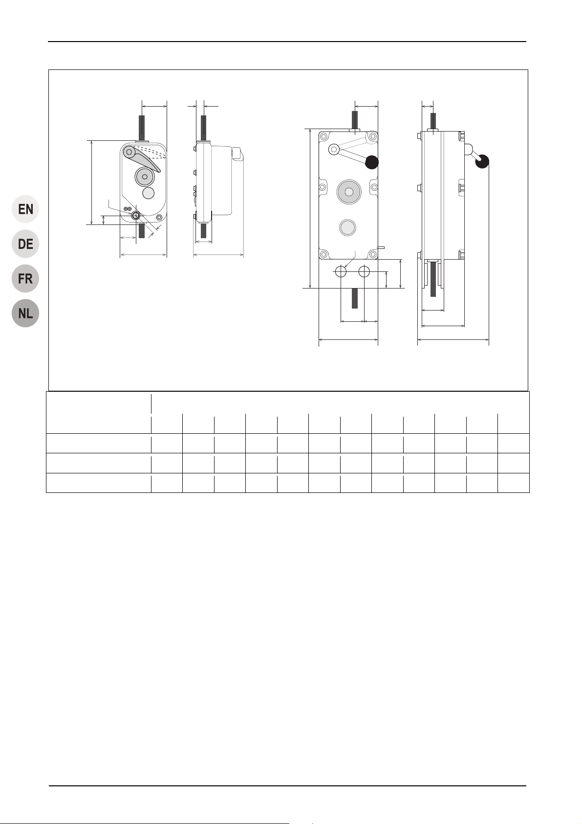
Fig./Abb./Fig./Afb. 3
Measure in mm / Maß in mm / Mesure en mm / Maat in mm
a a1 b c1 c2 c3 d1 d2 e f g Ø h
BSO 500/510/520 214 — 121 131 40 — 64 20 40 12,5 21,5 12,2
BSO 1000/1020/1030/1040 251 — 140 131 40 — 65 20 56 12,5 21,5 12,2
BSO 2050/2360 409 70 150 183 110 55 60 27,5 35 60 36 22,2
Table/Tabelle/Tableau/Tabel 2
EN-DE-FR-NL-IV G905.5 - 02/2011
Page 5
blocstop™ BSO
V
2
OUVRIR
OPEN
AUF
ZU
ZU
CLOSE
CLOSE
FERMER
FERMER
Fig./Abb./Fig./Afb. 4
blocstop
Fangvorrichtung
Fall arrest device
TM
Typ (e): BSO
Original Tractel -®Se
il/
rope Ø:
Fabr.Nr./Serial No
Bauj./Year of man
201
Bei Rückfragen/Ersatzteilbestellungen
bitte Typ und Fabr.Nr. angeben!
In case of queries / spare part o rders
please mention type and serial number!
Scheidtbachstraße 19-21
D-51469 Bergisch Gladbach
S248.1 12/09 102090
1
kg
kg
mm
00325/1
Fig./Abb./Fig./Afb. 7
Fig./Abb./Fig./Afb. 5
Fig./Abb./Fig./Afb. 8
00328/0
Fig./Abb./Fig./Afb. 6
Fig./Abb./Fig./Afb. 9
G905.5 - 02/2011 EN-DE-FR-NL-
Page 6
blocstop™ BSO
2
3
Fig./Abb./Fig./Afb. 10
CLOSE
CLOSE
FERMER
FERMER
OUVRIR
OPEN
AUF
ZU
ZU
1
00302/0
Fig./Abb./Fig./Afb. 12
Fig./Abb./Fig./Afb. 11
EN-DE-FR-NL-VI G905.5 - 02/2011
Page 7

Installation and operating manual
Contents
1 General ............................................................................... 2
1.1 Terms and abbreviations used in this manual .......... 2
1.2 Symbols used in this manual .................................... 3
2 Safety .................................................................................. 3
2.1 General safety instructions ....................................... 3
2.2 Instructions for the operator ...................................... 4
2.3 System manufacturer's responsibilities..................... 4
3 Overview............................................................................. 5
3.1 Delivery state ............................................................ 5
3.2 Scope of delivery ...................................................... 5
3.3 Equipment description .............................................. 5
4 Description ......................................................................... 6
4.1 Functional description ............................................... 6
4.2 Components / Modules ............................................. 7
4.3 Technical Specifications ........................................... 7
4.4 Operating fluids......................................................... 7
4.5 Circuit diagram.......................................................... 7
4.6 Safety equipment ...................................................... 7
4.7 Anchoring.................................................................. 7
5 Ropes.................................................................................. 8
6 Optional accessories......................................................... 8
13 Foreseeable misuse.........................................................14
14 Dismantling.......................................................................14
15 Transport and storage .....................................................14
15.1 Transport .................................................................14
15.2 Storage....................................................................15
16 Maintenance work ............................................................15
16.1 Authorized maintenance personnel.........................15
16.2 Mandatory inspections.............................................15
16.3 Care and maintenance ............................................15
16.4 Ordering spare parts................................................16
17 Disposal and environmental protection.........................16
18 Troubleshooting...............................................................17
19 EU Declaration of Conformity (Extract)..........................18
19.1 Independent secondary brake for
transport of persons.................................................18
19.2 Independent secondary brake for
transport of materials...............................................20
DANGER!
7 Options ............................................................................... 8
8 Model versions................................................................... 8
9 Necessary accessories ..................................................... 8
10 Installation and commissioning....................................... 8
10.1 Directives and standards .......................................... 8
10.2 Checks to be undertaken before starting
installation................................................................. 8
10.3 Assembly .................................................................. 9
10.4 Commissioning ....................................................... 10
11 Operating / Operation...................................................... 11
11.1 Checks to be carried out before starting work ........ 11
11.2 Operation with personnel lifting equipment............. 11
11.3 Operation with material lifting equipment................ 12
11.4 Manual EMERGENCY-STOP................................. 12
11.5 Securing the load.................................................... 12
12 Immediate measures to be taken after an emergency-
stop ................................................................................... 12
12.1 Emergency-stops for personnel lifting equipment... 12
12.2 Emergency-stops for material lifting equipment...... 13
12.3 Measures to be taken after a problem or an
emergency-stop ...................................................... 13
Risk of injury caused by falling objects, malfunctions,
incorrect usage and incorrect operation!
Failure to follow these instructions:
can result in severe injuries or death,
can result in damage to the equipment.
– Read through this operating manual carefully before you
install and commission this machine.
– Follow the instructions and procedures specified in this
manual in order to ensure safe operation of the equipment.
G905.5 - 02/2011 EN-1
Page 8

Installation and operating manual
1 General
Date of issue
02/2011
Copyright
The copyright of this instruction manual remains with Greifzug
Hebezeugbau GmbH.
This instruction manual is intended only for the operators of the
systems described here and their staff. This instruction manual
must be available to the operating personnel at all times. Additional copies can be obtained on request.
No part of this instruction manual may be reproduced, distributed
or otherwise communicated without the permission of Greifzug
Hebezeugbau GmbH.
Legal proceedings may be implemented in the case of any infringements.
Manufacturer's address
Sales and service office:
Greifzug Hebezeugbau GmbH
Scheidtbachstraße 19-21
51469 Bergisch Gladbach, Germany
Postfach 20 04 40
51434 Bergisch Gladbach, Germany
Tel: +49 (0) 22 02 / 10 04-0
Fax: +49 (0) 22 02 / 10 04-50 + 70
Greifzug Hebezeugbau GmbH reserves the right to make
changes to the product described in this instruction manual as
part of their ongoing product improvement programme.
Customers can obtain documentation about other TRACTEL
products by requesting the documentation from companies within
the TRACTEL Group or service organisations appointed by the
TRACTEL Group. Please visit our TRACTEL website at:
www.tractel.com for further details regarding the hoisting gear
and related accessories; stationary or mobile working platforms
for moving around on the inside and outside of buildings; rigging;
block stops for heavy loads; personal safety harnesses to prevent falls; traction and rope tension measuring equipment, etc.
The TRACTEL Group and its dealer network also provide additional customer and repair services upon request.
1.1 Terms and abbreviations used in
this manual
The terms used in this instruction manual have the following
meanings:
System / Machine
Pursuant to the Machine Directive 2006/42/EC lifting equipment,
hoisting gear, safety equipment and rigging for lifting are re-
garded as machines. The term "system" or "machine" also describes the device in which the unit described here will be fitted.
System manufacturer
The system manufacturer (system planner, system manufacturer,
installer) is the company marketing the system and all of the
required components. The system manufacturer is responsible
for the design, manufacturing, assembly and marketing.
Rigging
Rigging consists of equipment which does not belong to the
hoisting gear and which creates a connection between the carrying means and the load or the carrying means and the load lifting
equipment (e.g. rope loops, round slings, shackles, swivel hooks,
eye hooks, deflection rollers).
Anchoring point
Part of the on-site suspended construction to which the suspension rope, the safety rope, deflection rollers and the hoisting gear
are anchored separately from one another.
Actuation
The independent secondary brake is triggered (EMERGENCY
STOP situation) by manual actuation or uncontrolled actuation
resulting from vibrations.
Operating personnel
Personnel who have been trained by the operator to operate the
product and are authorised to operate it.
Operating personnel (PAM)
An appointed person who has undergone the appropriate advanced training for working at heights and who, due to his knowledge and practical experience, is in the position to perform the
required operating tasks when provided with the necessary
instructions.
Operator
The operator is responsible for the correct operation of the system / equipment and also for adhering to the maintenance intervals and the undertaking of the service work.
Running hours
The running hours are the effective operating times of a hoist's
motor.
BSO
BSO is used in the text as the abbreviation for the blocstop™
BSO model described here.
Electrician
An electrician is someone who possesses sufficient knowledge
or has obtained the required qualification through training in
order to recognise the risks and avoid the dangers that can occur
when working with electricity.
Emergency stop
The independent secondary brake is triggered (emergency stop
situation, e.g. overspeed) in the event of a suspension cable
rupture or a hoist malfunction.
Independent secondary brake
A device for stopping the load lifting equipment in the event of
the suspension rope snapping or a malfunction, e. g. drive malfunction.
EN-2 G905.5 - 02/2011
Page 9
f
g
Overall suspended load
The overall suspended load is the actual suspended static load,
which is made up of the payload, the load lifting equipment's own
weight, the additional fittings, the wire ropes and the control and
connection cables.
Hoisting gear / machine for lifting loads
Device or equipment consisting of a device with load carrying
means for lifting or transporting loads (e.g. wire rope hoist or wire
rope hoist with rope and swivel hook).
Customer / end customer
The customer or end customer is the system manufacturer's
customer and can also be the operator.
Load lifting equipment (LAM)
A component or piece of equipment which does not belong to the
hoisting gear, which enables the load to be grasped and which is
attached between the machine and the load or to the load itself,
or is intended to be an integral component of the load. Rigging
and its components are also regarded as load lifting equipment.
Material lifting equipment (MAM)
Load lifting equipment for material.
Nominal load
The nominal load is the load that the product bears. The maximum nominal load corresponds to the load bearing capacity.
Personnel lifting equipment (PAM)
Personnel lifting equipment. Combined material and personnel
lifting equipment also counts here.
Specialist
An appointed person who has undergone the appropriate training
and who, due to his knowledge and practical experience, is able
to safely perform the required work when provided with the necessary instructions.
Products in contact with the rope
Products in contact with the rope include hoists, deflection rollers,
independent secondary brakes and other products that the rope
runs through or is in contact with.
Load bearing capacity
The load bearing capacity specifies the maximum approved load
for the product.
Carrying means
The carrying means is equipment connected to the hoisting gear
for attaching load lifting equipment, rigging or loads (e.g. a hook
permanently attached to the suspension rope).
Maintenance personnel
A person appointed by and trained by Greifzug Hebezeugbau
GmbH with a valid certificate, who is capable of safely performing
the required maintenance, inspection and service work when
provided with the required instructions.
Installation and operating manual
1.2 Symbols used in this manual
DANGER!
Type and source of danger
Result: e.g. death or severe injuries.
– Measures that must be taken to eliminate the danger.
ATTENTION!
Type and source of danger
Result: e.g. equipment or environmental damage.
– Measures that must be taken to eliminate any possible
damage.
Note:
This symbol is not used to indicate safety information but to
indicate information that will give you a better understanding of
the working procedures.
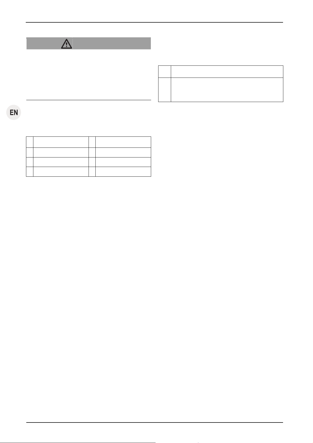
This symbol identifies devices for transport o
material.
This symbol identifies devices for transportin
people and materials.
2 Safety
2.1 General safety instructions
DANGER!
Danger of severe injuries caused by malfunctions, incorrect use and incorrect operation!
– You must abide by the following instructions in order to
ensure safe operation and correct functioning of the
equipment!
– Please observe the special safety instructions for all of
the work to be performed as described in the individual
chapters in this manual.
– Never use faulty or damaged independent secondary
brakes, rigging or ropes.
– The devices must only be used with an original rope with the
rope diameter specified in this manual.
G905.5 - 02/2011 EN-3
Page 10

Installation and operating manual
– Rope, hoist, independent secondary brake and rigging must
not be soiled by any heavily soiling building materials such
as concrete, epoxy resin or other adhesive materials. Protect the components against soiling! Utilize brush attachments to clean the wire rope in an extremely dirty environment.
– Do not lubricate the rope using a lubricant that contains
disulfide (e. g. Molycote
®
).
– Abide by the rope's withdrawal criteria, see '16.3 Care and
maintenance, Rope' on page 15.
– Cleaning the rope or the independent secondary brake with
high pressure cleaners is prohibited! Penetrating moisture
causes malfunctions.
– Dirt on the wire rope results in premature wear or the de-
struction of the rope, rigging and independent secondary
brake.
– Abide by the instructions concerning transport, storage and
cleaning listed on page 14.
– Always comply with the safety specification sheets provided
by the relevant manufacturers covering the lubricants to be
used.
– The anchoring devices must comply with the instructions
given in this manual or the applicable directives / standards.
– Never exceed the permitted load bearing capacity.
– Maintenance and repair work must only be undertaken by
authorised service personnel, see '16.1 Authorized mainte-
nance personnel' on page 15.
– Self-locking nuts must never be reused and they must al-
ways be exchanged for new ones.
– Only qualified personnel who have been trained on the
system are permitted to install and operate it in compliance
with the instructions given in this instruction manual.
– The independent secondary brake must be secured in place
so that the rope runs vertically into the independent secon-
dary brake from above. The independent secondary brake
must be aligned so that it does not touch the rope. The rope
must be tensioned using a tensioning weight or a relevant
winding device.
– Only qualified electricians or trainees supervised by a quali-
fied electrician are permitted to undertake work on the elec-
trical equipment in accordance with the electro technical
standards, rules and regulations.
– Never stand beneath suspended loads. Cordon off the
hazard zone whenever necessary. Support and secure
caught or jammed loads.
– Never grasp the wire rope while the machine is operating.
– When performing welding work the national safety and
accident prevention regulations must be observed (e.g.
BGR 159 in Germany).
2.2 Instructions for the operator
– If more than one person is entrusted with the tasks men-
tioned above then the operator must appoint a supervisor
who is authorised to issue instructions.
– The operator is also responsible for preparing clear operat-
ing, maintenance, repair and other working instructions and
ensuring that the unit is operated correctly by instructing and
training the personnel in the correct and approved utilisation
methods.
– Attached warning signs and information signs must be
readable at all times. Missing or illegible warning signs and
information signs must be replaced immediately.
– The operator is responsible for the correct operation of the
system as well as for adhering to the maintenance periods
and the undertaking of the service work.
– The operator is committed to maintaining the logbook sup-
plied with the system.
– EU Directive 89/391/EEC applies within the European Union
(in Germany Betriebssicherheitsverordnung (BetrSichV)).
You must always abide by your country's national accident
prevention regulations.
– You must provide suitable protective equipment such as
safety gloves, hearing protectors and a fall prevention system. Protection against extreme weather conditions (e.g.
sun protection, protection against cold) are also considered
to be part of the personal protective equipment.
– Always ensure that the workplace is sufficiently lit.
– This instruction manual and the instruction manuals for all of
the accessory parts must be handed out to all of the author-
ised personnel. The documents must be available at all ti-
mes.
– As Greifzug Hebezeugbau GmbH does not know the appli-
cations that the product described here will be used for in
the future, the system operator is therefore committed to in-
forming their personnel about any new safety instructions as
well as any supplementary maintenance work.
– The system operator is responsible for selecting the anchor-
ing method and suitable rigging options.
– The anchoring devices must comply with the instructions
given in this manual or the applicable directives / standards.
– Safe operation is not guaranteed if non-original spare parts
are utilised. This applies, in particular, to the use of ropes
other than the specified original ropes approved for the ap-
plication. Guarantee claims against the manufacturer will be
invalidated and this will also invalidate the CE approval for
any product holding this approval.
– Adhere to the permitted temperature range, see Table 1 on
page II.
2.3 System manufacturer's responsibili-
ties
– The system manufacturer is responsible for the design,
manufacture, assembly and marketing as well as obtaining
the CE seal of approval and issuing the EU Declaration of
Conformity.
– The products contained in the package supplied by Greifzug
Hebezeugbau GmbH must be carefully selected by the sys-
tem manufacturer, be used in the approved manner and in-
EN-4 G905.5 - 02/2011
Page 11

stalled in compliance with the instructions given in this installation and operating manual.
– The screw connections for anchoring the independent sec-
ondary brake and the clamp must be fitted in compliance
with the structural version.
– The information and notes contained in this installation and
operating manual must be integrated into the system manufacturer's operating manuals and documentation and supplemented by the addition of system specific details (e.g.
blockages and malfunction procedures). Merely handing this
manual over to the operator is insufficient.
– Instructions regarding the maintenance of the product and
its accessories must be integrated in the system's maintenance manual.
3 Overview
3.1 Delivery state
The equipment is delivered fully assembled.
3.2 Scope of delivery
y Independent secondary brake blocstop™ BSO
y Tractel
y Original Installation and operating manual
y Logbook
y Test certificate
y CE Declaration of Conformity
Optional scope of delivery:
y Lanyards
3.3 Equipment description
Authorized utilization
The blocstop™ BSO fitted with an automatic sudden acceleration
controller is an independent secondary brake, which can be used
with any hoisting gear / load lifting equipment. The device has
not been designed for private use. The precise intended use will
be defined by the operator or the equipment manufacturer.
An independent secondary brake is a safety component in accordance with the Machine Directive 2006/42/EC, Appendix V.
Safety components are regarded as machines.
The independent secondary brake must only be used with an
original rope with the rope diameter specified in this manual (see
also nameplate).
With the execption of the blocstop™ BSO 510, all of the equipment described here can be used as an independent secondary
®
rope in accordance with the order specifications
Installation and operating manual
brake for material and personnel lifting equipment, see (table 1
on page II).
The BSO 510 independent secondary brake may only be used to
hold material.
Maintenance and repair work must only be undertaken by authorised service personnel, see '16.1 Authorized maintenance personnel' on page 15.
Greifzug Hebezeugbau GmbH declares that the machine described in this instruction manual complies with technological
safety standards that were applicable to the equipment in the
European Union when it was launched on the market by the
manufacturer.
Commissioning the machine is prohibited until the machine in
which this is installed complies as a whole with the regulations of
the 2006/42/EC Directive, the corresponding national legislation
for implementing the regulations in accordance with national law
and the corresponding declaration of conformity has been issued.
y The operator or system manufacturer must perform a risk
evaluation in accordance with Appendix I of the guideline
2006/42/EC for machines for raising loads. EN 14492-1
must also be taken into account when inspecting the equip-
ment.
y A conformity evaluation process must be run by the operator
or the system manufacturer on machines used for lifting
personnel or personnel and goods, which come under Ap-
pendix IV No. 17 of Directive 2006/42/EC, in accordance
with Article 12, Paragraphs 3 or 4 of Directive 2006/42/EC.
EN 14492-1 and EN 1808 must also be taken into account
when inspecting the equipment.
The independent secondary brake must never be integrated in
systems that must comply with Directive 95/16/EC (in Germany:
Lift Directive 12 GPSGV).
Guarantee and liability exclusions
See '13 Foreseeable misuse' on page 14.
Any use other than that described here will be considered to be
unauthorised. Greifzug Hebezeugbau GmbH does not accept
any liability for damages resulting from unauthorised use. The
operator must assume sole responsibility in this case. Abiding by
all of the instructions given in this instruction manual, in particular
the installation and maintenance regulations, are also considered
part of authorised use.
Application areas
The product is suitable for use under the following operating
conditions:
y For permanent or temporary installations
y For short-term operation
y At heights of up to 1,000 m above sea level (max)
y Permitted temperature range see Table 1 on page II
G905.5 - 02/2011 EN-5
Page 12
Installation and operating manual
DANGER!
Danger of severe accidents!
– 24-hour operation is prohibited.
– Use in areas where there is a risk of explosion is prohib-
ited.
– Use in a corrosive environment is prohibited.
1)
– Use in close proximity to open fire or in an extremely hot
environment is prohibited.
1)
Corrosion protection in accordance with order specifications
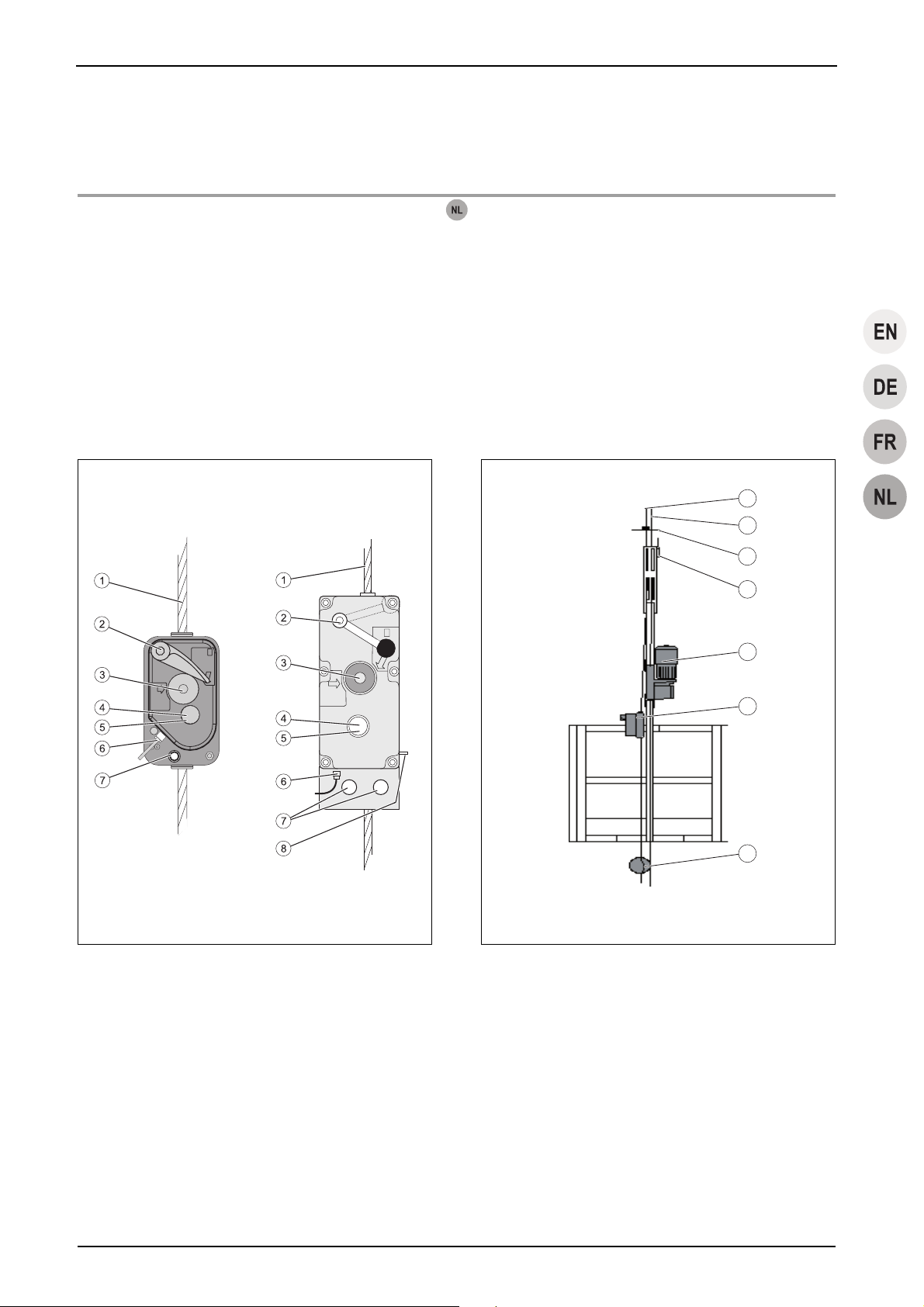
Installation example
See Fig. 2.
1 Safety rope 5 tirak™ hoist
2 Suspension rope 6 blocstop™ BSO
3 Limit switch actuator 7 Tension weight
4 "Lifting" limit switch
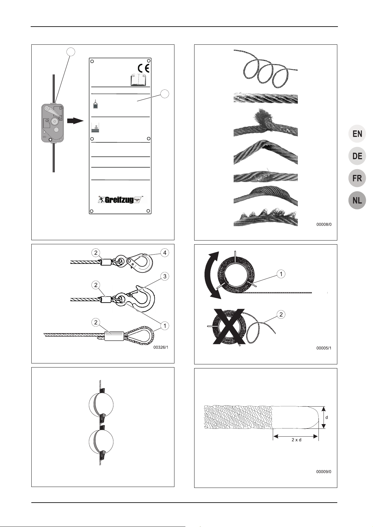
Nameplate and warning signs / application
restrictions
See Fig. 4.
Item Name
1 blocstop™ BSO nameplate
2 Rope diameter
The necessary information can be obtained from the nameplate.
Directives and standards
Applicable directives and standards: See '10.1 Directives and
standards' on page 8.
Product versions covered in the manual
The product versions described in this manual are listed in
Table 1 on page II.
Structural requirements
The maximum possible nominal load must be multiplied by the
operating coefficient in order to calculate the necessary load
bearing capacity.
The load bearing capacity of the structural equipment for anchoring the product, the rigging and the ropes must be at least the
nominal load bearing capacity multiplied by the operating coefficients:
Independent secondary brake: Operating coefficient = 5
The suspended assembly for the ropes and products must comply with the Directive 2006/42/EC and the applicable standards
(such as EN 1808).
The design must ensure that the impact factor remains below 3
(see EN 1808, 6.5.3.6) in the case of personnel lifting equipment
and securing to rigid assemblies. This is necessary in order to
ensure that the dynamic loading is adequate in the event of an
emergency stop.
The unit sizes of the different models can be found in Table 2 on
page IV.
Rope, products in contact with the rope and rigging must not be
soiled by heavily soiling building materials such as concrete,
epoxy resin or other adhesive materials. Protect the products
against soiling! Always use brush attachments to clean the wire
rope in an extremely dirty environment.
4 Description
4.1 Functional description
The independent secondary brake monitors the load lifting
equipment's speed. The independent secondary brake will stop
the downward movement of the load lifting equipment if the
speed is too high, using a friction actuated connection (clamps)
on the safety rope.
The independent secondary brake works automatically. The
speed of the safety rope is permanently monitored by a centrifugal force weight.
The centrifugal force balance weight will activate the clamping
jaws if a sudden acceleration occurs. The clamping jaws secure
the load to the safety rope. The clamping jaws are self clamping
jaws: The clamping jaws automatically shut tighter if the load
moves against the lifting direction. The greater the tractive force,
the tighter the clamping effect will be.
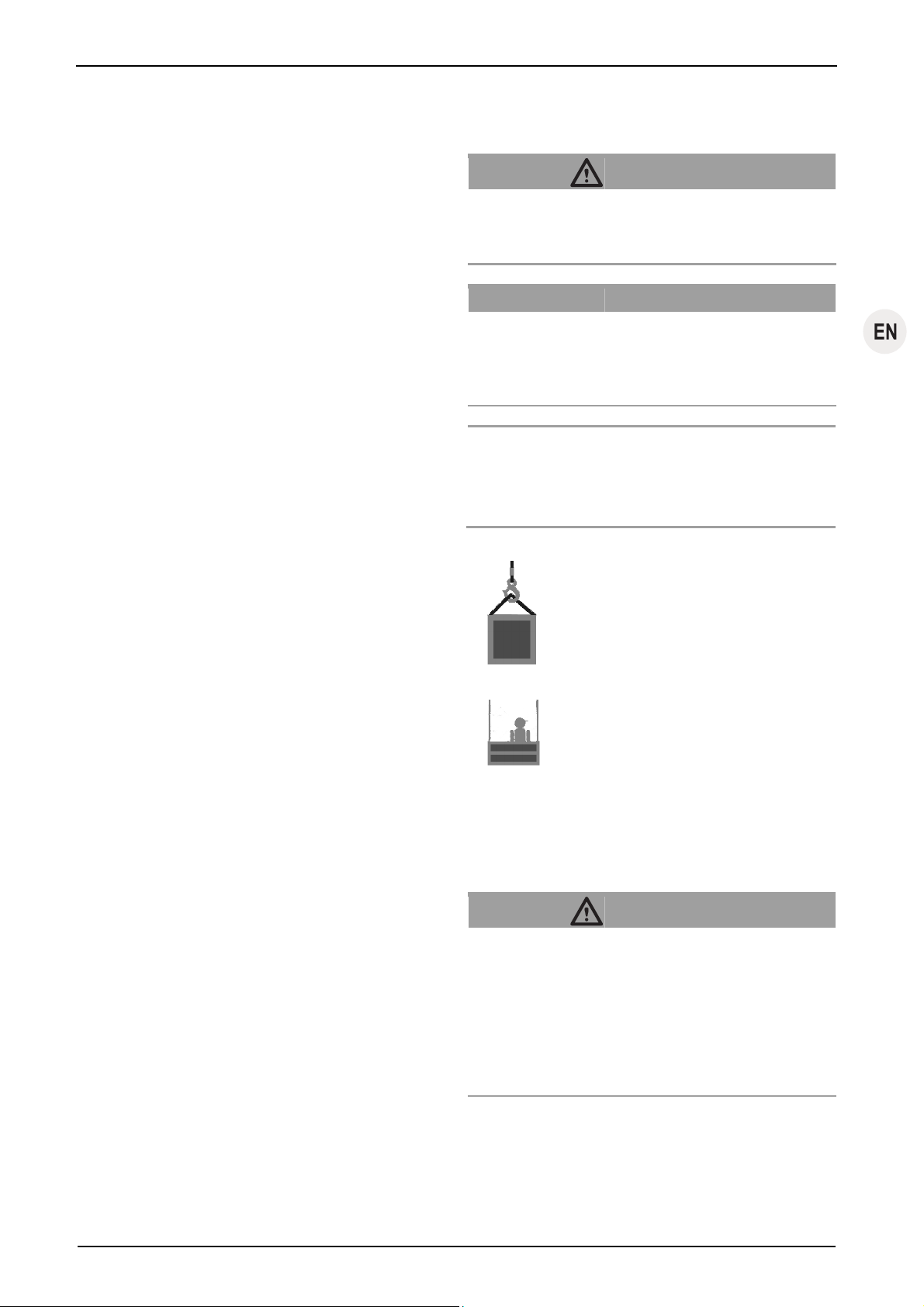
See Fig. 12.
When mounting the independent secondary brake the direction in
which the safety rope or the independent secondary brake accelerates in the event of the suspension rope snapping, for example,
so that the impulse to clamp the rope is triggered.
The braking direction (B) is the direction in which the independent secondary brake holds the end of the rope bearing the load.
The rope running direction (A) is the direction in which the rope
runs through the independent secondary brake regardless of
whether:
y the independent secondary brake is attached to a load
carrier or to a component and moves up and down a fixed
rope or
EN-6 G905.5 - 02/2011
Page 13
y the rope runs through a secondary brake mounted on-site,
for example.
The independent secondary brake must be mounted in such a
way that the direction (A) in which the rope runs through the
independent secondary brake at the time of the malfunction is
opposite to the braking direction (B).
This protects the hoisting gear / load lifting equipment against the
following damage:
y Suspension rope break
y Hoist malfunctions (broken gears)
Press the EMERGENCY-STOP button to manually trigger the
independent secondary brake in an emergency situation.
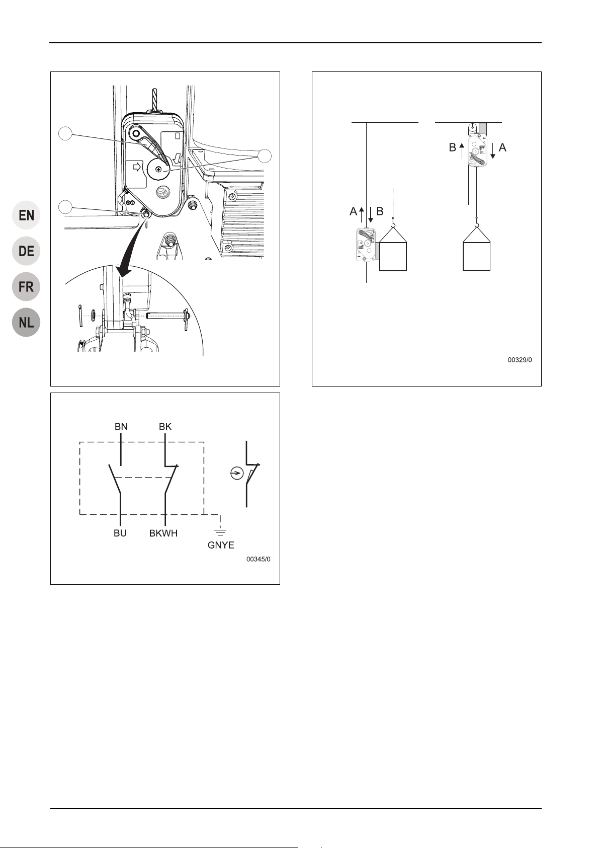
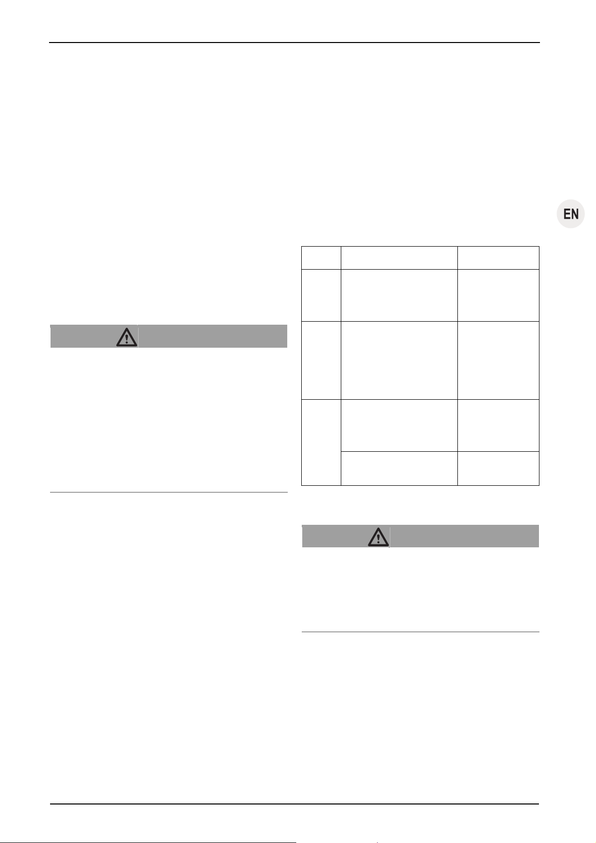
4.2 Components / Modules
See Fig. 1.
Item Name Function
1 Safety rope
2 Hand-lever Independent secondary brake release
3 EMERGENCY-
STOP button
Manually activates the independent
secondary brake
4 Inspection window Enables visual inspection of the function
of the centrifugal force mechanism during
operation
5 Centrifugal force
weight
Permanently monitors wire rope speed
during the run. The clamping jaw mechanism will be activated if the speed setting
is exceeded.
6 Clamping jaws Mechanical connection to the wire rope in
emergency-stop and activation situations.
The greater the tractive force, the tighter
the clamping effect will be.
7 Limit switches Optional
8 Securing holes Holds the bolts / screws used for securing
the independent secondary brake to the
anchoring devices
9 Control pin BSO 2050/2360 only: Visible when the
safety rope is running in correctly.
4.3 Technical Specifications
The technical specifications are listed in Table 1 on page II.
Installation and operating manual
4.4 Operating fluids
Lubricant
Application Lubricant
Rope Multipurpose oil/grease (without disul-
phide)
4.5 Circuit diagram
The hoist's circuit diagram is located in the terminal box of the
motor.
See '10.3 Assembly, Independent secondary brakes with limit
switch: Electrical connection' on page 10.
4.6 Safety equipment
Press the EMERGENCY-STOP button to manually trigger the
independent secondary brake in an emergency situation.
Optional for independent secondary brake with electrical deactivation:
The limit switch will ensure that the control voltage for the downward movement will be disconnected if an emergency-stop is
activated.
4.7 Anchoring
DANGER!
Danger of severe injuries caused by incorrect anchoring!
High-strength, galvanised bolts and screws can become brittle
and break. Risk of falling and of being injured by falling objects!
– High-strength galvanised bolts / screws (10.9 or 12.9)
may not be utilised for anchoring.
– Utilise bolts / screws with the specified strength.
Specifications detailing the strength of the bolts / screws are
listed in Table 1 on page II.
Observe the details in 'Structural requirements' on page 6.
The independent secondary brake must be secured in place so
that the rope runs vertically into the independent secondary
brake from above. The independent secondary brake must be
aligned so that it does not touch the rope. The rope must be
tensioned using a tensioning weight or a relevant winding device.
The required load bearing capability rating of the suspension and
securing modules depends on the independent secondary brake
model.
G905.5 - 02/2011 EN-7
Page 14

Installation and operating manual
5 Ropes
General
DANGER!
Incorrect rope or rope with incorrect diameter!
Using an incorrect rope leads to a danger of falling or injury
through falling objects and the risk of malfunctions!
– In order to operate safely only use original ropes author-
ized by Greifzug Hebezeugbau GmbH with the correct
rope diameter and the required design.
The required rope diameter is listed in Table 1 on page II.
The design is listed in Table 3 on page 16.
Alternative wire rope assemblies:
y End/thimble
y End/safety hook
6 Optional accessories
y Anchoring options e. g. fishplate sets
7 Options
10 Installation and commissioning
10.1 Directives and standards
The independent secondary brake fulfils the following directives
and standards:
y Machine Directive 2006/42/EC
y DIN EN ISO 12100
y Machines for lifting personnel or personnel and materials
(transport of persons):
EN 1808:1999 + A1:2010
The following are also applicable for independent secondary
brakes fitted with limit switches:
y The safety goals required by Directive 2006/95/EC have
been complied with in accordance with Appendix I No. 1.5 of
the Directive 2006/42/EC.
The operator or the system manufacturer is responsible for ensuring that the machine is used within the limits specified in these
instructions. The operator or the system manufacturer must also
observe the directives and standards and EN ISO 14121 and EN
ISO 13849 for the machine in which the unit will be fitted.
10.2 Checks to be undertaken before
starting installation
The independent secondary brake models described here are
can also be supplied with an optional limit switch fitted to them
(e.g. blocstop™ BSO 2030 E).
Please contact Greifzug Hebezeugbau GmbH directly.
8 Model versions
The standard stopping speed of the independent secondary
brakes described here is 30 m/min. Models with stopping speeds
of 20, 40, 60 and 70 m/min can also be supplied if requested.
9 Necessary accessories
The following accessories, which are not part of scope of delivery,
are necessary to use the product:
®
y Original Tractel
y Clamp (weights) for the rope, see Fig. 6
The operator or the manufacturer of the system is responsible for
selecting and using the accessories in accordance with the local
conditions. You must also abide by any other requirements of the
respectively applicable regulations and standards.
rope
Checking the suspended assembly
The suspended assembly for the ropes and products must comply with the Directive 2006/42/EC and the applicable standards
(such as EN 1808).
Observe the details in 'Structural requirements' on page 6.
Inspecting the installation site
– Check whether the device can be installed correctly without
it being obstructed by other components.
The installation space must not contain any sharp or edged
components.
– Check that the mounting does not cover any nameplates
(see Fig. 4).
– The independent secondary brake must be secured in place
so that the rope runs vertically into the independent secon-
dary brake from above. The independent secondary brake
must be aligned so that it does not touch the rope. The rope
must be tensioned using a tensioning weight or a relevant
winding device.
– The independent secondary brake must be mounted so that
the operator can trigger the EMERGENCY-STOP at any
time and can check the function via the inspection window.
Installation examples: When using personnel lifting equip-
ment e. g. on a working platform; when using material lifting
equipment e. g. at the operator's site.
EN-8 G905.5 - 02/2011
Page 15
See Fig. 12.
The independent secondary brake must be mounted in such a
way that the direction (A) in which the rope runs through the
independent secondary brake at the time of the malfunction is
opposite to the braking direction (B).
For independent secondary brakes equipped with a limit switch:
y Connection option available in the hoist's control box
Installation and operating manual
y Position of the securing module:
The gap between the securing module and the independent
secondary brake must be set up so that the rope runs verti-
cally into the inlet on the independent secondary brake.
Mounting the independent secondary brake
DANGER!
Checking the independent secondary brake
and the accessories
Independent secondary brake
– Inspect the housing for signs of damage.
Testing the EMERGENCY-STOP button:
– Trigger the independent secondary brake via the EMER-
GENCY-STOP button.
A clear audible click must be heard when it snaps shut.
Rope
– Check whether the diameter and design of the rope match
the product and the application, see Table 1 on page II,
Table 3 on page 16 and 'Nameplate and warning signs / application restrictions' on page 6.
– Check that the length of the rope is sufficient:
It must be possible to safely move the load from the start to
the end position.
The independent secondary brake requires a rope end of at
least 3 m.
– Check whether the thimble (1) and sealing cuffs (2) are
undamaged (see Fig. 5).
– Ropes with hooks:
Check that the hook and the safety catch (3) are intact, see
Fig. 5.
– Inspect the entire length of the rope for any signs of damage,
see Fig. 7.
– Inspect the rope tip in accordance with Fig. 9 (see also
'16.3 Care and maintenance, Rope' on page 15).
Anchoring devices
– Check whether the bolts/screws/rigging comply with the
specifications in '4.7 Anchoring' on page 7.
– Inspect the fishplates, load bolts and screw connections for
damage.
Danger of severe injuries caused by incorrect anchoring!
High-strength, galvanised bolts and screws can become brittle
and break. Risk of falling and of being injured by falling objects!
– High-strength galvanised bolts / screws (10.9 or 12.9)
may not be utilised for anchoring.
– Utilise bolts / screws with the specified strength.
Danger of severe injuries caused by incorrect anchoring!
Risk of falling and of being injured by falling objects!
– Both securing holes must be used to secure a blocstop™
BSO 2050 or 2360 to the securing module.
– The securing module must be fitted with two fishplates or
similar.
Depending on the application, observe the direction of the force
of the independent secondary brake (see also Fig. 12 and
'4.1 Functional description' on page 6).
– Attaching the independent secondary brake to the securing
module.
BSO 500 - BSO 1040: 1 bolt or 1 screw
BSO 2050 series, BSO 2360 series: 2 bolts or 2 screws
– Secure the bolts with a cotter pin or similar lock.
– Use screws with self-locking nuts to stop them from being
lost.
Installing the safety rope
DANGER!
Risk of injury through stabs and cuts!
Broken wires in the wire rope can result in protruding wires!
Protruding wires can cut or stab through safety gloves!
– Wear suitable leather protective gloves when working
with wire ropes.
– Never let the wire rope run through your hands!
10.3 Assembly
Requirements
y Assembly may only be performed by trained personnel.
y The workplace must have adequate lighting.
y The gap between the safety rope and the suspension rope
must be as small as possible.
Danger of severe injuries caused by incorrect anchoring!
There is a risk of malfunction if the independent secondary
brake cannot align with the rope.
– The independent secondary brake must be secured in
place so that the rope runs vertically into the independent
secondary brake from above.
– The independent secondary brake must be aligned so
that it does not touch the rope.
– The rope must be tensioned using a tensioning weight or
a relevant winding device.
G905.5 - 02/2011 EN-9
Page 16

Installation and operating manual
ATTENTION!
10.4 Commissioning
Incorrect assembly!
Damage to the rope may occur!
– The rope must never run over an edge!
– The loose rope end must hang free.
Note
Do not mix up the safety rope and the suspension rope: Observe
the correct rope diameter (see also Fig. 4).
– Roll-off the rope correctly so that no loops in the rope occur.
– Secure the rope to the suspended assembly. The rope must
hang free.
– Open the independent secondary brake by pressing down
on the manual lever.
– Feed the rope in from the top.
BSO 2050/2360: The control pin will spring out if the rope
has been fed in correctly.
– Manually pull the rope until it is taut.
– Clamp two tension weights (weighing approx. 11.5 kg) in
place about 20 cm above the ground (see Fig. 6).
– Place the loose end of the rope down correctly to prevent
any loops or knots from being created.
Independent secondary brakes with limit
switch: Electrical connection
The limit switch will ensure that the control voltage for the downward movement will be disconnected if an emergency-stop is
activated.
See Fig. 11.
Connection diagram for independent secondary brakes with limit
switch.
The switch must be connected as a break contact in order to
realise forced opening.
– Utilise the colours BK (black) and BKWH (black-white) for
the connection.
Limit switch cable with plug connection
– Connect the limit switch cable plug to the hoist's control box.
Hard-wired connection
Only a qualified electrician is permitted to undertake this work.
– Connect the limit switch cable inside the hoist's control box
as shown in the circuit diagram.
Determine operational readiness
– Check the rope anchoring.
– Inspect the connection between the independent secondary
brake and the load lifting equipment.
– Check whether the rope enters the independent secondary
brake vertically.
– Check whether the independent secondary brake can freely
align with the rope.
– Record the inspection results in the logbook.
Functional test
See Fig. 10 (example).
General function test:
– Inspect the housing for signs of damage.
– Press the EMERGENCY-STOP (1) button while moving
downward.
The independent secondary brake must close and hold the
rope.
Optional for independent secondary brakes equipped with a
limit switch:
The hoisting gear may not move downwards.
– Open the independent secondary brake: Turn the manual
lever (2) clockwise until it latches into place.
Check the function of the centrifugal force weight:
– Check the inspection window (4) during every run to see
whether the centrifugal force weight is turning.
Check the activation of the independent secondary brake:
The function of the speed limitation can be checked using two
different tests. The testing method depends on how the independent secondary brake is installed.
y Method 1: The independent secondary brake is removed,
raised approx. 30 cm and allowed to fall on the (vertical)
rope. The falling path may not be obstructed by any on-site
components which could collide with the independent secondary brake.
y Method 2: The safety rope is abruptly jerked through the
independent secondary brake by hand.
Method 1 (Checking the speed limitation):
DANGER!
Danger of being injured by falling objects! Danger of
crushing and cutting!
When performing the following test there is a risk of being
crushed between and cut by the falling independent secondary brake and the on-site components.
– Do not reach into the falling path of the independent
secondary brake.
EN-10 G905.5 - 02/2011
Page 17

Installation and operating manual
DANGER!
Danger of being injured by falling objects! Danger of
crushing and cutting!
If the independent secondary brake fails to activate and the
falling path is not cordoned off by on-site equipment then the
independent secondary brake can fall unchecked and endanger other people!
– Use suitable measures to cordon off the falling path!
ATTENTION!
Danger of damage to the independent secondary brake
or other components!
When performing the following test the independent secondary brake can collide with other on-site equipment and be
damaged.
– Ensure that the independent secondary brake cannot
collide with on-site equipment.
– If a collision cannot be avoided than use the other
testing method.
– Remove the independent secondary brake anchoring (e.g.
via the bolts (3) in the installation example shown).
– Raise the independent secondary brake approx. 30 cm up
the rope.
– Let the independent secondary brake fall:
The independent secondary brake must close and clamp
onto the rope after a maximum of 8 cm.
– Open the independent secondary brake: Turn the manual
lever (2) clockwise until it latches into place.
– Lower the independent secondary brake down the rope.
– Mount the independent secondary brake:
Secure the bolts with a new cotter pin.
Secure the screws with a new self-locking nut.
Method 2 (Checking the speed limitation):
See Fig. 12.
– Remove the tensioning weight from the safety rope or cre-
ate a rope loop at the rope outlet (the unloaded side of the
independent secondary brake).
– Abruptly jerk the rope in the direction 'A':
The independent secondary brake must close and hold the
rope.
– Open the independent secondary brake: Turn the manual
lever (2) clockwise until it latches into place.
– Re-tighten the safety rope by hand, if necessary.
– Re-attach the tensioning weight to the safety rope, if neces-
sary.
11 Operating / Operation
Personnel must have been trained by the operator in operating
the unit and be authorised to use it.
11.1 Checks to be carried out before
starting work
– Check the rope for clinging dirt and clean if necessary.
– Check that everything is ready for working, see
'10.4 Commissioning, Determine operational readiness' on
Page 10.
– Run the function test, see '10.4 Commissioning, Functional
test' on page 10.
– Record the inspection results in the logbook.
11.2 Operation with personnel lifting
equipment
DANGER!
Danger of being injured by an emergency-stop due to
the drop being too long!
The safety rope will be pushed upwards when moving
upwards with the independent secondary brake shut and it
will no longer be tensioned between the suspension point
and the independent secondary brake!
– You must always ensure that the manual lever is set to
OPEN and latched in place before moving.
See Fig. 10 (example).
– Open the independent secondary brake: Turn the manual
lever (2) clockwise until it latches into place.
– Start the hoisting gear.
– Check the inspection window (4) during every run to see
whether the centrifugal force weight is turning.
Note:
Where possible perform this check when beginning to move and
before the load lifting equipment has reached a great height.
If the centrifugal force weight does not turn:
– Immediately stop the load lifting equipment.
– Observe the operator’s emergency plan.
– Remove the independent secondary brake and send it to
Greifzug Hebezeugbau GmbH or an authorised hoisting
gear workshop for inspection.
Safety rope is not tensioned
If the safety rope is not under tension when the independent
secondary brake is closed:
G905.5 - 02/2011 EN-11
Page 18

Installation and operating manual
– Stop the hoisting gear.
– Check whether the safety rope is hanging free.
– Open the independent secondary brake: Turn the manual
lever (2) clockwise until it latches into place.
– Re-tighten the safety rope by hand, if necessary.
– Only continue with the original movement after the safety
rope has been re-tensioned.
11.3 Operation with material lifting
equipment
See Fig. 10 (example).
– Open the independent secondary brake: Turn the manual
lever (2) clockwise until it latches into place.
– Start the hoisting gear.
– Check the inspection window (4) during every run to see
whether the centrifugal force weight is turning.
If the centrifugal force weight does not turn:
– Immediately stop the load lifting equipment.
– Remove the independent secondary brake and send it to
Greifzug Hebezeugbau GmbH or an authorised hoisting
gear workshop for inspection.
See Fig. 10 (example).
Securing the load:
– Trigger the independent secondary brake via the EMER-
GENCY-STOP button.
Re-open the independent secondary brake:
– Move upwards slightly to reduce the strain on the rope.
– Open the independent secondary brake: Turn the manual
lever (2) clockwise until it latches into place.
– Re-tighten the safety rope by hand, if necessary.
– Only continue with the original movement after the safety
rope has been re-tensioned.
12 Immediate measures to be
taken after an emergency-stop
An emergency-stop means that the independent secondary
brake was triggered by a hoist malfunction or suspension rope
breakage, for example.
12.1 Emergency-stops for personnel lift-
ing equipment
Safety rope is not tensioned
If the safety rope is not under tension when the independent
secondary brake is closed:
– Stop the hoisting gear.
– Check whether the safety rope is hanging free.
– Open the independent secondary brake: Turn the manual
lever (2) clockwise until it latches into place.
– Re-tighten the safety rope by hand, if necessary.
– Only continue with the original movement after the safety
rope has been re-tensioned.
11.4 Manual EMERGENCY-STOP
Press the EMERGENCY-STOP button to manually trigger the
independent secondary brake in an emergency situation.
11.5 Securing the load
The independent secondary brake can be used to secure the
load during work breaks. This relieves the strain on the rope hoist
gearbox, for example.
Note:
– Please follow the operator's work instructions and safety
measures and the notes in the operating manuals for the
hoisting gear and load lifting equipment.
DANGER!
Danger of severe injuries caused by incorrect procedures!
– Keep calm.
– Check out the cause.
– Eliminate the problem.
If this was caused by a suspension rope snapping or a hoist
malfunction:
– Evacuate the team. See the personnel lifting equipment
documentation or, if available, the operators' emergency
rescue plan.
– Implement suitable measures to secure the personnel lifting
equipment in place so that the suspension rope or the hoisting gear can be replaced.
– Tension the safety rope on the ground.
If this was not caused by a suspension rope snapping or a hoist
malfunction:
– Try to move upwards.
If this is not possible:
– Evacuate the team and secure the personnel lifting equip-
ment in place (see above).
See Fig. 10.
If it is possible to move upwards then an independent secondary
brake malfunction has probably occurred.
EN-12 G905.5 - 02/2011
Page 19
– Move upwards slightly to reduce the strain on the rope.
– Open the independent secondary brake: Turn the manual
lever (2) clockwise until it latches into place.
– Re-tighten the safety rope by hand, if necessary.
– Move downwards.
– Press the EMERGENCY-STOP (1) button while moving
downward.
Independent secondary brakes without limit switch:
– Lower the load until the independent secondary brake sup-
ports the load using the safety rope.
Independent secondary brakes with limit switch:
– Perform an emergency descent (see the documentation for
the hoist or the personnel lifting equipment) until the inde-
pendent secondary brake holds the load using the safety
rope.
If the load is not held:
– Evacuate the team and secure the personnel lifting equip-
ment in place (see above).
If the load is held:
– Move upwards slightly to reduce the strain on the rope.
– Open the independent secondary brake: Turn the manual
lever (2) clockwise until it latches into place.
– Move the load lifting equipment carefully downwards and be
ready to press the EMERGENCY-STOP button on the inde-
pendent secondary brake at any time.
After every emergency-stop:
See '12.3 Measures to be taken after a problem or an emergency-stop' on page 13.
12.2 Emergency-stops for material lifting
equipment
DANGER!
Danger of being injured by falling loads!
– Never stand beneath the material lifting equipment.
– Check the cause of the problem.
– Eliminate the problem.
If this was caused by a suspension rope snapping or a hoist
malfunction:
– Implement suitable measures to secure the load lifting
equipment in place so that the suspension rope or the hoist-
ing gear can be replaced.
If this was not caused by a suspension rope snapping or a hoist
malfunction:
– Try to move upwards.
If this is not possible:
– Securing the load lifting equipment (see above).
Installation and operating manual
See Fig. 10.
If it is possible to move upwards then an independent secondary
brake malfunction has probably occurred.
– Move upwards slightly to reduce the strain on the rope.
– Open the independent secondary brake: Turn the manual
lever (2) clockwise until it latches into place.
– Re-tighten the safety rope by hand, if necessary.
– Move downwards.
– Press the EMERGENCY-STOP (1) button while moving
downward.
If the load is not held:
– Take suitable measures to secure the load lifting equipment.
If the load is held:
– Move upwards slightly to reduce the strain on the rope.
– Open the independent secondary brake: Turn the manual
lever (2) clockwise until it latches into place.
– Move the load lifting equipment carefully downwards and be
ready to press the EMERGENCY-STOP button on the inde-
pendent secondary brake at any time.
After every emergency-stop:
See '12.3 Measures to be taken after a problem or an emergency-stop' on page 13.
12.3 Measures to be taken after a prob-
lem or an emergency-stop
DANGER!
Danger of severe accidents!
In the event of an emergency-stop the entire construction is
subjected to sudden forces. Damage to the suspended assembly, the anchoring devices, the rope and the independent
secondary brake is possible.
– The independent secondary brake must be inspected by
Greifzug Hebezeugbau GmbH or an authorised hoisting
gear workshop.
– A qualified specialist must perform an on-site inspection.
– Remove the independent secondary brake and send it to
Greifzug Hebezeugbau GmbH or an authorised hoisting
gear workshop for inspection.
On-site inspection to be carried out by a specialist:
y Safety rope
y Safety rope anchoring point
y On-site anchoring point of the independent secondary brake
and anchoring point on the load lifting equipment
y All bolts and screw connections
An inspection is not needed after an activation.
G905.5 - 02/2011 EN-13
Page 20

Installation and operating manual
13 Foreseeable misuse
Guarantee and liability claims for personal injuries and equipment damage will be rejected if they can be traced back to one or
more of the following causes:
y Unauthorized use of the product, the accessories or the
carrying means belonging to the product
y BSO 510: Lifting personnel
y Operating with a soiled rope
y Use in potentially explosive or corrosive environments
y Not adhering to the stipulated maintenance periods
y Cleaning with a high-pressure cleaner
y Incorrect installation, commissioning, operation, mainte-
nance or repairs
y Working with an electrical connection that does not corre-
spond to the details stipulated in this manual
y Poor monitoring of the parts and the accessories, which has
resulted in wear occurring
y Carrying out incorrect and unauthorised repairs
y Use of non-original spare parts
y Alteration of safety device settings
y Ignoring measurements and checks that would detect early
signs of damage
y Product overloaded
y Manual lever jammed / wedged in place
y Accidents caused by foreign bodies or acts of God
y The manufacturer will not accept any liability for damages
resulting from modifications and conversions made to the
products or from the use of non-original parts that have not
been authorized by the manufacturer.
y Never use faulty or damaged products, accessories and,
rigging.
y The safety rope was anchored to the same anchoring point
as the suspension rope
y Load lifted when the safety rope was slack
y Use with personnel lifting equipment with a hoist that has a
rope speed exceeding 18 m/min
For transport of persons:
y The independent secondary brake was installed on the
suspension rope
14 Dismantling
DANGER!
Risk of injury through stabs and cuts!
Broken wires in the wire rope can result in protruding wires!
Protruding wires can cut or stab through safety gloves!
– Wear suitable leather protective gloves when working
with wire ropes.
– Never let the wire rope run through your hands!
– Disconnect the tension weight from the safety rope.
ATTENTION!
Increased wear or damage due to incorrectly opened
independent secondary brake!
– Always press the independent secondary brake lever
to the stop and hold until the rope has been pulled out.
– Open the independent secondary brake: Turn the manual
lever (2) clockwise until it latches into place.
Press the manual lever up to the stop and hold it there.
– Pull the safety rope upwards by hand.
– Dismantling the independent secondary brake: Unscrew the
screws and bolts.
– Whilst lowering the ropes (1) you must wind them up in the
correct position or wind them onto a reel to ensure that there
are no loops (2), which would make the ropes unusable.,
see Fig. 8.
15 Transport and storage
15.1 Transport
General transporting instructions
Ensure that no damage occurs during the transporting.
Always use suitable transport equipment and get a second per-
son to help you with heavy components.
Rope
– Protect the ropes against direct sunlight, chemicals, soiling
and mechanical damage.
– Transport the ropes on the reels whenever possible.
– Rolled-up ropes without reels should be lifted and trans-
ported using a lifting strap.
– Minimise the load resulting from the dead weight as much
as possible.
EN-14 G905.5 - 02/2011
Page 21
15.2 Storage
General storage conditions
y Dry location (maximum of 75% relative humidity)
y Dust-free
y Even ambient temperature
Wire rope storage conditions:
y Lightly greased
y Avoid contact with chemicals (e.g. battery acid).
y Store without any mechanical crushing, pressure or tensile
stress.
Installation and operating manual
Contact Greifzug Hebezeugbau GmbH or your supplier with
regards to this test.
Exceptional tests
The independent secondary brake must be inspected by
Greifzug Hebezeugbau GmbH or an authorised hoisting gear
workshop.
See '12.3 Measures to be taken after a problem or an emergency-stop' on page 13.
16.3 Care and maintenance
Interval Work Implementation
16 Maintenance work
16.1 Authorized maintenance personnel
DANGER!
Risk of falling! Risk of being injured by falling objects!
Danger of death due to incorrectly carried out maintenance or
service work!
Maintenance and service work which requires the product to
be opened may only be performed by the following authorized
parties:
– The Greifzug Hebezeugbau GmbH
– Lifting equipment service companies authorized by
Greifzug Hebezeugbau GmbH
– Service personnel trained and certified by Greifzug He-
bezeugbau GmbH
16.2 Mandatory inspections
A written certificate is required for the annual safety inspection
and any exceptional tests. The inspections must be recorded in
the logbook included with delivery.
Prior to every use
Always check to ensure that the device is in an orderly working
condition before use, see '10.4 Commissioning' on page 10.
Annual safety inspection
The safety inspection must be carried out annually.
The safety inspection may only be undertaken by authorised
maintenance personnel, see '16.1 Authorized maintenance personnel' on page 15. Depending on the usage conditions (e.g.
operation in an extremely dirty environment), an intermediate
inspection may be necessary.
We recommend that the system is tested in our factory by
Greifzug Hebezeugbau GmbH.
Weekly
– Lubricate the safety rope
Operating personnel
– Clean the independent
secondary brake housing
1 x annually /
every 250
operating
hours of
– Inspect for clamping jaw
wear
– Check for pressure / drive
roller wear
Authorised maintenance personnel
the hoist
Whenever
necessary
– Replace the clamping jaws
– Replace the pressure / drive
Authorised maintenance personnel
rollers
– Replace the safety rope
Trained person nominated by the operator
Rope
DANGER!
Risk of injury through stabs and cuts!
Broken wires in the wire rope can result in protruding wires!
Protruding wires can cut or stab through safety gloves!
– Wear suitable leather protective gloves when working
with wire ropes.
– Never let the wire rope run through your hands!
Cleaning
Brush the dirt off soiled ropes when dry if necessary. Re-lubricate
as necessary.
G905.5 - 02/2011 EN-15
Page 22
Installation and operating manual
Lubrication
DANGER!
Danger of falling caused by a slippery safety rope!
May result in severe injuries or death!
– Never lubricate the safety rope using a lubricant that
®
contains disulfide (e.g. Molycote
).
– Use multi-purpose grease or oil.
– Cleaning the rope or the independent secondary brake
with high pressure cleaners is prohibited! Penetrating
moisture will result in malfunctions and damage.
– Dirt on the wire rope results in premature wear or the
destruction of the rope, rigging and independent secondary brake.
Replacement
Replace the ropes immediately if the withdrawal criteria in accor-
dance with Table 3 have been reached (as per ISO 4309 and
DIN 15020, Sheet 2) or typical rope defects are present, see
Fig. 7.
Design of the rope
4 x 26
rope
Nominal diameter of the
Rotation-resistant
4 x 36 5 x 19 5 x 26 5 x 31
diameter
Minimum permitted rope
16.4 Ordering spare parts
Spare parts lists can be requested from your supplier or directly
from Greifzug Hebezeugbau GmbH.
The details needed to place the order are listed on the separate
component's nameplates, see 'Nameplate and warning signs /
application restrictions' on page 6.
The required information is e.g.:
Independent
Article no., model
secondary brake:
17 Disposal and environmental
protection
The equipment is made from recyclable materials. If the equipment is later scrapped, it must be disposed off correctly. The
national versions of the waste legislation directive 75/442/EEC
apply within the European Union (in Germany Kreislaufwirtschafts- und Abfallgesetz (KrWAbfG)).
The manufacturer is obliged to take back and dispose of specific
electrical and electronic components in accordance with Directive
2002/96/EC. The following symbol is used on the nameplate of
such components to identify them:
[mm] Number of visible broken wires in the outer strands
[mm]
over a length of 30 x rope's nominal diameter.
6
8 5,9
8 10 10 8 11 7,5
9 10 10 8
10 8
8,5
11 9,3
11,5 10 11 10,5
14 10 11 13,1
16 13 13 15,0
Table 3
Implementation: See '14 Dismantling' on page 14 and
'10.3 Assembly' on page 9.
Renewing rope tips
Send the rope to Greifzug Hebezeugbau GmbH or an lifting
equipment service company authorised by Greifzug Hebezeugbau GmbH and have the tip replaced.
EN-16 G905.5 - 02/2011
Page 23

18 Troubleshooting
Fault
Cause Elimination
The independent secondary brake cannot be opened
Installation and operating manual
The independent secondary brake holds the load on the safety rope.
Mechanical defect.
– Move the load upwards on the suspension rope.
– Replace the independent secondary brake and send in for repair.
Independent secondary brake activated by normal downwards travel
Emergency stop
Hoisting gear speed too fast.
Independent secondary brake triggering speed set incorrectly.
Speed difference between suspension rope and safety rope too great
– See '12 Immediate measures to be taken after an emergency-stop'
– Check the hoisting gear.
– Replace the independent secondary brake and send in for repair.
– No tensioning weight on safety rope. Attach tensioning weight.
when starting movement.
The centrifugal force weight does not turn.
Soiling or defect.
Ice buildup
– Replace the independent secondary brake and send in for cleaning
– Carefully use hot air to heat it up (70 °C max).
BSO 2050/2360: The control pin is not visible after the safety rope has been fed in.
The rope has not been fed in correctly.
– Pull the rope out and feed it back in correctly.
on page 12.
or repair.
Mechanical defect.
– Replace the independent secondary brake and send in for repair.
Independent secondary brakes with limit switch: The hoisting gear moves upwards but not downwards.
Limit switch connection with the hoist controller has failed.
Wire breakage
Limit switch defective.
– Plug in connector.
– Have an electrician replace the wire.
– Have it checked by an electrician and return the independent sec-
ondary brake for repair if necessary.
The rope cannot be fed in.
Rope tip faulty.
– Renewing rope tips, see '16.3 Care and maintenance, Rope' on
page 15.
Independent secondary brake is closed.
– Open (clamp) the independent secondary brake.
G905.5 - 02/2011 EN-17
Page 24

Installation and operating manual
19 EU Declaration of Conformity (Extract)
19.1 Independent secondary brake for transport of persons
The manufacturer hereby declares
Greifzug Hebezeugbau GmbH
Scheidtbachstraße 19–21 51469 Bergisch Gladbach
represented by
Dr. Ing. Uwe Schuht
Managing Director
DECLARATION OF CONFORMITY
that the machine described complies with technological safety standards that were applicable to the equipment in the EUROPEAN
UNION when it was launched on the market by the manufacturer.
APPLICABLE DIRECTIVES AND STANDARDS:
2006/42/EC;
EN 1808; EN ISO 12100-1; EN ISO 12100-2; EN ISO 14121-1
DESIGNATION
Independent secondary brake
APPLICATION
Transport of persons
MODEL
BSO 500, BSO 520, BSO 1000, BSO 1020, BSO 1030, BSO 1040
SERIAL NUMBER
Year of manufacture
from 01.2010
The above-mentioned machine matches the model specified on the prototype testing certificate, approved by the following certificate
numbers
08 040
Commissioning the machine is prohibited until the machine in which this is installed complies as a whole with the regulations of the
2006/42/EC Directive, the corresponding national legislation for implementing the regulations in accordance with national law and the
corresponding declaration of conformity has been issued.
The valid EN 1808 standard must be applied for the PAM in which the machine is installed.
Issuer of the prototype testing certificate:
Fachausschuss MHHW
Test and certification centre BG-PRÜFZERT
Graf-Recke-Straße 69
40239 Düsseldorf
notified as No. 0393 at the European Union Commission
Responsible for the documentation:
Dr. Ing. Uwe Schuht, Tel.: +49 (0) 2202 1004 63
Bergisch Gladbach, date
EN-18 G905.5 - 02/2011
Page 25

Installation and operating manual
The manufacturer hereby declares
Greifzug Hebezeugbau GmbH
Scheidtbachstraße 19–21 51469 Bergisch Gladbach
represented by
Dr. Ing. Uwe Schuht
Managing Director
DECLARATION OF CONFORMITY
that the machine described complies with technological safety standards that were applicable to the equipment in the EUROPEAN
UNION when it was launched on the market by the manufacturer.
APPLICABLE DIRECTIVES AND STANDARDS:
2006/42/EC;
EN 1808; EN ISO 12100-1; EN ISO 12100-2; EN ISO 14121-1
DESIGNATION
Independent secondary brake
APPLICATION
Transport of persons
MODEL
BSO 2050, BSO 2360
SERIAL NUMBER
Year of manufacture
from 01.2010
The above-mentioned machine matches the model specified on the prototype testing certificate, approved by the following certificate
numbers
09 261
Commissioning the machine is prohibited until the machine in which this is installed complies as a whole with the regulations of the
2006/42/EC Directive, the corresponding national legislation for implementing the regulations in accordance with national law and the
corresponding declaration of conformity has been issued.
The valid EN 1808 standard must be applied for the PAM in which the machine is installed.
Issuer of the prototype testing certificate:
Fachausschuss Bau (BAU) und Tiefbau (TB)
Test and certification centre BG-PRÜFZERT
Landsberger Str. 309
80687 München
notified as No. 0393 at the European Union Commission
Responsible for the documentation:
Dr. Ing. Uwe Schuht, Tel.: +49 (0) 2202 1004 63
Bergisch Gladbach, date
G905.5 - 02/2011 EN-19
Page 26

Installation and operating manual
19.2 Independent secondary brake for transport of materials
The manufacturer hereby declares
Greifzug Hebezeugbau GmbH
Scheidtbachstraße 19–21 51469 Bergisch Gladbach
represented by
Dr. Ing. Uwe Schuht
Managing Director
DECLARATION OF CONFORMITY
that the machine described complies with technological safety standards that were applicable to the equipment in the EUROPEAN
UNION when it was launched on the market by the manufacturer.
APPLICABLE DIRECTIVES AND STANDARDS:
2006/42/EC;
EN ISO 12100-1; EN ISO 12100-2; EN ISO 14121-1
DESIGNATION
Independent secondary brake
APPLICATION
Transport of material
MODEL
BSO 510
SERIAL NUMBER
Year of manufacture
from 01.2010
Commissioning the machine is prohibited until the machine in which this is installed complies as a whole with the regulations of the
2006/42/EC Directive, the corresponding national legislation for implementing the regulations in accordance with national law and the
corresponding declaration of conformity has been issued.
Responsible for the documentation:
Dr. Ing. Uwe Schuht, Tel.: +49 (0) 2202 1004 63
Bergisch Gladbach, date
EN-20 G905.5 - 02/2011
Page 27
Montage- und Betriebsanleitung
Inhaltsverzeichnis
1 Allgemeines........................................................................ 2
1.1 Verwendete Begriffe und Abkürzungen .................... 2
1.2 Verwendete Symbole................................................ 3
2 Sicherheit ........................................................................... 3
2.1 Allgemeine Sicherheitshinweise ............................... 3
2.2 Hinweise für den Betreiber........................................ 4
2.3 Verantwortung des Anlagenherstellers ..................... 4
3 Übersicht ............................................................................ 5
3.1 Lieferzustand ............................................................ 5
3.2 Lieferumfang ............................................................. 5
3.3 Gerätebeschreibung ................................................. 5
4 Beschreibung..................................................................... 6
4.1 Funktionsbeschreibung............................................. 6
4.2 Komponenten/Baugruppen ....................................... 7
4.3 Technische Daten ..................................................... 7
4.4 Betriebsmittel ............................................................ 7
4.5 Stromlaufplan............................................................ 7
4.6 Sicherheitseinrichtungen........................................... 7
4.7 Befestigung ............................................................... 7
14 Demontage........................................................................14
15 Transport und Lagerung..................................................14
15.1 Transport .................................................................14
15.2 Lagerung .................................................................15
16 Instandhaltung..................................................................15
16.1 Autorisiertes Wartungspersonal...............................15
16.2 Erforderliche Prüfungen...........................................15
16.3 Pflege und Wartung .................................................15
16.4 Ersatzteile bestellen.................................................16
17 Entsorgung und Umweltschutz.......................................16
18 Fehlersuche / Störungsbeseitigung ...............................17
19 EG-Konformitätserklärung (Auszug)..............................18
19.1 Fangvorrichtung für den Personentransport............18
19.2 Fangvorrichtung für den Materialtransport...............20
GEFAHR!
5 Seile .................................................................................... 8
6 Optionales Zubehör........................................................... 8
7 Optionen ............................................................................. 8
8 Modellvarianten ................................................................. 8
9 Notwendiges Zubehör....................................................... 8
10 Installation und Inbetriebnahme ...................................... 8
10.1 Richtlinien und Normen............................................. 8
10.2 Prüfungen vor Beginn der Montage ..........................8
10.3 Montage ....................................................................9
10.4 Inbetriebnahme .......................................................10
11 Bedienung/Betrieb........................................................... 11
11.1 Prüfungen vor Arbeitsbeginn .................................. 11
11.2 Betrieb mit einem Personenaufnahmemittel ...........11
11.3 Betrieb mit einem Materialaufnahmemittel.............. 12
11.4 Manueller NOT-STOP............................................. 12
11.5 Sichern der Last...................................................... 12
12 Sofortmaßnahmen im Fangfall....................................... 12
Verletzungsgefahr durch herabfallende Gegenstände,
Fehlfunktionen, falsche Nutzung und Fehlbedienung!
Beachten Sie diese Anleitung nicht:
können schwerste Verletzungen und der Tod die Folge sein,
können Schäden am Gerät entstehen.
– Lesen Sie diese Anleitung sorgfältig durch, bevor Sie
dieses Gerät montieren und in Betrieb nehmen.
– Beachten Sie die Hinweise und Verhaltensregeln, die für
einen sicheren Betrieb des Geräts notwendig sind.
12.1 Fangfall bei Personenaufnahmemitteln .................. 12
12.2 Fangfall bei Materialaufnahmemitteln ..................... 13
12.3 Maßnahmen nach einer Störung
oder einem Fangfall ................................................ 13
13 Vorhersehbarer Missbrauch........................................... 14
G905.5 - 02/2011 DE-1
Page 28

Montage- und Betriebsanleitung
1 Allgemeines
Ausgabedatum
02/2011
Urheberrecht
Das Urheberrecht an dieser Anleitung verbleibt bei der Greifzug
Hebezeugbau GmbH.
Diese Anleitung ist nur für den Betreiber der darin beschriebenen
Anlagen sowie dessen Personal bestimmt. Diese Anleitung muss
dem Bediener jederzeit zugänglich sein. Weitere Exemplare
können angefordert werden.
Ohne Zustimmung der Greifzug Hebezeugbau GmbH dürfen
keine Bestandteile dieser Anleitung vervielfältigt, verbreitet oder
anderweitig mitgeteilt werden.
Zuwiderhandlungen können strafrechtliche Folgen haben.
Anschrift des Herstellers
Verkaufs- und Servicestelle:
Greifzug Hebezeugbau GmbH
Scheidtbachstraße 19-21
51469 Bergisch Gladbach, Deutschland
Postfach 20 04 40
51434 Bergisch Gladbach, Deutschland
Telefon: +49 (0) 22 02 / 10 04-0
Telefax: +49 (0) 22 02 / 10 04-50 + 70
Die Greifzug Hebezeugbau GmbH behält sich das Recht vor, im
Zuge der Produktverbesserung jegliche Änderungen an dem in
dieser Anleitung beschriebenen Produkt vorzunehmen.
Kunden können über die Unternehmen der TRACTEL-Gruppe
und die von der TRACTEL-Gruppe autorisierten Instandhalter auf
Anfrage Dokumentationen über andere TRACTEL-Produkte
erhalten: Hebezeuge und deren Zubehör, fest installierte oder
mobile Arbeitsbühnen zur Innen- und Außenbefahrung von Gebäuden, Anschlagmittel, Abfangsicherungen für Lasten, Persönliche Schutzausrüstung gegen Absturz, Zugkraft- und Seilspannungsmessgeräte, etc. Besuchen Sie hierfür auch die
TRACTEL–Website www.tractel.com.
Die TRACTEL-Gruppe und ihr Händlernetzwerk bieten Ihnen bei
Bedarf zusätzlich Kunden- und Reparaturservice.
1.1 Verwendete Begriffe und Abkürzungen
In dieser Anleitung haben die folgenden Begriffe diese Bedeutung:
Anlage / Maschine
Im Sinne der Maschinenrichtlinie 2006/42/EG gelten Lastaufnahmemittel, Hebezeuge, Sicherheitsbauteile und Anschlagmittel
zum Heben als Maschine. Mit Anlage oder Maschine wird auch
die Einrichtung bezeichnet, in die die hier beschriebene Maschine eingebaut wird.
Anlagenhersteller
Der Anlagenhersteller (Anlagenplaner, Anlagenhersteller, Montagebetrieb) ist der Inverkehrbringer der Anlage und aller notwendigen Komponenten. Der Anlagenhersteller ist für den Entwurf, die Herstellung, den Einbau und das Inverkehrbringen
verantwortlich.
Anschlagmittel
Anschlagmittel sind nicht zum Hebezeug gehörende Einrichtungen, die eine Verbindung zwischen Tragmittel und Last oder
Tragmittel und Lastaufnahmemittel herstellen (z. B. Seilschlaufen,
Rundschlingen, Schäkel, Wirbelhaken, Ösenhaken, Umlenkrollen).
Anschlagpunkt, Aufhängepunkt
Teil der bauseitigen Aufhängekonstruktion, an dem Tragseil,
Sicherheitsseil, Umlenkrollen oder das Hebezeug unabhängig
voneinander angeschlagen werden.
Auslösefall
Auslösen der Fangvorrichtung (NOT-STOP-Situation) hervorgerufen durch manuelles Auslösen oder unkontrolliertes Auslösen
durch Vibrationen.
Bediener
Person, die vom Betreiber in die Bedienung des Produktes eingewiesen und mit dem Gebrauch betraut ist.
Bediener (PAM)
Eine benannte und für Arbeiten in der Höhe entsprechend ausgebildete Person, die durch ihre Kenntnisse und praktischen
Erfahrungen in der Lage ist, mit den benötigten Anweisungen
versehen, die erforderlichen Bedienschritte auszuführen.
Betreiber
Der Betreiber ist für den ordnungsgemäßen Betrieb der Anlage/des Geräts sowie für die Einhaltung der Wartungsintervalle
und die Durchführung der Instandsetzungsarbeiten verantwortlich.
Betriebsstunden
Betriebsstunden sind die Summe der effektiven Betriebszeiten
des Motors einer Winde.
BSO
Im Text wird BSO als Abkürzung für die hier beschriebenen
Modelle der Fangvorrichtung blocstop™ BSO verwendet.
Elektrofachkraft
Elektrofachkraft ist, wer über ausreichende Kenntnisse verfügt
oder durch eine Ausbildung die notwendigen Qualifikationen
erworben hat, Risiken zu erkennen und Gefährdungen zu vermeiden, die von der Elektrizität ausgehen können.
Fangfall
Auslösen der Fangvorrichtung (Not-Stop-Situation, z.B. bei
Übergeschwindigkeit) infolge von Tragseilbruch oder Fehlfunktion der Winde.
Fangvorrichtung
Vorrichtung zum Abfangen von Lastaufnahmemitteln bei Tragseilbruch oder Störungen, z. B. Versagen des Antriebs der Winde.
DE-2 G905.5 - 02/2011
Page 29

Gesamt-Hängelast
Die Gesamt-Hängelast ist die auf die Aufhängung einwirkende
statische Last, die sich aus der Nutzlast, dem Eigengewicht des
Lastaufnahmemittels, der Zusatzausrüstung, den Drahtseilen
und den Steuer- und Anschlusskabeln zusammensetzt.
Hebezeug / Maschine zum Heben von Lasten
Gerät oder Einrichtung bestehend aus einem Gerät mit Tragmitteln zum Heben oder Transportieren von Lasten (z. B. Seilwinde
oder Seilwinde mit Seil und Wirbelhaken).
Kunde/Endkunde
Der Kunde oder Endkunde ist der Kunde des Anlagenherstellers
und kann gleichzeitig auch der Betreiber sein.
Lastaufnahmemittel (LAM)
Ein nicht zum Hebezeug gehörendes Bauteil oder Ausrüstungsteil, das das Ergreifen der Last ermöglicht und das zwischen
Maschine und Last oder an der Last selbst angebracht wird oder
das dazu bestimmt ist, ein integraler Bestandteil der Last zu
werden. Als Lastaufnahmemittel gelten auch Anschlagmittel und
ihre Bestandteile.
Materialaufnahmemittel (MAM)
Lastaufnahmemittel für Material.
Nennlast
Die Nennlast ist die Last, die auf das Produkt einwirkt. Die maximale Nennlast entspricht der Tragfähigkeit.
Personenaufnahmemittel (PAM)
Lastaufnahmemittel für Personen. Hierzu zählen auch Kombinationen von Lastaufnahmemitteln für Material und Personen.
Sachkundige Person
Eine benannte und entsprechend ausgebildete Person, die durch
ihre Kenntnisse und praktischen Erfahrungen in der Lage ist, mit
den benötigten Anweisungen versehen, die erforderlichen Arbeiten sicher auszuführen.
Seilberührende Produkte
Seilberührende Produkte sind Winden, Umlenkrollen, Fangvorrichtungen und sonstige Produkte, durch die das Seil hindurchläuft oder die mit Seilen im Kontakt sind.
Tragfähigkeit
Die Tragfähigkeit gibt an, für welche Last das Produkt zugelassen ist.
Tragmittel
Ein Tragmittel ist eine mit dem Hebezeug verbundene Einrichtung zur Aufnahme von Lastaufnahmemitteln, Anschlagmitteln
oder Lasten (z. B. ein mit dem Tragseil fest verbundener Haken).
Wartungspersonal
Eine benannte und von der Greifzug Hebezeugbau GmbH geschulte Person mit gültigem Zertifikat, die in der Lage ist, mit den
benötigten Anweisungen versehen, die erforderlichen Wartungs-,
Prüf- und Instandsetzungsarbeiten sicher auszuführen.
Montage- und Betriebsanleitung
1.2 Verwendete Symbole
GEFAHR!
Art und Quelle der Gefahr.
Folge: z. B. Tod oder schwere Verletzungen.
– Maßnahmen, mit denen die Gefahr vermieden wird.
ACHTUNG!
Art und Quelle der Gefahr.
Folge: z. B. Sachschäden oder Umweltschäden.
– Maßnahmen, mit denen Schäden vermieden werden.
Hinweis:
Dieses Symbol kennzeichnet keine Sicherheitshinweise, sondern
gibt Informationen zum besseren Verständnis der Abläufe.
Mit diesem Symbol sind Geräte für den Materialtransport gekennzeichnet.
Mit diesem Symbol sind Geräte für den Personen- und Materialtransport gekennzeichnet.
2 Sicherheit
2.1 Allgemeine Sicherheitshinweise
GEFAHR!
Gefahr von schweren Unfällen durch Fehlfunktionen,
falsche Nutzung und Fehlbedienung!
– Beachten Sie folgende Angaben, damit der sichere
Betrieb und die ordnungsgemäße Funktion des Gerätes
gewährleistet sind!
– Beachten Sie auch die speziellen Sicherheitshinweise für
alle auszuführenden Arbeiten in den einzelnen Kapiteln
dieser Anleitung.
– Fehlerhafte oder beschädigte Fangvorrichtungen, Seile oder
Anschlagmittel dürfen nicht eingesetzt werden.
– Die Geräte dürfen nur mit einem Original-Seil mit dem in
dieser Anleitung angegebenen Seildurchmesser verwendet
werden.
– Seil, Winde, Fangvorrichtung und Anschlagmittel dürfen
nicht mit stark verschmutzenden Baumitteln, wie z. B. Beton,
G905.5 - 02/2011 DE-3
Page 30

Montage- und Betriebsanleitung
Epoxidharz oder sonstigen haftenden Arbeitsmitteln verunreinigt werden. Schützen Sie die Bauteile vor Verunreinigungen! In stark verschmutzter Umgebung Bürstenvorsätze
für die Seilreinigung verwenden.
– Das Seil darf nicht mit Disulfid-haltigen Schmierstoffen (z. B.
Molycote
®
) geschmiert werden.
– Beachten Sie die Ablegereife des Seils, siehe '16.3 Pflege
und Wartung, Seil' auf Seite 15.
– Das Reinigen des Seils oder von Fangvorrichtungen mit
einem Hochdruckreiniger ist verboten! Eindringende Feuchtigkeit führt zu Fehlfunktionen.
– Schmutz am Seil führt zum vorzeitigen Verschleiß oder zur
Zerstörung von Seil, Anschlagmittel und Fangvorrichtung.
– Beachten Sie die Hinweise für Transport, Lagerung und
Reinigung ab Seite 14.
– Beachten Sie die Sicherheitsdatenblätter für die verwende-
ten Schmierstoffe des jeweiligen Herstellers.
– Befestigungsmittel müssen den Angaben in dieser Anleitung
bzw. den gültigen Normen/Richtlinien entsprechen.
– Die zulässige Tragfähigkeit darf nicht überschritten werden.
– Instandsetzungs- und Wartungsarbeiten dürfen nur von
autorisiertem Wartungspersonal durchgeführt werden, siehe
'16.1 Autorisiertes Wartungspersonal' auf Seite 15.
– Selbstsichernde Muttern dürfen nicht wiederverwendet
werden und müssen ausgetauscht werden.
– Montage und Bedienung dürfen nur durch geschultes und
eingewiesenes Personal unter Berücksichtigung dieser An-
leitung erfolgen.
– Die Fangvorrichtung muss so befestigt sein, dass das Seil
von oben senkrecht in die Fangvorrichtung einläuft. Die
Fangvorrichtung muss sich frei am Seil ausrichten können.
Das Seil muss mit einem Spanngewicht oder einer entspre-
chenden Aufwickelvorrichtung gespannt sein.
– Arbeiten an elektrischen Ausrüstungen dürfen nur von einer
Elektrofachkraft oder von unterwiesenen Personen unter
Leitung und Aufsicht einer Elektrofachkraft gemäß den
elektrotechnischen Normen, Vorschriften und Regeln vor-
genommen werden.
– Nicht unter schwebenden Lasten aufhalten. Wenn nötig,
Gefahrenbereich absperren. Verhakte oder verklemmte Las-
ten abfangen und sichern.
– Während des Betriebs nicht an das Seil greifen.
– Bei Schweißarbeiten sind die nationalen Sicherheits- und
Arbeitsschutzbestimmungen zu beachten (z.B. in Deutsch-
land BGR 159).
2.2 Hinweise für den Betreiber
– Ist mehr als eine Person mit einer der hier beschriebenen
Tätigkeiten betraut, so hat der Betreiber einen Aufsichtfüh-
renden zu bestimmen, der weisungsbefugt ist.
– Der Betreiber ist dafür verantwortlich, klare Bedienungs-,
Instandhaltungs-, Wartungs- und sonstige Betriebsanwei-
sungen bereitzustellen und durch Schulung und Anweisung
des Personals den sachgerechten und bestimmungsgemäßen Betrieb und die sachgerechte Bedienung des Geräts sicherzustellen.
– Angebrachte Warnaufkleber und Hinweisschilder müssen
jeder Zeit lesbar sein. Fehlende oder nicht mehr lesbareWarnaufkleber und Hinweisschilder müssen umgehend ersetzt werden.
– Der Betreiber ist für den ordnungsgemäßen Betrieb der
Anlage sowie für die Einhaltung der Wartungsintervalle und
die Durchführung von Wartungsarbeiten verantwortlich.
– Der Betreiber ist verpflichtet, das mitgelieferte Logbuch zu
führen.
– Innerhalb der Europäischen Union gilt die EU-Richtlinie
89/391/EWG (in Deutschland die Betriebssicherheitsverordnung (BetrSichV)). Die nationalen Arbeitsschutzbestimmungen im Betreiberland müssen beachtet werden.
– Stellen Sie geeignete Schutzausrüstung zur Verfügung, wie
z. B. Schutzhandschuhe, Gehörschutz und Absturzsicherung. Zur persönlichen Schutzausrüstung gehört auch der
Schutz gegen extreme Witterungsbedingungen (z. B. Sonnenschutz, Kälteschutz).
– Sorgen Sie immer für eine ausreichende Beleuchtung des
Arbeitsplatzes.
– Dem beauftragten Personal müssen diese Anleitung sowie
die Anleitungen der Zubehörteile ausgehändigt werden. Die
Dokumente müssen jederzeit zugänglich sein.
– Da die Greifzug Hebezeugbau GmbH den späteren Anwen-
dungsfall des hier beschriebenen Produkts nicht kennt, ist
der Betreiber dazu verpflichtet, sein Personal über weitere
Sicherheitshinweise sowie über ergänzende Wartungsarbeiten zu informieren.
– Für die Wahl der Befestigungsmethode und geeignete
Anschlagmöglichkeiten ist der Betreiber der Anlage verantwortlich.
– Befestigungsmittel müssen den Angaben in dieser Anleitung
bzw. den gültigen Normen/Richtlinien entsprechen.
– Wenn keine Original-Ersatzteile verwendet werden, ist der
sichere Betrieb nicht gewährleistet. Dieses gilt insbesondere,
wenn nicht die vorgeschriebenen und für die Anwendung
zugelassenen Original-Seile verwendet werden. Der Garantieanspruch gegenüber dem Hersteller entfällt. Bei Produkten mit CE-Kennzeichnung verliert diese ihre Gültigkeit.
– Beachten Sie den zulässigen Temperaturbereich, siehe
Tabelle 1 auf Seite II.
2.3 Verantwortung des Anlagenherstellers
– Der Anlagenhersteller ist für den Entwurf, die Herstellung,
den Einbau und das Inverkehrbringen sowie für die CEKennzeichnung der Anlage und die Ausstellung der EGKonformitätserklärung verantwortlich.
– Die im Lieferumfang der Greifzug Hebezeugbau GmbH
enthaltenen Produkte müssen vom Anlagenhersteller sorgfältig ausgewählt, bestimmungsgemäß verwendet und ge-
DE-4 G905.5 - 02/2011
Page 31

mäß den Angaben dieser Montage- und Bedienungsanleitung montiert werden.
– Die Schraubverbindungen zur Befestigung der Fangvorrich-
tung und der Spannvorrichtung müssen gemäß der bautechnischen Ausführung ausgelegt werden.
– Die Informationen und Hinweise dieser Montage- und Be-
triebsanleitung müssen in die Betriebsanleitung und Dokumentation des Anlagenherstellers eingearbeitet und durch
anlagenspezifische Angaben (z.B. Vorgehensweise bei Störungen und Blockierungen) ergänzt werden. Eine einfache
Weitergabe dieser Anleitung an den Betreiber ist nicht ausreichend.
– Angaben zur Wartung des Produkts und des Zubehörs
müssen in das Wartungsheft der Anlage eingearbeitet werden.
3 Übersicht
3.1 Lieferzustand
Die Lieferung erfolgt komplett montiert.
3.2 Lieferumfang
y Fangvorrichtung blocstop™ BSO
y Tractel
y Original-Montage- und Betriebsanleitung
y Logbuch
y Prüfzertifikate
y CE-Konformitätserklärung
Lieferumfang optional:
®
-Seil gemäß Bestellspezifikation
Montage- und Betriebsanleitung
Bis auf den BSO 510 dürfen alle hier beschriebenen Geräte als
Fangvorrichtung für Personen- und Materialaufnahmemittel
eingesetzt werden, siehe (Tabelle 1 auf Seite II).
Die Fangvorrichtung BSO 510 darf nur zum Abfangen von Material verwendet werden.
Instandsetzungs- und Wartungsarbeiten dürfen nur von autorisiertem Wartungspersonal durchgeführt werden, siehe
'16.1 Autorisiertes Wartungspersonal' auf Seite 15.
Die Greifzug Hebezeugbau GmbH erklärt, dass die in dieser
Anleitung beschriebene Maschine den technischen Sicherheitsbestimmungen entspricht, die zum Zeitpunkt des Inverkehrbringens in der Europäischen Union durch den Hersteller für die
Ausrüstung gelten.
Die Inbetriebnahme der Maschine ist solange verboten, bis die
Maschine in welche diese eingebaut wird, als Ganzes den Bestimmungen der Richtlinie 2006/42/EG sowie dem entsprechenden nationalen Rechtserlass zur Umsetzung der Richtlinie in
nationales Recht entspricht und die entsprechende Konformitätserklärung ausgestellt ist.
y Für Maschinen zum Heben von Lasten muss durch den
Betreiber oder Anlagenhersteller eine Risikobeurteilung gemäß Anhang I der Richtlinie 2006/42/EG durchgeführt werden. EN 14492-1 muss bei der Anlagenplanung berücksichtigt werden.
y Für Maschinen zum Heben von Personen oder von Perso-
nen und Gütern, die unter Anhang IV Nr. 17 der Richtlinie
2006/42/EG fallen, muss durch den Betreiber oder Anlagenhersteller ein Konformitätsbewertungsverfahren gemäß
Artikel 12 Absätze 3 oder 4 der Richtlinie 2006/42/EG
durchgeführt werden. EN 14492-1 und EN 1808 müssen bei
der Anlagenplanung berücksichtigt werden.
Die Fangvorrichtung darf nicht in Anlagen eingebaut werden, die
der Richtlinie 95/16/EG (Aufzugsrichtlinie, in Deutschland: 12.
GPSGV) entsprechen müssen.
y Verbindungsmittel
3.3 Gerätebeschreibung
Gewährleistungs- und Haftungsausschlüsse
Siehe '13 Vorhersehbarer Missbrauch' auf Seite 14.
Jede von den hier genannten Angaben abweichende Verwen-
dung gilt als nicht bestimmungsgemäß. Für hieraus resultierende
Bestimmungsgemäßer Gebrauch
Der blocstop™ BSO mit Übergeschwindigkeitsautomatik ist eine
Fangvorrichtung, die bei jedem Hebezeug/Lastaufnahmemittel
eingesetzt werden kann. Das Gerät ist nicht für die private Verwendung vorgesehen. Der genaue Verwendungszweck wird
durch den Betreiber oder den Anlagenhersteller festgelegt.
Eine Fangvorrichtung ist gemäß Maschinenrichtlinie 2006/42/EG,
Anhang V ein Sicherheitsbauteil. Sicherheitsbauteile gelten als
Maschine.
Die Fangvorrichtung darf nur mit einem Original-Seil mit dem in
dieser Anleitung angegebenen Seildurchmesser verwendet
werden (siehe auch Typenschild).
Schäden haftet die Greifzug Hebezeugbau GmbH nicht. Das
Risiko trägt allein der Betreiber. Zur bestimmungsgemäßen
Verwendung gehört auch das Beachten aller Hinweise aus dieser Anleitung, insbesondere die Einhaltung der Montage- und
Instandhaltungsvorschriften.
Einsatzbereich
Das Produkt ist für folgende Betriebsbedingungen geeignet:
y Für Festeinbauten oder wechselnde Installationen
y Für kurzfristigen Betrieb
y In Höhenlagen bis maximal 1000 m über NN
y Zulässiger Temperaturbereich siehe Tabelle 1 auf Seite II
G905.5 - 02/2011 DE-5
Page 32

Montage- und Betriebsanleitung
GEFAHR!
Gefahr von schweren Unfällen!
– Der 24h-Betrieb ist verboten.
– Der Einsatz in explosionsgefährdeten Bereichen ist
verboten.
– Der Einsatz in korrosiver Umgebung ist verboten.
1)
– Der Einsatz in der Nähe von offenem Feuer oder in sehr
heißer Umgebung ist verboten.
1)
Korrosionsschutz gemäß Bestellspezifikation
Einbaubeispiel
Siehe Abb. 2.
1 Sicherheitsseil 5 tirak™-Winde
2 Tragseil 6 blocstop™ BSO
3 Auslöser für Endschalter 7 Spanngewicht
4 Endschalter „Heben“
Typenschilder und Hinweisschilder/Grenzen
der Anwendung
Siehe Abb. 4.
Pos. Bezeichnung
1 Typenschild blocstop™ BSO
2 Seildurchmesser
Auf dem Typenschild finden Sie notwendige Informationen.
Richtlinien und Normen
Zugrundeliegende Richtlinien und Normen: siehe
'10.1 Richtlinien und Normen' auf Seite 8.
Produktvarianten in der Anleitung
In dieser Anleitung werden die in Tabelle 1 auf Seite II aufgeführten Produktvarianten beschrieben.
Bauliche Voraussetzungen
Für die Berechnung der notwendigen Tragfähigkeit muss die
maximal mögliche Nennlast mit dem Betriebskoeffizienten multipliziert werden.
Die Tragfähigkeit der baulichen Einrichtungen für die Befestigung
des Produkts, der Anschlagmittel und der Seile muss mindestens
der Nennlast multipliziert mit dem Betriebskoeffizienten entsprechen:
Fangvorrichtung: Betriebskoeffizient = 5
Die bauseitige Aufhängekonstruktion für Seile und Produkte
muss entsprechend der Richtlinie 2006/42/EG und den geltenden Normen (wie z.B: EN 1808) ausgelegt sein.
Bei Personenaufnahmemitteln und Befestigung an starren Konstruktionen muss die Konstruktion so ausgelegt werden, dass der
Stoßfaktor unter 3 bleibt (siehe EN 1808, 6.5.3.6). Das ist notwendig, um der dynamischen Belastung im Fangfall zu genügen.
Die Einbaumaße der verschiedenen Modelle finden Sie in
Tabelle 2 auf Seite IV.
Seil, seilberührende Produkte und Anschlagmittel dürfen nicht
mit stark verschmutzenden Baumitteln, wie z. B. Beton, Epoxidharz oder sonstigen haftenden Materialien verunreinigt werden.
Schützen Sie die Produkte vor Verunreinigungen! In stark verschmutzter Umgebung Bürstenvorsätze für die Seilreinigung
verwenden.
4 Beschreibung
4.1 Funktionsbeschreibung
Die Fangvorrichtung überwacht die Geschwindigkeit des Lastaufnahmemittels. Bei Übergeschwindigkeit stoppt die Fangvorrichtung die Abwärtsbewegung des Lastaufnahmemittels durch
eine kraftschlüssige Verbindung (Klemmen) am Sicherheitsseil.
Die Fangvorrichtung arbeitet automatisch. Die Geschwindigkeit
des durchlaufenden Sicherheitsseils wird laufend durch ein
Fliehkraftgewicht überwacht.
Bei Übergeschwindigkeit löst das Fliehkraftgewicht die Klemmbacken aus. Die Klemmbacken fangen die Last am Sicherheitsseil ab. Die Klemmbacken arbeiten mit Selbstklemmung: Bewegt
sich die Last gegen die Heberichtung, ziehen sich die Klemmbacken zwangsläufig zu. Je höher dabei die Zugkraft, desto fester
die Klemmwirkung.
Siehe Abb. 12.
Beim Einbau der Fangvorrichtung ist zu berücksichtigen, in
welche Richtung das Sicherheitsseil bzw. die Fangvorrichtung
z. B. bei einem Tragseilbruch beschleunigt wird, so dass der
Impuls zum Halten des Seils ausgelöst wird.
Die Bremsrichtung (B) ist die Richtung, in der die Fangvorrichtung das Seilende mit der Last hält. Die Seildurchlaufrichtung (A)
ist die Richtung, in der das Seil durch die Fangvorrichtung läuft,
unabhängig davon ob:
y die Fangvorrichtung an einem Lastenträger oder an einem
Bauteil befestigt ist und sich an einen fixierten Seil auf und
ab bewegt oder
y das Seil sich durch eine z. B. bauseitig befestigte Fangvor-
richtung bewegt.
DE-6 G905.5 - 02/2011
Page 33

Die Fangvorrichtung muss so montiert werden, dass die Richtung (A), in der sich das Seil im Moment der Störung durch die
Fangvorrichtung bewegt, der Bremsrichtung (B) entgegengesetzt
ist.
Damit ist das Hebezeug/Lastaufnahmemittel gegen folgende
Schäden abgesichert:
y Bruch des Tragseils
y Versagen der Winde (Getriebebruch)
Mit der NOT-STOP-Taste kann die Fangvorrichtung im Notfall
von Hand ausgelöst werden.
4.2 Komponenten/Baugruppen
Siehe Abb. 1.
Pos. Bezeichnung Funktion
1 Sicherheitsseil
2 Handhebel Freischalten der Fangvorrichtung
3 NOT-STOP-Taste Manuelles Auslösen der Fangvorrich-
tung
4 Sichtfenster Sichtkontrolle der Funktion des Flieh-
kraftmechanismus während des
Betriebes
5 Fliehkraftgewicht Überwacht während der Fahrt perma-
nent die Seilgeschwindigkeit. Wird die
eingestellte Geschwindigkeit überschritten, löst es den KlemmbackenMechanismus aus.
6 Klemmbacken Mechanische Verbindung zum Seil im
Fang- und Auslösefall. Je höher die
Zugkraft, desto fester die Klemmwirkung.
7 Endschalter Optional
8 Befestigungsbohrung Aufnahme der Bolzen/Schrauben für
die Befestigung der Fangvorrichtung
am Befestigungsmittel
9 Kontrollstift Nur BSO 2050/2360: Ist bei ord-
nungsgemäß eingeführtem Sicherheitsseil sichtbar.
4.3 Technische Daten
Die technischen Daten finden Sie in Tabelle 1 auf Seite II.
Montage- und Betriebsanleitung
4.4 Betriebsmittel
Schmiermittel
Verwendung Schmiermittel
Seil Mehrzwecköl/-fett (ohne Disulfid)
4.5 Stromlaufplan
Der Stromlaufplan der Winde befindet sich im Klemmkasten des
Motors.
Siehe '10.3 Montage, Fangvorrichtung mit Endschalter: Elektrischer Anschluss auf Seite 10.
4.6 Sicherheitseinrichtungen
Mit der NOT-STOP-Taste kann die Fangvorrichtung im Notfall
von Hand ausgelöst werden.
Optional bei Fangvorrichtungen mit elektrischer Abschaltung:
Im Fangfall sorgt der Endschalter dafür, dass der Steuerstrom für
die Abwärtsfahrt unterbrochen wird.
4.7 Befestigung
GEFAHR!
Gefahr von schweren Unfällen durch unsachgemäße
Befestigung!
Hochfeste verzinkte Bolzen und Schrauben können spröde
werden und brechen. Absturzgefahr und Verletzungsgefahr
durch herabstürzende Gegenstände!
– Für die Befestigung dürfen keine hochfesten verzinkten
Bolzen/Schrauben (10.9 oder 12.9) verwendet werden.
– Verwenden Sie Bolzen/Schrauben mit der angegebenen
Festigkeit.
Angaben zur Festigkeit der Bolzen/Schrauben finden Sie in
Tabelle 1 auf Seite II.
Beachten Sie die Angaben in 'Bauliche Voraussetzungen' auf
Seite 6.
Die Fangvorrichtung muss so befestigt sein, dass das Seil von
oben senkrecht in die Fangvorrichtung einläuft. Die Fangvorrichtung muss sich frei am Seil ausrichten können. Das Seil muss
mit einem Spanngewicht oder einer entsprechenden Aufwickelvorrichtung gespannt sein.
Die notwendige Tragfähigkeit von Aufhängung und Befestigungsbauteil ist abhängig vom Modell der Fangvorrichtung.
G905.5 - 02/2011 DE-7
Page 34

Montage- und Betriebsanleitung
5 Seile
Allgemein
GEFAHR!
Falsches Seil oder Seil mit falschem Durchmesser!
Durch die Verwendung eines falschen Seils besteht Absturzgefahr, Verletzungsgefahr durch herabfallende Gegenstände
und die Gefahr von Fehlfunktionen!
– Für den sicheren Betrieb nur ein von der Greifzug Hebe-
zeugbau GmbH zugelassenes Original-Seil mit korrektem Seildurchmesser und der vorgeschriebenen Bauart
verwenden.
Den erforderlichen Seildurchmesser können Sie Tabelle 1 auf
Seite II entnehmen. Die Bauart können Sie Tabelle 3 auf
Seite 16 entnehmen.
Alternative Konfektionierungsarten der Seile:
y Spitze/Kausche
y Spitze/Sicherheitshaken
6 Optionales Zubehör
y Befestigungsmöglichkeiten, z. B. Laschensätze
10 Installation und Inbetriebnahme
10.1 Richtlinien und Normen
Die Fangvorrichtung entspricht den folgenden Richtlinien und
Normen:
y Maschinenrichtlinie 2006/42/EG
y DIN EN ISO 12100
y Maschinen zum Heben von Personen oder von Personen
und Gütern (Personentransport):
EN 1808:1999 + A1:2010
Für Fangvorrichtungen mit Endschalter gilt zusätzlich:
y Die Richtlinie 2006/95/EG wurde gemäß Anh. I Nr. 1.5 der
Richtlinie 2006/42/EG hinsichtlich ihrer Schutzziele eingehalten.
Der Betreiber oder der Anlagenhersteller ist dafür verantwortlich,
dass die Maschine in den in dieser Anleitung angegebenen
Grenzen verwendet wird. Die oben genannten Richtlinien und
Normen sowie EN ISO 14121 und EN ISO 13849 müssen auch
vom Betreiber oder Anlagenhersteller für die Maschine beachtet
werden, in die diese Maschine eingebaut wird.
10.2 Prüfungen vor Beginn der Montage
Prüfen der tragenden Konstruktion
7 Optionen
Die hier beschriebenen Modelle der Fangvorrichtung sind optional mit Endschalter erhältich (z. B. blocstop™ BSO 2030 E).
Bitte wenden Sie sich hierfür direkt an die Greifzug Hebezeugbau GmbH.
8 Modellvarianten
Die Standard-Abfanggeschwindigkeit der hier beschriebenen
Fangvorrichtungen beträgt 30 m/min. Auf Anfrage sind auch
Modelle mit Abfanggeschwindigkeiten von 20, 40, 60 und 70
m/min erhältlich.
9 Notwendiges Zubehör
Um das Produkt verwenden zu können, benötigen Sie folgendes
Zubehör, das nicht im Lieferumfang enthalten ist:
y Original-Tractel
y Spannvorrichtung (Gewichte) für das Seil, siehe Abb. 6
Der Betreiber oder der Anlagenhersteller ist dafür verantwortlich,
das Zubehör gemäß den örtlichen Gegebenheiten auszuwählen
und zu verwenden. Weitere Vorgaben in den jeweils gültigen
Regelwerken und Normen müssen beachtet werden.
®
-Seil
Die bauseitige Aufhängekonstruktion für Seile und Produkte
muss entsprechend der Richtlinie 2006/42/EG und den geltenden Normen (wie z.B: EN 1808) ausgelegt sein.
Beachten Sie die Angaben in 'Bauliche Voraussetzungen' auf
Seite 6.
Prüfen des Einbauortes
– Kontrollieren, ob eine fachgerechte Montage des Geräts
durch andere Bauteile behindert wird.
Im Einbauraum dürfen keine spitzen oder scharfkantigen
Bauteile vorhanden sein.
– Kontrollieren, dass durch die Befestigung keine Typenschil-
der (siehe Abb. 4) verdeckt werden.
– Die Fangvorrichtung muss so befestigt sein, dass das Seil
von oben senkrecht in die Fangvorrichtung einläuft. Die
Fangvorrichtung muss sich frei am Seil ausrichten können.
Das Seil muss mit einem Spanngewicht oder einer entsprechenden Aufwickelvorrichtung gespannt sein.
– Die Fangvorrichtung muss so angebracht werden, dass der
Bediener jederzeit die NOT-STOP-Taste auslösen und die
Funktion im Sichtfenster kontrollieren kann. Einbaubeispiele:
bei einem Personenaufnahmemittel z. B. auf der Arbeitsbühne, bei einem Materialaufnahmemittel z. B. am Bedienerstandort.
DE-8 G905.5 - 02/2011
Page 35

Siehe Abb. 12.
Die Fangvorrichtung muss so montiert werden, dass die Rich-
tung (A), in der sich das Seil im Moment der Störung durch die
Fangvorrichtung bewegt, der Bremsrichtung (B) entgegengesetzt
ist.
Bei Fangvorrichtungen mit Endschalter:
y Anschlussmöglichkeit im Steuerkasten der Winde
Montage- und Betriebsanleitung
y Position des Befestigungsbauteils:
Der Abstand zwischen Befestigungsbauteil und Fangvorrichtung muss so gewählt werden, dass das Seil senkrecht
in die Einlauföffnung der Fangvorrichtung einläuft.
Fangvorrichtung einbauen
GEFAHR!
Prüfen der Fangvorrichtung und des Zubehörs
Fangvorrichtung
– Gehäuse auf Schäden kontrollieren.
NOT-STOP-Taste testen:
– Fangvorrichtung mit der NOT-STOP-Taste auslösen.
Beim Schließen muss ein deutliches Klacken zu hören sein.
Seil
– Kontrollieren, ob der Durchmesser und die Bauart des Seils
zum Produkt und zum Anwendungsfall passen, siehe
Tabelle 1 auf Seite II, Tabelle 3 auf Seite 16 und
'Typenschilder und Hinweisschilder/Grenzen der Anwendung' auf Seite 6.
– Kontrollieren, ob die Länge des Seils ausreichend ist:
Die Last muss sicher bis zur Anfangs- und Endposition verfahrbar sein.
Für die Spannvorrichtung werden mindestens 3 m Seilende
benötigt.
– Prüfen, ob Kausche (1) und Pressmanschette (2) unbe-
schädigt sind (siehe Abb. 5).
– Seile mit Haken:
Kontrollieren, dass Haken und Sicherungsklappe (3) intakt
sind, siehe Abb. 5.
– Seil auf der gesamten Länge auf erkennbare Schäden
prüfen, siehe Abb. 7.
– Seilspitze entsprechend Abb. 9 prüfen (siehe auch
'16.3 Pflege und Wartung, Seil' auf Seite 15).
Befestigungsmittel
– Kontrollieren, ob die Bolzen/Schrauben/Anschlagmittel den
Vorgaben in '4.7 Befestigung' auf Seite 7 entsprechen.
– Laschen, Lastbolzen und Schraubverbindungen auf Schä-
den kontrollieren.
Gefahr von schweren Unfällen durch unsachgemäße
Befestigung!
Hochfeste verzinkte Bolzen und Schrauben können spröde
werden und brechen. Absturzgefahr und Verletzungsgefahr
durch herabstürzende Gegenstände!
– Für die Befestigung dürfen keine hochfesten verzinkten
Bolzen/Schrauben (10.9 oder 12.9) verwendet werden.
– Verwenden Sie Bolzen/Schrauben mit der angegebenen
Festigkeit.
Gefahr von schweren Unfällen durch unsachgemäße
Befestigung!
Absturzgefahr und Verletzungsgefahr durch herabstürzende
Gegenstände!
– blocstop™ BSO 2050 und 2360 müssen in beiden Boh-
rungen am Befestigungsbauteil befestigt werden.
– Das Befestigungsbauteil muss mit zwei Laschen o. ä.
ausgestattet sein.
Je nach Anwendungsfall beim Einbau die Kraftrichtung der
Fangvorrichtung beachten (siehe auch Abb. 12 und
'4.1 Funktionsbeschreibung' auf Seite 6).
– Fangvorrichtung am Befestigungsbauteil befestigen.
BSO 500 - BSO 1040: 1 Bolzen bzw. 1 Schraube
Serie BSO 2050, Serie BSO 2360: 2 Bolzen bzw. 2 Schrau-
ben
– Bolzen mit einem Klappsplint oder vergleichbarer Sicherung
sichern.
– Schrauben mit selbstsichernden Muttern gegen Verlust
sichern.
Sicherheitsseil installieren
GEFAHR!
10.3 Montage
Verletzungsgefahr durch Stiche und Schnitte!
Durch Drahtbrüche im Drahtseil können Drähte abstehen!
Voraussetzungen
y Die Montage darf nur durch geschultes Personal erfolgen.
y Der Arbeitsplatz muss ausreichend beleuchtet sein.
y Der Abstand zwischen Sicherheitsseil und Tragseil sollte
möglichst gering sein.
Abstehende Drähte können durch Schutzhandschuhe schneiden oder stechen!
– Geeignete schwere Lederschutzhandschuhe bei Arbeiten
am Drahtseil tragen.
– Drahtseil nicht durch die Hände gleiten lassen.
G905.5 - 02/2011 DE-9
Page 36

Montage- und Betriebsanleitung
GEFAHR!
Gefahr von schweren Unfällen durch unsachgemäße
Befestigung!
Wenn die Fangvorrichtung sich nicht am Seil ausrichten kann,
besteht die Gefahr einer Fehlfunktion.
– Die Fangvorrichtung muss so befestigt sein, dass das
Seil von oben senkrecht in die Fangvorrichtung einläuft.
– Die Fangvorrichtung muss sich frei am Seil ausrichten
können.
– Das Seil muss mit einem Spanngewicht oder einer ent-
sprechenden Aufwickelvorrichtung gespannt sein.
ACHTUNG!
Falsche Montage!
Schäden am Seil möglich!
– Seil nicht über Kanten führen.
– Das lose Seilende frei hängen lassen.
Hinweis
Sicherheitsseil und Tragseil nicht verwechseln: Korrekten Seildurchmesser beachten (siehe auch Abb. 4).
Endschalterkabel mit Steckverbindung
– Stecker des Endschalterkabels am Steuerkasten der Winde
anschließen.
Festverdrahtete Verbindung
Diese Arbeit darf nur durch eine Elektrofachkraft ausgeführt
werden.
– Endschalterkabel gemäß Stromlaufplan im Steuerkasten der
Winde anschließen.
10.4 Inbetriebnahme
Betriebsbereitschaft herstellen
– Befestigung des Seils kontrollieren.
– Verbindung zwischen Fangvorrichtung und Lastaufnahme-
mittel kontrollieren.
– Kontrollieren, ob das Seil senkrecht in die Fangvorrichtung
einläuft.
– Kontrollieren, ob die Fangvorrichtung sich frei am Seil aus-
richten kann.
– Ergebnis der Prüfungen schriftlich im Logbuch festhalten.
– Das Seil lagegerecht abrollen, damit keine Seilschlingen
entstehen.
– Das Seil an der tragenden Konstruktion befestigen. Das Seil
muss frei hängen.
– Fangvorrichtung durch Herunterdrücken des Handhebels
öffnen.
– Seil von oben durchstecken.
BSO 2050/2360: Wenn das Seil korrekt eingeführt wurde,
springt der Kontrollstift heraus.
– Seil von Hand straff ziehen.
– Zwei Spanngewichte mit jeweils ungefähr 11,5 kg ca. 20 cm
über dem Boden festklemmen (siehe Abb. 6).
– Loses Seilende fachgerecht ablegen, damit es keine
Schlaufen oder Knoten bilden kann.
Fangvorrichtung mit Endschalter: Elektrischer
Anschluss
Im Fangfall sorgt der Endschalter dafür, dass der Steuerstrom für
die Abwärtsfahrt unterbrochen wird.
Siehe Abb. 11.
Anschlussplan für Fangvorrichtungen mit Endschalter.
Der Schalter muss als Öffnerkontakt angeschlossen werden,
damit eine Zwangstrennung realisiert werden kann.
– Für den Anschluss die Farben BK (Black) und BKWH
(Black-White) verwenden.
Funktionstest
Siehe Abb. 10 (Beispiel).
Generelle Funktionsprüfung:
– Gehäuse auf Schäden kontrollieren.
– NOT-STOP-Taste (1) während der Abwärtsfahrt drücken.
Die Fangvorrichtung muss schließen und das Seil festhalten.
Optional bei Fangvorrichtungen mit Endschalter:
Das Hebezeug darf nicht abwärts fahren.
– Fangvorrichtung öffnen: Handhebel (2) im Uhrzeigersinn
schwenken, bis er einrastet.
Funktion des Fliehkraftgewichts prüfen:
– Während jeder Fahrt im Sichtfenster (4) prüfen, ob sich das
Fliehkraftgewicht dreht.
Auslösen der Fangvorrichtung prüfen:
Die Funktion der Geschwindigkeitsbegrenzung kann mit zwei
verschiedenen Tests überpüft werden. Die Prüfmethode ist
abhängig von der Einbausituation der Fangvorrichtung.
y Methode 1: Die Fangvorrichtung wird demontiert, ca. 30 cm
angehoben und am (senkrechten) Seil fallen gelassen. Im
Fallweg dürfen keine bauseitigen Bauteile vorhanden sein,
mit denen die Fangvorrichtung kollidieren könnte.
y Methode 2: Das Sicherheitsseil wird mit der Hand ruckartig
durch die Fangvorrichtung gezogen.
DE-10 G905.5 - 02/2011
Page 37
Methode 1 (Prüfen der Geschwindigkeitsbegrenzung):
GEFAHR!
Verletzungsgefahr durch herabfallende Gegenstände!
Quetsch- und Schergefahr!
Bei der folgenden Prüfung besteht Quetsch- und Schergefahr
zwischen der herunterfallenden Fangvorrichtung und bauseitigen Bauteilen.
– Fassen Sie nicht in den Fallweg der Fangvorrichtung.
Verletzungsgefahr durch herabfallende Gegenstände!
Quetsch- und Schergefahr!
Wenn die Fangvorrichtung nicht auslöst, und keine den Fallweg begrenzenden Bauteile vorhanden sind, kann die Fangvorrichtung unkontrolliert herunterfallen und andere Personen
gefährden!
– Begrenzen Sie den Fallweg ggf. durch geeignete Maß-
nahmen!
ACHTUNG!
Montage- und Betriebsanleitung
– Wenn nötig, Sicherheitsseil durch Ziehen von Hand wieder
spannen.
– Ggf. Spanngewicht am Sicherheitsseil wieder anbringen.
11 Bedienung/Betrieb
Der Bediener muss vom Betreiber in die Bedienung des Geräts
eingewiesen und mit dem Gebrauch betraut sein.
11.1 Prüfungen vor Arbeitsbeginn
– Seil auf anhaftende Verschmutzungen kontrollieren, ggf.
reinigen.
– Betriebsbereitschaft prüfen, siehe '10.4 Inbetriebnahme,
Betriebsbereitschaft herstellen' auf Seite 10.
– Funktionstest durchführen, siehe '10.4 Inbetriebnahme,
Funktionstest' auf Seite 10.
– Ergebnis der Prüfungen schriftlich im Logbuch festhalten.
Gefahr von Schäden an der Fangvorrichtung oder an
anderen Bauteilen!
Bei der folgenden Prüfung kann die Fangvorrichtung mit
bauseitigen Bauteilen kollidieren und beschädigt werden.
– Darauf achten, dass die Fangvorrichtung nicht mit bau-
seitigen Bauteilen kollidieren kann.
– Kann eine Kollision nicht ausgeschlossen werden, prüfen
Sie mit der anderen Prüfmethode.
– Befestigung der Fangvorrichtung entfernen (z. B. Bolzen (3)
im gezeigten Einbaubeispiel).
– Fangvorrichtung ca. 30 cm am Seil anheben.
– Fangvorrichtung fallen lassen:
Die Fangvorrichtung muss nach max. 8 cm schließen und
am Seil festhängen.
– Fangvorrichtung öffnen: Handhebel (2) im Uhrzeigersinn
schwenken, bis er einrastet.
– Fangvorrichtung am Seil herunterlassen.
– Fangvorrichtung montieren:
Bolzen mit einem neuen Splint sichern.
Schrauben mit einer neuen selbstsichernden Mutter sichern.
Methode 2 (Prüfen der Geschwindigkeitsbegrenzung):
Siehe Abb. 12.
– Spanngewicht am Sicherheitsseil entfernen oder am Seil-
auslauf (lastlose Seite der Fangvorichtung) eine Seilschlau-
fe erzeugen.
– Das Seil ruckartig in Richtung 'A' ziehen:
Die Fangvorrichtung muss schließen und das Seil festhal-
ten.
– Fangvorrichtung öffnen: Handhebel (2) im Uhrzeigersinn
schwenken, bis er einrastet.
11.2 Betrieb mit einem Personenaufnahmemittel
GEFAHR!
Verletzungsgefahr durch zu große Fallstrecke im Fangfall!
Bei Aufwärtsfahrt mit geschlossener Fangvorrichtung wird das
Sicherheitsseil hochgedrückt und ist zwischen Aufhängung
und Fangvorrichtung nicht mehr gespannt!
– Vor jeder Fahrt sicherstellen, dass der Handhebel auf
AUF steht und eingerastet ist.
Siehe Abb. 10 (Beispiel).
– Fangvorrichtung öffnen: Handhebel (2) im Uhrzeigersinn
schwenken, bis er einrastet.
– Hebezeug starten.
– Während jeder Fahrt im Sichtfenster (4) prüfen, ob sich das
Fliehkraftgewicht dreht.
Hinweis:
Diese Prüfung möglichst zu Beginn der Fahrt durchführen, bevor
das Lastaufnahmemittel eine große Höhe erreicht hat.
Wenn sich das Fliehkraftgewicht nicht dreht:
– Lastaufnahmemittel sofort stillsetzen.
– Notfall-Rettungsplan des Betreibers beachten.
– Fangvorrichtung ausbauen und zur Überprüfung an die
Greifzug Hebezeugbau GmbH oder eine autorisierte Hebe-
zeugwerkstatt schicken.
G905.5 - 02/2011 DE-11
Page 38
Montage- und Betriebsanleitung
Sicherheitsseil ist nicht gespannt
Wenn sich bei geschlossener Fangvorrichtung das Sicherheitsseil entspannt hat:
– Das Hebezeug anhalten.
– Kontrollieren, ob das Seil frei hängt.
– Fangvorrichtung öffnen: Handhebel (2) im Uhrzeigersinn
schwenken, bis er einrastet.
– Wenn nötig, Sicherheitsseil durch Ziehen von Hand wieder
spannen.
– Die Fahrt erst fortsetzen, wenn das Sicherheitsseil wieder
gespannt ist.
11.3 Betrieb mit einem Materialaufnahmemittel
Siehe Abb. 10 (Beispiel).
– Fangvorrichtung öffnen: Handhebel (2) im Uhrzeigersinn
schwenken, bis er einrastet.
– Hebezeug starten.
– Während jeder Fahrt im Sichtfenster (4) prüfen, ob sich das
Fliehkraftgewicht dreht.
Wenn sich das Fliehkraftgewicht nicht dreht:
– Lastaufnahmemittel sofort stillsetzen.
– Fangvorrichtung ausbauen und zur Überprüfung an die
Greifzug Hebezeugbau GmbH oder eine autorisierte Hebe-
zeugwerkstatt schicken.
Sicherheitsseil ist nicht gespannt
Wenn sich bei geschlossener Fangvorrichtung das Sicherheitsseil entspannt hat:
– Das Hebezeug anhalten.
– Kontrollieren, ob das Seil frei hängt.
– Fangvorrichtung öffnen: Handhebel (2) im Uhrzeigersinn
schwenken, bis er einrastet.
– Wenn nötig, Sicherheitsseil durch Ziehen von Hand wieder
spannen.
– Die Fahrt erst fortsetzen, wenn das Sicherheitsseil wieder
gespannt ist.
11.4 Manueller NOT-STOP
Mit der NOT-STOP-Taste kann die Fangvorrichtung im Notfall
von Hand ausgelöst werden.
11.5 Sichern der Last
Bei Arbeitsunterbrechungen kann die Fangvorrichtung zum
sichern der Last verwendet werden. Dadurch wird z. B. das
Getriebe der Seilwinde entlastet.
Hinweis:
– Beachten Sie die Arbeitsanweisungen und Sicherheitsmaß-
nahmen des Betreibers und die Hinweise aus den Betriebsanleitungen des Hebezeugs bzw. des Lastaufnahmemittels.
Siehe Abb. 10 (Beispiel).
Last sichern:
– Fangvorrichtung mit der NOT-STOP-Taste auslösen.
Fangvorrichtung wieder öffnen:
– Fahren Sie kurz aufwärts, um das Seil zu entlasten.
– Fangvorrichtung öffnen: Handhebel (2) im Uhrzeigersinn
schwenken, bis er einrastet.
– Wenn nötig, Sicherheitsseil durch Ziehen von Hand wieder
spannen.
– Die Fahrt erst fortsetzen, wenn das Sicherheitsseil wieder
gespannt ist.
12 Sofortmaßnahmen im Fangfall
Fangfall bedeutet, die Fangvorrichtung hat z. B. bei einem Getriebebruch der Winde oder bei einem Bruch des Tragseils ausgelöst.
12.1 Fangfall bei Personenaufnahmemitteln
GEFAHR!
Gefahr von schweren Unfällen durch falsches Verhalten!
– Ruhe bewahren.
– Ursache prüfen.
– Fehler beseitigen.
Wenn Bruch eines Tragseils oder ein Versagen des Hebezeugs
die Ursache ist:
– Evakuierung der Besatzung einleiten. Siehe Dokumentation
des Personenaufnahmemittels oder, wenn vorhanden, Notfall-Rettungsplan des Betreibers.
– Das Personenaufnahmemittel durch geeignete Maßnahmen
sichern, damit das Tragseil oder das Hebezeug ausgetauscht werden können.
– Das Sicherheitsseil am Boden verspannen.
Wenn Bruch eines Tragseils oder ein Versagen des Hebezeugs
ausgeschlossen werden kann:
– Versuchen Sie, aufwärts zu fahren.
Wenn das nicht möglich ist:
– Besatzung evakuieren und Personenaufnahmemittel sichern
(siehe oben).
DE-12 G905.5 - 02/2011
Page 39

Siehe Abb. 10.
Wenn eine Aufwärtsfahrt möglich ist, liegt wahrscheinlich eine
Störung der Fangvorrichtung vor.
– Fahren Sie kurz aufwärts, um das Seil zu entlasten.
– Fangvorrichtung öffnen: Handhebel (2) im Uhrzeigersinn
schwenken, bis er einrastet.
– Wenn nötig, Sicherheitsseil durch Ziehen von Hand wieder
spannen.
– Abwärts fahren.
– NOT-STOP-Taste (1) während der Abwärtsfahrt drücken.
Fangvorrichtung ohne Endschalter:
– Abwärts fahren, bis die Last mit der Fangvorrichtung am
Sicherheitsseil gehalten wird.
Fangvorrichtung mit Endschalter:
– Not-Ablass durchführen (siehe Dokumentation der Winde
oder des Personenaufnahmemittels), bis die Last mit der
Fangvorrichtung am Sicherheitsseil gehalten wird.
Wenn die Last nicht gehalten wird:
– Besatzung evakuieren und Personenaufnahmemittel sichern
(siehe oben).
Wenn die Last gehalten wird:
– Fahren Sie kurz aufwärts, um das Seil zu entlasten.
– Fangvorrichtung öffnen: Handhebel (2) im Uhrzeigersinn
schwenken, bis er einrastet.
– Das Lastaufnahmemittel vorsichtig abwärts fahren, dabei
jederzeit bereit sein, die NOT-STOP-Taste an der Fangvor-
richtung zu drücken.
Nach jedem Fangfall:
Siehe '12.3 Maßnahmen nach einer Störung oder einem Fangfall'
auf Seite 13.
Montage- und Betriebsanleitung
Wenn das nicht möglich ist:
– Lastaufnahmemittel sichern (siehe oben).
Siehe Abb. 10.
Wenn eine Aufwärtsfahrt möglich ist, liegt wahrscheinlich eine
Störung der Fangvorrichtung vor.
– Fahren Sie kurz aufwärts, um das Seil zu entlasten.
– Fangvorrichtung öffnen: Handhebel (2) im Uhrzeigersinn
schwenken, bis er einrastet.
– Wenn nötig, Sicherheitsseil durch Ziehen von Hand wieder
spannen.
– Abwärts fahren.
– NOT-STOP-Taste (1) während der Abwärtsfahrt drücken.
Wenn die Last nicht gehalten wird:
– Das Lastaufnahmemittel durch geeignete Maßnahmen
sichern.
Wenn die Last gehalten wird:
– Fahren Sie kurz aufwärts, um das Seil zu entlasten.
– Fangvorrichtung öffnen: Handhebel (2) im Uhrzeigersinn
schwenken, bis er einrastet.
– Das Lastaufnahmemittel vorsichtig abwärts fahren, dabei
jederzeit bereit sein, die NOT-STOP-Taste an der Fangvor-
richtung zu drücken.
Nach jedem Fangfall:
Siehe '12.3 Maßnahmen nach einer Störung oder einem Fangfall'
auf Seite 13.
12.3 Maßnahmen nach einer Störung
oder einem Fangfall
GEFAHR!
12.2 Fangfall bei Materialaufnahmemitteln
Bei einem Fangfall wird die gesamte Konstruktion mit schlagartig auftretenden Kräften belastet. Schäden an der Aufhän-
Gefahr von schweren Unfällen!
GEFAHR!
Verletzungsgefahr durch herabstürzende Lasten!
– Nicht unter dem Materialaufnahmemittel aufhalten.
– Ursache der Störung prüfen.
– Fehler beseitigen.
Wenn Bruch eines Tragseils oder ein Versagen des Hebezeugs
die Ursache ist:
– Das Lastaufnahmemittel durch geeignete Maßnahmen
sichern, damit das Tragseil oder das Hebezeug ausgetauscht werden können.
Wenn Bruch eines Tragseils oder ein Versagen des Hebezeugs
ausgeschlossen werden kann:
– Versuchen Sie, aufwärts zu fahren.
gekonstruktion, den Befestigungsmitteln, dem Seil und der
Fangvorrichtung sind möglich.
– Die Fangvorrichtung muss durch die Greifzug Hebe-
zeugbau GmbH oder eine autorisierte Hebezeugwerkstatt überprüft werden.
– Eine sachkundige Person muss eine Prüfung am Ein-
satzort durchführen.
– Fangvorrichtung ausbauen und zur Überprüfung an die
Greifzug Hebezeugbau GmbH oder eine autorisierte Hebe-
zeugwerkstatt schicken.
Prüfung durch eine sachkundige Person am Einsatzort:
y Sicherheitsseil
y Aufhängung des Sicherheitsseils
y bauseitiger Befestigungspunkt der Fangvorrichtung bzw.
Befestigungspunkt am Lastaufnahmemittel
G905.5 - 02/2011 DE-13
Page 40

Montage- und Betriebsanleitung
y alle Bolzen und Schraubverbindungen
Im Auslösefall ist eine Prüfung nicht notwendig.
14 Demontage
GEFAHR!
13 Vorhersehbarer Missbrauch
Gewährleistungs- und Haftungsansprüche bei Personen- und
Sachschäden sind ausgeschlossen, wenn sie auf eine oder
mehrere der folgenden Ursachen zurückzuführen sind:
y nicht bestimmungsgemäße Verwendung des Produkts, der
Zubehörteile oder zum Produkt gehörender Tragmittel
y BSO 510: Beförderung von Personen
y Betrieb mit einem verschmutzten Seil
y Einsatz in explosionsgefährdeten Bereichen oder korrosiver
Umgebung
y nicht eingehaltene Wartungsintervalle
y Reinigen mit einem Hochdruckreiniger
y unsachgemäßes Montieren, Inbetriebnehmen, Bedienen,
Warten und Instandhalten
y Betrieb mit einem elektrischen Anschluss, der nicht den
Vorgaben dieser Anleitung entspricht
y mangelhafte Überwachung von Teilen des Geräts und
Zubehör, die einem Verschleiß unterliegen
y unsachgemäß und unbefugt durchgeführte Reparaturen
y die Verwendung von Nicht-Original-Ersatzteilen
y Veränderung an Einstellungen von Sicherheitseinrichtungen
y unterlassene Messungen und Prüfungen zur Früherkennung
von Schäden
y Überlasten des Produkts
y Festklemmen/Verkeilen des Handhebels
y Katastrophenfälle durch Fremdkörpereinwirkung und höhere
Gewalt
y Für Schäden aufgrund von Umbauten und Änderungen an
Produkten sowie aufgrund der Verwendung von NichtOriginalteilen, die nicht vom Hersteller schriftlich genehmigt
wurden, übernimmt dieser keine Haftung.
y Fehlerhafte oder beschädigte Produkte, Zubehörteile und
Anschlagmittel dürfen nicht eingesetzt werden.
y Anschlagen des Sicherheitsseils am selben Anschlagpunkt
wie das Tragseil
y Heben mit schlaffem Sicherheitsseil
y Einsatz bei einem Personenaufnahmemittel mit einem
Hebezeug, dessen Seilgeschwindigkeit größer als 18 m/min
ist
Bei Personentransport:
y Verwendung der Fangvorrichtung auf dem Tragseil
Verletzungsgefahr durch Stiche und Schnitte!
Durch Drahtbrüche im Drahtseil können Drähte abstehen!
Abstehende Drähte können durch Schutzhandschuhe schneiden oder stechen!
– Geeignete schwere Lederschutzhandschuhe bei Arbeiten
am Drahtseil tragen.
– Drahtseil nicht durch die Hände gleiten lassen.
– Spanngewichte vom Sicherheitsseil abnehmen.
ACHTUNG!
Erhöhter Verschleiß oder Beschädigung durch nicht
korrekt geöffnete Fangvorrichtung!
– Hebel der Fangvorrichtung immer bis zum Anschlag
durchdrücken und festhalten, bis das Seil herausgezogen ist.
– Fangvorrichtung öffnen: Handhebel (2) im Uhrzeigersinn
schwenken, bis er einrastet.
Handhebel bis zum Anschlag durchdrücken und festhalten.
– Sicherheitsseil von Hand nach oben herausziehen.
– Fangvorrichtung ausbauen: Schrauben und Bolzen heraus-
nehmen.
– Seile während des Ablassens lagegerecht (1) oder auf
Haspeln aufwickeln, damit keine Seilschlingen (2) entstehen,
die die Seile unbrauchbar machen, siehe Abb. 8.
15 Transport und Lagerung
15.1 Transport
Allgemeine Transporthinweise
Beim Transportieren Beschädigungen vermeiden.
Bei schweren Bauteilen geeignete Transporthilfsmittel verwen-
den oder Transport mit einer zweiten Person durchführen.
Seil
– Die Seile vor direkter Sonnenstrahlung, Chemikalien, Ver-
schmutzungen und mechanischer Beschädigung schützen.
– Seile möglichst auf der Haspel transportieren.
– Aufgerollte Seile ohne Haspel mit einem Hebeband anhe-
ben und transportieren.
– Belastung durch das Eigengewicht möglichst gering halten.
DE-14 G905.5 - 02/2011
Page 41

15.2 Lagerung
Allgemeine Lagerbedingungen:
y trocken (maximal 75% relative Luftfeuchtigkeit)
y staubfrei
y gleichmässige Umgebungstemperatur
Lagerbedingungen für Seile:
y leicht gefettet
y Kontakt mit Chemikalien vermeiden (z. B. Batteriesäure)
y ohne mechanische Quetsch-, Druck- oder Zugbelastung
Montage- und Betriebsanleitung
Wir empfehlen eine werkseitige Überprüfung durch die Greifzug
Hebezeugbau GmbH.
Wenden Sie sich direkt an die Greifzug Hebezeugbau GmbH
oder Ihren Lieferanten.
Außerordentliche Prüfung
Nach einem Fangfall oder einer Störung muss die Fangvorrichtung durch die Greifzug Hebezeugbau GmbH oder eine autorisierte Hebezeugwerkstatt geprüft werden.
Siehe '12.3 Maßnahmen nach einer Störung oder einem Fangfall'
auf Seite 13.
16 Instandhaltung
16.1 Autorisiertes Wartungspersonal
GEFAHR!
Absturzgefahr! Verletzungsgefahr durch herabstürzende
Gegenstände!
Lebensgefahr durch fehlerhaft durchgeführte Instandsetzungs- und Wartungsarbeiten!
Instandsetzungs- und Wartungsarbeiten, die ein Öffnen des
Produktes erfordern, dürfen nur von folgenden autorisierten
Stellen durchgeführt werden:
– der Greifzug Hebezeugbau GmbH
– Hebezeugwerkstätten, die von der Greifzug Hebezeug-
bau GmbH autorisiert sind
– Wartungspersonal, das von der Greifzug Hebezeugbau
GmbH geschult und zertifiziert ist
16.2 Erforderliche Prüfungen
Für die jährliche Sicherheitsüberprüfung und außerordentliche
Prüfungen ist ein schriftlicher Prüfnachweis erforderlich. Die
Prüfungen müssen im mitgelieferten Logbuch eingetragen werden.
Vor jedem Gebrauch
Der ordnungsgemäße Zustand muss vor jedem Gebrauch geprüft werden, siehe '10.4 Inbetriebnahme' auf Seite 10.
Jährliche Sicherheitsüberprüfung
Die Sicherheitsüberprüfung muss jährlich durchgeführt werden.
Die Sicherheitsüberprüfung darf nur von autorisiertem Wartungs-
personal durchgeführt werden, siehe '16.1 Autorisiertes Wartungspersonal' auf Seite 15. Abhängig von den Einsatzbedingungen (z. B. Betrieb in stark verschmutzter Umgebung) kann
eine Zwischenprüfung notwendig sein.
16.3 Pflege und Wartung
Intervall Arbeit Ausführung
wöchentlich
– Sicherheitsseil schmieren
– Gehäuse der Fangvorrich-
tung reinigen
1 x jährlich
oder alle
250 Betriebsstunden der
– Verschleiß der Klemmba-
cken prüfen
– Verschleiß der Andruck-/
Antriebsrollen prüfen
Winde
Wenn nötig
– Klemmbacken ersetzen
– Andruck-/Antriebsrollen
ersetzen
– Sicherheitsseil ersetzen
Seil
GEFAHR!
Verletzungsgefahr durch Stiche und Schnitte!
Durch Drahtbrüche im Drahtseil können Drähte abstehen!
Abstehende Drähte können durch Schutzhandschuhe schneiden oder stechen!
– Geeignete schwere Lederschutzhandschuhe bei Arbeiten
am Drahtseil tragen.
– Drahtseil nicht durch die Hände gleiten lassen.
Reinigen
Verschmutzte Seile wenn nötig trocken abbürsten. Ggf. neu
schmieren.
Bediener
autorisiertes Wartungspersonal
autorisiertes Wartungspersonal
Vom Betreiber benannte und unterwiesene Person
G905.5 - 02/2011 DE-15
Page 42

Montage- und Betriebsanleitung
Schmieren
GEFAHR!
Absturzgefahr durch rutschiges Sicherheitsseil!
Tod oder schwere Verletzungen möglich!
– Das Sicherheitsseil nicht mit Disulfid-haltigen Schmier-
®
stoffen (z. B. Molycote
) schmieren.
– Verwenden Sie Mehrzweckfett oder -öl.
– Das Reinigen des Seils oder der Fangvorrichtung mit
einem Hochdruckreiniger ist verboten! Eindringende
Feuchtigkeit führt zu Fehlfunktionen und Schäden.
– Schmutz am Seil führt zum vorzeitigen Verschleiß oder
zur Zerstörung von Seil, Anschlagmittel und Fangvorrichtung.
Austauschen
Die Seile sofort austauschen, wenn die Ablegereife gemäß
Tabelle 3 erreicht ist (nach ISO 4309 und DIN 15020, Blatt 2),
oder typische Seilfehler vorliegen, siehe Abb. 7.
Konstruktion des Seils
Seils
Nenndurchmesser des
Drehungsarm
4 x 26
4 x 36 5 x 19 5 x 26 5 x 31
Minimal zulässiger
Durchmesser des Seils
16.4 Ersatzteile bestellen
Ersatzteillisten erhalten Sie von Ihrem Lieferanten oder direkt
von der Greifzug Hebezeugbau GmbH.
Notwendige Angaben für die Bestellung finden Sie auf den Typenschildern der einzelnen Komponenten, siehe 'Typenschilder
und Hinweisschilder/Grenzen der Anwendung' auf Seite 6.
Notwendige Angaben sind z. B.:
Fangvorrichtung: Artikel-Nr., Typ
17 Entsorgung und Umweltschutz
Das Gerät wurde aus wiederverwertbaren Materialien hergestellt.
Bei einer späteren Verschrottung muss das Gerät einer ordnungsgemäßen Entsorgung zugeführt werden. Innerhalb der
Europäischen Union gilt die nationale Umsetzung der Abfallrahmenrichtlinie 75/442/EWG (in Deutschland Kreislaufwirtschaftsund Abfallgesetz (KrWAbfG)).
Gemäß Richtlinie 2002/96/EG, in Deutschland umgesetzt im
Elektro- und Elektronikgerätegesetz (ElektroG), ist der Hersteller
verpflichtet, bestimmte elektrische und elektronische Komponenten zurückzunehmen und zu entsorgen. Hiervon betroffene
Bauteile sind auf dem Typenschild mit folgendem Symbol gekennzeichnet:
[mm] Anzahl sichtbarer Drahtbrüche in den Außenlitzen
[mm]
auf einer Länge von 30 x Nenndurchmessers des
Seils.
6
8 5,9
8 10 10 8 11 7,5
9 10 10 8
10 8
8,5
11 9,3
11,5 10 11 10,5
14 10 11 13,1
16 13 13 15,0
Tabelle 3
Durchführung: Siehe '14 Demontage' auf Seite 14 und
'10.3 Montage' auf Seite 9.
Seilspitze erneuern
Das Seil an die Greifzug Hebezeugbau GmbH oder eine von der
Greifzug Hebezeugbau GmbH autorisierte Hebezeugwerkstatt
schicken und die Seilspitze erneuern lassen.
DE-16 G905.5 - 02/2011
Page 43

18 Fehlersuche / Störungsbeseitigung
Störung
Ursache Behebung
Fangvorrichtung lässt sich nicht öffnen
Montage- und Betriebsanleitung
Fangvorrichtung hält die Last am Sicherheitsseil.
Mechanischer Defekt.
– Last durch Hochfahren auf das Tragseil verlagern.
– Fangvorrichtung austauschen und zur Reparatur geben.
Fangvorrichtung löst bei normaler Abwärtsfahrt aus.
Fangfall
Geschwindigkeit des Hebezeugs zu groß.
Auslösegeschwindigkeit der Fangvorrichtung ist falsch eingestellt.
Geschwindigkeitsunterschied beim Losfahren zwischen Tragseil und
– Siehe '12 Sofortmaßnahmen im Fangfall' auf Seite 12.
– Hebezeug überprüfen.
– Fangvorrichtung austauschen und zur Reparatur geben.
– Spanngewicht am Sicherheitsseil fehlt. Spanngewicht anbringen.
Sicherheitsseil zu groß.
Das Fliehkraftgewicht dreht sich nicht.
Verschmutzung oder Defekt.
– Fangvorrichtung austauschen und zur Reinigung bzw. Reparatur
geben.
Vereisung
– Mit Heißluft vorsichtig auf max. 70 °C erwärmen.
BSO 2050/2360: Der Kontrollstift ist nach dem Einführen des Sicherheitsseils nicht sichtbar.
Seil nicht richtig eingeführt.
Mechanischer Defekt.
– Seil herausziehen und erneut durchstecken.
– Fangvorrichtung austauschen und zur Reparatur geben.
Fangvorrichtung mit Endschalter: Hebezeug fährt aufwärts, aber nicht abwärts.
Endschalterverbindung zur Hebezeugsteuerung unterbrochen.
Kabelbruch
Endschalter defekt.
– Steckverbindung herstellen.
– Kabel durch Elektrofachkraft ersetzen lassen.
– Durch Elektrofachkraft prüfen lassen und Fangvorrichtung ggf. zur
Seil kann nicht eingeführt werden.
Seilspitze defekt.
Fangvorrichtung ist geschlossen.
– Seilspitze erneuern, siehe '16.3 Pflege und Wartung, Seil' auf Sei-
– Fangvorrichtung öffnen (spannen).
Reparatur geben.
te 15.
G905.5 - 02/2011 DE-17
Page 44

Montage- und Betriebsanleitung
19 EG-Konformitätserklärung (Auszug)
19.1 Fangvorrichtung für den Personentransport
Hiermit erklärt der Hersteller,
Greifzug Hebezeugbau GmbH
Scheidtbachstraße 19–21 51469 Bergisch Gladbach
repräsentiert durch
Dr. Ing. Uwe Schuht
Geschäftsführer
KONFORMITÄTSERKLÄRUNG
dass die bezeichnete Ausrüstung den technischen Sicherheitsbestimmungen entspricht, die zum Zeitpunkt des Inverkehrbringens in
der EUROPÄISCHEN UNION durch den Hersteller für die Ausrüstung gelten.
ANGEWENDETE NORMEN UND RICHTLINIEN:
2006/42/EC;
EN 1808; EN ISO 12100-1; EN ISO 12100-2; EN ISO 14121-1
BEZEICHNUNG
Fangvorrichtung
ANWENDUNG
Personentransport
TYP
BSO 500, BSO 520, BSO 1000, BSO 1020, BSO 1030, BSO 1040
SERIENNUMMER
Baujahr
ab 01.2010
Die oben bezeichnete Maschine entspricht dem Modell der Baumusterprüfung, abgenommen unter einer der folgenden Zertifikats-
nummern
08 040
Die Inbetriebnahme der Maschine ist solange verboten, bis die Maschine in welche diese eingebaut wird, als Ganzes den Bestimmun-
gen der Richtlinie 2006/42/EC sowie dem entsprechenden nationalen Rechtserlass zur Umsetzung der Richtlinie in nationales Recht
entspricht und die entsprechende Konformitätserklärung ausgestellt ist.
Die EN 1808 in der gültigen Fassung ist für das PAM anzuwenden, in dem diese Maschine eingebaut ist.
Aussteller des Zertifikats zur Baumusterprüfung:
Fachausschuss MHHW
Prüf- und Zertifizierungsstelle im BG-PRÜFZERT
Graf-Recke-Straße 69
40239 Düsseldorf
notifiziert unter Nr. 0393 bei der Kommission der Europäischen Gemeinschaft
Dokumentationsverantwortlicher:
Dr. Ing. Uwe Schuht, Tel.: +49 (0) 2202 1004 63
Bergisch Gladbach, Datum
DE-18 G905.5 - 02/2011
Page 45

Montage- und Betriebsanleitung
Hiermit erklärt der Hersteller,
Greifzug Hebezeugbau GmbH
Scheidtbachstraße 19–21 51469 Bergisch Gladbach
repräsentiert durch
Dr. Ing. Uwe Schuht
Geschäftsführer
KONFORMITÄTSERKLÄRUNG
dass die bezeichnete Ausrüstung den technischen Sicherheitsbestimmungen entspricht, die zum Zeitpunkt des Inverkehrbringens in
der EUROPÄISCHEN UNION durch den Hersteller für die Ausrüstung gelten.
ANGEWENDETE NORMEN UND RICHTLINIEN:
2006/42/EC;
EN 1808; EN ISO 12100-1; EN ISO 12100-2; EN ISO 14121-1
BEZEICHNUNG
Fangvorrichtung
ANWENDUNG
Personentransport
TYP
BSO 2050, BSO 2360
SERIENNUMMER
Baujahr
ab 01.2010
Die oben bezeichnete Maschine entspricht dem Modell der Baumusterprüfung, abgenommen unter einer der folgenden Zertifikats-
nummern
09 261
Die Inbetriebnahme der Maschine ist solange verboten, bis die Maschine in welche diese eingebaut wird, als Ganzes den Bestimmun-
gen der Richtlinie 2006/42/EC sowie dem entsprechenden nationalen Rechtserlass zur Umsetzung der Richtlinie in nationales Recht
entspricht und die entsprechende Konformitätserklärung ausgestellt ist.
Die EN 1808 in der gültigen Fassung ist für das PAM anzuwenden, in dem diese Maschine eingebaut ist.
Aussteller des Zertifikats zur Baumusterprüfung:
Fachausschuss Bau (BAU) und Tiefbau (TB)
Prüf- und Zertifizierungsstelle im BG-PRÜFZERT
Landsberger Str. 309
80687 München
notifiziert unter Nr. 0393 bei der Kommission der Europäischen Gemeinschaft
Dokumentationsverantwortlicher:
Dr. Ing. Uwe Schuht, Tel.: +49 (0) 2202 1004 63
Bergisch Gladbach, Datum
G905.5 - 02/2011 DE-19
Page 46

Montage- und Betriebsanleitung
19.2 Fangvorrichtung für den Materialtransport
Hiermit erklärt der Hersteller,
Greifzug Hebezeugbau GmbH
Scheidtbachstraße 19–21 51469 Bergisch Gladbach
repräsentiert durch
Dr. Ing. Uwe Schuht
Geschäftsführer
KONFORMITÄTSERKLÄRUNG
dass die bezeichnete Ausrüstung den technischen Sicherheitsbestimmungen entspricht, die zum Zeitpunkt des Inverkehrbringens in
der EUROPÄISCHEN UNION durch den Hersteller für die Ausrüstung gelten.
ANGEWENDETE NORMEN UND RICHTLINIEN:
2006/42/EC;
EN ISO 12100-1; EN ISO 12100-2; EN ISO 14121-1
BEZEICHNUNG
Fangvorrichtung
ANWENDUNG
Materialtransport
TYP
BSO 510
SERIENNUMMER
Baujahr
ab 01.2010
Die Inbetriebnahme der Maschine ist solange verboten, bis die Maschine in welche diese eingebaut wird, als Ganzes den Bestimmun-
gen der Richtlinie 2006/42/EC sowie dem entsprechenden nationalen Rechtserlass zur Umsetzung der Richtlinie in nationales Recht
entspricht und die entsprechende Konformitätserklärung ausgestellt ist.
Dokumentationsverantwortlicher:
Dr. Ing. Uwe Schuht, Tel.: +49 (0) 2202 1004 63
Bergisch Gladbach, Datum
DE-20 G905.5 - 02/2011
Page 47

Instructions de montage et d'utilisation
Sommaire
1 Généralités ......................................................................... 2
1.1 Termes et abréviations utilisés ................................. 2
1.2 Symboles utilisés ...................................................... 3
2 Sécurité............................................................................... 3
2.1 Consignes de sécurité générales.............................. 3
2.2 Indications pour l'exploitant....................................... 4
2.3 Responsabilité du fabricant de l'installation .............. 4
3 Vue d'ensemble.................................................................. 5
3.1 Etat de livraison ........................................................ 5
3.2 Produits fournis ......................................................... 5
3.3 Description de l'appareil............................................ 5
4 Description ......................................................................... 6
4.1 Description du fonctionnement ................................. 6
4.2 Composants/Modules ............................................... 7
4.3 Caractéristiques techniques...................................... 7
4.4 Consommables ......................................................... 7
4.5 Schéma de circuits.................................................... 7
4.6 Equipements de sécurité .......................................... 7
4.7 Fixation ..................................................................... 7
5 Câbles ................................................................................. 8
14 Démontage........................................................................14
15 Transport et stockage......................................................15
15.1 Transport .................................................................15
15.2 Stockage..................................................................15
16 Entretien............................................................................15
16.1 Personnel de maintenance autorisé ........................15
16.2 Contrôles nécessaires .............................................15
16.3 Entretien et maintenance.........................................15
16.4 Commandes des pièces de rechange .....................16
17 Évacuation et protection de l'environnement................16
18 Recherche de la cause des défauts / Dépannage .........18
19 Déclaration de conformité CE (extrait)...........................19
19.1 Dispositif antichute pour le transport
des personnes.........................................................19
19.2 Dispositif antichute pour le transport
des matériaux..........................................................21
DANGER !
6 Accessoires en option ...................................................... 8
7 Options ............................................................................... 8
8 Versions de modèle........................................................... 8
9 Accessoires nécessaires .................................................. 8
10 Installation et mise en service.......................................... 8
10.1 Directives et normes ................................................. 8
10.2 Contrôles avant de commencer le montage ............. 8
10.3 Montage ....................................................................9
10.4 Mise en service .......................................................10
11 Fonctionnement et service ............................................. 11
11.1 Contrôles avant de commencer le travail................ 11
11.2 Fonctionnement avec un monte-personnes............ 11
11.3 Fonctionnement avec un monte-matériaux............. 12
11.4 ARRET D’URGENCE manuel................................. 12
11.5 Blocage de la charge .............................................. 12
12 Mesures à prendre immédiatement en cas de chute ... 12
12.1 Antichute pour les monte-personnes ...................... 12
12.2 Antichute pour les monte-matériaux ....................... 13
12.3 Mesures à prendre après une panne
ou une chute ........................................................... 14
Danger de blessure par des objets qui tombent, en cas de
dysfonctionnements, d'utilisation ou de manipulation
incorrectes !
Si vous ne respectez pas cette notice :
cela peut entraîner des blessures graves et même mortelles,
cela peut endommager l'appareil.
– Lire soigneusement la présente notice avant de monter
l'appareil et de le mettre en service.
– Veuillez respecter les indications et les règles à suivre
nécessaires pour utiliser l'appareil en toute sécurité.
13 Abus évident .................................................................... 14
G905.5 - 02/2011 FR-1
Page 48

Instructions de montage et d'utilisation
1 Généralités
Date de rédaction
02/2011
Propriété intellectuelle
Greifzug Hebezeugbau GmbH est seul dépositaire des droits de
propriété intellectuelle sur la présente notice d’utilisation.
La présente notice est destinée uniquement à l'exploitant des
installations qui y sont décrites et au personnel. La présente
notice doit être en tout temps à la portée de l'opérateur. Nous
tenons d’autres exemplaires à votre disposition.
Aucun extrait de la présente notice ne doit être dupliqué, diffusé
ou transmis d'une autre façon sans l'accord de Greifzug Hebezeugbau GmbH.
Toute infraction est susceptible de donner lieu à des poursuites
pénales.
Adresse du fabricant
Point de vente et service :
Greifzug Hebezeugbau GmbH
Scheidtbachstraße 19-21
51469 Bergisch Gladbach, Allemagne
Postfach 20 04 40
51434 Bergisch Gladbach, Allemagne
Téléphone : +49 (0) 22 02 / 10 04-0
Télécopie : +49 (0) 22 02 / 10 04-50 + 70
Greifzug Hebezeugbau GmbH se réserve le droit, dans le cadre
du perfectionnement des produits, de procéder à des modifications du produit décrit dans cette notice.
Les clients peuvent obtenir par les entreprises du groupe
TRACTEL ou par les agents d'entretien agréés du groupe
TRACTEL, sur demande, de la documentation sur les autres
produits de TRACTEL: Engins de levage et accessoires, platesformes fixes ou mobiles pour le déplacement à l'intérieur ou à
l'extérieur des bâtiments, matériel d'élingage, sécurités antichute
pour charges, équipements de protection individuelle contre les
chutes, instruments de mesure de force de traction et de tension
de câble, etc. Vous pouvez aussi consulter le site Web
TRACTEL www.tractel.com.
Le groupe www.tractel.com et son réseau de concessionnaires
mettront à votre disposition si nécessaire leur service de réparation et leur service après-vente.
1.1 Termes et abréviations utilisés
Dans cette notice, les termes suivants signifient :
Installation / Machine
Conformément à la Directive sur les machines 2006/42/CE, les
plates-formes, engins de levage et matériels d'élingage servant
pour le levage sont considérés comme des machines (quasi-
machines). L'équipement dans lequel la quasi-machine décrite ici
est intégrée est considéré installation ou aussi machine.
Fabricant de l'installation
Le fabricant de l'installation (conception, fabrication, montage)
est celui qui met en circulation l'installation et tous les composants nécessaires. Le fabricant de l'installation est responsable
du projet, de la fabrication, du montage et de la mise en circulation.
Matériel d'élingage
Le matériel d'élingage désigne les équipements qui n'appartiennent pas à l'engin de levage et qui établissent la liaison entre
l'élément de suspension des charges ou la charge et la plateforme (par exemple boucle de câble, élingue ronde, maillons,
crochet de levage à émerillon, crochet à anneau, poulie de renvoi).
Point d'élingage, point de suspension
Partie de la construction de suspension du client sur laquelle
peuvent être élingués le câble porteur, le câble de sécurité, les
poulies de renvoi ou l'engin de levage, indépendamment les uns
des autres.
Cas de déclenchement
Déclenchement du dispositif antichute (situation d’ARRET
D’URGENCE) provoqué par déclenchement manuel ou déclenchement incontrôlé par les vibrations.
Opérateur
Personne formée par l'exploitant pour pouvoir utiliser le produit et
familiarisée avec son utilisation.
Opérateur (plates-formes de levage pour personnes - PAM)
Une personne désignée et formée pour le travail en hauteur, qui
est capable de par ses connaissances et son expérience pratique, avec les instructions nécessaires, de réaliser les différentes
opérations de commande requises.
Exploitant
L'exploitant est responsable du bon fonctionnement de l'installation / l'appareil, ainsi que du respect des intervalles d'entretien, et
de la réalisation des travaux de réparation.
Heures de service
Les heures de service sont la durée de fonctionnement effectif
du moteur d'un treuil.
BSO
Dans le texte, BSO est utilisé comme abréviation pour les modèles du dispositif antichute blocstop™ BSO, décrits ici.
Electricien qualifié
Un électricien qualifié est une personne qui dispose de suffisamment de connaissances ou qui a acquis par sa formation les
qualifications nécessaires lui permettant de reconnaître les risques et d'éviter les dangers supplémentaires que peut présenter
l’électricité.
Cas de chute
Déclenchement du dispositif antichute (situation d’arrêt d'urgence,
par exemple pour vitesse excessive) si le câble porteur casse ou
en cas de dysfonctionnement du treuil.
FR-2 G905.5 - 02/2011
Page 49
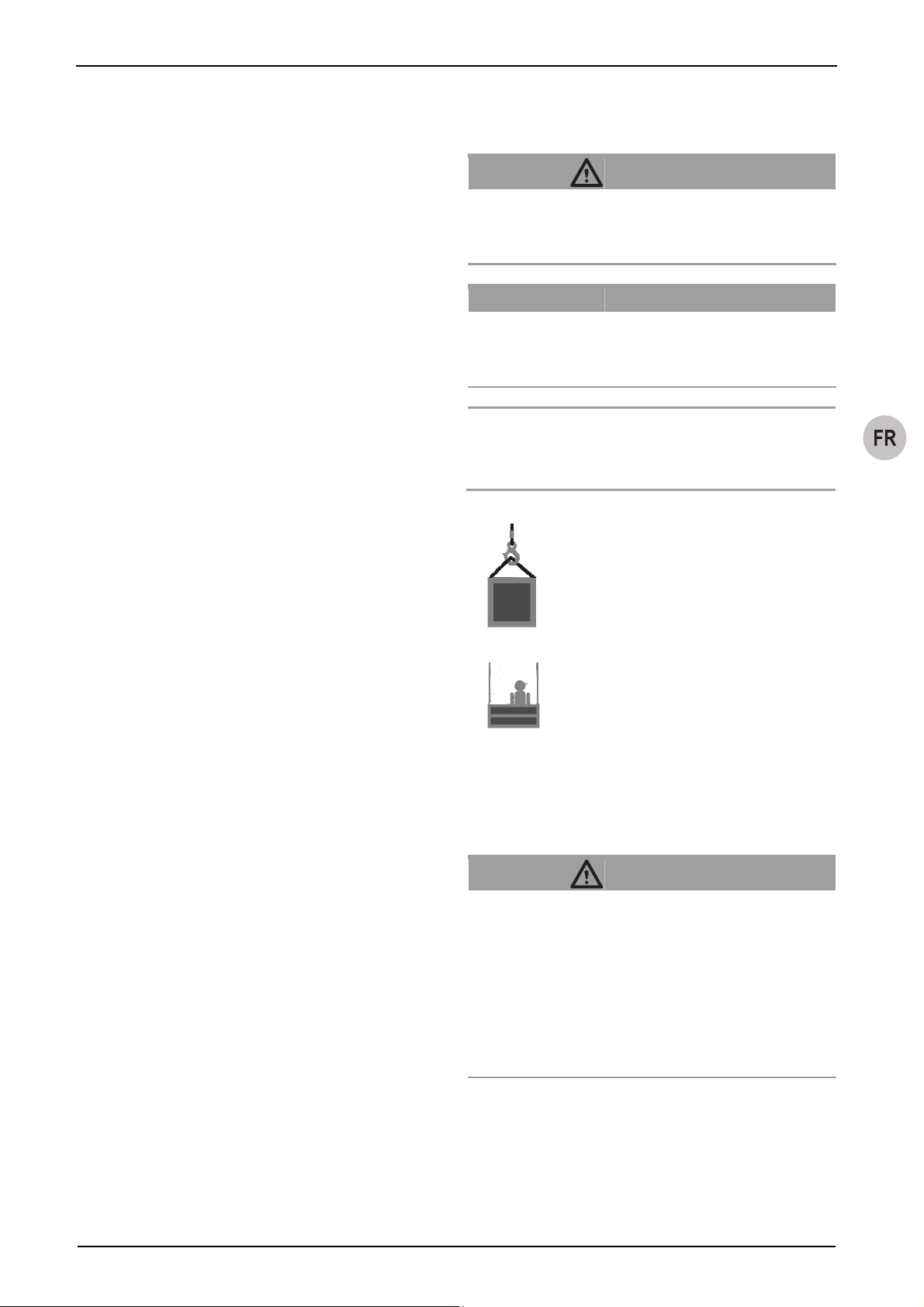
Dispositif antichute
Dispositif pour retenir des plates-formes pour du matériel, en cas
de rupture du câble porteur ou de dysfonctionnements, p. ex.
défaillance de l'entraînement des treuils.
Charge suspendue totale
La charge suspendue totale est la charge statique dont l'effort
s'exerce sur la suspension, composée de la charge utile, du
poids propre du moyen d'élingage, de l'équipement supplémentaire, des câbles métalliques et des câbles de commande et de
raccordement.
Engin de levage / Machine de levage des charges
Appareil ou équipement composé d'un appareil avec l'élément de
suspension des charges pour le levage ou le transport des charges (par exemple treuil ou treuil avec câble et crochet de levage
à émerillon).
Client/Client final
Le client ou le client final est le client du fabricant de l'installation
et peut aussi être simultanément l'exploitant.
Plates-formes de levage pour charges (PLC)
Une pièce ou élément d'équipement n'appartenant pas à la
machine, permettant la préhension de la charge, installé entre la
quasi-machine et la charge ou sur la charge ou destiné à devenir
partie intégrante de la charge. Sont également considérés plates-formes de levage les matériels d'élingage et leurs parties
constitutives.
Plates-formes de levage pour matériel (PFM)
Plates-formes de levage destinées au matériel.
Charge nominale
La charge nominale est la charge qui s'applique sur l'appareil. La
charge nominale maximale équivaut à la capacité de charge.
Plates-formes suspendues à niveau variable
Plates-formes destinées aux personnes. Comprend aussi les
combinaisons de plates-formes pour le matériel et les personnes.
Personne compétente
Une personne désignée et formée en conséquence, qui est
capable de par ses connaissances et son expérience pratique et
avec les instructions nécessaires, de réaliser les travaux requis.
Pièces au contact des câbles
Les pièces au contact des câbles sont les treuils, les poulies de
renvoi, les antichutes et autres dispositifs traversés par les câbles ou au contact des câbles.
Capacité de charge
La capacité de charge indique quelle est la charge ne devant pas
être dépassée sur l'appareil.
Elément de suspension des charges
Est considéré élément de suspension des charges tout équipement relié à l'engin de levage pour la préhension de la plateforme de levage, du matériel d'élingage ou de la charge (par
exemple un crochet solidaire du câble porteur).
Personnel de maintenance
Une personne désignée et formée par Greifzug Hebezeugbau
GmbH détenant un certificat valide, qui est capable, avec les
instructions nécessaires, de réaliser les travaux d’entretien, de
contrôle et de réparations requis.
Instructions de montage et d'utilisation
1.2 Symboles utilisés
DANGER !
Type et source du danger.
Conséquence : p. ex. blessures gravissimes ou mortelles.
– Mesures qui permettent d'éviter ce danger.
ATTENTION !
Type et source du danger.
Conséquence : p. ex. dommages matériels ou écologiques.
– Mesures qui permettent d'éviter ces dommages.
Indication :
Ce symbole n'indique pas des consignes de sécurité, mais
donne des informations pour mieux comprendre les opérations.
Ce symbole est destiné à marquer les appareils
pour le transport des matériaux.
Ce symbole est destiné à marquer les appareils
pour le transport des personnes et des matériaux.
2 Sécurité
2.1 Consignes de sécurité générales
DANGER !
Danger d'accident grave en cas de dysfonctionnements,
d'utilisation ou de manipulation incorrectes !
– Respecter les indications suivantes pour assurer une
utilisation en toute sécurité et un fonctionnement correct
de l'appareil !
– Respecter aussi les consignes de sécurité spéciales pour
les travaux qui doivent être exécutés mentionnées dans
les chapitres individuels de la présente notice
d’utilisation.
– Il ne faut pas utiliser de dispositifs antichutes, de câbles ou
d'élingues endommagés ou défectueux.
– N'utiliser les appareils qu'avec un câble d'origine d'un dia-
mètre indiqué dans la présente notice.
– Veiller à ce que le câble, le treuil, l’antichute et le matériel
d'élingage ne soient pas salis par les matériaux de cons-
G905.5 - 02/2011 FR-3
Page 50

Instructions de montage et d'utilisation
truction provoquant un encrassement notable tels que béton,
résine époxy ou autres agents adhésifs. Protéger les pièces
des impuretés ! Dans un environnement très encrassé, utiliser des brosses pour nettoyer le câble.
– Ne pas lubrifier le câble de sécurité avec des lubrifiants à
base de disulfure (p. ex. Molycote
®
).
– Respecter la date de mise au rebut du câble, voir
'16.3 Entretien et maintenance, Câble' page 16.
– Il est interdit de nettoyer le câble ou les dispositifs antichu-
tes avec un nettoyeur à haute pression ! La pénétration
d'humidité entraîne des dysfonctionnements.
– La saleté entraîne une usure prématurée du câble et détruit
celui-ci, les élingues et le dispositif antichute.
– Tenir compte des indications pour le transport, le stockage
et le nettoyage, à partir de la page 15.
– Respecter les fiches de données de sécurité concernant les
graisses utilisées du fabricant respectif.
– Les moyens de fixation doivent être conformes aux indica-
tions de cette notice et aux normes/directives en vigueur.
– Il ne faut pas dépasser la capacité de charge admise.
– Les travaux de réparation et d'entretien seront exécutés
uniquement par les personnes autorisées, cf.
'16.1 Personnel de maintenance autorisé' page 15.
– Il est interdit de réemployer les écrous autofreinés ; ils
doivent être changés.
– Le montage et la manipulation ne doivent être effectués que
par du personnel formé à cet effet en tenant compte de
cette notice.
– Le dispositif antichute doit être fixé de manière à ce que le
câble de sécurité entre verticalement par le haut dans le
dispositif antichute. Le dispositif antichute doit pouvoir être
aligné librement sur le câble de sécurité. Le câble de sécuri-
té doit être tendu par un poids de tension ou un enrouleur
adapté.
– Les travaux sur les équipements électriques ne doivent être
réalisés que par un électricien qualifié ou par des personnes
formées à cet effet, sous la direction et la surveillance d'un
électricien qualifié, conformément aux normes, réglementa-
tions et règles de l'électrotechnique.
– Ne pas se tenir sous des charges en suspension. Si néces-
saire, interdire l'accès à la zone dangereuse. Retenir la
charge qui s'est accrochée ou coincée et sécuriser.
– Ne pas saisir le câble pendant le fonctionnement.
– Pour les travaux de soudure, respecter les prescriptions
nationales de sécurité et de protection du travail (p. ex. en
Allemagne Règlement 159 de la Mutuelle professionnelle
BGR).
2.2 Indications pour l'exploitant
– L'exploitant est responsable de la fourniture d'instructions
d'utilisation, de maintenance, d'entretien et d'autres instructions de service claires, et doit assurer par la formation et
l'initiation du personnel, l'utilisation correcte et conforme à
l'emploi prévu, ainsi que la manipulation correcte de l'appareil.
– Les autocollants et les plaques d'avertissement seront
maintenus dans un état de lisibilité parfaite. Les autocollants
et les plaques d'avertissement manquants seront remplacés
immédiatement.
– L'exploitant est responsable du bon fonctionnement de
l'installation, ainsi que du respect des intervalles d'entretien,
et de la réalisation des travaux d'entretien.
– L'exploitant s'engage à tenir le journal de bord fourni.
– Dans l'Union Européenne, il faut appliquer la directive
89/391/CEE (en Allemagne le Décret sur la sécurité des ex-
ploitations (BetrSichV)). Il faut respecter les dispositions na-
tionales de protection au travail dans le pays concerné.
– Mettre des équipements de protection appropriés à disposi-
tion, tels que par ex. des gants de protection, une protection
auditive et un système antichute. La protection contre les
conditions météorologiques extrêmes (par ex. la protection
contre le soleil, contre le froid) fait partie de l’équipement de
protection individuelle.
– S’assurer que le poste de travail est toujours suffisamment
éclairé.
– La présente notice et les notices des pièces accessoires
seront remise au personnel en charge des travaux. Ces do-
cuments seront toujours tenus à portée de la main.
– Comme Greifzug Hebezeugbau GmbH ne sait pas comment
sera utilisée plus tard l'appareil décrit ici, l'exploitant est tenu
d'informer son personnel des autres consignes de sécurité,
ainsi que des travaux d'entretien complémentaires.
– L'exploitant de l'installation assume l'entière responsabilité
pour la méthode de fixation et l'adaptation des moyens
d'élingage.
– Les moyens de fixation doivent être conformes aux indica-
tions de cette notice et aux normes/directives en vigueur.
– Le fonctionnement sécurisé n'est pas assuré si des pièces
de rechange non originales sont utilisées. C'est le cas en
particulier pour l'utilisation de câbles qui ne sont pas homo-
logués d'origine tels qu'ils sont prescrits et destinés à l'ap-
plication en cause. Le droit de garantie à l'encontre du fabri-
cant devient alors caduc. Les produits ne portant pas la
marque CE perdent leur validité.
– Tenir compte de la plage de température admissible, cf.
Tableau 1 page II.
2.3 Responsabilité du fabricant de l'ins-
tallation
– Si plus d’une personne est chargée du travail décrit ici,
l'exploitant nommera un responsable de la surveillance
ayant pouvoir d’injonction.
– Le fabricant de l'installation est responsable du projet, de la
fabrication, du montage et de la mise en circulation, ainsi
que du marquage CE de l'installation, et de l'établissement
de la déclaration de conformité CE.
FR-4 G905.5 - 02/2011
Page 51

– Les produits figurant dans la livraison de Greifzug Hebe-
zeugbau GmbH doivent être sélectionnés soigneusement
par le fabricant de l'installation, utilisés conformément à
l'emploi prévu, et montés suivant les indications de la présente notice de montage et d'utilisation.
– Les assemblages vissés pour fixer le dispositif antichute et
le dispositif de serrage doivent être conçus suivant la configuration technique de la construction.
– Les informations et les indications de cette notice de mon-
tage et d'utilisation seront intégrées dans le manuel de service et la documentation du fabricant de l'installation, et
complétées par des informations spécifiques à l'installation
(p. ex. conduite à tenir en cas d'incidents et de blocage). Il
ne suffit pas de transmettre cette notice à l'exploitant.
– Les indications concernant l'entretien du produit et des
accessoires seront intégrées dans le carnet d'entretien de
l'installation.
3 Vue d'ensemble
3.1 Etat de livraison
A la livraison, le matériel est entièrement assemblé.
3.2 Produits fournis
y Antichute blocstop™ BSO
y Câble Tractel
mande
y Instructions de montage et d'utilisation d’origine
y Journal de bord
y Certificats de contrôle
y Déclaration de conformité CE
®
conformément aux spécifications de la com-
Instructions de montage et d'utilisation
N'utiliser le dispositif antichute qu'avec un câble d'origine ayant
un diamètre indiqué dans cette notice (voir également la plaque
signalétique).
A part le BSO 510, tous les appareils décrits ici peuvent être
utilisés comme dispositif antichute pour les monte-personnes et
monte-matériaux, cf. (Tableau 1 page II).
L'antichute BSO 510 est conçu uniquement pour retenir les
matériaux.
Les travaux de réparation et d'entretien seront exécutés uniquement par les personnes autorisées, cf. '16.1 Personnel de maintenance autorisé' page 15.
Greifzug Hebezeugbau GmbH déclare que la machine décrite
dans la présente notice satisfait aux consignes de sécurité technique qui s'imposent au fabricant de l'équipement à la date de
mise en circulation à l'intérieur de l'Union Européenne.
Il est interdit de mettre la quasi-machine en service avant que
l'installation dans laquelle elle sera incorporée soit conforme aux
dispositions de la Directive 2006/42/CE et à la législation nationale de transposition et que la déclaration de conformité afférente soit établie.
y L’exploitant ou le fabricant de l’installation est tenu de réali-
ser une évaluation des risques conformément à l'annexe I
de la directive 2006/42/CE. La norme EN 14492-1 doit être
prise en considération lors de la planification de l'installation.
y L’exploitant ou le fabricant de l’installation est tenu
d’exécuter une procédure d'évaluation de la conformité
conformément à l’article 12, alinéa 3 ou 4 de la directive
2006/42/CE sur les machines destinées au levage des per-
sonnes ou des personnes et des charges qui sont concer-
nées par l'annexe IV, n° 17 de la directive 2006/42/CE.
Respecter les normes EN 14492-1 et EN 1808 lors de la
planification de l'installation.
Ne pas monter le dispositif antichute dans des installations qui
doivent être conformes à la directive 95/16/CE (directive concernant les ascenseurs, en Allemagne : 12. GPSGV).
Produits en option :
y Eléments de jonction
Exclusions de garantie et de responsabilité
Cf. '13 Abus évident' page 14.
Toute utilisation divergeant des indications mentionnées ici est
3.3 Description de l'appareil
considérée interdite. Greifzug Hebezeugbau GmbH n'est pas
responsable des dommages qui en résulteraient. L'exploitant est
Utilisation normale
Le blocstop™ BSO avec système automatique en cas de vitesse
trop élevée, est un dispositif antichute qui peut être utilisé sur
n'importe quel engin de levage/monte-charge. L'appareil n'est
pas prévu pour une utilisation privée. L'utilisation exacte est fixée
par l'exploitant ou le fabricant de l'installation.
Conformément à la directive sur les machines 2006/42/CE,
annexe V, un dispositif antichute est un composant de sécurité.
Les composants de sécurité sont considérés comme des machines.
seul responsable des risques d'une utilisation interdite. L'utilisation normale comprend aussi l'observation de toutes les indications de la notice, en particulier des réglementations de montage
et de maintenance.
Domaine d'utilisation
L'appareil est adaptée pour les conditions d'exploitation suivantes :
y Pour installation fixes ou mobiles
y Pour utilisation à court terme
y A des altitudes maximales de 1000 m au-dessus du niveau
de la mer
G905.5 - 02/2011 FR-5
Page 52

Instructions de montage et d'utilisation
y Plage de température admissible, cf. Tableau 1 page II
DANGER !
Danger d'accident grave !
– Il est interdit de faire fonctionner le treuil 24 heures sur
24.
– Il est interdit d’utiliser le treuil dans les zones soumises à
des risques d'explosion.
– L'utilisation est interdite en atmosphère corrosive.
1)
– L'utilisation est interdite à proximité de la flamme nue ou
dans une atmosphère à température élevée.
1)
Protection anticorrosion conformément aux spécifications de la commande
Exemple de montage
Cf. 'Fig. 2.
1 Câble de sécurité 5 Treuil tirak™
2 Câble porteur 6 blocstop™ BSO
3 Déclencheur pour fins de
course
7 Poids de tension
Plaques signalétiques et panneaux
d’avertissement / Limites de l'utilisation
Cf. Fig. 4.
Rep. Désignation
1 Plaque signalétique blocstop™ BSO
2 Diamètre de câble
Vous trouverez les informations nécessaires sur la plaque signalétique.
Directives et normes
Directives et normes ayant été appliquées : cf. '10.1 Directives et
normes' page 8.
Versions de produits dans la notice
La présente notice décrit les modèles de produits indiqués
Tableau 1 page II.
4 Fin de course "Montée"
Configuration de la construction sur le site
La capacité de charge nécessaire est obtenue en multipliant la
charge nominale maximale par le coefficient de fonctionnement.
La capacité de charge des équipements de construction pour la
fixation du produits, des élingues et des câbles doit correspondre
au moins à la charge nominale multipliée par le coefficient de
fonctionnement :
Dispositif antichute : coefficient de fonctionnement = 5
La construction de suspension installée par le client pour câbles
et produits doit être conçue conformément à la directive
006/42/CE et aux normes en vigueur telles que la norme EN
1808).
Pour des monte-personnes et une fixation sur des constructions
fixes, la construction doit être conçue de manière à ce que le
facteur de choc soit inférieur à 3 (cf. EN 1808, 6.5.3.6). Cela est
nécessaire pour satisfaire à la charge dynamique en cas de
chute.
Les cotes de montage des différents modèles se trouvent au
Tableau 2 page IV.
Le câble, les pièces au contact du câble et le matériel d'élingage
ne doivent pas être salis par des matériaux de construction
encrassés tels que béton, résine époxy ou autres agents adhésifs. Protéger l'appareil contre l'encrassement ! Dans un environnement très encrassé, utiliser des brosses pour nettoyer le câble.
4 Description
4.1 Description du fonctionnement
Le dispositif antichute contrôle la vitesse du monte-charge. Si la
vitesse est trop rapide, l'antichute arrête la descente du montecharge par solidarisation (blocage) au câble de sécurité.
Le dispositif antichute fonctionne automatiquement. La vitesse
du câble de sécurité est contrôlée en permanence par un poids
centrifuge.
En cas de vitesse trop élevée, le poids centrifuge déclenchent
les mâchoires qui retiennent la charge par le câble de sécurité et
fonctionnent par blocage automatique : si la charge se déplace
dans le sens opposé à la montée, les mâchoires se ferment
automatiquement. Plus la force de traction est importante, plus
l'effet de blocage est fort.
Cf. Fig. 12.
Lors du montage de l'antichute, tenir compte de la direction vers
laquelle s'accélère le câble de sécurité ou l'antichute, par ex. en
cas de rupture du câble porteur, de façon à déclencher l'impulsion arrêtant le câble.
Le sens de freinage (B) correspond à la direction dans laquelle
l'antichute arrête l'extrémité de câble avec la charge. Le sens de
passage de câble (A) correspond à la direction dans laquelle le
câble traverse l'antichute, que
y l'antichute soit fixée à un porteur ou à un composant, qu'elle
monte ou descende sur un câble fixé ou
y que le câble se déplace, par ex. , à travers un antichute fixé
par le client.
FR-6 G905.5 - 02/2011
Page 53
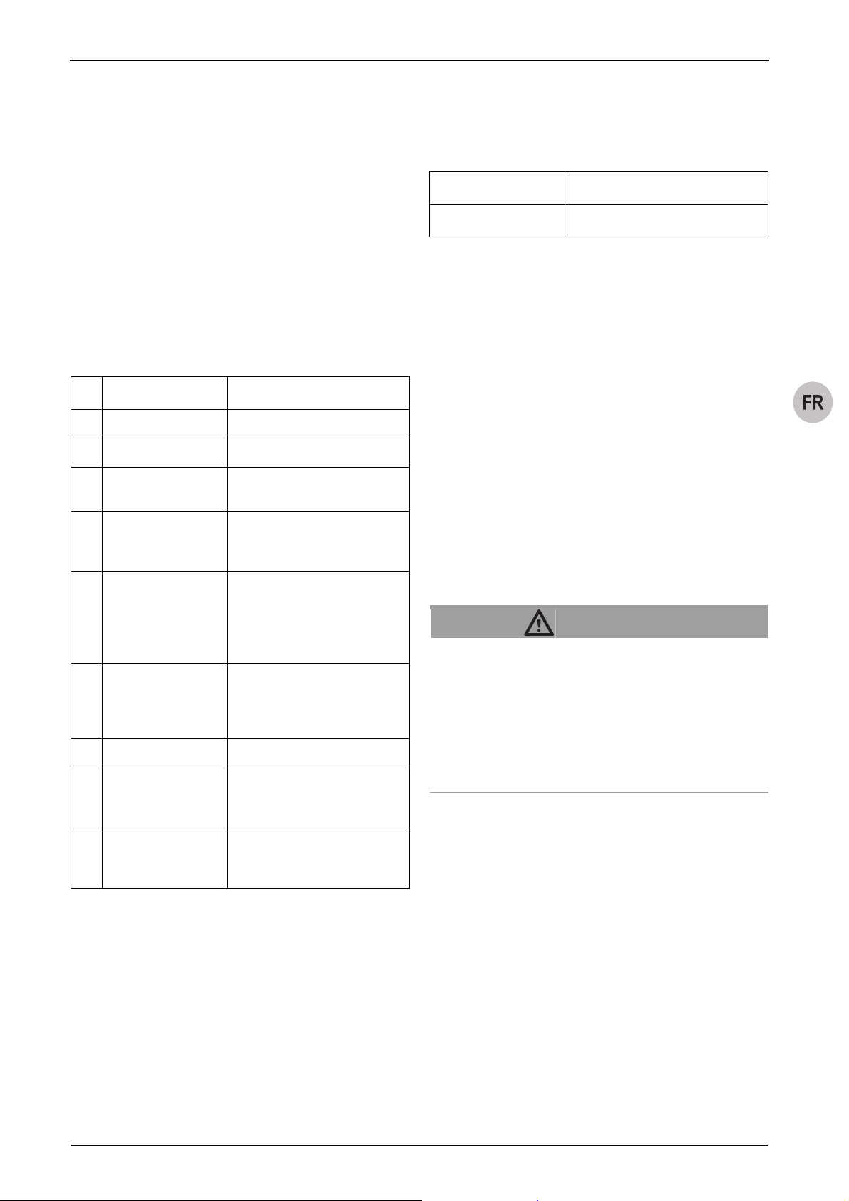
Monter le dispositif antichute de manière à ce que le sens (A)
dans lequel le câble traverse l'antichute au moment de la défaillance, soit contraire au sens de freinage (B).
Ainsi, l'engin de levage/le monte-charge sont protégés contre les
dommages suivants :
y la rupture du câble porteur,
y la défaillance du treuil (rupture d'engrenage).
En cas d’urgence, le dispositif antichute peut être déclenché à la
main en appuyant sur la touche ARRET D'URGENCE.
Instructions de montage et d'utilisation
4.4 Consommables
Lubrifiants
Utilisation Lubrifiants
Câble Huile/graisse multi-usage (sans disulfure)
4.5 Schéma de circuits
4.2 Composants/Modules
Cf. Fig. 1.
Rep. Désignation Fonction
1 Câble de sécurité
2 Levier Valider le dispositif antichute
3 Touche d’ARRET
D’URGENCE
Déclenchement manuel du dispositif
antichute
4 Fenêtre de contrôle Contrôle visuel du fonctionnement
du mécanisme à force centrifuge
pendant le fonctionnement
5 Poids centrifuge Contrôle en permanence pendant le
déplacement la vitesse du câble. Si
la vitesse réglée est dépassée, il
déclenche le mécanisme des mâchoires.
6 Mâchoires Jonction mécanique du câble en cas
de chute et de déclenchement. Plus
la force de traction est importante,
plus l'effet de blocage est fort.
7 Fin de course En option
8 Trou de fixation Logement pour les boulons/vis pour
fixer le dispositif antichute au moyen
de fixation
9 Pointe de contrôle Uniquement BSO 2050/2360 : visible
lorsque le câble de sécurité est
introduit correctement.
4.3 Caractéristiques techniques
Vous trouverez les caractéristiques techniques dans Tableau 1
page II.
Le schéma de circuits du treuil se trouve dans la boîte à bornes
du moteur.
Cf. '10.3 Montage, Antichute avec fin de course : Raccordement
électrique page 10.
4.6 Equipements de sécurité
En cas d’urgence, le dispositif antichute peut être déclenché à la
main en appuyant sur la touche ARRET D'URGENCE.
En option sur les antichutes avec déconnexion électrique :
En cas de chute, l'interrupteur de fin de course permet de couper
le courant pour la descente.
4.7 Fixation
DANGER !
Danger d'accident grave à cause d'une fixation non
conforme !
Les boulons galvanisés haute résistance peuvent devenir
cassants et rompre. Risque chute de l'installation et de blessure de chute d'objets !
– Pour la fixation, il est interdit d'utiliser des boulons galva-
nisés haute résistance (10.9 et 12.9).
– Utiliser des boulons présentant une résistance suffisante.
Vous trouverez les informations sur la résistance des boulons
Tableau 1 page II.
Respecter les indications de 'Configuration de la construction sur
le site' page 6.
Le dispositif antichute doit être fixé de manière à ce que le câble
de sécurité entre verticalement par le haut dans le dispositif
antichute. Le dispositif antichute doit pouvoir être aligné librement sur le câble de sécurité. Le câble de sécurité doit être
tendu par un poids de tension ou un enrouleur adapté.
La capacité de charge nécessaire de la suspension et des pièces
de fixation dépend du modèle du dispositif antichute.
G905.5 - 02/2011 FR-7
Page 54

Instructions de montage et d'utilisation
5 Câbles
Généralités
DANGER !
Câble ou diamètre de câble non conformes !
L’utilisation d'un câble non conforme constitue un risque de
chute, de blessure par chute d'objets et un risque de dysfonctionnements !
– Pour assurer le bon fonctionnement, utiliser uniquement
un câble d’origine homologué par Greifzug Hebezeugbau
GmbH d’un diamètre approprié et de type prescrit.
Vous trouverez le diamètre de câble nécessaire Tableau 1
page II. Information sur le modèle Tableau 3 page 16.
Autre configuration admissible des câbles :
y Extrémité / cosse
y Extrémité / crochet de sécurité
6 Accessoires en option
y Possibilités de fixation, par ex. jeux d'éclisses
7 Options
Les modèles d'antichute décrits ici sont disponibles en option
avec les fins de course (p. ex. blocstop™ BSO 2030 E).
Veuillez vous adresser pour cela directement à Greifzug Hebezeugbau GmbH.
8 Versions de modèle
10 Installation et mise en service
10.1 Directives et normes
Le dispositif antichute satisfait aux directives et normes suivantes :
y Directive sur les machines 2006/42/CE
y DIN EN ISO 12100
y Machines destinées au levage des personnes et des char-
ges (transport des personnes) :
EN 1808:1999 + A1:2010
En plus, pour les installations avec antichute :
y Les buts en matière de protection de la Directive
2006/95/CE sont respectés conformément à l'Annexe I n°
1.5 de la Directive 2006/42/CE.
L'exploitant ou le fabricant de l’installation endosse la responsabilité de l'utilisation de la quasi-machine dans les limites indiquées dans la présente notice. L'exploitant ou le fabricant de
l'installation doivent aussi s'assurer que la machine dans laquelle
la quasi-machine est intégrée satisfait aux directives et normes
ci-dessus, à EN ISO 14121 et à EN ISO 13849.
10.2 Contrôles avant de commencer le
montage
Contrôle de la construction portante
La construction de suspension installée par le client pour câbles
et produits doit être conçue conformément à la directive
006/42/CE et aux normes en vigueur telles que la norme EN
1808).
Respecter les indications de 'Configuration de la construction sur
le site' page 6.
La vitesse de déroulement standard des dispositifs antichutes
décrits ici est de 30 m/min. Des modèles d'une vitesse de déroulement de 20, 40, 60 ou 70 m/min sont disponibles aussi sur
demande.
Contrôle de l'emplacement de montage
– S'assurer que le montage conforme du châssis de roule-
ment n'est pas gêné par d'autres éléments.
Aucune pièce pointue ou tranchante ne doit se trouver dans
le logement.
9 Accessoires nécessaires
– Contrôler que les plaques signalétiques ne sont pas recou-
vertes par la fixation (cf. Fig. 4.
Pour pouvoir utiliser l'appareil, vous avez besoin des accessoires
suivants qui ne figurent pas dans la livraison :
y Câble Tractel d'origine
®
y Dispositif tendeur (poids) pour le câble, voir Fig. 6
L'exploitant ou le fabricant de l’installation est responsable de la
sélection et de l'utilisation des accessoires conformément aux
conditions locales. Il convient de respecter les autres spécifications indiquées dans les normes et directives respectivement en
vigueur.
– Le dispositif antichute doit être fixé de manière à ce que le
câble de sécurité entre verticalement par le haut dans le
dispositif antichute. Le dispositif antichute doit pouvoir être
aligné librement sur le câble de sécurité. Le câble de sécuri-
té doit être tendu par un poids de tension ou un enrouleur
adapté.
– Le dispositif antichute doit être installé de manière à ce que
l'opérateur puisse déclencher en tout temps la touche
d'ARRET D'URGENCE et contrôler le fonctionnement dans
la fenêtre de contrôle. Exemples de montage : avec un
monte-personnes, par ex. sur une plate-forme de travail,
FR-8 G905.5 - 02/2011
Page 55

avec un monte-matériaux par ex. à l'emplacement de l'opérateur.
Cf. Fig. 12.
Monter le dispositif antichute de manière à ce que le sens (A)
dans lequel le câble traverse l'antichute au moment de la défaillance, soit contraire au sens de freinage (B).
Pour les dispositifs antichutes avec fins de course :
y Possibilité de raccordement au boîtier de commande du
treuil
Contrôle du dispositif antichute et des accessoires
Instructions de montage et d'utilisation
10.3 Montage
Conditions
y Le montage ne doit être effectué que par du personnel
formé.
y Le poste de travail doit être suffisamment éclairé.
y L'écart entre le câble de sécurité et le câble porteur doit être
aussi petit que possible.
y Position de la pièce de fixation :
L'écart entre les pièces de fixation et le treuil doit être sélec-
tionné de manière à ce que le câble de sécurité rentre verti-
calement dans l'ouverture du BSO.
Dispositif antichute
– Vérifier que le boîtier n'est pas endommagé.
Essayer la touche d’ARRET D’URGENCE :
– Déclencher l'antichute en appuyant sur la touche d'ARRET
D'URGENCE.
Un déclic doit être perceptible à la fermeture.
Câble
– S'assurer que le diamètre et le type de câble présentent
toute conformité pour l'appareil et l'application. Cf.
Tableau 1 page II, Tableau 3 page 16 et 'Plaques signalétiques et panneaux d’avertissement / Limites de l'utilisation'
page 6.
– S’assurer que le câble a une longueur suffisante :
La charge doit pouvoir être déplacée en toute sécurité jusqu'à la position initiale et la position finale.
Pour le dispositif de serrage, il faut au moins 3 m de l'extrémité du câble.
– S'assurer que la cosse (1) et la garniture de pression (2)
sont en parfait état (cf.Fig. 5).
– Câble avec crochet :
S'assurer que le crochet et le clapet de sécurité (3) sont en
parfait état, cf. Fig. 5.
– Vérifier l’absence de dommages visibles sur toute la lon-
gueur du câble, cf. Fig. 7.
– Contrôler en conséquence l’extrémité du câble Fig. 9 (cf.
aussi '16.3 Entretien et maintenance, Câble' page 16).
Moyens de fixation
– S'assurer que les boulons, les vis et le matériel d'élingage
sont conformes aux prescriptions '4.7 Fixation' page 7.
– S'assurer que les brides, les broches d'arrimage et les
assemblages vissés ne sont pas endommagés.
Monter le dispositif antichute
DANGER !
Danger d'accident grave à cause d'une fixation non
conforme !
Les boulons galvanisés haute résistance peuvent devenir
cassants et rompre. Risque chute de l'installation et de blessure de chute d'objets !
– Pour la fixation, il est interdit d'utiliser des boulons galva-
nisés haute résistance (10.9 et 12.9).
– Utiliser des boulons présentant une résistance suffisante.
Danger d'accident grave à cause d'une fixation non
conforme !
Risque de chute de l'installation et de blessure par chute
d'objets !
– blocstop™ BSO 2050 et 2360 doivent être fixés dans les
deux trous des pièces de fixation.
– Les pièces de fixation doivent être munies de deux éclis-
ses ou pièces similaires.
Selon l'application, tenir compte de la direction de l'effort du
dispositif antichute lors du montage (cf. aussi Fig. 12 et
'4.1 Description du fonctionnement' page 6).
– Fixer le dispositif antichute à la pièce de fixation.
BSO 500 - BSO 1040 : 1 boulon ou 1 vis
Série BSO 2050, Serie BSO 2360 : 2 boulons ou 2 vis
– Bloquer les boulons avec une clavette ou une sécurité
similaire.
– Bloquer les vis avec des écrous autobloquants pour ne pas
les perdre.
G905.5 - 02/2011 FR-9
Page 56

Instructions de montage et d'utilisation
Installer le câble de sécurité
DANGER !
Risque de blessure lié à des piqûres et des coupures !
Des ruptures de fil dans le câble métallique peuvent faire
dépasser les fils. Les fils saillants peuvent couper ou piquer à
travers les gants de protection !
– Porter des gants de protection en cuir lourds et appro-
priés pour les travaux sur le câble métallique.
– Ne pas faire glisser le câble métallique entre les mains.
Danger d'accident grave suite à une fixation non
conforme !
Risque de dysfonctionnement si l'antichute ne peut pas être
équilibré sur le câble.
– Le dispositif antichute doit être fixé de manière à ce que
le câble de sécurité entre verticalement par le haut dans
le dispositif antichute.
– Le dispositif antichute doit pouvoir être aligné librement
sur le câble de sécurité.
– Le câble de sécurité doit être tendu par un poids de
tension ou un enrouleur approprié.
ATTENTION !
Montage incorrect !
Risque de dommage du câble !
– Ne pas faire passer le câble sur les arêtes.
– Laisser pendre l’extrémité du câble.
Nota
Ne pas confondre câble de sécurité et câble porteur : respecter
le bon diamètre du câble (cf. aussi Fig. 4).
Cf. Fig. 11.
Schéma de raccord des antichutes et fins de course.
L'interrupteur doit être raccordé comme contact à ouverture pour
permettre une déconnexion forcée.
– Utiliser les couleurs BK (noir = black) et BKWH (noir et
blanc = blac-white) pour le raccordement.
Câble du fin de course avec connecteur
– Raccorder le câble du fin de course au boîtier de com-
mande du treuil.
Connexion fixe
Seul un électricien qualifié est habilité à exécuter ce travail.
– Raccorder le câble du fin de course suivant le plan de câ-
blage au boîtier de commande du treuil.
10.4 Mise en service
Etablir la disponibilité
– Contrôler la fixation du câble.
– Contrôler la liaison entre l'antichute et la plate-forme.
– Contrôler que le câble rentre verticalement dans le dispositif
antichute.
– Contrôler que le dispositif antichute peut être aligné libre-
ment sur le câble de sécurité.
– Noter les résultats du contrôle dans le journal de bord.
Essai de fonctionnement
Cf. 'Fig. 10 (exemple).
– Dérouler le câble à l’horizontale pour qu’il n’y ait pas de
boucles.
– Fixer le câble à la construction portante. Le câble doit pen-
dre librement.
– Ouvrir l'antichute en appuyant sur le levier.
– Introduire le câble par le haut.
BSO 2050/2360 : lorsque le câble est rentré correctement,
la pointe de contrôle ressort.
– Tirer le câble à la main pour le tendre.
– Fixer deux poids tendeurs d'environ 11,5 kg chacun, à env.
20 cm au-dessus du sol (cf. Fig. 6).
– Déposer correctement l'extrémité du câble pour qu'il n'y ait
pas de boucles ni de nœuds.
Antichute avec fin de course : Raccordement
électrique
En cas de chute, l'interrupteur de fin de course permet de couper
le courant pour la descente.
Contrôle général de fonctionnement :
– Vérifier que le boîtier n'est pas endommagé.
– Appuyer sur la touche d’ARRET D’URGENCE (1) pendant
la descente.
L'antichute doit fermer et tenir le câble prisonnier.
En option sur antichutes avec fin de course :
Le treuil ne doit pas descendre.
– Ouvrir l'antichute : tourner la manivelle (2) dans le sens des
aiguilles d'une montre jusqu'à ce qu'il encastre.
Vérifier le fonctionnement du poids centrifuge :
– Pendant tout déplacement, vérifier au moins une fois sur la
fenêtre de contrôle (4) que le poids centrifuge tourne.
Vérifier le déclenchement de l'antichute :
La fonction de limitation de vitesse peut être contrôlée à l'aide de
deux tests différents. La méthode de contrôle dépend des conditions de montage de l'antichute.
FR-10 G905.5 - 02/2011
Page 57
y Méthode 1 : démonter l'antichute, le soulever d'env. 30 cm
et le laisser retomber le long du câble (vertical). Il ne doit
pas y avoir de pièces du client sur le trajet de chute, sus-
ceptibles d'être heurtées par le dispositif antichute.
y Méthode 2 : Passer le câble de sécurité à travers le disposi-
tif antichute en tirant d'une main d'un coup sec.
Méthode 1 (contrôle de la limitation de vitesse) :
DANGER !
Risque de blessure par chute d'objets ! Risque d'écrasement et de cisaillement !
Pour le contrôle suivant, il y a risque d'écrasement et de
cisaillement entre le dispositif antichute qui tombe et les pièces installées par le client.
– Ne pas introduire la main dans la trajectoire de chute du
dispositif.
Risque de blessure par chute d'objets ! Risque d'écrasement et de cisaillement !
Si le dispositif antichute ne déclenche pas et qu'il n'y a pas de
pièces limitant le trajet de chute, le dispositif peut tomber de
façon incontrôlée et mettre en danger d'autres personnes.
– Limiter le trajet de chute ou prendre des mesures appro-
priées !
ATTENTION !
Risque d'endommager le dispositif antichute ou d'autres
pièces !
Pour le contrôle suivant, le dispositif antichute peut heurter les
pièces installées par le client et être endommagé.
– Veiller à ce que le dispositif antichute ne puisse pas
heurter les pièces fixées par le client.
– Si une collision ne peut être excluse, effectuer le contrôle
avec l'autre méthode.
– Enlever la fixation du dispositif antichute (par ex. les bou-
lons (3) indiqués dans l'exemple de montage décrit).
– Monter l'antichute d'env. 30 cm le long du câble.
– Laisser retomber l'antichute :
Celui-ci doit fermer au bout de maximum 8 cm et être soli-
dement accroché au câble.
– Ouvrir l'antichute : tourner la manivelle (2) dans le sens des
aiguilles d'une montre jusqu'à ce qu'il encastre.
– Faire descendre le dispositif antichute le long du câble.
– Monter le dispositif antichute :
Bloquer le boulon avec une nouvelle goupille.
Bloquer les vis avec un nouvel écrou autobloquant.
Instructions de montage et d'utilisation
Méthode 2 (contrôle de la limitation de vitesse) :
Cf. Fig. 12.
– Enlever le poids tendeur du câble de sécurité ou former une
boucle de câble sur l'extrémité (extrémité sans charge sur
l'antichute).
– Tirer brusquement le câble dans la direction 'A'.
L'antichute doit fermer et tenir le câble prisonnier.
– Ouvrir l'antichute : tourner la manivelle (2) dans le sens des
aiguilles d'une montre jusqu'à ce qu'il encastre.
– Si nécessaire, retendre le câble de sécurité en le tirant à la
main.
– Le cas échéant, attacher à nouveau le poids tendeur au
câble de sécurité.
11 Fonctionnement et service
L'opérateur doit être formé par l'exploitant pour pouvoir utiliser
l'appareil, et doit être familiarisé avec son utilisation.
11.1 Contrôles avant de commencer le
travail
– Contrôler l’absence d'encrassements tenaces sur le câble,
le nettoyer éventuellement.
– S'assurer de la disponibilité, cf. '10.4 Mise en service,
Etablir la disponibilité' page 10.
– Faire un essai de fonctionnement, cf. '10.4 Mise en service,
Essai de fonctionnement' page 10.
– Noter les résultats du contrôle dans le journal de bord.
11.2 Fonctionnement avec un montepersonnes
DANGER !
Danger de blessure lié à une trop grande hauteur de
chute !
Lors de la montée avec le dispositif antichute fermé, le câble
de sécurité est poussé vers le haut et n'est plus tendu entre la
suspension et l'antichute !
– Avant tout déplacement, s'assurer que le levier est sur
OUVERT et enclenché.
Cf. 'Fig. 10 (exemple).
– Ouvrir l'antichute : tourner la manivelle (2) dans le sens des
aiguilles d'une montre jusqu'à ce qu'il encastre.
– Démarrer l'engin de levage.
– Pendant tout déplacement, vérifier au moins une fois sur la
fenêtre de contrôle (4) que le poids centrifuge tourne.
G905.5 - 02/2011 FR-11
Page 58

Instructions de montage et d'utilisation
Remarque :
Effectuer ce contrôle, si possible au début du déplacement,
avant que le monte-charge ait atteint une grande hauteur.
Si le poids centrifuge ne tourne pas :
– Arrêter immédiatement le monte-charge.
– Respecter le plan d'urgence de l'exploitant.
– Démonter l'antichute et l'envoyer pour contrôle à Greifzug
Hebezeugbau GmbH ou à un atelier agréé pour engins de
levage.
Le câble de sécurité n'est pas tendu
Quand le dispositif antichute est fermé, cela signifie que le câble
de sécurité s'est détendu :
– Arrêter l'engin de levage.
– Contrôler si le câble pend librement.
– Ouvrir l'antichute : tourner la manivelle (2) dans le sens des
aiguilles d'une montre jusqu'à ce qu'il encastre.
– Si nécessaire, retendre le câble de sécurité en le tirant à la
main.
– Ne continuer le déplacement que lorsque le câble de sécuri-
té est de nouveau tendu.
11.3 Fonctionnement avec un montematériaux
Cf. 'Fig. 10 (exemple).
– Ouvrir l'antichute : tourner la manivelle (2) dans le sens des
aiguilles d'une montre jusqu'à ce qu'il encastre.
– Démarrer l'engin de levage.
– Pendant tout déplacement, vérifier au moins une fois sur la
fenêtre de contrôle (4) que le poids centrifuge tourne.
Si le poids centrifuge ne tourne pas :
– Arrêter immédiatement le monte-charge.
– Démonter l'antichute et l'envoyer pour contrôle à Greifzug
Hebezeugbau GmbH ou à un atelier agréé pour engins de
levage.
– Ne continuer le déplacement que lorsque le câble de sécuri-
té est de nouveau tendu.
11.4 ARRET D’URGENCE manuel
En cas d’urgence, le dispositif antichute peut être déclenché à la
main en appuyant sur la touche ARRET D'URGENCE.
11.5 Blocage de la charge
En cas d'interruptions de travail, il est possible d'utiliser le dispositif antichute pour bloquer la charge. Cela permet par ex. de
soulager l'engrenage du treuil.
Remarque :
– Tenir compte des instructions de travail et des mesures de
sécurité de l'exploitant et des indications des notices d'utilisation concernant les engins de levage ou les montecharges.
Cf. 'Fig. 10 (exemple).
Bloquer la charge :
– Déclencher l'antichute en appuyant sur la touche d'ARRET
D'URGENCE.
Rouvrir l'antichute :
– Monter sur une faible distance pour soulager le câble.
– Ouvrir l'antichute : tourner la manivelle (2) dans le sens des
aiguilles d'une montre jusqu'à ce qu'il encastre.
– Si nécessaire, retendre le câble de sécurité en le tirant à la
main.
– Ne continuer le déplacement que lorsque le câble de sécuri-
té est de nouveau tendu.
12 Mesures à prendre immédiate-
ment en cas de chute
Une chute signifie déclenchement du dispositif antichute, par
ex. en cas de rupture de l'engrenage du treuil ou du câble porteur.
Le câble de sécurité n'est pas tendu
12.1 Antichute pour les monte-personnes
Quand le dispositif antichute est fermé, cela signifie que le câble
de sécurité s'est détendu :
DANGER !
– Arrêter l'engin de levage.
– Contrôler si le câble pend librement.
– Ouvrir l'antichute : tourner la manivelle (2) dans le sens des
aiguilles d'une montre jusqu'à ce qu'il encastre.
– Si nécessaire, retendre le câble de sécurité en le tirant à la
main.
Danger d'accident grave à cause d'un comportement
inadapté !
– Rester calme.
– Contrôler la cause.
– Supprimer le défaut.
FR-12 G905.5 - 02/2011
Page 59

Si un câble porteur a cassé ou s'il y a une défaillance de l'engin
de levage :
– Déclencher l'évacuation de l'équipage. Cf. documentation
du monte-personnes ou, si existant, le plan de sauvetage en
cas d'urgence de l'exploitant.
– Bloquer le monte-personnes en adoptant des mesures
appropriées pour pouvoir changer le câble porteur ou l'engin
de levage.
– Fixer le câble de sécurité au sol.
Si l'on peut exclure une rupture du câble porteur ou une défaillance de l'engin de levage :
– Essayer de monter.
Si ce n'est pas possible :
– Evacuer l'équipage et bloquer le monte-personnes (cf. ci-
dessus).
Cf. Fig. 10.
S'il est possible de monter, il s'agit probablement d'un défaut de
l'antichute.
– Monter sur une faible distance pour soulager le câble.
– Ouvrir l'antichute : tourner la manivelle (2) dans le sens des
aiguilles d'une montre jusqu'à ce qu'il encastre.
– Si nécessaire, retendre le câble de sécurité en le tirant à la
main.
– Descendre.
– Appuyer sur la touche d’ARRET D’URGENCE (1) pendant
la descente.
Antichute sans fin de course :
– Descendre jusqu'à ce que la charge soit retenue avec l'anti-
chute au câble de sécurité.
Antichute avec fin de course :
– Effectuer la descente de secours (cf. documentation du
treuil ou du monte-personnes) jusqu'à ce que la charge soit
retenue avec l'antichute au câble de sécurité.
Lorsque la charge n'est pas maintenue :
– Evacuer l'équipage et bloquer le monte-personnes (cf. ci-
dessus).
Lorsque la charge est maintenue :
– Monter sur une faible distance pour soulager le câble.
– Ouvrir l'antichute : tourner la manivelle (2) dans le sens des
aiguilles d'une montre jusqu'à ce qu'il encastre.
– Descendre lentement avec précaution la plate-forme, tout
en étant prêt à tout moment à appuyer sur la touche d'AR-
RET D'URGENCE de l'antichute.
Après une chute :
Cf. '12.3 Mesures à prendre après une panne ou une chute'
page 14.
Instructions de montage et d'utilisation
12.2 Antichute pour les monte-matériaux
DANGER !
Danger de blessure par la chute de charge !
– Il est interdit de prendre place sous la plate-forme du
matériel.
– Contrôler la cause de la panne.
– Supprimer le défaut.
Si un câble porteur a cassé ou s'il y a une défaillance de l'engin
de levage :
– Bloquer le monte-charge en adoptant des mesures appro-
priées pour pouvoir changer le câble porteur ou l'engin de
levage.
Si l'on peut exclure une rupture du câble porteur ou une défaillance de l'engin de levage :
– Essayer de monter.
Si ce n'est pas possible :
– Sécuriser la plate-forme du matériel (cf. ci-dessus).
Cf. Fig. 10.
S'il est possible de monter, il s'agit probablement d'un défaut de
l'antichute.
– Monter sur une faible distance pour soulager le câble.
– Ouvrir l'antichute : tourner la manivelle (2) dans le sens des
aiguilles d'une montre jusqu'à ce qu'il encastre.
– Si nécessaire, retendre le câble de sécurité en le tirant à la
main.
– Descendre.
– Appuyer sur la touche d’ARRET D’URGENCE (1) pendant
la descente.
Lorsque la charge n'est pas maintenue :
– Bloquer le monte-charge par des mesures appropriées.
Lorsque la charge est maintenue :
– Monter sur une faible distance pour soulager le câble.
– Ouvrir l'antichute : tourner la manivelle (2) dans le sens des
aiguilles d'une montre jusqu'à ce qu'il encastre.
– Descendre lentement avec précaution la plate-forme, tout
en étant prêt à tout moment à appuyer sur la touche d'AR-
RET D'URGENCE de l'antichute.
Après une chute :
Cf. '12.3 Mesures à prendre après une panne ou une chute'
page 14.
G905.5 - 02/2011 FR-13
Page 60

Instructions de montage et d'utilisation
12.3 Mesures à prendre après une panne
ou une chute
DANGER !
Risque d'accident grave !
En cas de chute, toute la construction est sollicitée par l'effort
intervenant brusquement. Risque de dommages de la construction de suspension, des moyens de fixation, du câble et
de l'antichute.
– L'antichute doit être contrôlé par Greifzug Hebezeugbau
GmbH ou par un atelier agréé pour engins de levage.
– Une personne compétente doit réaliser le contrôle sur le
lieu d'intervention.
– Démonter l'antichute et l'envoyer pour contrôle à Greifzug
Hebezeugbau GmbH ou à un atelier agréé pour engins de
levage.
Contrôle par une personne compétente sur le site :
y Câble de sécurité
y Fixation du câble de sécurité
y point de fixation de l'antichute et point de fixation de la
plate-forme sur l'installation du client
y tous les boulons et les assemblages vissés
Un contrôle n'est pas nécessaire après ce type de déclenchement.
13 Abus évident
Les droits à la garantie et de responsabilité en cas de dommages
corporels ou matériels sont exclus, s'ils proviennent de l'une ou
de plusieurs raisons suivantes :
y Utilisation non conforme de l'appareil, des accessoires ou
d'éléments de suspension des charges appartenant à l'appareil
y BSO 510: Transport de personnes.
y Fonctionnement avec un câble encrassé.
y Exploitation en atmosphère explosible ou corrosive.
y L'entretien n'a pas été effectué aux intervalles prescrits.
y Nettoyage avec un nettoyeur à haute pression.
y Montage, mise en service, utilisation, entretien et réparation
non conformes.
y Exploitation avec un branchement électrique qui ne corres-
pond pas aux spécifications de la présente notice
y Contrôle insuffisant des pièces de l'appareil ou des acces-
soires qui sont soumis à l'usure.
y Réparations non conformes, effectuées par une personne
non autorisée.
y Utilisation de pièces de rechange qui ne sont pas d'origine.
y Modification des réglages des équipements de sécurité.
y Omission des mesures et contrôles pour la détection des
dommages en temps utile.
y Surcharge de l'appareil
y Blocage/Calage du levier
y Accident provoqué par un corps étranger et cas de force
majeure.
y Le fabricant n'endosse aucune responsabilité pour les
dommages provenant de conversions et de modifications ou
de l'utilisation de pièces non originales, sans autorisation
écrite explicite de celui-ci.
y Il est interdit d'utiliser des appareils défectueux et endom-
magés ; il est interdit de rapporter des pièces accessoires et
des moyens d'élingage.
y Elingage du câble de sécurité sur le même point que le
câble porteur.
y Levage avec un câble de sécurité qui a pris du mou.
y Utilisation d'un monte-personnes avec un engin de levage
dont la vitesse du câble est supérieure à 18 m/min
Pour le transport des personnes :
y Utilisation de l'antichute sur le câble porteur.
14 Démontage
DANGER !
Risque de blessure lié à des piqûres et des coupures !
Des ruptures de fil dans le câble métallique peuvent faire
dépasser les fils. Les fils saillants peuvent couper ou piquer à
travers les gants de protection !
– Porter des gants de protection en cuir lourds et appro-
priés pour les travaux sur le câble métallique.
– Ne pas faire glisser le câble métallique entre les mains.
– Enlever les poids tendeurs du câble de sécurité.
ATTENTION !
Usure accrue ou endommagement causé par un dispositif
antichute ouvert incorrectement !
– Pousser toujours le levier du dispositif antichute jusqu'à
la butée et le maintenir jusqu'au retrait du câble.
– Ouvrir l'antichute : tourner la manivelle (2) dans le sens des
aiguilles d'une montre jusqu'à ce qu'il encastre.
Pousser le levier jusqu'à la butée et le maintenir.
– Retirer le câble de sécurité à la main par le haut.
– Démonter l'antichute : retirer les vis et les boulons.
– Pendant la descente, enrouler le câble couche par couche
(1) ou sur tourniquets, afin qu'il n'y ait pas de vrilles (2) ren-
dant les câbles inutilisables.Cf. 'Fig. 8.
FR-14 G905.5 - 02/2011
Page 61

Instructions de montage et d'utilisation
15 Transport et stockage
15.1 Transport
Consignes générales pour le transport
Prévenir les dommages pendant le transport.
Pour manutentionner les pièces pondéreuses, utiliser un moyen
de transport approprié ou faire exécuter le transport par deux
personnes.
Câble
– Protéger les câbles contre les rayons directs du soleil, les
produits chimiques, les saletés et les endommagements
mécaniques.
– Transporter les câbles si possible sur le tourniquet.
– Soulever les câbles enroulés sans tourniquet avec une
élingue en ruban et les transporter.
– Réduire le plus possible la charge due au propre poids.
15.2 Stockage
Conditions générales de magasinage :
y local sec (humidité relative de l'air maximale de 75%)
y sans poussière
y température ambiante uniforme
Conditions de magasinage des câbles :
y légèrement graissés
y eviter le contact avec les produits chimiques (p. ex. acide
de batterie)
y emmagasiner sans écrasement, pression ou traction méca-
nique
16 Entretien
16.1 Personnel de maintenance autorisé
DANGER !
Risque de chute ! Risque de blessure par chute d'objets !
Danger de mort suite à des réparations ou des travaux de
maintenance non conformes !
Seuls les ateliers autorisés suivants peuvent effectuer les
travaux d'entretien et de maintenance nécessitant l'ouverture
de l'appareil :
– Greifzug Hebezeugbau GmbH,
– les ateliers pour engins de levage autorisés par Greifzug
Hebezeugbau GmbH,
– le personnel de maintenance formé et certifié par
Greifzug Hebezeugbau GmbH.
16.2 Contrôles nécessaires
Pour le contrôle de sécurité annuel et les contrôles exceptionnels,
il faut un certificat de contrôle écrit. Les contrôles doivent être
enregistrés dans le journal de bord fourni.
Avant toute utilisation
Avant chaque utilisation, s'assurer de la conformité du matériel,
cf. '10.4 Mise en service' page 10.
Contrôle de sécurité annuel
Le contrôle de sécurité doit être exécuté une fois par an.
Le contrôle de sécurité doit être effectué uniquement par le
personnel de maintenance autorisé, cf. '16.1 Personnel de maintenance autorisé' page 15. Suivant les conditions d’utilisation
(par ex. un fonctionnement dans un environnement extrêmement
encrassé), un contrôle intermédiaire peut être nécessaire.
Nous recommandons un contrôle à l'usine par Greifzug Hebezeugbau GmbH.
Veuillez vous adresser directement à Greifzug Hebezeugbau
GmbH ou à votre fournisseur.
Contrôle exceptionnel
Après une chute ou une panne, l'antichute doit être contrôlé par
Greifzug Hebezeugbau GmbH ou par un atelier agréé pour
engins de levage.
Cf. '12.3 Mesures à prendre après une panne ou une chute'
page 14.
16.3 Entretien et maintenance
Intervalle Travail A faire par
Toutes les
semaines
1 x par an
ou toutes
les 250
heures de
service du
treuil
Si nécessaire
– Lubrifier le câble de sécu-
rité
– Nettoyer le boîtier du
dispositif antichute
– Contrôler l'usure des
mâchoires
– Contrôler l'usure des
rouleaux de pression/d'entraînement
– Changer les mâchoires
– Changer les rouleaux de
pression/d'entraînement
Opérateur
Personnel de maintenance autorisé
Personnel de maintenance autorisé
G905.5 - 02/2011 FR-15
Page 62

Instructions de montage et d'utilisation
Intervalle Travail A faire par
Si nécessaire
– Changer le câble de
sécurité
Personne désignée
par l'exploitant et
formée à cet effet
Câble
DANGER !
Risque de blessure lié à des piqûres et des coupures !
Des ruptures de fil dans le câble métallique peuvent faire
dépasser les fils. Les fils saillants peuvent couper ou piquer à
travers les gants de protection !
– Porter des gants de protection en cuir lourds et appro-
priés pour les travaux sur le câble métallique.
– Ne pas faire glisser le câble métallique entre les mains.
Nettoyage
Brosser à sec les câbles encrassés, si nécessaire. Regraisser
éventuellement.
Graissage
DANGER !
Risque de chute lié au câble de sécurité glissant !
Danger de mort ou de blessures graves !
– Ne pas lubrifier le câble de sécurité avec des lubrifiants
contenants du bisulfite (par ex. Molycote
– Utiliser de la graisse ou de l'huile multifonction.
– Il est interdit de nettoyer le câble ou le dispositif antichute
avec un nettoyeur à haute pression. L'humidité pénétrant
dans l'équipement provoque des dysfonctionnements et
des dommages.
– La saleté entraîne une usure prématurée du câble et
détruit le câble, les élingues et le dispositif antichute.
Remplacement
Remplacer immédiatement les câbles quand le moment de la
mise au rebut est atteint conformément au Tableau 3 (selon les
normes ISO 4309 et DIN 1520 , feuille 2) ou que les câbles
présentent des défauts typiques, cf. Fig. 7.
®
).
Construction du câble
4 x 26
4 x 36 5 x 19 5 x 26 5 x 31
câble
Diamètre nominal du
[mm] Nombre de ruptures de câble visibles dans les torons
Antigiratoire
sible de câble
Diamètre minimal admis-
[mm]
extérieurs, sur une longueur de 30 x le diamètre
nominal du câble.
6
8 5,9
8 10 10 8 11 7,5
9 10 10 8
10 8
8,5
11 9,3
11,5 10 11 10,5
14 10 11 13,1
16 13 13 15,0
Tableau 3
Réalisation : Cf. '14 Démontage' page 14 et '10.3 Montage'
page 9.
Renouveler l’extrémité du câble
Envoyer le câble à Greifzug Hebezeugbau GmbH ou à un atelier
autorisé Greifzug Hebezeugbau GmbH et faire remplacer
l’extrémité du câble.
16.4 Commandes des pièces de rechange
Vous pouvez obtenir les listes des pièces de rechange par votre
fournisseur ou directement par les soins de Greifzug Hebezeugbau GmbH.
Vous trouverez les indications nécessaires pour la commande,
sur les plaques signalétiques des différents composants, cf.
Fig. 4. Remplacer immédiatement les plaques et les panneaux
manquants ou illisibles.
Les indications nécessaires sont mentionnées p. ex. :
Dispositif antichute : N° de réf., type
FR-16 G905.5 - 02/2011
Page 63

17 Évacuation et protection de
l'environnement
L'appareil a été fabriqué à partir de matériaux recyclables. Lors
de la mise au rebut, l'appareil doit être éliminé dans une déchetterie adaptée. Dans l'Union Européenne, il faut appliquer la
directive 75/442/CEE relative aux déchets (en Allemagne, Loi sur
le cycle des matières et les déchets (KrWAbfG)).
Conformément à la directive 2002/96/CE, en Allemagne, loi sur
les appareils électriques et électroniques (ElektroG), le fabricant
est obligé de reprendre et d'éliminer les composants électriques
et électroniques. Les composants concernés sont indiqués par le
symbole suivant sur la plaque signalétique :
Instructions de montage et d'utilisation
G905.5 - 02/2011 FR-17
Page 64

Instructions de montage et d'utilisation
18 Recherche de la cause des défauts / Dépannage
Défaut
Cause Dépannage
L'antichute ne s'ouvre pas
L'antichute bloque la charge sur le câble de sécurité.
Défaut mécanique.
– Déplacer la charge sur le câble porteur en montant.
– Changer l'antichute et faire réparer l'antichute défectueux.
L'antichute déclenche lors d'une descente normale.
Cas de chute
– Cf. '12 Mesures à prendre immédiatement en cas de chute'
page 12.
Vitesse de l'engin de levage trop élevée.
Erreur de réglage de la vitesse d'activation de l'antichute.
Différence de vitesse trop grande au démarrage entre le câble porteur et
le câble de sécurité.
– Vérifier l'engin de levage.
– Changer l'antichute et faire réparer l'antichute défectueux.
– Il n'y a pas de poids de tension sur le câble de sécurité. Placer le
poids de sécurité.
Le poids centrifuge ne tourne pas.
Encrassement ou défaut.
– Changer l'antichute et faire nettoyer ou réparer l'antichute défec-
tueux.
Givrage
– Chauffer à l'air avec précaution jusqu'à max. 70 °C.
BSO 2050/2360 : La pointe de contrôle n'est pas visible après la mise en place du câble de sécurité.
Le câble n'est pas introduit correctement
Défaut mécanique.
– Retirer le câble et remettre en place.
– Changer l'antichute et faire réparer l'antichute défectueux.
Antichute avec fin de course : La plate-forme de travail monte mais ne descend pas.
La liaison entre le fin de course et la commande de l'engin de levage est
– Etablir la liaison.
coupée
Rupture de câble
Défaut du fin de course.
– Faire remplacer le câble par un électricien qualifié.
– Faire contrôler par un électricien qualifié ; si possible faire réparer
l'antichute.
Le câble ne peut pas être introduit.
Extrémité du câble défectueuse.
– Renouveler l’extrémité du câble, cf. '16.3 Entretien et maintenance,
Câble' page 16.
L'antichute est fermé.
– Ouvrir l'antichute (tendre).
FR-18 G905.5 - 02/2011
Page 65

19 Déclaration de conformité CE (extrait)
19.1 Dispositif antichute pour le transport des personnes
Instructions de montage et d'utilisation
Le fabricant déclare par la présente
Greifzug Hebezeugbau GmbH
Scheidtbachstraße 19–21 51469 Bergisch Gladbach
représenté par
Dr Uwe Schuht,
Directeur général
DÉCLARATION DE CONFORMITÉ
que l'équipement désigné est conforme aux règles techniques de sécurité qui lui sont applicables à la date de mise sur le marché de
l’UNION EUROPÉENNE par le fabricant.
NORMES ET DIRECTIVES APPLIQUÉES :
2006/42/EC;
EN 1808; EN ISO 12100-1; EN ISO 12100-2; EN ISO 14121-1
DÉSIGNATION
Dispositif antichute
APPLICATION
Transport des personnes
MODÈLE
BSO 500, BSO 520, BSO 1000, BSO 1020, BSO 1030, BSO 1040
NUMÉRO DE SÉRIE
Année de construction
à partir de janvier 2010
La machine mentionnée ci-dessus est conforme au modèle de l’échantillon de fabrication qui a été réceptionné sous un des numéros
de certificat d'homologation suivants.
08 040
Il est interdit de mettre la quasi-machine en service avant que la machine dans laquelle elle sera incorporée soit conforme dans son
intégralité aux dispositions de la Directive 2006/42/CE et à la législation nationale de transposition et que la déclaration de conformité
afférente soit établie.
La norme EN 1808 dans la version en vigueur doit être appliquée à la plate-forme suspendue à niveau variable sur laquelle la quasi-
machine est installée.
Certificat de contrôle de l’échantillon établi par :
Fachausschuss MHHW
service d'essais et de certification de BG-PRÜFZERT
Graf-Recke-Straße 69
40239 Düsseldorf
notification à la Commission de la Communauté Européenne sous le n° 0393
Responsable de la documentation :
Dr Uwe Schuht, ingénieur, tél. : +49 (0) 2202 1004 63
Bergisch Gladbach, date
G905.5 - 02/2011 FR-19
Page 66

Instructions de montage et d'utilisation
Le fabricant déclare par la présente
Greifzug Hebezeugbau GmbH
Scheidtbachstraße 19–21 51469 Bergisch Gladbach
représenté par
Dr Uwe Schuht,
Directeur général
DÉCLARATION DE CONFORMITÉ
que l'équipement désigné est conforme aux règles techniques de sécurité qui lui sont applicables à la date de mise sur le marché de
l’UNION EUROPÉENNE par le fabricant.
NORMES ET DIRECTIVES APPLIQUÉES :
2006/42/EC;
EN 1808; EN ISO 12100-1; EN ISO 12100-2; EN ISO 14121-1
DÉSIGNATION
Dispositif antichute
APPLICATION
Transport des personnes
MODÈLE
BSO 2050, BSO 2360
NUMÉRO DE SÉRIE
Année de construction
à partir de janvier 2010
La machine mentionnée ci-dessus est conforme au modèle de l’échantillon de fabrication qui a été réceptionné sous un des numéros
de certificat d'homologation suivants.
09 261
Il est interdit de mettre la quasi-machine en service avant que la machine dans laquelle elle sera incorporée soit conforme dans son
intégralité aux dispositions de la Directive 2006/42/CE et à la législation nationale de transposition et que la déclaration de conformité
afférente soit établie.
La norme EN 1808 dans la version en vigueur doit être appliquée à la plate-forme suspendue à niveau variable sur laquelle la quasi-
machine est installée.
Certificat de contrôle de l’échantillon établi par :
Fachausschuss Bau (BAU) und Tiefbau (TB)
service d'essais et de certification de BG-PRÜFZERT
Landsberger Str. 30
80687 Munic
notification à la Commission de la Communauté Européenne sous le n° 0393
Responsable de la documentation :
Dr Uwe Schuht, ingénieur, tél. : +49 (0) 2202 1004 63
Bergisch Gladbach, date
FR-20 G905.5 - 02/2011
Page 67

19.2 Dispositif antichute pour le transport des matériaux
Instructions de montage et d'utilisation
Le fabricant déclare par la présente
Greifzug Hebezeugbau GmbH
Scheidtbachstraße 19–21 51469 Bergisch Gladbach
représenté par
Dr Uwe Schuht,
Directeur général
DÉCLARATION DE CONFORMITÉ
que l'équipement désigné est conforme aux règles techniques de sécurité qui lui sont applicables à la date de mise sur le marché de
l’UNION EUROPÉENNE par le fabricant.
NORMES ET DIRECTIVES APPLIQUÉES :
2006/42/EC;
EN ISO 12100-1; EN ISO 12100-2; EN ISO 14121-1
DÉSIGNATION
Dispositif antichute
APPLICATION
Transport de matériaux
MODÈLE
BSO 510
NUMÉRO DE SÉRIE
Année de construction
à partir de janvier 2010
Il est interdit de mettre la quasi-machine en service avant que la machine dans laquelle elle sera incorporée soit conforme dans son
intégralité aux dispositions de la Directive 2006/42/CE et à la législation nationale de transposition et que la déclaration de conformité
afférente soit établie.
Responsable de la documentation :
Dr Uwe Schuht, ingénieur, tél. : +49 (0) 2202 1004 63
Bergisch Gladbach, date
G905.5 - 02/2011 FR-21
Page 68

Instructions de montage et d'utilisation
FR-22 G905.5 - 02/2011
Page 69
Montage- en Bedieningshandleiding
Inhoudsopgave
1 Algemeen............................................................................ 2
1.1 Toegepaste begrippen en afkortingen ...................... 2
1.2 Toegepaste symbolen............................................... 3
2 Veiligheid............................................................................ 3
2.1 Algemene veiligheidsaanwijzingen ........................... 3
2.2 Aanwijzingen voor de exploitant ............................... 4
2.3 Verantwoordelijkheid van de installatiefabrikant .......5
3 Overzicht ............................................................................ 5
3.1 Leveringstoestand..................................................... 5
3.2 Omvang van de levering ........................................... 5
3.3 Beschrijving van het apparaat................................... 5
4 Beschrijving ....................................................................... 6
4.1 Functiebeschrijving ................................................... 6
4.2 Componenten/bouwgroepen..................................... 7
4.3 Technische gegevens ............................................... 7
4.4 Bedrijfsmiddelen ....................................................... 7
4.5 Elektrisch schema..................................................... 7
4.6 Veiligheidsvoorzieningen .......................................... 7
4.7 Bevestiging ............................................................... 7
5 Kabels ................................................................................. 8
6 Optionele toebehoren........................................................ 8
7 Opties.................................................................................. 8
8 Modelvarianten .................................................................. 8
9 Noodzakelijke toebehoren ................................................ 8
15 Transport en opslag.........................................................15
15.1 Transport .................................................................15
15.2 Opslag .....................................................................15
16 Onderhoud........................................................................15
16.1 Geautoriseerd onderhoudspersoneel ......................15
16.2 Noodzakelijke controles...........................................15
16.3 Service en onderhoud .............................................15
16.4 Reserveonderdelen bestellen ..................................16
17 Afvalverwijdering en milieubescherming.......................16
18 Opsporen van fouten/Verhelpen van storingen ............18
19 EG-Conformiteitverklaring (uittreksel)...........................19
19.1 Opvangvoorziening voor personentransport............19
19.2 Opvangvoorziening voor materiaaltransport............21
GEVAAR!
Gevaar voor letsel door vallende voorwerpen, foutieve
functies, verkeerd gebruik en foutieve bediening!
Wanneer u deze handleiding niet in acht neemt:
kan dit ernstig letsel en de dood tot gevolg hebben
kan er schade aan het apparaat ontstaat.
– Lees deze handleiding zorgvuldig door voordat u het
apparaat monteert en in bedrijf stelt.
– Neem ook de aanwijzingen en gedragsregels in acht die
noodzakelijk zijn voor een veilige werking van het
apparaat.
10 Installatie en inbedrijfstelling ........................................... 8
10.1 Richtlijnen en normen ............................................... 8
10.2 Controles voor aanvang van de montage .................8
10.3 Montage ....................................................................9
10.4 Inbedrijfstelling ........................................................10
11 Bediening/bedrijf ............................................................. 11
11.1 Controles voor aanvang van het werk .................... 11
11.2 Bedrijf met een personenopnamemiddel ................ 11
11.3 Bedrijf met een materiaalopnamemiddel ................ 12
11.4 Handmatige NOODSTOP ....................................... 12
11.5 Beveiligen van de last ............................................. 12
12 Directe maatregelen in opvangsituaties........................ 12
12.1 Opvangsituatie bij materiaalopnamemiddelen ........12
12.2 Opvangsituatie bij materiaalopnamemiddelen ........13
12.3 Maatregelen na een storing of na opvangen .......... 14
13 Te voorzien misbruik....................................................... 14
14 Demontage ....................................................................... 14
G905.5 - 02/2011 NL-1
Page 70

Montage- en Bedieningshandleiding
1 Algemeen
Uitgavedatum
02/2011
Auteursrecht
De auteursrechten over deze handleiding berusten bij de
Greifzug Hebezeugbau GmbH.
Deze handleiding is alleen bestemd voor de exploitant van de
hierin beschreven installaties en voor diens personeel. Deze
handleiding moet voor elke gebruiker/bedienende persoon
toegankelijk zijn. Verdere exemplaren kunnen aangevraagd
worden.
Zonder toestemming van de Greifzug Hebezeugbau GmbH
mogen geen bestanddelen van deze handleiding worden
vermenigvuldigd, verspreid of op andere wijze openbaar worden
gemaakt.
Overtredingen kunnen strafrechtelijk worden vervolgd.
Adres van de producent
Verkoop- en servicelocatie:
Greifzug Hebezeugbau GmbH
Scheidtbachstraße 19-21
51469 Bergisch Gladbach, Duitsland
Postfach 20 04 40
51434 Bergisch Gladbach, Duitsland
Telefoon: +49 (0) 22 02 / 10 04-0
Telefax: +49 (0) 22 02 / 10 04-50 + 70
De Greifzug Hebezeugbau GmbH behoudt zich het recht voor in
het kader van de productverbetering alle mogelijke wijzigingen uit
te voeren aan het product dat in deze handleiding wordt
beschreven.
Klanten kunnen via de ondernemingen van de TRACTEL-groep
en de door de TRACTEL-groep geautoriseerde
instandhoudingmedewerkers op aanvraag documentatie over
andere TRACTEL-producten ontvangen: hefwerktuig en de
bijbehorende toebehoren, vast geïnstalleerde of mobiele
werkplatforms voor het bewegen langs de binnen- en buitenkant
van gebouwen, aanslagmiddelen, opvangvoorzieningen voor
lasten, persoonlijke beschermuitrusting tegen neerstorten,
trekkracht- en kabelspanningsmeters etc.. Bezoek hiervoor ook
de TRACTEL-website www.tractel.com.
De TRACTEL-groep en het dealernetwerk bieden u desgewenst
aanvullende klanten- en reparatieservice.
1.1 Toegepaste begrippen en
afkortingen
In deze handleiding hebben de onderstaande begrippen de
volgende betekenissen:
Installatie / machine
In de zin van de machinerichtlijn 2006/42/EG gelden
lastopnamemiddelen, hijswerktuigen, veiligheidscomponenten en
aanslagmiddelen voor hijswerkzaamheden als machine. Als
installatie of ook machine wordt de inrichting aangeduid, waarin
de hier beschreven machine ingebouwd wordt.
Installatiefabrikant
De installatiefabrikant (installatieplanner, installatiefabrikant,
montagebedrijf) is diegene die de installatie en alle noodzakelijke
componenten op de markt brengt. De installatiefabrikant is
verantwoordelijk voor het ontwerp, de vervaardiging, de montage
en het in het verkeer brengen.
Aanslagmiddelen
Aanslagmiddelen zijn niet tot het hijswerktuig behorende
inrichtingen die een verbinding tussen het draagmiddel en de last
of tussen het draagmiddel en het lastopnamemiddel tot stand
brengen (bijv. kabelstroppen, stroppen, schakels, wartelhaken,
ooghaken, omkeerrollen).
Aanslagpunt, ophangpunt
Onderdeel van de ophangconstructie aan gebouwzijde, waaraan
de draagkabel, de veiligheidskabel, omkeerrolen of het
hijswerktuig onafhankelijk van elkaar aangeslagen worden.
Activering
Het activeren van de opvangvoorziening (NOODSTOP-situatie),
ingeleid door handmatige activering of ongewenste activering
door vibraties.
Operator
Persoon die door de exploitant in de bediening van het product
wordt geïnstrueerd en met het gebruik ervan wordt belast.
Operator (PAM)
Een hiertoe benoemde en voor werkzaamheden in de hoogte
overeenkomstig opgeleide persoon die door zijn kennis en
praktijkervaring en voorzien van de noodzakelijke aanwijzingen
in staat is de noodzakelijke bedieningsstappen uit te voeren.
Gebruiker
De gebruiker is verantwoordelijk voor de reglementaire werking
van de installatie/van het apparaat en voor de naleving van de
onderhoudsintervallen en het uitvoeren van
reparatiewerkzaamheden.
Bedrijfsuren
De bedrijfsuren zijn de som van de effectieve bedrijfstijden van
de motor van een lier.
BSO
In de tekst wordt BSO gebruikt als afkorting voor de hier
beschreven modellen van de opvangvoorziening blocstop™ BSO.
Vakkundige elektromonteur
Elektromonteur is diegene die over voldoende kennis beschikt of
door een opleiding de noodzakelijke kwalificaties heeft verkregen
om risico's te herkennen en de gevaren te vermijden die van
elektriciteit kunnen uitgaan.
Geval van opvangen
Activeren van de opvangvoorziening (noodstop-situatie, bijv. bij
te hoge snelheid) bij breuk van de draagkabel of foutieve werking
van de lier.
NL-2 G905.5 - 02/2011
Page 71
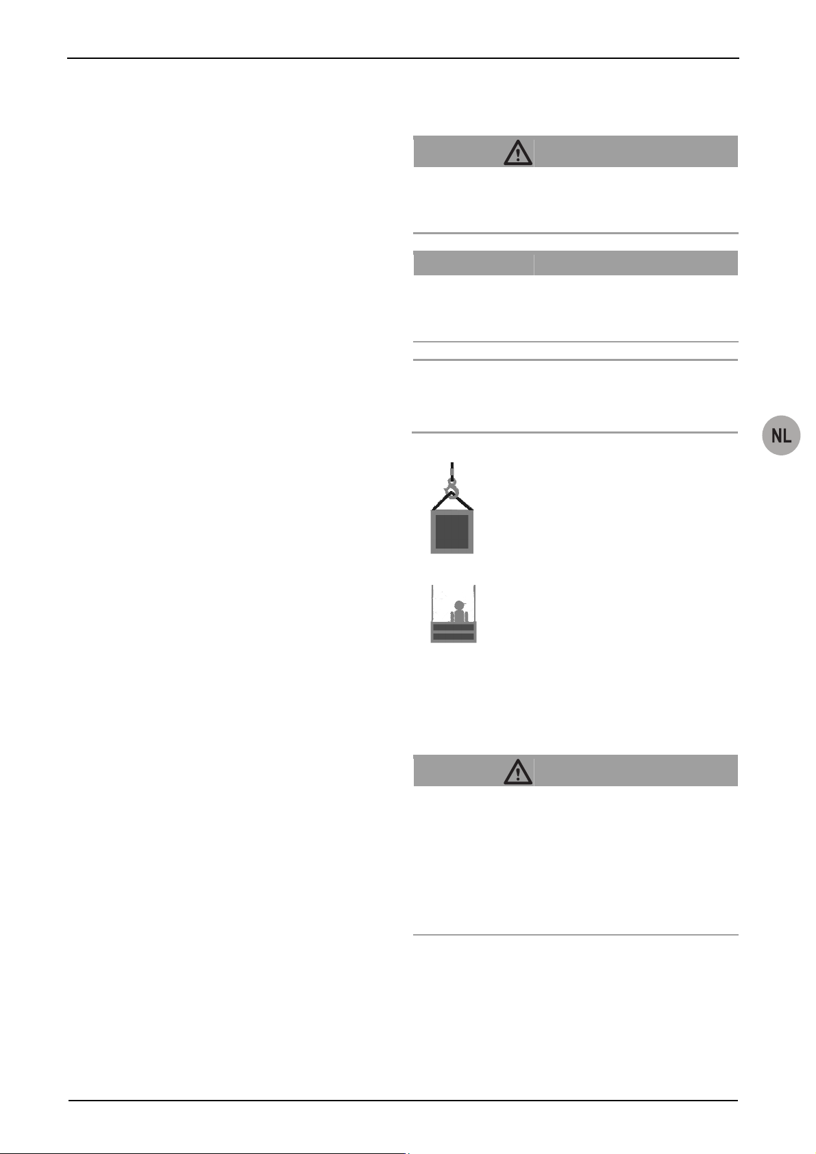
t
t
Opvangvoorziening
1.2 Toegepaste symbolen
Inrichting voor het opvangen van lastopnamemiddelen voor
materiaal bij breuk van de draagkabel of storingen bijv. falen van
de aandrijving.
Totale aangehangen last
De totale aangehangen last is de op de ophanging inwerkende
statische last, die samengesteld is uit de nuttige last, het eigen
gewicht van het lastopnamemiddel, de extra uitrusting, de
staalkabels en de stuur- en aansluitkabels.
Aard en bron van het gevaar.
Gevolg: bijv. dodelijk of ernstig lichamelijk letsel.
– Maatregelen waarmee gevaar wordt voorkomen.
Hijswerktuig / machine voor het hijsen van lasten
Apparaat of inrichting bestaand uit een apparaat met
draagmiddelen voor het hijsen of verplaatsen van lasten (bijv.
kabellier of kabellier met kabel en wartelhaak).
Klant / eindklant
De klant of eindklant is de klant van de installatiefabrikant en kan
gelijktijdig ook de exploitant zijn.
Lastopnamemiddelen (LAM)
Een niet tot het hijswerktuig behorende component of uitrusting,
die het mogelijk maakt om de last aan te slaan en tussen
machine en last of aan de last zelf aangebracht wordt of ertoe
Aard en bron van het gevaar.
Gevolg: bijv. materiële schade of milieuschade.
– Maatregelen waarmee schade wordt vermeden.
Aanwijzing:
Dit symbool kenmerkt geen veiligheidsaanwijzingen maar levert
informatie voor een beter begrip van de processen.
bestemd is om een integraal bestanddeel van de last te worden.
Als lastopnamemiddelen gelden ook aanslagmiddelen en hun
bestanddelen.
Materiaalopnamemiddel (MAM)
Lastopnamemiddel voor materiaal.
Nominale last
De nominale last is de last die op het product inwerkt. De
maximale nominale last komt overeen met het draagvermogen.
Personenhefmiddel (PAM)
Lasthefmiddel voor personen. Hiertoe behoren ook combinaties
van lasthefmiddelen voor materiaal en personen.
Deskundige persoon
Een als zodanig benoemde en adequaat opgeleide persoon die
2 Veiligheid
door zijn kennis en praktijkervaring in staat is om met behulp van
de relevante instructies en aanwijzingen de noodzakelijke
werkzaamheden veilig uit te voeren.
2.1 Algemene veiligheidsaanwijzingen
Met kabels in aanraking komende producten
Met kabels in aanraking komende producten zijn lieren,
omkeerrollen, opvanginrichtingen en andere producten waar de
kabel doorheen loopt of waarmee de kabels in contact staan.
Draagvermogen
Risico op ernstige ongevallen door foutieve werking,
verkeerd gebruik en foutieve bediening!
– Neem de volgende gegevens in acht zodat de veilige en
Het draagvermogen geeft aan met welke last het product
maximaal belast mag worden.
– Neem ook de speciale veiligheidsaanwijzingen voor alle
Draagmiddel
Een draagmiddel is een met het hijswerktuig verbonden inrichting
voor de opname van lastopnamemiddelen, aanslagmiddelen of
lasten (bijv. een met de draagkabel vast verbonden haak).
– Foutieve of beschadigde opvangvoorzieningen, kabels of
Onderhoudspersoneel
Een door de Greifzug Hebezeugbau GmbH voor het onderhoud
– De apparaten mogen mag alleen met een origineele kabel
aangewezen en geschoolde persoon met geldig certificaat, die in
staat is om met de benodigde instructies en aanwijzingen de
noodzakelijke onderhouds-, controle- en
reparatiewerkzaamheden veilig uit te voeren.
– Kabel, lier, opvangvoorziening en aanslagmiddelen mogen
Montage- en Bedieningshandleiding
GEVAAR!
OPGELET!
Met dit symbool zijn apparaten voor he
materiaaltransport gemarkeerd.
Met dit symbool zijn apparaten voor he
personen- en materiaaltransport gemarkeerd.
GEVAAR!
correcte werking en inzet van het apparaat gewaarborgd
zijn!
uit te voeren werkzaamheden in de afzonderlijke
hoofdstukken van deze handleiding in acht.
aanslagmiddelen mogen niet worden gebruikt.
met de in deze handleiding aangegeven kabeldiameters
worden gebruikt.
niet met sterk vervuilende bouwstoffen zoals bijv. beton,
G905.5 - 02/2011 NL-3
Page 72

Montage- en Bedieningshandleiding
expoyhars of andere aanhechtende arbeidsmiddelen
verontreinigd worden. Bescherm de componenten tegen
verontreinigingen! In een sterk vervuilde omgeving
hulpborstels voor de kabelreiniging gebruiken.
– De kabel niet met disulfidehoudende smeermiddelen (bijv.
Molycote
®
) smeren.
– Let op de slijtagegrens van de kabel, zie '16.3 Service en
onderhoud, Kabel' op pagina 16.
– Het reinigen van de kabel of van opvangvoorzieningen met
een hoogdrukreiniger is verboden! Binnendringend vocht
leidt tot storingen.
– Vuil aan de kabel leidt tot voortijdige slijtage of tot het
kapotgaan van kabel, aanslagmiddelen en
opvangvoorziening.
– Let op de aanwijzingen voor transport, opslag en reiniging
vanaf pagina 15.
– Let op de veiligheidsinformatiebladen voor de gebruikte
smeerstoffen van de betreffende fabrikant.
– Bevestigingsmiddelen moeten overeenstemmen met de
gegevens in deze handleiding resp. met de geldige
normen/richtlijnen.
– Het toegelaten draagvermogen mag niet worden
overschreden.
– Reparatie- en onderhoudswerkzaamheden mogen alleen
door geautoriseerd onderhoudspersoneel worden
uitgevoerd, zie '16.1 Geautoriseerd onderhoudspersoneel'
op pagina 15.
– Zelfborgende moeren mogen niet opnieuw worden gebruikt
en moeten vervangen worden.
– Montage en bediening mogen alleen door geschoold en
geïnstrueerd personeel plaatsvinden met inachtneming van
deze handleiding.
– De opvangvoorziening moet zodanig zijn bevestigd dat een
kabel van boven loodrecht de opvangvoorziening
binnenloopt. De opvangvoorziening moet zich vrij aan de
kabel kunnen uitlijnen. De kabel moet met een spangewicht
of een overeenkomstige opwikkelinrichting zijn gespannen.
– Werkzaamheden aan elektrische uitrustingen mogen alleen
door een vakkundige elektromonteur of door geïnstrueerde
personen onder toezicht van een vakkundige
elektromonteur volgens de elektrotechnische normen,
voorschriften en regels worden uitgevoerd.
– Begeef u niet onder zwevende lasten. Indien nodig de
gevarenzone afschermen. Vastgehaakte of klemzittende
lasten opvangen en beveiligen.
– Tijdens de werking van de lier niet de kabel vastpakken.
– Bij laswerkzaamheden dienen de nationale veiligheids- en
arbovoorschriften in acht genomen te worden (bijv. in
Duitsland BGR 159).
2.2 Aanwijzingen voor de exploitant
– Wanneer er meer dan één persoon betrokken is bij de hier
beschreven activiteiten, dan dient de exploitant een
toezichthouder te benoemen, die bevoegd is tot het geven
van opdrachten.
– De exploitant is er verantwoordelijk voor dat er duidelijke
bedienings-, reparatie-, onderhouds- en overige
gebruiksaanwijzingen beschikbaar zijn en dat door scholing
en instructie van het personeel een vakkundige en correcte
werking en bediening van het apparaat gewaarborgd zijn.
– Aangebrachte waarschuwingsstickers en
aanwijzingenborden moeten altijd leesbaar zijn.
Ontbrekende of niet meer leesbare waarschuwingsstickers
en aanwijzingenborden moeten per omgaande vervangen
worden.
– De gebruiker is verantwoordelijk voor de reglementaire
werking van de installatie en voor het aanhouden van de
onderhoudsintervallen en het uitvoeren van
onderhoudswerkzaamheden.
– De exploitant is verplicht het meegeleverde logboek bij te
houden.
– Binnen de Europese Unie geldt de EU-richtlijn 89/391/EEG
(in Duitsland de "Betriebssicherheitsverordnung"
(BetrSichV)). De nationale voorschriften met betrekking tot
de arbeidsveiligheid in het land van de exploitant moeten in
acht worden genomen.
– Stel geschikte veiligheidsuitrusting beschikbaar zoals bij.
veiligheidshandschoenen, gehoorbescherming en
valbescherming. Tot de persoonlijke veiligheidsuitrusting
behoort ook de bescherming tegen extreme
weersomstandigheden (bijv. zonwering, koudebescherming).
– Zorg altijd voor voldoende verlichting van de werkplek.
– Aan het ingeschakelde personeel dient men deze
handleidingen en de handleidingen van het toebehoor te
overhandigen. De documenten moeten op elk moment
toegankelijk zijn.
– Daar de Greifzug Hebezeugbau GmbH de latere
toepassing van het hier beschreven product niet kent, is de
exploitant verplicht het personeel over verdere
veiligheidsinstructies en over aanvullende
onderhoudswerkzaamheden te informeren.
– Voor de keuze van de bevestigingsmethode en geschikte
aanslagmogelijkheden is de exploitant van de installatie
verantwoordelijk.
– Bevestigingsmiddelen moeten in overeenstemming zijn met
de gegevens in deze handleiding resp. met de geldige
normen/richtlijnen.
– Wanneer geen originele onderdelen worden gebruikt, is een
veilig bedrijf niet gegarandeerd. Dit geldt vooral, wanneer
niet de voorgeschreven en voor het gebruik toegelaten
originele kabels worden gebruikt. De garantieaanspraak
tegenoverover de producent vervalt dan. Bij producten met
CE-markering verliest deze haar geldigheid.
– Let op het toegelaten temperatuurbereik, zie tabel 1 op
pagina II.
NL-4 G905.5 - 02/2011
Page 73

2.3 Verantwoordelijkheid van de
installatiefabrikant
– De installatiefabrikant is verantwoordelijk voor het ontwerp,
de vervaardiging, de montage, het in verkeer brengen en de
CE-markering van de installatie en voor het opstellen van de
EG-conformiteitverklaring.
– De bij de levering door Greifzug Hebezeugbau GmbH
inbegrepen producten moeten door de installatiefabrikant
zorgvuldig geselecteerd, reglementair toegepast en volgens
de gegevens van de montage- en bedieningshandleiding
worden gemonteerd.
– De schroefverbindingen voor de bevestiging van de
opvangvoorziening en de spanvoorziening moeten volgens
de bouwtechnische uitvoering worden geconfigureerd.
– De informatie en de aanwijzingen van deze montage- en
bedieningshandleiding moeten in de gebruiksaanwijzing en
de documentatie van de installatiefabrikant worden verwerkt
en met installatiespecifieke gegevens (bijv. handelwijze bij
storingen en blokkeringen) worden aangevuld. Het is niet
voldoende deze handleiding gewoon aan de exploitant door
te geven.
– Gegevens over het onderhoud van het product en de
accessoires moeten in het onderhoudsboek van de
installatie worden opgenomen.
3 Overzicht
3.1 Leveringstoestand
Bij levering is het product compleet gemonteerd.
3.2 Omvang van de levering
y Opvangvoorziening blocstop™ BSO
y Tractel
y Originele Montage- en Bedieningshandleiding
y Logboek
y Testcertificaten
y CE conformiteitverklaring
Omvang van de levering optioneel:
y Verbindingsmiddelen
®
-kabel conform specificatie bestelling
Montage- en Bedieningshandleiding
gebruik. Het precieze gebruiksdoel wordt door de exploitant of de
installatiefabrikant vastgelegd.
Een opvangvoorziening is een veiligheidscomponent volgens
machinerichtlijn 2006/42/EG. Veiligheidscomponenten gelden als
machine.
De opvangvoorziening mag alleen met een originele kabel met
de in deze handleiding aangegeven kabeldiameters worden
gebruikt (zie ook typeplaat).
Behalve de BSO 510 mogen alle hier beschreven apparaten als
opvangvoorziening voor personen- en materiaalhefmiddelen
worden toegepast, zie (tabel 1 op pagina II).
De opvangvoorziening BSO 510 mag alleen voor het opvangen
van materialen worden gebruikt.
Reparatie- en onderhoudswerkzaamheden mogen alleen door
geautoriseerd onderhoudspersoneel worden uitgevoerd, zie
'16.1 Geautoriseerd onderhoudspersoneel' op pagina 15.
De Greifzug Hebezeuge GmbH verklaart dat de in deze
handleiding beschreven machine aan de technische
veiligheidsvoorschriften voldoet, waaraan de producent op het
tijdstip van de marktintroductie in de Europese Unie moest
voldoen voor deze uitrusting.
De inbedrijfstelling van de machine is verboden tot de machine
waarin zij ingebouwd wordt, als geheel aan de bepalingen van de
richtlijn 2006/42/EC en aan de relevante nationale wetgeving
(waarin de richtlijn in het nationale recht geïmplementeerd wordt)
voldoet en de desbetreffende conformiteitsverklaring afgegeven
is.
y Voor machines voor het hijsen/heffen van lasten moet door
de exploitant of fabrikant van de installatie een risicoanalyse overeenkomstig bijlage I van de richtlijn
2006/42/EG worden uitgevoerd. Bij de installatieplanning
moet rekening worden gehouden met EN 14492-1.
y Voor machines voor het hijsen van personen of van
personen en goederen, die onder bijlage IV nr. 17 van de
richtlijn 2006/42/EG vallen, moet door de exploitant of
installatiefabrikant een procedure ter beoordeling van de
conformiteit met artikel 12 alinea 3 of 4 van de richtlijn
2006/42/EG worden uitgevoerd. Bij de installatieplanning
moet rekening worden gehouden met EN 14492-1 en
EN 1808.
De opvangvoorziening mag niet in installaties worden
gemonteerd die moeten overeenstemmen met de richtlijn
95/16/EG (Richtlijn personenliften, in Duitsland: 12. GPSGV).
Uitsluitingen van garantie en
aansprakelijkheid
3.3 Beschrijving van het apparaat
Zie '13 Te voorzien misbruik' op pagina 14.
Iedere van de hier genoemde gegevens afwijkende toepassing
Gebruik voor het toegelaten gebruiksdoel
geldt als oneigenlijk, niet toegelaten gebruik. Voor hieruit
resulterende schade stelt de Greifzug Hebezeugbau GmbH zich
De blocstop™ BSO met automaat voor te hoge snelheid is een
opvangvoorziening die bij elk hefwerktuig/lasthefmiddel kan
worden toegepast. Het apparaat is niet bestemd voor particulier
niet aansprakelijk. Het risico wordt alleen door de exploitant
gedragen. Tot de reglementaire toepassing behoort ook het in
acht nemen van alle aanwijzingen uit deze handleiding, in het
G905.5 - 02/2011 NL-5
Page 74

Montage- en Bedieningshandleiding
bijzonder de naleving van de montage- en
onderhoudsvoorschriften.
Toepassingsgebied
Het product is geschikt voor de volgende
bedrijfsomstandigheden:
y Voor vaste inbouwsituaties of wisselende installaties
y Voor kortdurend bedrijf
y Op hoogtes tot maximaal 1000 m boven NN
y Toegelaten temperatuurbereik: zie Tabel 1 op pagina II
GEVAAR!
Risico op ernstige ongelukken!
– 24-Uurs bedrijf is verboden.
– De toepassing in explosiegevaarlijke omgevingen is
verboden.
– De toepassing in explosiegevaarlijke omgevingen is
verboden.
1)
– De inzet in de buurt van open vuur of in een zeer hete
omgeving is verboden.
1)
Corrosiebescherming volgens bestelspecificatie
Montagevoorbeeld
De inbouwmaten van de verschillende modellen vindt u in
Tabel 2 op pagina IV.
Kabels, met kabels in aanraking komende producten en
aanslagmiddelen mogen niet met sterk verontreinigende
bouwmaterialen, zoals bijv. beton, epoxyhars of andere
hechtende materialen worden verontreinigd. Bescherm de
producten tegen verontreinigingen! In een sterk vervuilde
omgeving hulpborstels voor de kabelreiniging gebruiken.
Typeplaatjes en aanwijzingsborden/ Grenzen
aan het gebruik
Zie Afb. 4.
Pos. Aanduiding
1 Typeplaat blocstop™ BSO
2 Kabeldiameter
Op de typeplaat vindt u de noodzakelijke informatie.
Richtlijnen en normen
Maatgevende richtlijnen en normen: Zie '10.1 Richtlijnen en
normen' op pagina 8.
Zie Afb. 2.
1 Veiligheidskabel 5 tirak™-lier
2 Draagkabel 6 blocstop™ BSO
3 Activering voor
7 Spangewicht
eindschakelaar
4 Eindschakelaar "Heffen"
Bouwkundige eisen
Voor de berekening van het noodzakelijke draagvermogen moet
de maximaal mogelijke nominale last met de bedrijfscoëfficiënten
vermenigvuldigd worden.
Het draagvermogen van de lokale inrichtingen voor de
bevestiging van het product, de aanslagmiddelen en de kabels
moet minimaal overeenkomen met de nominale last
vermenigvuldigd met het bedrijfscoëfficiënt:
Opvangvoorziening: bedrijfscoëfficiënt = 5
De ophangconstructie voor kabels en producten op de locatie
moet conform richtlijn 2006/42/EG en de toepasselijke normen
(zoals bijv.: EN 1808) ontworpen zijn..
Bij personenhefmiddelen en bevestiging aan starre constructies
moet de constructie zodanig zijn geconcipieerd dat de stootfactor
onder 3 blijft (zie EN 1808, 6.5.3.6). Dit is noodzakelijk om aan
de dynamische belasting in geval van opvangincidenten te
voldoen.
Productvarianten in de handleiding
In deze handleiding worden de in Tabel 1 op pagina II vermelde
productvarianten beschreven.
4 Beschrijving
4.1 Functiebeschrijving
De opvangvoorziening beschrijft de snelheid van het
lastopnamemiddel. Bij te hoge snelheid stopt de
opvangvoorziening de neerwaartse beweging van het
lasthefmiddel door een krachtsluitende verbinding (klemmen)
aan de veiligheidskabel.
De opvangvoorziening werkt automatisch. De snelheid van de
doorlopende veiligheidskabel wordt continu door een
centrifugaalgewicht bewaakt.
Bij te hoge snelheid activeert het centrifugaalgewicht de
klemtangen. De klemtangen vangen de last op de
veiligheidskabel op. De klemtangen werken met zelfstandige
klemming. Wanneer de last tegen de hefrichting in beweegt,
trekken de klemtangen automatisch dicht. Hoe hoger hierbij de
trekkracht, des te vaster de klemwerking.
Zie Afb. 12.
Bij de inbouw van de opvangvoorziening dient men er rekening
mee te houden in welke richting de veiligheidskabel of de
opvangvoorziening bijv. bij een draagkabelbreuk versneld wordt,
NL-6 G905.5 - 02/2011
Page 75

zodat de impuls voor het stoppen van de kabel correct
geactiveerd wordt.
De remrichting (B) is de richting waarin de opdrachtvoorziening
het kabeleinde met de last tegenhoudt. De kabeldoorlooprichting
(A) is de richting waarin de kabel door de opvangvoorziening
loopt, onafhankelijk van de vraag of:
y de opvangvoorziening aan een lastendrager of een
bouwwerk bevestigd is en zich langs een gefixeerde kabel
op en neer beweegt of
y de kabel bijv. door een op de werklocatie bevestigde
opvangvoorziening loopt.
De opvangvoorziening moet zo worden gemonteerd dat de
richting (A) waarin de kabel op het moment van de storing door
de opvangvoorziening loopt, tegengesteld is aan de remrichting
(B).
Daarmee is het hijswerktuig/lastopnamemiddel tegen de
volgende schades beveiligd:
y Draagkabelbreuk
y Falen van de lier (drijfwerkbreuk)
Met de NOODSTOP-toets kan de opvangvoorziening in
noodgevallen ook handmatig geactiveerd worden.
4.2 Componenten/bouwgroepen
Zie Afb. 1.
Pos. Aanduiding Functie
1 Veiligheidskabel
2 Handhendel Vrijschakelen van de
opvangvoorziening
3 NOODSTOP-toets Handmatig activeren van de
opvangvoorziening
4 Kijkvenster Visuele controle van het
centrifugaalmechanisme tijdens de
werking
Montage- en Bedieningshandleiding
Pos. Aanduiding Functie
9 Controlestift Alleen BSO 2050/2360: Is zichtbaar bij
een correct ingevoerde
veiligheidskabel.
4.3 Technische gegevens
De technische gegevens vindt u in Tabel 1 op pagina II.
4.4 Bedrijfsmiddelen
Smeermiddelen
Toepassing Smeermiddelen
Kabel Multifunctionele olie/-vet (zonder
disulfide)
4.5 Elektrisch schema
Het elektrische schema van de lier bevindt zich in de
klemmenkast van de motor.
Zie '10.3 Montage, Opvanginrichting met eindschakelaar:
elektrische aansluiting op pagina 10.
4.6 Veiligheidsvoorzieningen
Met de NOODSTOP-toets kan de opvangvoorziening in
noodgevallen ook handmatig geactiveerd worden.
Optioneel bij opvangvoorzieningen met elektrische uitschakeling:
in opvangsituaties zorgt de eindschakelaar ervoor dat de
stuurstroom voor de neerwaartse beweging wordt onderbroken.
4.7 Bevestiging
5 Centrifugaalgewicht Bewaakt tijdens de verplaatsing
GEVAAR!
permanent de kabelsnelheid. Wanneer
de ingestelde snelheid wordt
overschreden, activeert dit het
klemtang-mechanisme.
6 Klemtangen Mechanische verbinding met de kabel
in opvang- en activeringssituaties. Hoe
hoger hierbij de trekkracht, des te
vaster de klemwerking.
7 Eindschakelaar Optioneel
8 Bevestigingsboring Opname van de bouten/schroeven
voor de bevestiging van de
opvangvoorziening op het
bevestigingsmiddel
Risico op ernstig letsel door onvakkundige bevestiging!
Verzinkte hoogvaste bouten en schroeven kunnen broos
worden en breken. Risico op een val en letsel door vallende
voorwerpen!
– Voor de bevestiging mogen geen hoogvaste verzinkte
bouten/schroeven (10.9 of 12.9) worden gebruikt.
– Gebruik bouten/schroeven met de aangegeven sterkte.
Informatie over de sterkte van bouten/schroeven vindt u in
Tabel 1 op pagina II.
Neem de informatie in acht in 'Bouwkundige eisen' op pagina 6.
De opvangvoorziening moet zodanig zijn bevestigd dat een kabel
van boven loodrecht de opvangvoorziening binnenloopt. De
opvangvoorziening moet zich vrij aan de kabel kunnen uitlijnen.
G905.5 - 02/2011 NL-7
Page 76

Montage- en Bedieningshandleiding
De kabel moet met een spangewicht of een overeenkomstige
opwikkelinrichting zijn gespannen.
Het noodzakelijke draagvermogen van ophanging en
bevestigingscomponent is afhankelijk van het model van de
opvangvoorziening.
5 Kabels
®
y Originele Tractel
-kabel
y Spaninrichting (gewichten) voor de kabel, zie afb. 6
De exploitant of de installatiefabrikant is verantwoordelijk voor de
keuze en het gebruik van accessoires die geschikt zijn voor
gebruik onder de gegeven plaatselijke omstandigheden. Verdere
voorschriften in de toepasselijke wet- en regelgevingen moeten
in acht worden genomen.
Algemeen
GEVAAR!
Verkeerde kabel of kabel met verkeerde diameter!
Door het gebruik van een verkeerde kabel bestaat een risico
op een val van hoogte, op letsel door vallende voorwerpen en
op een foute werkingswijze!
– Gebruik voor de veilige werking alleen een door de
Greifzug Hebezeugbau GmbH toegelaten originele kabel
met de correcte kabeldiameter en van de
voorgeschreven uitvoering.
De noodzakelijke kabeldiameter kunt u in de tabel Tabel 1 op
pagina II vinden.
Het type kunt u Tabel 3 op pagina 16 vinden.
Alternatieve configuraties van de kabels:
y Punt/kabelkous
y Punt/veiligheidshaak
6 Optionele toebehoren
10 Installatie en inbedrijfstelling
10.1 Richtlijnen en normen
De opvangvoorziening voldoet aan de volgende richtlijnen en
normen:
y Machinerichtlijn 2006/42/EG
y DIN EN ISO 12100
y Machines voor het hijsen van personen of van personen en
goederen (personentransport):
EN 1808:1999 + A1:2010
Voor opvanginrichtingen met eindschakelaar geldt bovendien:
y Aan de beoogde bescherming conform richtlijn 2006/95/EG
en bijl. I nr. 1.5 van de richtlijn 2006/95/EG werd voldaan.
De exploitant of de installatiefabrikant is ervoor verantwoordelijk
dat de machine binnen de in deze handleiding aangegeven
grenzen wordt gebruikt. De bovengenoemde richtlijnen en
normen alsmede EN ISO 14121 en EN ISO 13849 moeten ook in
acht worden genomen door de exploitant of producent van de
machine, waarin deze machine ingebouwd wordt.
y Bevestigingsmogelijkheden, bijv. bevestigingssets
7 Opties
De hier beschreven modellen van de opvanginrichting zijn
optioneel verkrijgbaar met eindschakelaar (bijv. blocstop™ BSO
2030 E).
Neem hiervoor direct contact op met de Greifzug Hebezeugbau
GmbH.
8 Modelvarianten
De standaard opvangsnelheid van de hier beschreven
opvangvoorzieningen bedraagt 30 m/min. Op aanvraag zijn ook
modellen met opvangsnelheden van 20, 40, 60 en 70 m/min
verkrijgbaar.
9 Noodzakelijke toebehoren
Om het product te kunnen gebruiken, heeft u de volgende
toebehoren nodig, die niet bij de levering zijn inbegrepen:
10.2 Controles voor aanvang van de
montage
Controleren van de dragende constructie
De ophangconstructie voor kabels en producten op de locatie
moet conform richtlijn 2006/42/EG en de toepasselijke normen
(zoals bijv.: EN 1808) ontworpen zijn..
Neem de informatie in acht in 'Bouwkundige eisen' op pagina 6.
Controle van de inbouwlocatie
– Controleer of een vakkundige montage van het apparaat
door andere componenten wordt belemmerd.
In de inbouwruimte mogen geen spitse of scherpgerande
componenten aanwezig zijn.
– Controleer of door de bevestiging eventueel typeplaten (zie
Afb. 4) afgedekt worden.
– De opvangvoorziening moet zodanig zijn bevestigd dat een
kabel van boven loodrecht de opvangvoorziening
binnenloopt. De opvangvoorziening moet zich vrij aan de
kabel kunnen uitlijnen. De kabel moet met een spangewicht
of een overeenkomstige opwikkelinrichting zijn gespannen.
NL-8 G905.5 - 02/2011
Page 77

– De opvangvoorziening moet zo aangebracht worden dat de
bedienende persoon op elk moment de NOODSTOP-knop
kan activeren en de werking in het zichtvenster kan
controleren. Inbouwvoorbeelden: bij een
personenopnamemiddel bijv. op het werkplatform, bij een
materiaalopnamemiddel bijv. bij de bedieningspositie.
Zie Afb. 12.
De opvangvoorziening moet zo worden gemonteerd dat de
richting (A) waarin de kabel op het moment van de storing door
de opvangvoorziening loopt, tegengesteld is aan de remrichting
(B).
Bij opvangvoorzieningen met eindschakelaar:
y aansluitmogelijkheid in de besturingskast van de lier
Montage- en Bedieningshandleiding
10.3 Montage
Voorwaarden
y De montage mag alleen door geschoold personeel
plaatsvinden.
y De werkplek moet voldoende verlicht zijn.
y De afstand tussen veiligheidskabel en draagkabel moet zo
gering mogelijk zijn.
y Positie van de bevestigingscomponent:
De afstand tussen bevestigingscomponent en
opvanginrichting moet zodanig worden gekozen dat de
kabel loodrecht in de inloopopening van de opvanginrichting
binnenloopt.
Controleren van de opvangvoorziening en de
accessoires
Opvangvoorziening
– Behuizing op schade controleren.
NOODSTOP-toets testen:
– Opvangvoorziening met de NOODSTOP-toets activeren.
Bij het sluiten moet een duidelijk klikken hoorbaar zijn.
Kabel
– Controleer of de diameter en het type van de kabel bij het
product en het toepassingsgeval passen, zie Tabel 1 op
pagina II, Tabel 3 op pagina 16 en 'Typeplaatjes en
aanwijzingsborden/ Grenzen aan het gebruik' op pagina 6.
– Controleer of de lengte van de kabel voldoende is:
De last moet veilig tot de begin- en eindpositie
verplaatsbaar zijn.
Voor de spaninrichting zijn minimaal 3 m kabeleinde nodig.
– Controleer of de kabelkous (1) en de persmanchet (2)
onbeschadigd zijn (zie Afb. 5).
– Kabels met haak:
controlleer of de haak en de borgklep (3) intact zijn, zie
Afb. 5.
– Kabel over de gehele lengte op herkenbare beschadigingen
controleren, zie Afb. 7.
– Kabelpunt volgens Afb. 9 controleren (zie ook '16.3 Service
en onderhoud, Kabel' op pagina 16).
Bevestigingsmiddelen
– Controleer of de bouten/schroeven/aanslagmiddelen aan de
specificaties in '4.7 Bevestiging' op pagina 7 voldoen.
– Controleer bevestigingspunten, lastbouten en
schroefbevestigingen op beschadigingen.
Opvangvoorziening inbouwen
GEVAAR!
Risico op ernstig letsel door onvakkundige bevestiging!
Verzinkte hoogvaste bouten en schroeven kunnen broos
worden en breken. Risico op een val en letsel door vallende
voorwerpen!
– Voor de bevestiging mogen geen hoogvaste verzinkte
bouten/schroeven (10.9 of 12.9) worden gebruikt.
– Gebruik bouten/schroeven met de aangegeven sterkte.
Risico op ernstig letsel door onvakkundige bevestiging!
Risico op een val en letsel door vallende voorwerpen!
– blocstop™ BSO 2050 en 2360 moeten in beide boringen
op de bevestigingscomponent worden bevestigd.
– De bevestigingscomponent moet met twee strips o.i.d.
zijn uitgerust.
Neem afhankelijk van de toepassingssituatie bij de inbouw de
krachtrichting van de opvangvoorziening in acht (zie ook Afb. 12
en '4.1 Functiebeschrijving' op pagina 6).
– Opvangvoorziening aan de bevestigingscomponent
bevestigen.
BSO 500 - BSO 1040: 1 bout resp. 1 schroef
Serie BSO 2050, serie BSO 2360: 2 bouten resp. 2
schroeven
– Bouten met een borgpen of vergelijkbare beveiliging borgen.
– Schroeven met zelfborgende moeren tegen verlies
beveiligen.
G905.5 - 02/2011 NL-9
Page 78

Montage- en Bedieningshandleiding
Veiligheidskabel installeren
GEVAAR!
Risico op steek- en snijwonden!
Door draadbreuken in de draadkabel kunnen draden
uitsteken! Uitstekende draden kunnen door
veiligheidshandschoenen snijden of steken!
– Geschikte zware leren handschoenen dragen bij
werkzaamheden aan de draadkabel.
– Draadkabel niet door de handen laten glijden.
Risico op ernstig letsel door onvakkundige bevestiging!
Wanneer de opvangvoorziening zich niet kan uitlijnen aan de
kabel, bestaat het risico dat deze niet correct functioneert.
– De opvangvoorziening moet zodanig zijn bevestigd dat
een kabel van boven loodrecht de opvangvoorziening
binnenloopt.
– De opvangvoorziening moet zich vrij aan de kabel
kunnen uitlijnen.
– De kabel moet met een spangewicht of een
overeenkomstige opwikkelinrichting zijn gespannen.
OPGELET!
Verkeerde montage!
Schade aan de kabel mogelijk!
– Kabel niet over randen voeren.
– Het losse kabeleinde vrij laten hangen.
Aanwijzing
Verwissel niet de veiligheidskabels en de draagkabel: Neem de
correcte kabeldiameter in acht (zie ook Afb. 4).
Zie Afb. 11.
Aansluitschema voor opvangvoorzieningen met eindschakelaar:
De schakelaar moet als openercontact aangesloten worden,
zodat een gedwongen scheiding gerealiseerd kan worden.
– Gebruik voor de aansluiting de kleuren BK (Black, zwart) en
BKWH (Black-White, zwart-wit).
Eindschakelaarkabel met insteekverbinding
– Sluit de stekker van de eindschakelaarkabel op de
besturingskast van de lier aan.
Vast bedrade verbinding
Dit werk mag alleen door een vakkundige elektricien worden
uitgevoerd.
– Eindschakelaarkabel volgens stroomloopschema in
besturingskast van de lier aansluiten.
10.4 Inbedrijfstelling
Bedrijfsklare toestand tot stand brengen
– Bevestiging van de kabel controleren.
– Verbinding tussen opvanginrichting en lastopnamemiddel
controleren.
– Controleer of de kabel loodrecht in de opvangvoorziening
binnenloopt.
– Controleer of de opvangvoorziening zich vrij aan de kabel
kan uitlijnen.
– Resultaat van de controles schriftelijk in het logboek
vastleggen.
– De kabel zodanig afrollen zodat er geen kabellussen
ontstaan.
– De kabel aan de dragende constructie bevestigen. De kabel
moet vrij hangen.
– Opvangvoorziening door omlaag drukken van de
handhendel openen.
– Kabel van bovenaf doorsteken.
BSO 2050/2360: wanneer de kabel correct werd ingevoerd,
springt de controlestift eruit.
– Kabel met de hand strak trekken.
– Twee spangewichten met elk ongeveer 11,5 kg ca. 20 cm
boven de vloer vastklemmen (zie Afb. 6).
– Losse kabeleinde vakkundig neerleggen zodat er geen
knopen of lussen worden gevormd.
Opvanginrichting met eindschakelaar:
elektrische aansluiting
in opvangsituaties zorgt de eindschakelaar ervoor dat de
stuurstroom voor de neerwaartse beweging wordt onderbroken.
Werkingstest
Zie Afb. 10 (voorbeeld).
Algemene werkingscontrole:
– Behuizing op schade controleren.
– NOODSTOP-toets (1) tijdens de afdaling indrukken.
De opvanginrichting moet sluiten en de kabel vasthouden.
Optioneel bij opvanginrichtingen met eindschakelaar:
het hefwerktuig mag niet in neerwaartse richting lopen.
– Opvanginrichting openen: handhendel (2) rechtsom
zwenken tot deze zich vergrendelt.
Werking van het centrifugaalgewicht controleren:
– tijdens elke beweging minstens een maal in het kijkvenster
(4) controleren of het centrifugaalgewicht draait.
Activering van de opvangvoorziening controleren:
De werking van de snelheidsbegrenzing kan met twee
verschillende tests gecontroleerd worden. De controlemethode is
afhankelijk van de inbouwsituatie van de opvangvoorziening.
NL-10 G905.5 - 02/2011
Page 79

y Methode 1: De opvangvoorziening wordt gedemonteerd, ca.
30 cm omhoog geheven, en aan de (verticale) kabel
losgelaten. In de valweg mogen geen delen van de
omliggende (gebouw-)constructie aanwezig zijn waar de
opvangvoorziening tegenaan zou kunnen botsen.
y Methode 2: De veiligheidskabel wordt met de hand met een
ruk door de opvangvoorziening getrokken.
Methode 1 (controle van de snelheidsbegrenzing):
GEVAAR!
Risico op letsel door vallende voorwerpen! Gevaar door
beknelling en snijpunten!
Bij de volgende controle bestaat gevaar door een risico op
beknellingen en snijwonden tussen de omlaag vallende
opvangvoorziening en delen van de omliggende (gebouwconstructie.
– Grijp niet in het valtraject van de opvangvoorziening.
Risico op letsel door vallende voorwerpen! Gevaar door
beknelling en snijpunten!
Wanneer de opvangvoorziening niet geactiveerd wordt en in
het valtraject geen obstakels aanwezig zijn, kan de
opvangvoorziening ongecontroleerd omlaag vallen en andere
mensen in gevaar brengen!
– Begrens het valtraject zo nodig door geschikte
maatregelen te nemen!
OPGELET!
Risico op schade aan de opvangvoorziening of aan
andere componenten!
Bij de volgende controle kan de opvangvoorziening in botsing
komen met delen van de omliggende (gebouw-)constructie en
daardoor beschadigd raken.
– Let erop dat de opvangvoorziening niet met obstakels op
de locatie in botsing kan komen.
– Kan een botsing niet uitgesloten worden, dan moet u een
andere controlemethode gebruiken.
– Verwijder de bevestiging van de opvangvoorziening (bijv.
bouten (3) in het getoonde inbouwvoorbeeld).
– Til de opvangvoorziening ca. 30 cm omhoog aan de kabel.
– Laat de opvangvoorziening vallen:
De opvangvoorziening moet na max. 8 cm sluiten en aan de
kabel vasthangen.
– Opvanginrichting openen: handhendel (2) rechtsom
zwenken tot deze zich vergrendelt.
– Opvangvoorziening aan de kabel neerlaten.
– Opvangvoorziening monteren:
Borg de bout met een nieuwe splitpen.
Borg de bouten met een nieuwe zelfborgende moer.
Montage- en Bedieningshandleiding
Methode 2 (controle van de snelheidsbegrenzing):
Zie Afb. 12.
– Verwijder het spangewicht aan de veiligheidskabel of maak
een kabellus bij de kabeluitloop (lastloze zijde van de
opvangvoorziening).
– Trek de kabel met een ruk in de richting 'A':
De opvanginrichting moet sluiten en de kabel vasthouden.
– Opvanginrichting openen: handhendel (2) rechtsom
zwenken tot deze zich vergrendelt.
– Span zo nodig de veiligheidskabel weer door deze met de
hand aan te trekken.
– Breng eventueel het spangewicht weer aan de
veiligheidskabel aan.
11 Bediening/bedrijf
De operator moet door de exploitant in de bediening van het
apparaat geïnstrueerd en met het gebruik ervan belast zijn.
11.1 Controles voor aanvang van het
werk
– Kabel op aangehechte vervuilingen controleren en evt.
reinigen.
– Bedrijfsklare toestand controleren, zie '10.4 Inbedrijfstelling,
Bedrijfsklare toestand tot stand brengen' op pagina 10.
– Werkingstest uitvoeren, zie '10.4 Inbedrijfstelling,
Werkingstest' op pagina 10.
– Resultaat van de controles schriftelijk in het logboek
vastleggen.
11.2 Bedrijf met een
personenopnamemiddel
GEVAAR!
Risico op letsel door te grote valafstand in geval van
opvangen!
Bij de opwaartse beweging met gesloten opvangvoorziening
wordt de veiligheidskabel omhoog gedrukt en is deze tussen
ophanging en opvangvoorziening meer gespannen.
– Controleer voor elke rit of de handhefboom op OPEN
staat en vergrendeld is.
Zie Afb. 10 (voorbeeld).
– Opvanginrichting openen: handhendel (2) rechtsom
zwenken tot deze zich vergrendelt.
– Hefwerktuig starten.
– Tijdens elke beweging minstens een maal in het kijkvenster
(4) controleren of het centrifugaalgewicht draait.
G905.5 - 02/2011 NL-11
Page 80

Montage- en Bedieningshandleiding
Aanwijzing:
Verricht deze controle liefst aan het begin van de
verplaatsing, voordat het lastopnamemiddel een grote hoogte
bereikt heeft.
Wanneer het centrifugaalgewicht niet draait:
– Zet het lastopnamemiddel meteen stil.
– Plan voor noodgevallen van de exploitant in acht nemen.
– Opvanginrichting uitbouwen en ter controle naar de Greifzug
Hebezeugbau GmbH of een geautoriseerde
hijswerktuigenwerkplaats opsturen.
Veiligheidskabel is niet gespannen
Wanneer de gesloten opvangvoorziening de veiligheidskabel
gespannen heeft:
– Hefwerktuig stoppen.
– Controleren of de kabel vrij hangt.
– Opvanginrichting openen: handhendel (2) rechtsom
zwenken tot deze zich vergrendelt.
– Span zo nodig de veiligheidskabel weer door deze met de
hand aan te trekken.
– Zet de beweging pas voort, wanneer de veiligheidskabel
weer gespannen is.
11.3 Bedrijf met een
materiaalopnamemiddel
Zie Afb. 10 (voorbeeld).
– Opvanginrichting openen: handhendel (2) rechtsom
zwenken tot deze zich vergrendelt.
– Hefwerktuig starten.
– tijdens elke beweging minstens een maal in het kijkvenster
(4) controleren of het centrifugaalgewicht draait.
Wanneer het centrifugaalgewicht niet draait:
– Zet het lastopnamemiddel meteen stil.
– Opvanginrichting uitbouwen en ter controle naar de Greifzug
Hebezeugbau GmbH of een geautoriseerde
hijswerktuigenwerkplaats opsturen.
Veiligheidskabel is niet gespannen
– Zet de beweging pas voort, wanneer de veiligheidskabel
weer gespannen is.
11.4 Handmatige NOODSTOP
Met de NOODSTOP-toets kan de opvangvoorziening in
noodgevallen ook handmatig geactiveerd worden.
11.5 Beveiligen van de last
Bij arbeidsonderbrekingen kan de opvangvoorziening worden
gebruikt voor het borgen van de last. Daardoor wordt bijv. de
overbrenging van de kabellier ontlast.
Aanwijzing:
– Neem de werkinstructies en veiligheidsmaatregelen van de
exploitant en de aanwijzingen uit de gebruiksaanwijzingen
van het hijswerktuig resp. het lastopnamemiddel in acht.
Zie Afb. 10 (voorbeeld).
Last beveiligen:
– Opvangvoorziening met de NOODSTOP-toets activeren.
Open de opvangvoorziening weer:
– Hef het platform een stukje omhoog om de kabel te
ontlasten.
– Opvanginrichting openen: handhendel (2) rechtsom
zwenken tot deze zich vergrendelt.
– Span zo nodig de veiligheidskabel weer door deze met de
hand aan te trekken.
– Zet de beweging pas voort, wanneer de veiligheidskabel
weer gespannen is.
12 Directe maatregelen in
opvangsituaties
Een opvangsituatie houdt in dat de opvangvoorziening bijv. bij
een overbrengingsbreuk in de lier of bij een breuk van de
draagkabel geactiveerd wordt.
12.1 Opvangsituatie bij
materiaalopnamemiddelen
Wanneer de gesloten opvangvoorziening de veiligheidskabel
gespannen heeft:
GEVAAR!
– Hefwerktuig stoppen.
– Controleren of de kabel vrij hangt.
– Opvanginrichting openen: handhendel (2) rechtsom
zwenken tot deze zich vergrendelt.
– Span zo nodig de veiligheidskabel weer door deze met de
hand aan te trekken.
Risico op zware ongelukken door verkeerd gedrag!
– Kalmte bewaren.
– Oorzaak controleren.
– Fout verhelpen.
Wanneer een draagkabelbreuk of een falen van het hijswerktuig
de oorzaak is:
NL-12 G905.5 - 02/2011
Page 81

– Evacuatie van de bemanning inleiden. Zie de documentatie
van het personenopnamemiddel of, indien aanwezig, het
noodreddingsplan van de eigenaar/exploitant.
– Beveilig het personenopnameiddel door geschikte
maatregelen, zodat de draagkabel of het hijswerktuig kan
worden vervangen.
– Zet vanaf de grond spanning op de veiligheidskabel.
Wanneer een draagkabelbreuk of een falen van het hijswerktuig
kan worden uitgesloten:
– Probeer omhoog te bewegen.
Wanneer dat niet mogelijk is:
– Bemanning evacueren en personenopnamemiddel
beveiligen (zie boven).
Zie Afb. 10 (voorbeeld).
Wanneer een opwaartse beweging mogelijk is, is waarschijnlijk
een storing in de opvangvoorziening opgetreden.
– Hef het platform een stukje omhoog om de kabel te
ontlasten.
– Opvanginrichting openen: handhendel (2) rechtsom
zwenken tot deze zich vergrendelt.
– Span zo nodig de veiligheidskabel weer door deze met de
hand aan te trekken.
– Neerdalen.
– NOODSTOP-toets (1) tijdens de afdaling indrukken.
Opvangvoorziening zonder eindschakelaar:
– Afdalen tot de last met de opvangvoorziening aan de
veiligheidskabel vastgehouden wordt.
Opvangvoorziening met eindschakelaar:
– Noodafdaling uitvoeren (zie documentatie van de lier of van
het personenopnamemiddel) tot de last met de
opvangvoorziening door de veiligheidskabel gedragen wordt.
Wanneer de last niet gehouden wordt:
– Bemanning evacueren en personenopnamemiddel
beveiligen (zie boven).
Wanneer de last gehouden wordt:
– Hef het platform een stukje omhoog om de kabel te
ontlasten.
– Opvanginrichting openen: handhendel (2) rechtsom
zwenken tot deze zich vergrendelt.
– Het lastopnamemiddel voorzichtig neerlaten en daarbij
steeds paraat zijn om de NOODSTOP-toets op de
opvangvoorziening in te drukken.
Na elk opvangen:
Zie '12.3 Maatregelen na een storing of na opvangen' op
pagina 14.
Montage- en Bedieningshandleiding
12.2 Opvangsituatie bij
materiaalopnamemiddelen
GEVAAR!
Risico op letsel door vallende lasten!
– Blijf niet onder de materiaalopnamemiddelen staan.
– Oorzaak van de storing controleren.
– Fout verhelpen.
Wanneer een draagkabelbreuk of een falen van het hijswerktuig
de oorzaak is:
– Beveilig het lastopnameiddel door geschikte maatregelen,
zodat de draagkabel of het hijswerktuig kan worden
vervangen.
Wanneer een draagkabelbreuk of een falen van het hijswerktuig
kan worden uitgesloten:
– Probeer omhoog te bewegen.
Wanneer dat niet mogelijk is:
– Lastopnamemiddelen beveiligen (zie boven).
Zie Afb. 10 (voorbeeld).
Wanneer een opwaartse beweging mogelijk is, is waarschijnlijk
een storing in de opvangvoorziening opgetreden.
– Hef het platform een stukje omhoog om de kabel te
ontlasten.
– Opvanginrichting openen: handhendel (2) rechtsom
zwenken tot deze zich vergrendelt.
– Span zo nodig de veiligheidskabel weer door deze met de
hand aan te trekken.
– Neerdalen.
– NOODSTOP-toets (1) tijdens de afdaling indrukken.
Wanneer de last niet gehouden wordt:
– Beveilig het lastopnamemiddel door geschikte maatregelen
te nemen.
Wanneer de last gehouden wordt:
– Hef het platform een stukje omhoog om de kabel te
ontlasten.
– Opvanginrichting openen: handhendel (2) rechtsom
zwenken tot deze zich vergrendelt.
– Het lastopnamemiddel voorzichtig neerlaten en daarbij
steeds paraat zijn om de NOODSTOP-toets op de
opvangvoorziening in te drukken.
Na elk opvangen:
Zie '12.3 Maatregelen na een storing of na opvangen' op
pagina 14.
G905.5 - 02/2011 NL-13
Page 82
Montage- en Bedieningshandleiding
12.3 Maatregelen na een storing of na
opvangen
GEVAAR!
Risico op ernstige ongelukken!
Bij een opvangactie wordt de gehele constructie belast door
plotseling optredende krachten. Schade is mogelijk aan de
ophangconstructie, de bevestigingsmiddelen, de kabel en de
opvangvoorziening.
– De opvangvoorziening moet door de Greifzug
Hebezeugbau GmbH of een geautoriseerde
hijswerktuigenwerkplaats gecontroleerd worden.
– Een deskundige persoon moet een controle op de
inzetlocatie verrichten.
– Opvanginrichting uitbouwen en ter controle naar de Greifzug
Hebezeugbau GmbH of een geautoriseerde
hijswerktuigenwerkplaats opsturen.
Controle door een deskundige persoon op de inzetlocatie:
y Veiligheidskabel
y Ophanging van de veiligheidskabel
y Bevestigingspunt van de opvangvoorziening op de locatie
resp. bevestigingspunt aan het lastopnamemiddel
y Alle bouten en schroefverbindingen
In geval van een activering is een controle niet noodzakelijk.
13 Te voorzien misbruik
Aanspraken op garantie of schadevergoeding bij persoonlijke en
materiële schades zijn uitgesloten wanneer deze tot een of
meerdere van de volgende oorzaken kunnen worden herleid:
y Oneigenlijk, niet toegelaten gebruik van het product, de
toebehoren of tot het product behorende draagmiddelen.
y BSO 510: Vervoer van personen.
y Bedrijf met een vervuilde kabel.
y Inzet in explosiegevaarlijke omgevingen of corrosieve
omgeving.
y Niet nageleefde onderhoudsintervallen.
y Reiniging met een hogedrukreiniger.
y Onvakkundige montage, inbedrijfstelling, bediening,
onderhoud en reparatie.
y Bedrijf met een elektrische aansluiting die niet voldoet aan
de aanwijzingen en specificaties in deze handleiding.
y Gebrekkige bewaking van de delen van het apparaat en de
toebehoren die aan slijtage onderhevig zijn.
y Onvakkundig en onbevoegd uitgevoerde reparaties.
y Gebruik van niet-originele reserveonderdelen.
y Veranderingen aan instellingen van veiligheidsinrichtingen.
y Achterwege gelaten metingen en controles voor de
preventie van schade.
y Overbelasten van het product
y Vasklemmen/vastlopen van de handhefboom
y Rampen door inwerking van vreemde voorwerpen en
overmacht.
y Voor schades die het gevolg zijn van ombouw en
modificatie van producten en van het gebruik van niet
originele onderdelen waarvoor de producent geen
schriftelijke toestemming verleend heeft, stelt de producent
zich niet aansprakelijk.
y Foutieve of beschadigde producten, accessoires en
aanslagmiddelen mogen niet worden gebruikt.
y Aanslaan van de veiligheidskabel op het zelfde aanslagpunt
als de draagkabel
y Hijsen met slappe veiligheidskabel
y Toepassing bij een personenopnamemiddel met een
hijswerktuig waarvan de kabelsnelheid hoger is dan
18 m/min.
Bij transport van personen:
y Gebruik van de opvangvoorziening op de draagkabel
14 Demontage
GEVAAR!
Risico op steek- en snijwonden!
Door draadbreuken in de draadkabel kunnen draden
uitsteken! Uitstekende draden kunnen door
veiligheidshandschoenen snijden of steken!
– Geschikte zware leren handschoenen dragen bij
werkzaamheden aan de draadkabel.
– Draadkabel niet door de handen laten glijden.
– Spangewichten van veiligheidskabel verwijderen.
OPGELET!!!
Verhoogde slijtage of beschadiging door niet correct
geopende opvangvoorziening!
– Hendel van de opvangvoorziening steeds tot aan de
aanslag doordrukken en vastjouden tot de kabel eruit
getrokken is.
– Opvanginrichting openen: handhendel (2) rechtsom
zwenken tot deze zich vergrendelt.
Handhendel tot de aanslag doordrukken en vasthouden.
– Veiligheidskabel met de hand naar boven eruit trekken.
– Opvangvoorziening demonteren: verwijder de schroeven en
bouten.
– Wikkel tijdens het neerlaten de kabels correct (1) op de
haspels, zodat er geen lussen of knopen (2) in de kabel
ontstaan die de kabel onbruikbaar maken., zie Afb. 8.
NL-14 G905.5 - 02/2011
Page 83
Montage- en Bedieningshandleiding
15 Transport en opslag
15.1 Transport
Algemene transportaanwijzingen
Vermijd beschadigingen tijdens het vervoer.
Bij zware componenten geschikte transporthulpmiddelen
gebruiken of de verplaatsing met een tweede persoon uitvoeren.
Kabel
– De kabels tegen direct zonlicht, chemicaliën,
verontreinigingen en mechanische beschadigingen
beschermen.
– Kabels indien mogelijk op de haspel transporteren.
– Opgerolde kabels zonder haspel met een strop optillen en
transporteren.
– Belasting door het eigengewicht zo gering mogelijk houden.
15.2 Opslag
Algemene opslagvoorwaarden:
y droog (maximaal 75% relatieve luchtvochtigheid)
y stofvrij
y gelijkmatige omgevingstemperatuur
Opslagvoorwaarden voor kabels:
y Licht ingevet
y Contact met chemicaliën vermijden (bijv. accuzuur).
y Zonder mechanische knel-, druk- of trekbelasting
16.2 Noodzakelijke controles
Voor de jaarlijkse veiligheidsinspectie en buitengewone controles
is een schriftelijk testcertificaat noodzakelijk. De
inspecties/controles moeten in het meegeleverde logboek
worden geregistreerd.
Voor ieder gebruik
De correcte toestand moet voor elk gebruik gecontroleerd
worden, zie '10.4 Inbedrijfstelling' op pagina 10.
Jaarlijkse veiligheidscontrole
De veiligheidscontrole moet jaarlijks worden uitgevoerd.
De veiligheidscontrole mag alleen door geautoriseerd
onderhoudspersoneel worden uitgevoerd, zie
'16.1 Geautoriseerd onderhoudspersoneel' op pagina 15.
Afhankelijk van de bedrijfsomstandigheden (bijv. inzet in een
sterk vervuilde omgeving) kan een tussentijdse controle
noodzakelijk zijn.
Wij adviseren een fabriekscontrole door de Greifzug
Hebezeugbau GmbH.
Neem direct contact op met de Greifzug Hebezeugbau GmbH of
uw leverancier.
Buitengewone inspectie
Na een opvangsituatie of een storing moet de opvangvoorziening
door de Greifzuf Hebezeugbau GmbH of een geautoriseerde
hijswerktuigenwerkplaats worden gecontroleerd.
Zie '12.3 Maatregelen na een storing of na opvangen' op
pagina 14.
16 Onderhoud
16.3 Service en onderhoud
16.1 Geautoriseerd onderhoudspersoneel
GEVAAR!
Risico op een val! Risico op letsel door vallende
voorwerpen!
Levensgevaar door foutief uitgevoerde reparatie- en
onderhoudswerkzaamheden!
Reparatie- en onderhoudswerkzaamheden die het openen
van het product noodzakelijk maken, mogen alleen door de
volgende geautoriseerde instanties worden uitgevoerd:
– de Greifzug Hebezeugbau GmbH
– werkplaatsen voor heftoestellen die door de Greifzug
Hebezeugbau GmbH geautoriseerd zijn.
– Onderhoudspersoneel dat door de Greifzug
Hebezeugbau GmbHopgeleid en gecertificeerd is.
G905.5 - 02/2011 NL-15
Interval Werk Uitvoering
wekelijks
– Veiligheidskabel smeren
Operator
– Behuizing van de
opvangvoorziening reinigen
1 x per jaar
of eens per
250
bedrijfsuren
van de lier
Indien
nodig
– Slijtage van de klemtangen
controleren
– Slijtage van de aandruk-
/aandrijfrollen controleren
– Klemtangen vervangen
– Aandruk-/aandrijfrollen
Geautoriseerd
onderhoudspersoneel
Geautoriseerd
onderhoudspersoneel
vervangen
Page 84

Montage- en Bedieningshandleiding
Interval Werk Uitvoering
Indien
nodig
– Veiligheidskabel vervangen
Door exploitant
aangewezen en
geïnstrueerde
persoon
Kabel
GEVAAR!
Risico op steek- en snijwonden!
Door draadbreuken in de draadkabel kunnen draden
uitsteken! Uitstekende draden kunnen door
veiligheidshandschoenen snijden of steken!
– Geschikte zware leren handschoenen dragen bij
werkzaamheden aan de draadkabel.
– Draadkabel niet door de handen laten glijden.
Reinigen
Verontreinigde plekken indien nodig droog afborstelen. Evt.
opnieuw smeren.
Smeren
GEVAAR!
Neerstortgevaar door gladde veiligheidskabel!
Ernstig of dodelijk letsel mogelijk!
– De veiligheidskabel niet met disulfidehoudende
smeerstoffen (bijv. Molycote
– Gebruik multifunctioneel vet of olie.
– Het reinigen van de kabel of van de opvangvoorziening
met een hoogdrukreiniger is verboden! Binnendringend
vocht leidt tot storingen, defecten en schades.
– Vuil aan de kabel leidt tot voortijdige slijtage of tot het
kapotgaan van kabel, aanslagmiddelen en
opvangvoorziening.
Vervangen
Vervang de kabel meteen, wanneer de slijtagegrens volgens
Tabel 3 bereikt is (volgens ISO 4309 en DIN 15020, blad 2) of
typische kabelgebreken aanwezig zijn, zie Afb. 7.
®
) smeren.
Constructie van de kabel
4 x 26
4 x 36 5 x 19 5 x 26 5 x 31
Verdraaiingsarm
kabeldiameter
Minimale toegelaten
[mm]
kabel
Nominale diameter van de
[mm] Aantal zichtbare draadbreuken in de buitenaders op
een lengte van 30 x de nominale diameter van de
kabel.
6
8 5,9
8 10 10 8 11 7,5
9 10 10 8
10 8
8,5
11 9,3
11,5 10 11 10,5
14 10 11 13,1
16 13 13 15,0
Tabel 3
Uitvoering: Zie '14 Demontage' op pagina '14 en '10.3 Montage'
op pagina 9.
Kabelpunt vervangen
De kabel naar de Greifzug Hebezeugbau GmbH of een door de
Greifzug Hebezeugbau GmbH geautoriseerde
hefwerktuigwerkplaats sturen en de kabelpunt laten vervangen.
16.4 Reserveonderdelen bestellen
Reserveonderdelenlijsten zijn verkrijgbaar bij uw leverancier of
direct van de Greifzug Hebezeugbau GmbH.
Noodzakelijke gegevens voor de bestelling vindt u op de
typeplaatjes van de afzonderlijke componenten, zie 'Typeplaatjes
en aanwijzingsborden/ Grenzen aan het gebruik' op pagina 6.
Noodzakelijk gegevens zijn bijv.:
Opvangvoorziening: Artikelnummer, type
NL-16 G905.5 - 02/2011
Page 85
17 Afvalverwijdering en
milieubescherming
Het apparaat werd uit recyclebaar materiaal vervaardigd.
Wanneer het apparaat later wordt verschroot, moet het apparaat
volgens de toepasselijke voorschriften als afval worden
verwijderd. Binnen de Europese Unie geldt de nationale
implementatie van de richtlijn voor afvalstoffen 75/442/EEG (in
Duitsland 'Kreislaufwirtschafts- und Abfallgesetz' (KrWAbfG)).
Volgens richtlijn 2002/96/EG, in Duitsland geïmplementeerd via
het 'Elektro- und Elektronikgerätegesetz' (ElektroG), is de
fabrikant verplicht bepaalde elektrische en elektronische
componenten terug te nemen en af te voeren. De componenten
die hierdoor betroffen zijn, worden op het typeplaatje met het
volgende symbool gekenmerkt:
Montage- en Bedieningshandleiding
G905.5 - 02/2011 NL-17
Page 86

Montage- en Bedieningshandleiding
18 Opsporen van fouten/Verhelpen van storingen
Storing
Oorzaak Oplossing
Opvanginrichting kan niet worden geopend
Opvanginrichting houdt de last aan de veiligheidskabel vast.
Mechanisch defect.
– Last door omhoog bewegen op de draagkabel verplaatsen.
– Opvanginrichting vervangen en laten repareren.
Opvanginrichting activeert bij normale beweging.
Opvangsituatie
Snelheid van het hefwerktuig te hoog.
Activeringssnelheid van de opvanginrichting is fout ingesteld.
Snelheidsverschil tussen draagkabel en veiligheidskabel te hoog bij het
starten.
– Zie '12 Directe maatregelen in opvangsituaties' op pagina 12.
– Hefwerktuig controleren.
– Opvanginrichting vervangen en laten repareren.
– Spangewicht op veiligheidskabel ontbreekt. Spangewicht
aanbrengen.
Centrifugaalgewicht draait niet.
Verontreiniging of defect.
IJsvorming
– Opvanginrichting vervangen en laten reinigen resp. repareren.
– Met hete lucht voorzichtig tot max. 70 °C verwarmen.
BSO 2050/2360: De controlestift is na het invoeren van de veiligheidskabel niet zichtbaar.
Kabel niet correct ingevoerd.
Mechanisch defect.
– Kabel eruit trekken en opnieuw doorsteken.
– Opvanginrichting vervangen en laten repareren.
Opvanginrichting met eindschakelaar: Het werkplatform kan stijgen, maar niet afdalen.
Eindschakelaarverbinding naar hefwerktuigbesturing onderbroken.
Kabelbreuk
Eindschakelaar defect.
– Insteekverbinding tot stand brengen.
– Kabel door elektromonteur laten vervangen.
– Door elektricien laten controleren en opvanginrichting evt. laten
repareren.
Kabel kan niet worden ingevoerd.
Kabelpunt defect.
– Kabelpunt vervangen, zie '16.3 Service en onderhoud, Kabel' op
pagina 16.
Opvanginrichting is gesloten.
– Opvanginrichting openen (spannen).
NL-18 G905.5 - 02/2011
Page 87

19 EG-Conformiteitverklaring (uittreksel)
19.1 Opvangvoorziening voor personentransport
Montage- en Bedieningshandleiding
Bij deze verklaar de producent,
Greifzug Hebezeugbau GmbH
Scheidtbachstraße 19–21 51469 Bergisch Gladbach
vertegenwoordigd door
Dr. Ing. Uwe Schuht
Directeur
CONFORMITEITSVERKLARING
dat de aangeduide uitrusting aan de technische veiligheidsvoorschriften voldoet, die voor deze uitrusting van toepassing waren op het
tijdstip van marktintroductie in de EUROPESE UNIE door de producent.
TOEGEPASTE NORMEN EN RICHTLIJNEN:
2006/42/EC;
EN 1808; EN ISO 12100-1; EN ISO 12100-2; EN ISO 14121-1
AANDUIDING
Opvangvoorziening
TOEPASSING
Personentransport
TYPE
BSO 500, BSO 520, BSO 1000, BSO 1020, BSO 1030, BSO 1040
SERIENUMMER
Bouwjaar:
vanaf 01.2010
De bovengenoemde machine komt overeen met het model van de typetest die onder één van de volgende certificaatnummer
afgenomen werd.
08 040
De inbedrijfstelling van de machine is verboden tot de machine waarin zij ingebouwd wordt, als geheel aan de bepalingen
van de richtlijn 2006/42/EG en aan de relevante nationale wetgeving (waarin de richtlijn in het nationale recht
geïmplementeerd wordt) voldoet en de desbetreffende conformiteitsverklaring afgegeven is.
De actuele versie van EN 1808 moet worden gebruikt voor het personenopnamemiddel, waarin deze machine ingebouwd is.
Afgifte van het typetestcertificaat vond plaats door:
Fachausschuss MHHW
Test- en certificeringsinstituut in de BG-PRÜFZERT
Graf-Recke-Straße 69
40239 Düsseldorf
aangemeld onder nr. 0393 bij de Europese Commissie
Verantwoordelijke voor de documentatie:
Dr.Ing. Uwe Schuht, tel.: +49 (0) 2202 1004 63
Bergisch Gladbach, datum
G905.5 - 02/2011 NL-19
Page 88
Montage- en Bedieningshandleiding
Bij deze verklaar de producent,
Greifzug Hebezeugbau GmbH
Scheidtbachstraße 19–21 51469 Bergisch Gladbach
vertegenwoordigd door
Dr. Ing. Uwe Schuht
Directeur
CONFORMITEITSVERKLARING
dat de aangeduide uitrusting aan de technische veiligheidsvoorschriften voldoet, die voor deze uitrusting van toepassing waren op het
tijdstip van marktintroductie in de EUROPESE UNIE door de producent.
TOEGEPASTE NORMEN EN RICHTLIJNEN:
2006/42/EC;
EN 1808; EN ISO 12100-1; EN ISO 12100-2; EN ISO 14121-1
AANDUIDING
Opvangvoorziening
TOEPASSING
Personentransport
TYPE
BSO 2050, BSO 2360
SERIENUMMER
Bouwjaar:
vanaf 01.2010
De bovengenoemde machine komt overeen met het model van de typetest die onder één van de volgende certificaatnummer
afgenomen werd.
09 261
De inbedrijfstelling van de machine is verboden tot de machine waarin zij ingebouwd wordt, als geheel aan de bepalingen
van de richtlijn 2006/42/EG en aan de relevante nationale wetgeving (waarin de richtlijn in het nationale recht
geïmplementeerd wordt) voldoet en de desbetreffende conformiteitsverklaring afgegeven is.
De actuele versie van EN 1808 moet worden gebruikt voor het personenopnamemiddel, waarin deze machine ingebouwd is.
Afgifte van het typetestcertificaat vond plaats door:
Vakcommissie Bau (BAU) en Tiefbau (TB)
Test- en certificeringsinstituut in de BG-PRÜFZERT
Landsberger Str. 309
80687 München
, aangemeld onder nr. 0393 bij de Europese Commissie
Verantwoordelijke voor de documentatie:
Dr.Ing. Uwe Schuht, tel.: +49 (0) 2202 1004 63
Bergisch Gladbach, datum
NL-20 G905.5 - 02/2011
Page 89

19.2 Opvangvoorziening voor materiaaltransport
Montage- en Bedieningshandleiding
Bij deze verklaar de producent,
Greifzug Hebezeugbau GmbH
Scheidtbachstraße 19–21 51469 Bergisch Gladbach
vertegenwoordigd door
Dr. Ing. Uwe Schuht
Directeur
CONFORMITEITSVERKLARING
dat de aangeduide uitrusting aan de technische veiligheidsvoorschriften voldoet, die voor deze uitrusting van toepassing waren op het
tijdstip van marktintroductie in de EUROPESE UNIE door de producent.
TOEGEPASTE NORMEN EN RICHTLIJNEN:
2006/42/EC;
EN ISO 12100-1; EN ISO 12100-2; EN ISO 14121-1
AANDUIDING
Opvangvoorziening
TOEPASSING
Materiaaltransport
TYPE
BSO 510
SERIENUMMER
Bouwjaar:
vanaf 01.2010
De inbedrijfstelling van de machine is verboden tot de machine waarin zij ingebouwd wordt, als geheel aan de bepalingen
van de richtlijn 2006/42/EG en aan de relevante nationale wetgeving (waarin de richtlijn in het nationale recht
geïmplementeerd wordt) voldoet en de desbetreffende conformiteitsverklaring afgegeven is.
Verantwoordelijke voor de documentatie:
Dr.Ing. Uwe Schuht, tel.: +49 (0) 2202 1004 63
Bergisch Gladbach, datum
G905.5 - 02/2011 NL-21
Page 90

Montage- en Bedieningshandleiding
NL-22 G905.5 - 02/2011
Page 91

Page 92

G905.5 - 02/2011 / 102890 / EN-DE-FR-NL / © Greifzug Hebezeugbau GmbH
 Loading...