

Gregson-Clark
3213 Lehigh Street
Caledonia, NY 14423
www.GregsonClark.com
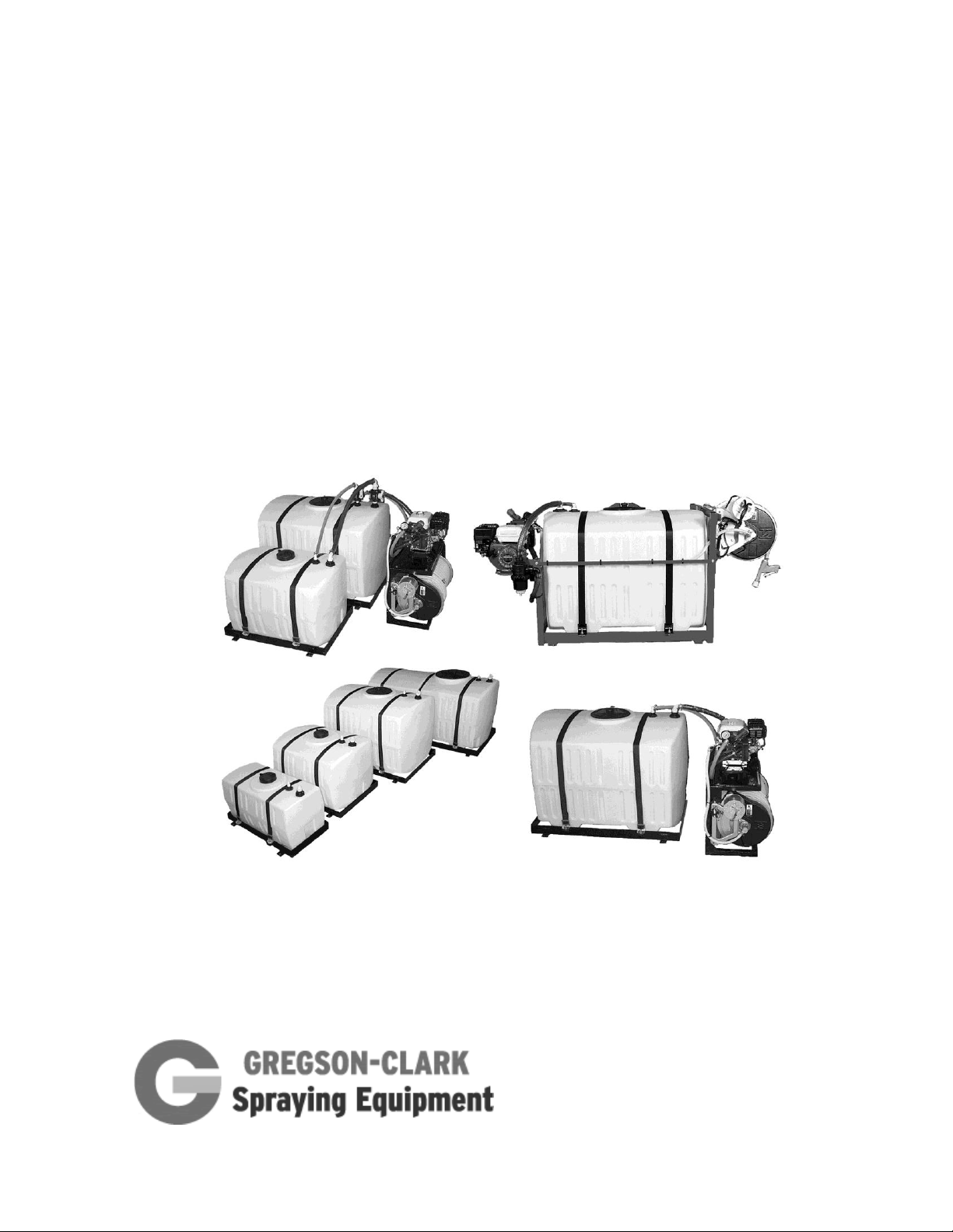
V-Series Sprayers and
Modular Systems
Operator’s Manual
Do not hesitate to call your dealer or Gregson-Clark directly with any questions or concerns.
We welcome your comments and suggestions on how we can continue to improve this product.
There are separate manuals for the hose reel, pump, and engine included with the sprayer.
Toll free: 800 . 706 . 9530 Fax: 585 . 538 . 9577
Phone: 585 . 538 . 9570 E-mail: Sales@GregsonClark.com
VSS 10-12

2
TABLE OF CONTENTS
Safety Precautions ............................................................................................................. 2
Set-Up and Assembly ......................................................................................................... 3
Start-up and Testing ........................................................................................................... 6
Overview of Operation ........................................................................................................ 8
Component Descriptions .................................................................................................... 9
Maintenance ....................................................................................................................... 13
Specifications ..................................................................................................................... 13
Troubleshooting ................................ ................................................................ .................. 14
About Diaphragm Pumps .................................................................................................... 15
Pump Service Guide ........................................................................................................... 16
Winter Storage .................................................................................................................... 18
Accessories ........................................................................................................................ 19
Warranty ............................................................................................................................. 21
SAFETY PRECAUTIONS
Pesticides can cause personal injury and harm the environment when used improperly. Be
sure to follow label recommendations concerning safety and disposal. Observe all safety
precautions including wearing protective clothing and equipment.
Calibrate and test using clean water.
Check before each use for leaks or damage.
Read and follow the label instructions of the products used.
NOTE:
V-Series skid sprayers and modular systems are available with many different component
options. The photos and information shown herein are intended to be general guidelines.
Please refer to the additional manuals provided for information regarding the specific
components of your sprayer or call us at 1-800-706-9530.
VSS 10-12

3
SET-UP AND ASSEMBLY
Check for apparent signs of shipping damage and that the order is complete. Carefully
uncrate the sprayer and report any freight damage or shortages. Claims must be within
five days of delivery. The sprayer was completely assembled and tested prior to
shipping. Some disassembly may have been required for shipping. Re-attach the reel
to the frame in the desired location. Mount the reel on the end opposite the pump for
use in pick-up trucks or under the pump when used in enclosed trailers or vans. (See
photos 1 & 2)
Photo 1 Reel mounted opposite pump. Photo 2 Reel mounted under pump
In a pick-up truck, the sprayer typically is mounted in the forward-most position against the
front wall of the truck bed. Secure the frame by bolting through the truck bed or by using a
ratchet strap if suitable anchoring locations are available. (See photo 3) Note that your skid
must be secured in compliance with your local Department of Transportation regulations.
Photo 3 Sprayer mounted in truck Photo 4 Wiring Harness
Do not exceed weight limitations of vehicle. The weight should be balanced left-to-right and
positioned for-and-aft to distribute the weight in accordance with the capacities of the
vehicle’s axles.
If the sprayer is equipped with an electric hose reel, install the quick-disconnect wiring
harness provided. (See photo 4) Once installed, the shorter section will stay with the sprayer
and the longer section will remain with the truck. When removing the sprayer from the truck,
simply pull the modular connectors apart. Refer to Diagram 1 (See page 4) and connect
according to the labels on the terminals at the ends of the harness cables.
VSS 10-12

4
When connecting the ground wire to the truck frame, be sure to clean the contact area down
Pushbutton
Reel Switch
30 Amp Circuit Breaker
Auto Reset
14–16 Gauge Wire
Solenoid
Reel Motor
Positive
Modular
Connectors
Truck Battery
6 Gauge Wire
Batt.
Aux.
Circuit Breaker
Modular Connectors
Ground to Reel
Ground to Frame
Vehicle Ground
6 Gauge Wire
Diagram 1 Electrical Connections
Ground to
Reel Frame
to bare metal to ensure a good contact. When a reel will not rewind, it is often due to a faulty
ground connection. Use extra care in protecting the wires from the exhaust system and any
moving parts. Avoid any sharp edges that could cut through the wire insulation.
VSS 10-12
5
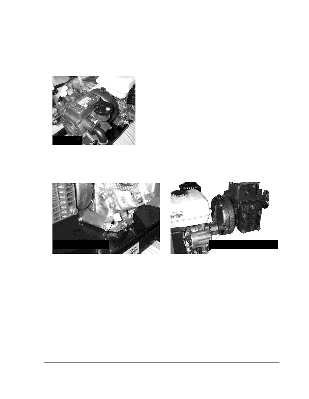
Set-Up and Assembly – Cont.
Oil Bowl
Engine Oil Dipstick
Pump Gearbox Side Plug
The engine oil, (SAE 10W30) gearbox oil, (SAE 80/90W) and pump oil (30W or 40W nondetergent) were added at the factory. The oil levels are as follows:
• Pump Crankcase – On the Kappa 43, 55 and Kappa 75 pump, the oil level is visible
in the oil bowl. (See photo 5) Other pump models may be slightly different.
Photo 5 Kappa 43, 55 & 75 Pumps
• Engine– The oil level should be up to the edge of the filler hole or at least to the tip
of the dipstick when inserted without screwing it into the filler neck. (See photo 6)
See the Honda Engine Owner’s Manual.
Photo 6 Engine Oil Dipstick Photo 7 Pump Gearbox Side Plug
• Pump Gearbox– The oil level should be up to the lower edge of the side-plug hole.
Do not overfill. (See photo 7)
VSS 10-12
6
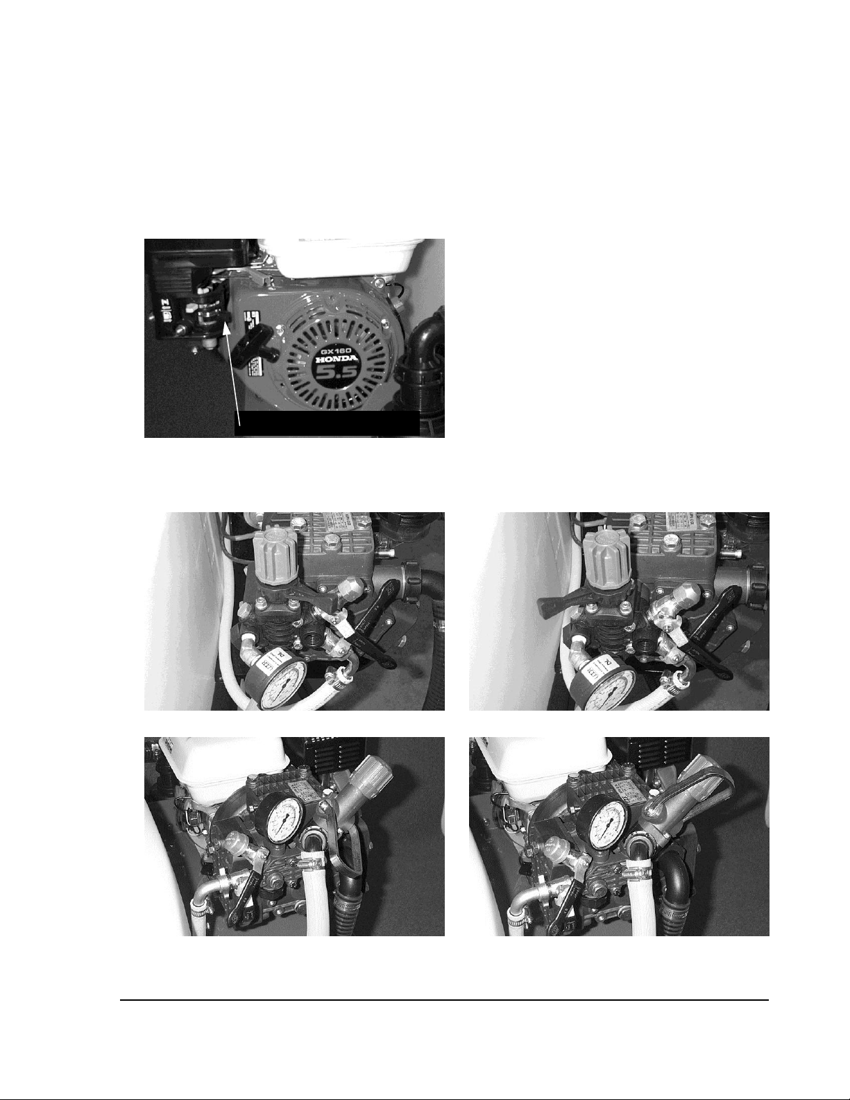
START-UP AND TESTING
Fuel Shut-off Valve lever
1. Re-attach the hoses to any modular tanks that were disconnected for shipping.
Note: The hoses may be longer than necessary; trim to length as required.
2. Ensure that suction strainer bowl is on tight.
3. Fill the spray tank 1/4 full of clean water.
4. Put gas in engine gas tank.
5. Turn on fuel shut-off valve lever on the carburetor. (See photo 8)
Photo 8 Fuel Shut-off
6. Recheck the engine oil level and check the oil in the pump and gearbox.
7. Put regulator lever in the Bypass position. (See photos 9 and 11)
Photo 9 Kappa 43 Pressure Regulator Bypass Position Photo 10 Kappa 43 Pressure Regulator Spray Position
Photo 11 Kappa 40/55/75 Pressure Regulator Photo 12 Kappa 40/55/75 Pressure Regulator
VSS 10-12
Bypass Position Spray Position

7
START-UP AND TESTING - CONT.
8. Turn engine switch on.
9. Choke engine.
10. Start engine and adjust throttle. Once engine is running and warmed up, un-choke the
engine.
11. Liquid should be visible after a few seconds as it moves through the suction hose. Liquid
agitation in the tank should also be visible. Run the engine at full throttle until there is no
air in the suction lines. Lower the engine speed to about 1/2 throttle.
12. Turn the regulator pressure-adjustment knob counter-clockwise until there is no longer
any resistance. Rotate the black plastic lever clockwise to the spray position.
(See photos 10 and 12) Slowly turn the adjustment knob clockwise. Note the increasing
pressure on the gauge. Adjust to the desired pressure for your application. (See photos
13 and 14)
Although the pump and engine can safely operate at full throttle, reducing the engine
speed to the minimum required for your application will ensure fuel savings and reduce
wear of the pump.
Photo 13 Kappa 43 Pressure Adjustment Photo 14 Kappa 40/55/75 Pressure Adjustment
13. Shut off the engine and clean the filter. There may be small plastic particles remaining
from the manufacturing process. See the Maintenance section (page 13) for instructions.
VSS 10-12

8
OVERVIEW OF OPERATION
Liquid is drawn from the tank and through the suction strainer by a positive displacement
diaphragm pump. Excess flow returns to the tank through a pressure regulator. The
returning flow provides agitation in the tank.
When the lever is in the bypass position, (See photos 9 and 11) the fluid returns to the tank
under no restriction, therefore the system is at very low pressure. Move the lever to the
bypass position when starting and shutting down the engine, when priming the pump, and
when maximum agitation is desired. All spraying is done when the lever is in the spray
position. (See photos 10 and 12)
Operating pressure is adjusted by turning the plastic knob on the regulator clockwise to
increase pressure and counter-clockwise to decrease pressure. Pressure is only achieved
when the lever on the regulator is in the spray position. (See photos 10 and 12)
It is important that all fittings on the suction side of the pump, particularly the suction
strainer, remain tight. Otherwise, the pump can draw air into the system and that will affect
performance. The pump fittings are sealed with O-rings and should not be over-tightened.
VSS 10-12

9
COMPONENT DESCRIPTIONS
Suction Tube
Assembly
Agitator Tube
Assembly
Tank Fitting
Assembly, Suction
Barb Elbow,
Suction
V-50 & 50B-SA
STA-20
AGIT-14, 14” Lg.
TF125
HB125-90
V-100 & 100B-SA
STA-20
AGIT-20, 20” Lg.
TF125
HB125-90
V-150 & 150B-SA
STA-26
AGIT-20, 20” Lg.
TF125
HB125-90
V-200 & 200B-SA
STA-35
AGIT-29, 29” Lg.
TF125
HB125-90
V-300 & 300B-SA
STA-37
AGIT-29, 29” Lg.
TF125
HB125-90
Tank Fitting
Assembly, Return
Barb Elbow,
Return
Elbow,
Agitator
Agitator
V-50 & 50B-SA
TF075
HB075-90
SE34
500262
V-100 & 100B-SA
TF075
HB075-90
SE34
500262
V-150 & 150B-SA
TF075
HB075-90
SE34
500262
V-200 & 200B-SA
TF075
HB075-90
SE34
500262
V-300 & 300B-SA
TF075
HB075-90
SE34
500262
Suction Tube
Assembly
Tank Fitting,
Suction
Barb Elbow,
Suction
Tank Fitting,
Return
Barb Elbow,
Return
Agitator Tube
Assembly
Agitator
Elbow
Tank Wall
Tank Connections
Part Numbers
Photo 15 Tank Connection Fittings
VSS 10-12

10
COMPONENT DESCRIPTIONS, CON’T.
Strainer Body
Only
(No Checkvalve)
Strainer Element
O-ring
Strainer
Element
Strainer Cup
Plug O-ring
Strainer Plug
3142060.010
314300.060
314001.030
3142400.020
462300.230
3142400.060
Fly Nut (x 2)
Hose Barb
O-ring (x 2)
Hose Barb
(x 2)
Cup O-ring
Strainer Nut
2002060
G10061
116633
314000.050
314000.040
Strainer Body
Strainer Element
Strainer Element
O-ring
Strainer Cup
Plug
Cup O-ring
Plug O-ring
Fly Nut (x 2)
Hose Barb (x 2)
Hose Barb O-ring (x 2)
Strainer Nut
Strainer Assembly with Barbs - P/N 3142561-A
Strainer Assembly without Barbs - P/N 3142561
Part Numbers
Photo 16 Strainer Parts
VSS 10-12

11
COMPONENT DESCRIPTIONS, CON’T.
Bypass Hose, *
3/4"
Hose Clamp,
Bypass
Suction Hose, *
1-1/4”
Hose Clamp,
Suction
Hose to Reel, *
1/2"
Hose Clamp,
Hose to Reel
A-1628-3/4
20J
K-125
20J
A-1661-1/2X1
10J
Hose Barb,
Bypass,
3/4"
O-ring,
Bypass
Nut,
Bypass
Hose Barb, 1/2"
Hose to Reel,
Includes Nut
and Gasket
Gasket,
Hose to Reel
Hose Barb,
Suction,
1-1/4”
O-ring,
Suction
Nut,
Suction
0254.04
1101.12
0604.26
163.604.6
0605.05
0202.52
1101.41
0604.18
Bypass Hose
Hose Barb, Hose to Reel
Suction Hose
Hose Barb, Suction
Hose Clamp x2
Hose Clamp x 2
Hose Clamp x 2
Hose Barb, Bypass
Hose to Reel
Pump Connections
Photo 17 Pump Connections
Part Numbers
* Hose lengths may vary
Photo 18 Connection Fittings
VSS 10-12

12
COMPONENT DESCRIPTIONS, CON’T.
Kit
Strap (2)
Clamp (4)
Hex Bolt (4)
Hex Nut (4)
Washer (4)
TDK-50
TS198 x 9.4, 64” Lg
TD-200
0115110
1137185
1133859
TDK-100
TS198 x 12.9, 77” Lg
TD-200
0115110
1137185
1133859
TDK-150
TS198 x 12.0, 80” Lg
TD-200
0115110
1137185
1133859
TDK-200
TS198 x 16.8, 98” Lg
TD-200
0115110
1137185
1133859
TDK-300
TS198 x 16.8, 98” Lg
TD-200
0115110
1137185
1133859
Tank
Size
Lid, Vented
50 Gallon PCO Style
8”
10525
100 Gallon PCO Style
8”
10525
150 Gallon PCO Style
12”
10527
200 Gallon PCO Style
12”
10527
300 Gallon PCO Style
16”
10528
8” Lid
12” Lid
16” Lid
Tank Strap Kits
Photo 19 Tank Strap
Part Numbers
Tank Lids
Part Numbers
Photo 20 Tank Lids
VSS 10-12

13
MAINTENANCE
Check and tighten all hose clamps.
Check for worn hoses. (rubbing, cracking)
Check Engine air filter, clean every 50 hours; change every year or 300 hours.
Check Engine oil with each use, change after 20 hours and every 100 hours thereafter.
Check Pump oil with each use, change every year or 500 hours.
Check Pump Gearbox oil with each use, change after 20 hours and every 100 hours
thereafter.
Clean Suction Strainer. (See photos 21 and 22)
SPECIFICATIONS
Engine Crankcase Oil ......................................................... 10W30 (SJ or SL)
Engine Fuel Recommendation ............................................ 86 Octane (Min) unleaded
Pump Crankcase Oil ........................................................... 30 Wt. or 40 Wt. Non-detergent
Pump Gearbox Oil .............................................................. 80W90 Gear Oil
Photo 21 Suction Strainer Photo 22 Center Post
The suction strainer is equipped with an internal shut-off valve that closes when the
cup is removed. It prevents the suction line from emptying when the strainer is
dissembled for cleaning.
IMPORTANT!
When re-assembling the strainer, ensure that the center post in the cup engages the
steel pin in the strainer head. (See photo 22) Otherwise, the valve will remain closed
and damage to the pump may result.
VSS 10-12

14
TROUBLESHOOTING
Problem
Possible cause
Solution
Low or no pressure or
Valve in suction strainer closed
Verify cup alignment with valve stem
Pump does not prime
See page 12
Plugged strainer
Clean screen
Plugged suction hose
Clear obstruction
- Check top of strainer for debris
Faulty or missing o-rings in Strainer
Replace o-rings
Assembly or pump Inlet Elbow Barb
Air leak in pump suction hose
Check hoses and fittings for leaks
Stuck or worn pressure relief valve on
Repair or replace relief valve
regulator
Low liquid level in tank
Refill tank
Improperly seated check valve(s) in
Clean or replace check valve
pump head
Fluctuating pressure
Pulsation dampener pressure incorrect
Adjust pulsation dampener pressure
(Excessive pulsation
-Should be at 20% of operating pressure
of Hoses)
Pump not purged of air
Run pump with regulator in the bypass
position to purge air
Defective regulator
Repair or replace regulator
Diaphragm Pumps
Pump oil has milky color
Ruptured diaphragm(s) in pump
Repair as necessary
Pump oil level low
VSS 10-12
Table 1

15
ABOUT DIAPHRAGM PUMPS
How the pump works
The diaphragm is what separates the pump oil from the spray solution. Each piston
down-stroke lowers the piston-attached diaphragm, drawing spray solution into the
pump head. As the piston passes below the cylinder sleeve side openings, oil is pulled
into the lower diaphragm cavity. During each piston up-stroke, the cushion of oil
between the piston and the diaphragm hydraulically pushes and cushions the
diaphragm as the piston tops out. This discharges the solution from the pump head.
The lower diaphragm cavity oil cushion also lubricates the diaphragm and pistons,
ensuring minimal mechanical wear.
Remember – low crankcase oil level causes excessive mechanical wear on
diaphragms and internal components. The transparent oil bowl makes checking the oil
easy. Keep the oil filled to the mark on the bowl.
Do not run the pump with a starved suction
The diaphragm pump will not suffer any damage if run dry due to an empty tank.
However, a starved suction due to a clogged suction strainer or a closed suction valve
will cause premature failure of the pump diaphragms.
Note – Only use filter screens that are between 16 and 20 mesh. Never use a fine filter
screen on a diaphragm pump.
Pulsation Dampeners
It is the nature of diaphragm pumps to have some pulsation. It is caused by the
sudden changes in the piston direction. The pulsation dampener reduces pulsation by
providing a cushion of air for the piston to bump against. The UDOR pulsation
dampener uses a rubber bladder to separate the air cushion from the solution being
pumped.
Pulsation Dampener Setting
The basic rule is to inflate the pulsation dampener to 20% of the systems’ working
pressure. For example, if the spraying pressure is set at 100 psi, the pulsation
dampener should be inflated to 20 psi.
Always shut down the pump before adding air to the pulsation dampener or checking
its pressure. Air pressure can be supplied from a compressor or a manual air pump.
The diaphragm dome contains a very small volume of air. Take care when checking
the air pressure that a minimum amount of air leaks out when the pressure gauge is
applied to the air valve. It is possible to lose 5–10 psi when checking the pulsation
dampener air pressure.
Note: Two-cylinder diaphragm pumps may require more air pressure than 20% of the
operating pressure. The minimum pulsation dampener air pressure is 20 psi.
DO NOT run two-cylinder pumps with less than 20 psi in the pulsation dampener.
VSS 10-12

16
SERVICE GUIDE FOR REPLACING PUMP DIAPHRAGMS
1. Drain Crankcase Oil – drain pump crankcase by removing the oil drain plug located
at the bottom of the pump, also remove the oil fill cap or plug.
Note: On older pump models that do not have the oil drain plug, oil will need to be
drained after the head diaphragm and piston sleeve have been removed.
Note: When re-installing piston sleeves, the oil holes must always be aligned
parallel with the pump crankshaft.
2. External Manifold Removal – if your pump has external manifolds, they must be
removed prior to head removal.
3. Head Removal – remove the head bolts, then, remove the pump heads, which may
require some “light” prying.
4. Diaphragm Removal – turn the crankshaft to bring the piston up to the top of its
stroke, remove the diaphragm bolt and washer, and remove the diaphragm.
5. Crankcase Cleaning – to properly clean the crankcase, remove the piston sleeves
and wash the crankcase with a parts-washing solution or equivalent. Before reinstalling the piston sleeves, apply a light coating of oil to the pistons and sleeves.
Note: Make sure the oil holes in the piston sleeve are aligned parallel to the pump
crankshaft.
6. Installing New Diaphragms – install the diaphragm bolt and washer into the new
diaphragm. Install this assembly to the piston with the flat side of the diaphragm
down. Use blue thread locker or equivalent on the diaphragm bolt. Tighten the
bolts to the recommended torque specs. Rotate the crankshaft to bring the piston
and diaphragm to the bottom of its stroke and then seat the outside edge of the
diaphragm into the pump body.
7. Installing Head – it is very important to ensure that the check valves are installed
correctly when reinstalling the pump head. There are two valves for each cylinder;
one valve lets the solution into the head, the other valve lets the solution out of the
head. Tighten the pump head bolts to the recommended torque specs.
8. Installing Pulsation Dampener Diaphragm – bleed off the air in the chamber and
remove the cover bolts, cover, and diaphragm. Install the new diaphragm with the
dome down. Reinstall the cover and tighten the bolts to recommended torque
specs. Recharge the pulsation dampener with compressed air to 20% of the
pumps operating pressure.
9. Refilling Pump Crankcase – check the oil drain plug, making sure that it is installed
in the crankcase. Fill the pump with UDOR LUBE premium pump oil or SAE 30 or
40-weight non-detergent oil to the recommended mark on the oil sight glass/gauge,
about halfway on the oil sight glass/gauge. Rotate the crankshaft while filing to
eliminate air pockets.
10. Initial Start Up – run the pump for five minutes under no load conditions. This will
evacuate any remaining air pockets in the crankcase. Turn the pump off and recheck oil level. Refill as necessary to proper oil level.
IMPORTANT During initial startup, monitor the oil color. If it turns milky white, the
diaphragms were not seated or installed correctly.
VSS 10-12

17
Torque Specifications for UDOR Diaphragm Pumps
All values are in Foot-Pounds unless otherwise noted.
Diaphragm
Bolts
(Use Blue
Loctite™
Head
Bolts
Valve
Caps
Inlet
Manifolds
and Inlet
Manifold
Covers
Discharge
Manifolds
(Brass/Aluminum)
Discharge
Manifolds
(Plastic)
Pulsation
Dampener
KAPPA
7, 15, 18
8
10 N/A N/A N/A
N/A 10
KAPPA
33, 35, 43,
55, 75, 100
18
28 N/A 6
(72 In/Lbs)
N/A
N/A 28
(KAPPA
100 = 20
Ft/Lbs)
KAPPA
30, 40, 50
18
28 N/A N/A N/A
N/A 28
KAPPA
120, 150
25
32 N/A 6
(72 In/Lbs)
N/A
N/A 20
RO Series
Pumps
25
28 N/A 5
(60 In/Lbs)
18
RO 106/121
Only
5
(60 In/Lbs)
18
IOTA – 17
8
15 4.2
(50 In/Lbs)
N/A N/A
N/A 15
ZETA
85, 100
18
28 N/A 5
(60 In/Lbs)
N/A
5
(60 In/Lbs)
18
Table 2
WARNING
Be sure to follow the above torque specifications when reassembling diaphragms.
Overtightening of the diaphragm bolts can strip the threads in the aluminum pistons. This will
require a complete new assembly or a replacement of the pump.
VSS 10-12

18
WINTER STORAGE
Clean the tank with soap and water. Pump some of the soap solution through the hose
and gun by spraying the gun into the tank through the top opening. Empty the tank and
partially refill with clean water. Flush out the hose and gun, and spray the exterior of
the tank and other components that were exposed to chemicals. Empty the tank
completely. Dispose of rinse fluids in accordance with all applicable regulations.
Add undiluted RV anti-freeze through the suction strainer. (See photo 20) Circulate the
anti-freeze solution through the pump regulator. Blow out the reel and hose with
compressed air or pump undiluted RV anti-freeze completely through the hose.
Empty the suction strainer.
For more information on winterizing your sprayer, refer to our Web site.
www.GregsonClark.com/resource_info.html
Photo 23 Add Anti-Freeze through Suction Strainer
VSS 10-12

19
ACCESSORIES
Eco-505 Injection Spraying System
The Eco-505 Injection System is an add-on
accessory for a turf spraying system that
injects pesticide into the fertilizer stream on
demand. The dual trigger spray gun and
coaxial hose provide a means of
minimizing unnecessary application and
eliminating the need for spot spraying in a
secondary operation.
Modular Tank Assemblies
Modular tank assemblies provide an
expandable, portable, versatile
solution to accommodate a wide
variety of needs.
High-Pressure Strainer
The high-pressure Strainer is mounted
between the reel and the pump. It is selfcleaning by means of an included flush
valve mounted on the bottom of the strainer
body.
The strainer eliminates the need for
repeated cleaning of your gun nozzle by
removing contaminates before they reach
the gun.
Strainer Bags
The Strainer Bag is ideal for mixing dry
fertilizers and chemicals in jet agitation
sprayers. The strainer bag can hold a full
bag of urea, saving mixing time and
preventing potential plugging of the suction
strainer or pump. The lid may be closed
while the bag is in place.
VSS 10-12

20
WARRANTY
Gregson-Clark Sprayers are warranted by the manufacturer to the original purchaser to be free
from defects in materials and workmanship for a period of one year. The pump elastomers and
hoses are considered normal wear items and carry a 90-day warranty against defects in
materials and workmanship.
Gregson-Clark’s liability shall be limited to replacement of defective components, FOB shipping
point. In no event shall Gregson-Clark be liable for any special, incidental, or consequential
damages including loss of profits.
Toll free: 800 . 706 . 9530 Fax: 585 . 538 . 9577
Phone: 585 . 538 . 9570 E-mail: Sales@GregsonClark.com
Web: www.GregsonClark.com
VSS 10-12
 Loading...