

Gregory TTMA-100 Assembly Manual

TTMA-100
Assembly Manual
4100 13th Street, SW • Canton, Ohio 44710 • Phone 330-477-4800
i
Gregory Industries, Inc.
www.gregorycorp.com
June 2010

FOREWORD
Thank you for your purchase of the Trailer Truck Mounted Attenuator, Model 100, from
Gregory Industries, Inc. (herein referred to as the TTMA-100). The TTMA-100 is a Test Level 3
(TL-3) crash cushion designed for use with a support truck in both stationary and moving work
zones. We are committed to providing our customers with highway safety products that have the
best performance and value for your money, as well as the highest level of customer service. The
TTMA-100 is one of the most innovative TMA’s in the market, offering a higher level of
performance with heavy tow vehicles and requiring no modification of the tow vehicle. It has
successfully passed all required and optional crash tests set forth in NCHRP Report 350 and is
fully approved for use on the National Highway System by the Federal Highway Administration.
This manual provides step-by-step instructions on the assembly of the TTMA-100 and applies to
both initial assembly and repair and replacement of damaged components. Please read and
understand the recommendations contained in this manual thoroughly before actual assembly,
and keep it handy for future reference. If you have any questions or comments regarding the
operation and maintenance of this product, please contact us by telephone 330-477-4800 or by
mail at Gregory Industries, Inc. 4100 13th Street, SW, Canton, Ohio 44710. Technical issues
can be emailed to TTMATechnicalSupport@gregorycorp.com
This manual is divided into four sections:
• TTMA Design and Major Components. An overview of the Trailer TMA design and
major components are presented in this section, including the product specifications and
parts list.
• General Instructions. Some general information regarding assembly of the TTMA-100,
such as shipping package, recommended tool list, bolt torque specifications, pintle hook,
and removal of excess zinc.
• Assembly Instructions. Step-by-step instructions on the assembly of the TTMA-100 are
outlined and illustrated in this section.
• Repair of Damaged Trailer. Discussions of impacts by an errant vehicle and the
associated repair and replacement of trailer parts are presented in this section.
ii

CUSTOMER SERVICE CONTACTS
Gregory Industries, Inc. is committed to providing the best service and care to our customers.
You are automatically registered with your purchase and you will be notified of any future
changes or upgrades to the TTMA-100. If you have any comments or questions regarding this
product, please contact Gregory Industries via telephone, e-mail or conventional mail:
Telephone (330)-477-4800; Monday to Friday, 9:00 a.m. to 5:00 p.m. Eastern Standard Time.
Email: TTMATechnicalSupport@gregorycorp.com
Web Site: http://www.gregorycorp.com
Mail: Gregory Industries, Inc.
4100 13th Street, SW
Canton, Ohio 44710
iii

TABLE OF CONTENTS
Page
FOREWORD . . . . . . . . . . . . . . . . . . . . . . . . . . . . . . . . . . . . . . . . . . . . . . . . . . . . . . . . ii
CUSTOMER SERVICE CONTACTS . . . . . . . . . . . . . . . . . . . . . . . . . . . . . . . . . . . . iii
TTMA-100 DESIGN AND MAJOR COMPONENTS . . . . . . . . . . . . . . . . . . . . . . . . 1
General . . . . . . . . . . . . . . . . . . . . . . . . . . . . . . . . . . . . . . . . . . . . . . . . . . . . . . . 1
Figure 1. Schematic and Parts Layout of TTMA-100 . . . . . . . . . . . . . . . . . . 2
Table 1. General Specifications. . . . . . . . . . . . . . . . . . . . . . . . . . . . . . . . . . 3
Table 2. Trailer Component and Parts List . . . . . . . . . . . . . . . . . . . . . . . . . . 4
Figure 2. TTMA-100 Wiring and Light Layout . . . . . . . . . . . . . . . . . . . . . . 5
GENERAL INSTRUCTIONS . . . . . . . . . . . . . . . . . . . . . . . . . . . . . . . . . . . . . . . . . . . 6
Shipping Package . . . . . . . . . . . . . . . . . . . . . . . . . . . . . . . . . . . . . . . . . . . . . . . 6
Recommended Tool List . . . . . . . . . . . . . . . . . . . . . . . . . . . . . . . . . . . . . . . . . 6
Bolt Torque Specifications . . . . . . . . . . . . . . . . . . . . . . . . . . . . . . . . . . . . . . . . 6
Pintle Hook . . . . . . . . . . . . . . . . . . . . . . . . . . . . . . . . . . . . . . . . . . . . . . . . . . . . 7
INSTALLATION INSTRUCTIONS . . . . . . . . . . . . . . . . . . . . . . . . . . . . . . . . . . . . . 8
Layout of Major Components . . . . . . . . . . . . . . . . . . . . . . . . . . . . . . . . . . . . . 8
Connect Energy Absorbing Tubes to A-Frame. . . . . . . . . . . . . . . . . . . . . . . . . 10
Insert Connecting Block for Axle and Fender Assembly . . . . . . . . . . . . . . . . . 12
Install Mandrels . . . . . . . . . . . . . . . . . . . . . . . . . . . . . . . . . . . . . . . . . . . . . . . . 14
Attach Impact Head . . . . . . . . . . . . . . . . . . . . . . . . . . . . . . . . . . . . . . . . . . . . . 14
Align and Tighten Connections between Energy Absorbing Tubes
and A-Frame . . . . . . . . . . . . . . . . . . . . . . . . . . . . . . . . . . . . . . . . . . . . . . . . 13
Assemble Axle, Fenders, and Wheels and Tires . . . . . . . . . . . . . . . . . . . . . . . 14
Install Light Bar . . . . . . . . . . . . . . . . . . . . . . . . . . . . . . . . . . . . . . . . . . . . . . . . 14
Install Accessories on A-Frame . . . . . . . . . . . . . . . . . . . . . . . . . . . . . . . . . . . . 10
Install Chevron Panels and Conspicuity Tapes . . . . . . . . . . . . . . . . . . . . . . . . 10
REPAIR INSTRUCTIONS . . . . . . . . . . . . . . . . . . . . . . . . . . . . . . . . . . . . . . . . . . . . . 17
Impact by Errant Vehicle . . . . . . . . . . . . . . . . . . . . . . . . . . . . . . . . . . . . . . . . . 17
TTMA-100 Repair . . . . . . . . . . . . . . . . . . . . . . . . . . . . . . . . . . . . . . . . . . . . . . 19
Damage Assessment and Repair Parts Packages . . . . . . . . . . . . . . . . . . . . . . . 19
No Apparent Damage to Trailer . . . . . . . . . . . . . . . . . . . . . . . . . . . . . . . . 20
Axle Assembly Not Detached . . . . . . . . . . . . . . . . . . . . . . . . . . . . . . . . . 20
Axle Assembly Detached, but No Damage to Trailer A-Frame . . . . . . . . 21
Bursting Reaches Trailer A-Frame . . . . . . . . . . . . . . . . . . . . . . . . . . . . . . 22
Repair Instructions . . . . . . . . . . . . . . . . . . . . . . . . . . . . . . . . . . . . . . . . . . . . . 17
Technical Assistance . . . . . . . . . . . . . . . . . . . . . . . . . . . . . . . . . . . . . . . . . . . . 22
iv

TTMA-100 DESIGN AND MAJOR COMPONENTS
GENERAL
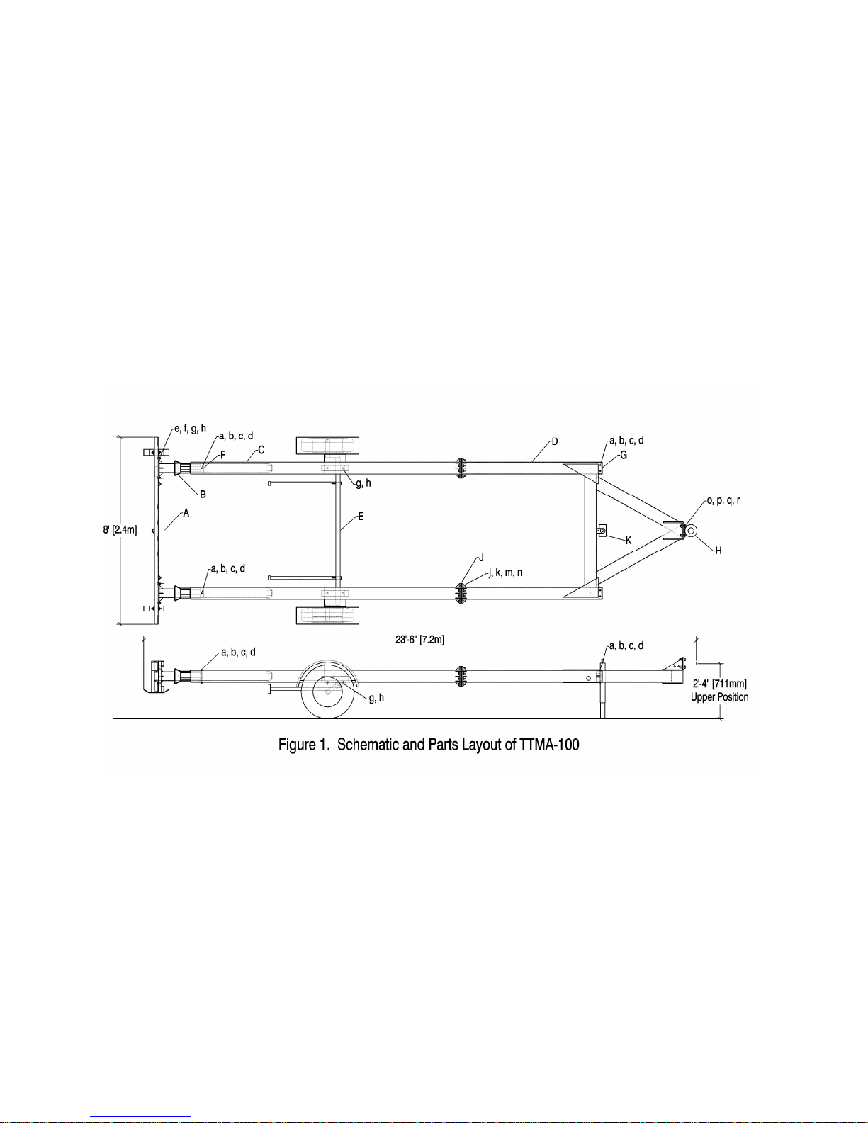
A schematic of the TTMA-100 is shown in Figure 1. The major components of the TTMA-100,
as shown in Figure 1, are as follows:
Component
A Impact Head
B Bursting Mandrel
C First Energy Absorbing Tube
D Trailer Frame
E Axle Assembly
F Plastic Guide Plates
K Jack Assembly
Table 1 presents the general specifications for the Trailer TMA, including:
• Overall dimensions, i.e., length, width and maximum height to the top of the impact head
and the top of the light bar
• Weight of the trailer with no optional equipment and the tongue weight. Note the small
tongue weight of the trailer, which would not affect the load carrying capacity of the tow
vehicle.
• The capacity and mounting height of the pintle hook.
• Information on the axle assembly, i.e., load rating, wheel and tire sizes, and cold inflation
pressure.
Table 2 provides a list of parts with legends and part numbers. Please refer to these part numbers
and legends for ordering of spare parts. Note that this is not a complete parts list. Please inquire
about the complete parts list and pricing from the manufacturer, distributor, or reseller of the
Trailer TMA.
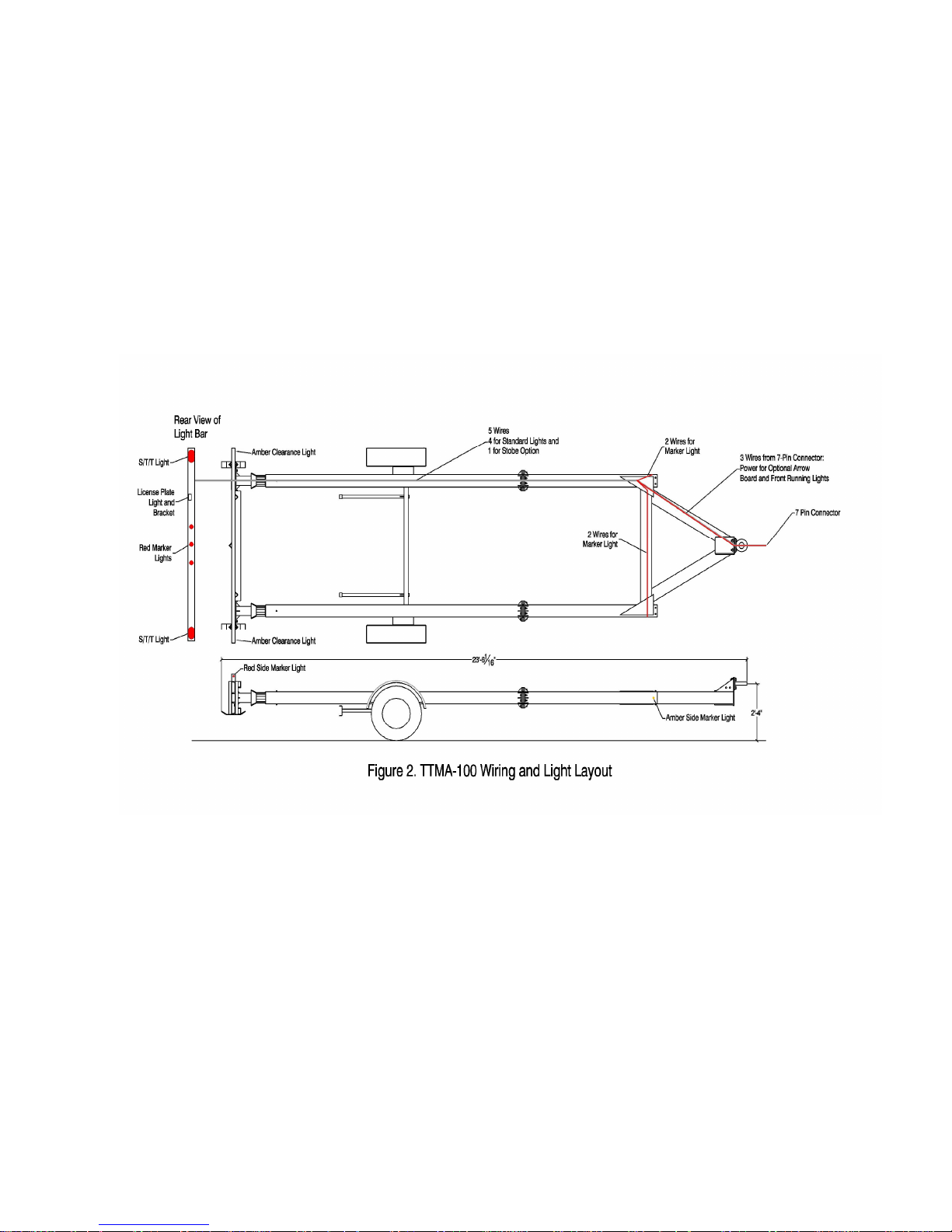
Figure 2 shows the schematic of the wiring details of the Trailer TMA. Also, detailed
instructions on the wiring of the trailer TMA are provided in a separate Wiring Manual and will
not be repeated herein.
Description
G End Caps
H Hitch Assembly
J Spacer
1
2

TABLE 1. GENERAL SPECIFICATIONS
Overall Dimensions:
Length 23 ft 6 in.
Width 8 ft 0 in.
Maximum Height (to top of impact head) 31 in.
Maximum Height (to top of light bar) 37 in.
Ground Clearance (to bottom of impact head) 13 in.
Weight:
Basic Trailer Weight with No Optional Equipment 1,450 lb
Approximate Tongue Weight 190 lb
Pintle Hook:
Capacity Rating (Minimum) 8 tons
Mounting Height 19.5-32.0 in.
Breakaway Axle:
Rating 1,750 lb
Tire Size 205/75D15
Rim Size 15x5JJ
Cold Tire Inflation Pressure 30 psi
3

TABLE 2. TRAILER COMPONENT AND PARTS LIST
TRAILER COMPONENTS
ITEM PART # QUANTITY DESCRIPTION
A T100A 1 Impact Head
B T100B 2 Bursting Mandrel
C T100C 2 First Stage Energy Absorber
D T100D 1 Trailer A-Frame
E T100E 1 Axle Assembly
F T100F 4 Plastic Guide Plates
G T100G 2 End Caps
H T100H 1 Hitch Assembly
J T100J 8 Spacer
K T100K 1 Jack Assembly
HARDWARE ITEMS
ITEM PART# QUANTITY DESCRIPTION
a B0516070A 6 5/16” x 7” Grade 5 Hex Bolt
b W0516 6 5/16” Washer
c LW0516A 6 5/16” Heavy Lock Washer
d N0516A 6 5/16” Grade 5 Hex Nut
e B0816020A 8 1/2” x 2” Grade 5 Hex Bolt
f W0816 8 1/2” Washer
g LW0816A 12 1/2” Heavy Lock Washer
h N0816A 12 1/2” Grade 5 Hex Nut
j B0916030A 16 9/16” x 3” Grade 5 Hex Bolt
k W0916S 16 9/16” SAE Washer
m LW0916A 16 9/16” Heavy Lock Washer
n N0916A 16 9/16” Grade 5 Hex Nut
o B1016025A 4 5/8” x 2 1/2” Grade 5 Hex Bolt
p W1016 4 5/8” Washer
q LW1016A 4 5/8” Heavy Lock Washer
r N1016A 4 5/8” Grade 5 Hex Nut
4
5

GENERAL INSTRUCTIONS
SHIPPING PACKAGE
This manual is intended for the assembly of the TTMA-100. Note that the unit may be shipped in
different stages of assembly, depending on the order. Similarly, when repairing a damaged
trailer, the extent of disassembly and re-assembly would vary depending on the nature and extent
of repair and the parts that need to be replaced. Thus, the instructions cover the entire assembly
process, with the exception of wiring, even though only part of the instructions may be
applicable in any given situation.
RECOMMENDED TOOL LIST
The following is the recommended tool list for assembling the TTMA-100:
• Socket wrenches: ½”, ¾”, 13/16”, 15/16”
• Open end wrenches: ½”, ¾”, 13/16”, 15/16”
• Pneumatic wrench
• Drift pin
• Wire crimper
• Round and flat metal files
• Electric drill and bits
• 4-ft level
• Measuring tape
Optional:
• Fork lift/crane for parts manipulation. Note that some parts are very heavy and care
should be taken in assembling and disassembling the unit.
BOLT TORQUE SPECIFICATIONS
All bolts should be tightened to the specified torque prior to use of the Trailer TMA. The
following are the recommended torques to the bolts according to the bolt size:
Bolt Size (in) 5/16” 1/2” 9/16” 5/8”
Torque (ft-lb) 15 60 85 115
Torque (N-m) 20 81 115 156
6
PINTLE HOOK ASSEMBLY
The pintle hook should have a minimum capacity rating of 8 tons. Due to the wide variations in
the frame structures of different tow vehicles, there is not a single standard means of mounting
the pintle hook assembly to the frame of the tow vehicle. The major considerations in mounting
of the pintle hook are the strength of the attachment and the mounting height.
The pintle hook assembly may be welded or bolted to the frame of the tow vehicle. Regardless of
the method of mounting or attachment to the tow vehicle, it is critical to ensure that the strength
of the attachment exceeds the rated capacity of the pintle hook with a wide margin of safety. It is
the obligation of the users to ensure that their particular pintle hook attachment system
meets these strength requirements.
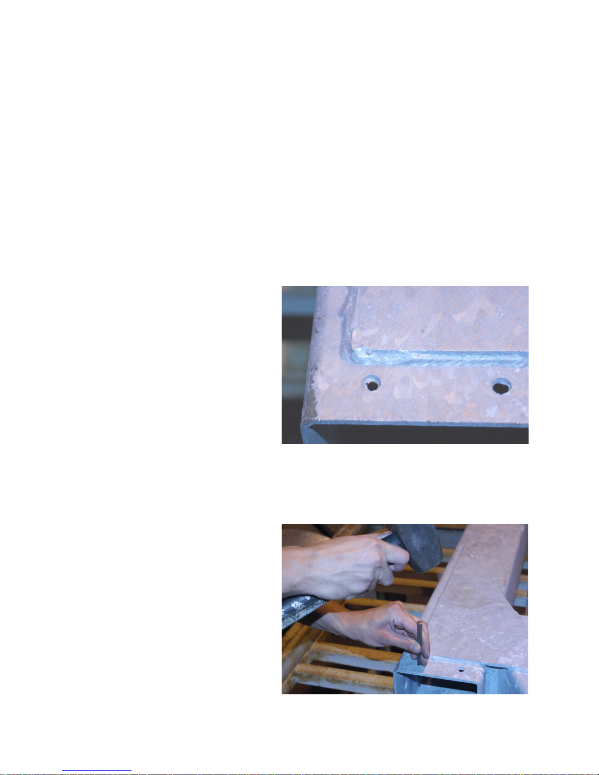
CLEARING OF EXCESS ZINC
• All the major components of the
TTMA-100 are galvanized to
protect the metal from the
weather elements. It is not
unusual for some of the holes to
have excess zinc as a result of the
hot-dip process, as shown in the
photograph.
The excess zinc would effectively reduce the size of the hole so that the bolt would not fit
through the hole. It is, therefore, necessary to remove excess zinc from the pre-drilled holes.
Depending on the excess amount of zinc, punching through the hole with a drift pin may be
sufficient; otherwise, an electric drill may be necessary, as shown in the following photographs.
• Use drift pin to remove excess
zinc.
7

• Use electric drill pin to remove
excess zinc.
8

INSTALLATION INSTRUCTIONS
The trailer can be assembled from scratch by two men in about 2 to 4 hours. Depending on the
shipping package, the trailer may already be partially assembled and certain steps in the
assembly process are, therefore, not applicable. However, all the steps of the assembly process
are shown for information purposes, in case the trailer has to be disassembled and reassembled.
Warning! Part D, the trailer frame, is too heavy for two men to move safely. It is
recommended that a lifting device be utilized to move the heavy parts.
Warning! Various parts of the trailer are heavy. Care in lifting should be exercised and
steel-toed boots are recommended.
Warning! The parts of trailer may have sharp asperities from the welding and
galvanizing processes. Use of appropriate gloves is recommended.
The major steps in the assembly of the trailer are as follows:
A. Arrange major components in approximate positions for assembly.
B. Connect energy absorbing tubes to A-frame.
C. Insert connecting block for axle and fender assembly.
D. Install mandrels.
E. Attach impact head.
F. Align and tighten connections between energy absorbing tubes and A-frame
G. Assemble axle, fenders, and wheels and tires.
H. Install light bar.
I. Install accessories.
J. Install chevron panels and conspicuity tapes.
More detailed descriptions of these major steps are presented in the following sections. A
separate section on wiring instructions is provided and will not be provided herein.
9
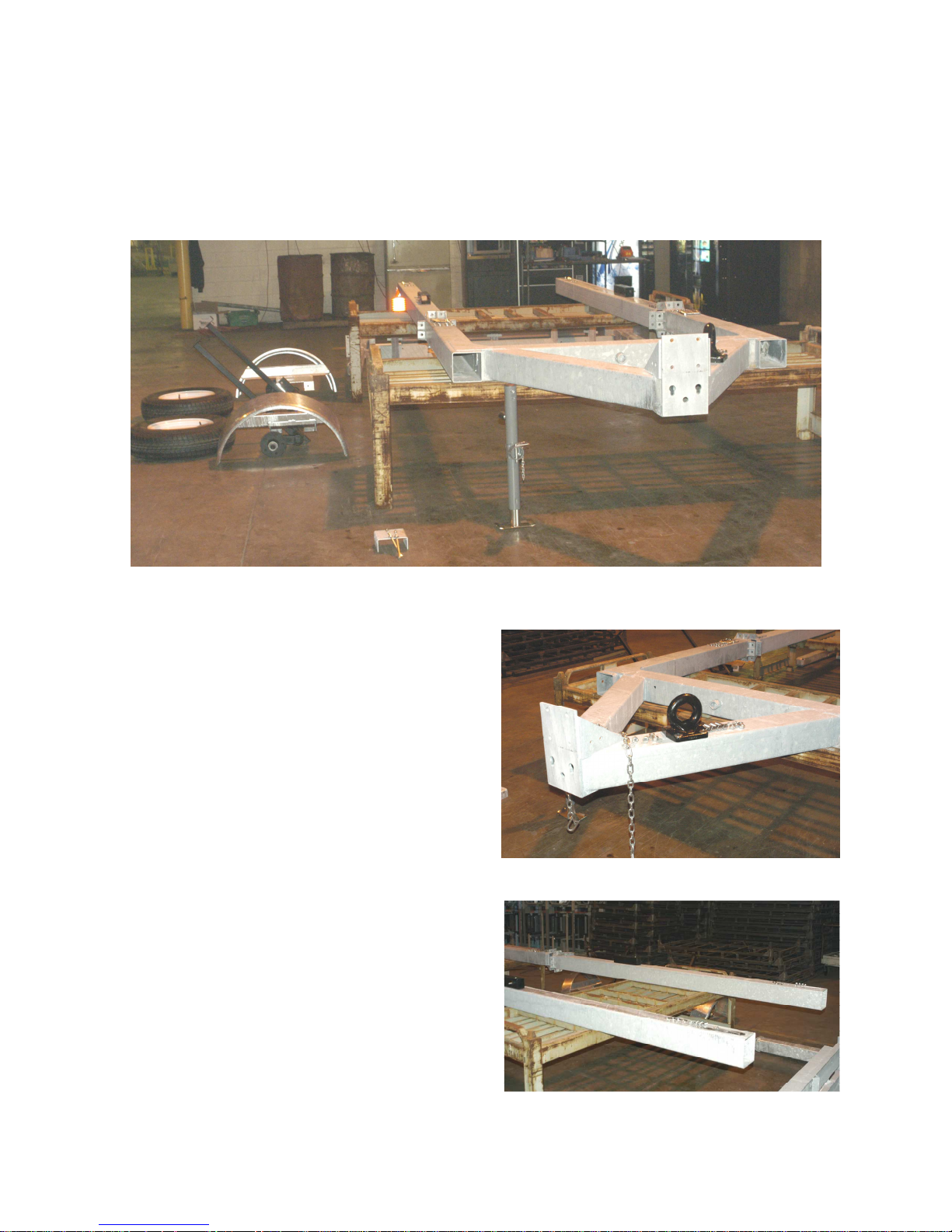
A. LAYOUT OF MAJOR COMPONENTS
Place the major components of the trailer in their approximate positions for assembly, as shown
in the following photograph. Note that the A-frame and the first energy absorbing tubes should
be placed on benches.
The following are close-up photographs of each major component:
• A-frame with lunette ring and safety
chains.
• Energy absorbing tubes.
10
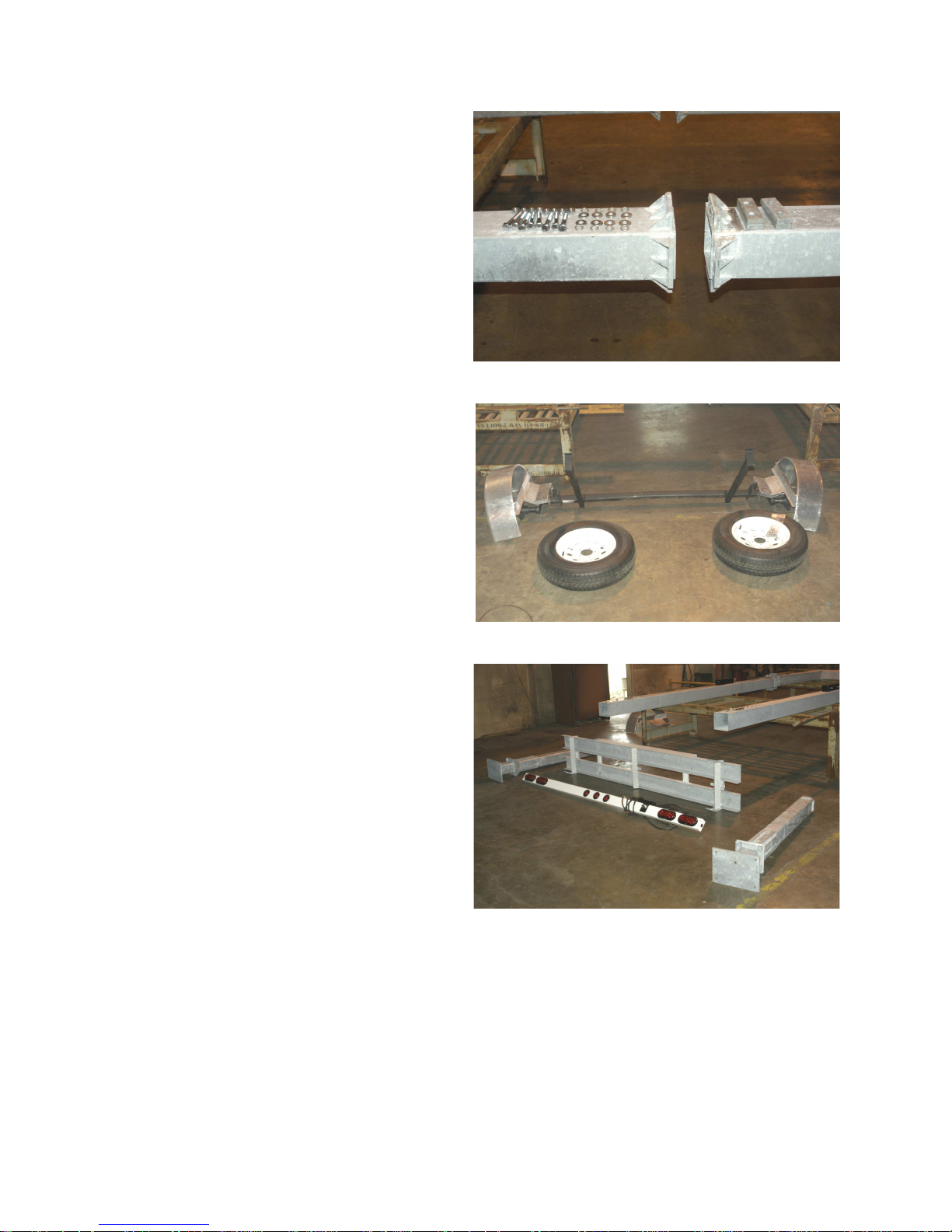
• Connection between energy
absorbing tubes and A-frame.
• Axle assembly with push rods,
fenders, and wheels and tires.
• Impact head, mandrels and light
bar assembly.
11
 Loading...