

GREER Company MICROGUARD 434 Troubleshooting Manual
MICROGUARD® 434
RATED CAPACITY LIMITER
SYSTEM
TROUBLESHOOTING
MANUAL
MicroGuard® 434 System — Troubleshooting Manual PN W434800 Rev D 09/19/06
1

The Greer Company
The Greer Company is dedicated to the design and
manufacture of electronic parts created to aid in crane
operation and in the protection of crane operators and
associated personnel. The following manual has been
developed to assist in helping Service Personnel to
understand, locate, and identify problems that may
®
arise during the operation of the MicroGuard
434
Rated Capacity Limiter System. Persons using this
Manual must be familiar with this System and
with Electrical Servicing. Use of calibration routines
without consultation with the Greer Company
invalidates the warranty.
MicroGuard® 434 System — Troubleshooting Manual PN W434800 Rev D 09/19/06
2

TABLE OF CONTENTS
MicroGuard ®434
Rated Capacity Limiter System
TROUBLESHOOTING MANUAL
Introduction
SERVICE DEDICATION..................................................................INSIDE FRONT COVER
WHERE TO GO FOR HELP.............................................................................................
SYSTEM DIAGRAM...........................................................................
INSIDE BACK COVER
4
Section I
PREPARATION ................................................................................................................ 5
Section ll
PROBLEM FINDER TABLES ........................................................................................... 7
Section III
SYSTEM INSTALLATIONS ..............................................................................................23
Section IV
SYSTEM COMPONENTS AND ASSOCIATED FUNCTIONS........................................ 27
Section V
FAULT CODES............................................................................................................... 66
SECTION VI
SYSTEM DIAGRAMS..................................................................................................... 73
MicroGuard® 434 System — Troubleshooting Manual PN W434800 Rev D 09/19/06
3
WHERE TO GO FOR HELP
When field repairs cannot be made without replacement of a part,
when troubleshooting advice is needed, or when corrections to
memory chips are reported, one of the following support numbers
should be called:
Link-Belt Construction Equipment Company
Product Support: Lexington, KY
Telephone:(606) 263-0241
FAX: (606) 263-5260
Greer Company
Service: Santa Ana, CA
Telephone:(714) 259-9702
FAX: (714) 259-7626
Information provided to support personnel must be accurate and
complete. Please follow the Troubleshooting Table guidelines.
Have your crane Model Number and Serial Number ready.
Carefully describe the problem, noting any unusual System
responses that may help us to quickly and effectively
solve your problem.
MicroGuard® 434 System — Troubleshooting Manual PN W434800 Rev D 09/19/06
4

SECTION I
PREPARATION
This Troubleshooting Manual for the MicroGuard®434 Rated Capacity Limiter System,
manufactured by the Greer Company and installed on Link-Belt Construction Equipment Company
(LBCE) cranes, provides information and methods for isolating problems that may arise during
operation of the System. Some of these problems can be corrected in the field. Other problems may
require replacement of parts or a return of a part to the factory for servicing. Persons servicing this
System should have prior training and experience in the procedure for operation and setu p of this
System.
Please refer to the MicroGuard
the MicroGuard
®
434 Calibration Manual regarding questions relating to the operation or calibration
®
434 Operating Instructions in the LBCE Operator’s Manual and/or
of this System. Accurate methods must be used to locate a problem. We recommend using the
PROBLEM FINDER TABLES in Section II to help locate and define a problem.
The procedures in this manual, where possible, are based on crane operation and function. A basic
tool kit consisting of wrenches and screwdrivers (flat and Phillips’ blades) will be required to remove
covers and units for inspection. A digital multimeter (DMM) may be required. The DMM must be
capable of measuring DC voltage with a range of 0 volts to ± 50 volts and resolution of 0.1 volts.
Resistance range is 0 Ohms to 2 Megohms. Low cost analog meters are not appropriate si nce the
input impedance of these meters can give false readings.
MicroGuard® 434 System — Troubleshooting Manual PN W434800 Rev D 09/19/06
5

THIS PAGE SHOULD BE BLANK.
MicroGuard® 434 System — Troubleshooting Manual PN W434800 Rev D 09/19/06
6

SECTION II
PROBLEM FINDER TABLES
These Problem Finder Tables are designed to aid in determining the location and type of
problem experienced. It is important to review these Tables carefully before contacting us.
SYSTEM SELF-TEST.................................................................................................................8
COMPUTER/DISPLAY COMMUNICATION ......................................................................9-12
DISPLAY OF FAULT CODES ....................................................................................... 13
CRANE MOTIONS ARE DISABLED.............................................................................
ANTI-TWO BLOCK CIRCUIT........................................................................................
SWING POT SENSOR..................................................................................................
BOOM EXTENSION SENSOR......................................................................................
BOOM ANGLE SENSOR ..............................................................................................
PRESSURE TRANSDUCERS...................................................................................
19-20
REMOTE BAR GRAPH.................................................................................................
14
15
16
17
18
21
MicroGuard® 434 System — Troubleshooting Manual PN W434800 Rev D 09/19/06
7
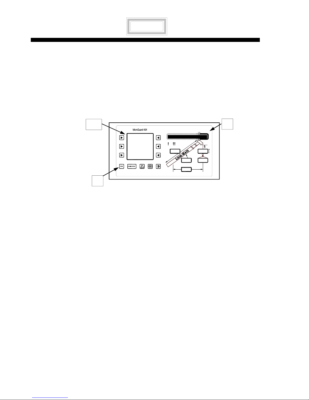
SYSTEM SELF-TEST
The Computer and Operator’s Display Console do a Self-Test when the power is turned on or
during operation when the ”TEST” button is pressed. The Self-Test verifies that the Computer,
Display Console, cables, and all remote sensors are working properly.
TEST SEQUENCE FOR DISPLAY CONSOLE:
1. Push TEST BUTTON (T). BLACK BAR GRAPH (B) spans entire window . All lights and all
7 SEGMENT DISPLAYS turn on and the ALARM sounds. Graphic Display (GD) reads:
“This is a Test.”
FIGURE 2.0
LIQUID
CRYSTAL
DISPLAYS
GD
B
2. If no Fault (problem) is found, the System will start displaying Load, Radius, Angle, etc.
3. Faults discovered during Self-Test will cause the red and yellow lights to turn on. The
Graphics Display (GD) will read: “OUT OF SERVICE.”
4. The Operator then presses and holds the TEST button causing the Fault to be identified
with a FAULT CODE NUMBER (See Section V) in the Graphics Display.
T
CAUSES FOR COMMUNICATION FAILURE:
A) Bad connections between the Display Console and the Computer.
B) Incorrect voltage from the Computer to the Display Console.
C) Failure of the serial Transmit/Receive IC in either the Computer, Display Console, or
Remote Bar Graph Unit.
D) Failure of the Reset IC in either the Computer or Display Console.
E) The Computer is locked up and not working.
F) The Display is locked up and not working.
MicroGuard® 434 System — Troubleshooting Manual PN W434800 Rev D 09/19/06
8
A
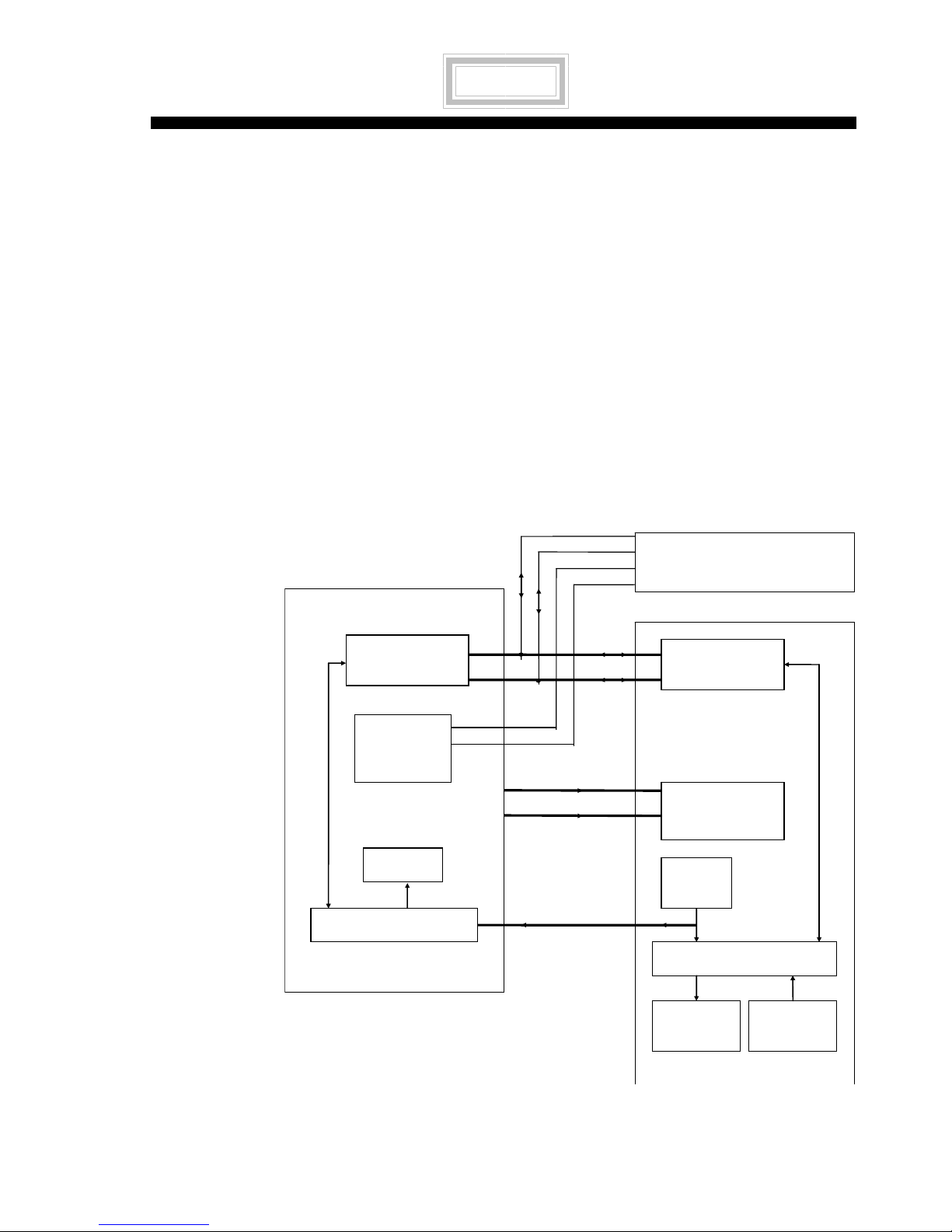
COMPUTER/DISPLAY COMMUNICATION
Communication problems are difficult to isolate because of the interaction between the Display
Console and the Computer. Failure of either unit causes malfunction of the Display Console. Such
problems need resolution before using the Problem Finding Tables.
Six wires, identified below and shown in the following diagram, connect the Computer to the
Display Console. (See Figure 4.8, page 40.)
DA Differential serial communication line
DB Differential serial communication line
RES Reset line from the display to the
computer
COMPUTER
TRANSCEIVER
IC6
5 VOLT
POWER
SUPPLY
+VP Power to Operator’s Display
Console
0V Common return
0V Common return
DA
DB
+5V
0V
D
DB
+VP
0V
REMOTE BAR GRAPH
DISPLAY CONSOLE
TRANSCEIVER
IC5
5 VOLT
REGULATOR
FIGURE 2.1
COMMUNICATION
BLOCK DIAGRAM
MicroGuard® 434 System — Troubleshooting Manual PN W434800 Rev D 09/19/06
RELAYS
CPU
“TEST”
Button
RESET
CPU
DISPLAYS BUTTONS
9
COMPUTER/DISPLAY COMMUNICATION CONTINUED
NORMAL OCCURRENCES
WHEN SYSTEM IS TURNED ON
OR
WHEN “TEST” BUTTON IS PUSHED.
OPERATOR’S DISPLAY
COMPUTER REMOTE BAR GRAPH
CONSOLE
READS:
”This is a SELF-TEST.”
After Self-Test, the relays
turn on and allow crane
motions.
All lights turn on during Self-Test
and then return to normal.
Lamps on during Self-Test.
Audio alarm sounds during
Self-Test.
Bar Graph spans full window.
TEST button resets both
Listen for the relay “Click.”
Computer and Display
Console.
The following tables describe the reactions of the Operator’s Display Console, Computer, and
Remote Bar Graph when 1 of the 6 wires has a simulated failure. The wires were disconnected one
at a time and the results recorded. These tables are intended to help identify a faulty wire or circuit.
EITHER DA OR DB IS OPEN TO THE DISPLAY
OPERATOR’S DISPLAY
CONSOLE
Shows everything remaining
after Self-Test.
Lamps remain on. Relays click with every reset.
Audio alarm remains OFF.
TEST button resets both the
Computer and the Display.
MicroGuard® 434 System — Troubleshooting Manual PN W434800 Rev D 09/19/06
10
COMPUTER REMOTE BA R GRAPH
Resets every 5 seconds. All lights on.
TEST button clicks the
relays.
COMPUTER/DISPLAY COMMUNICATION CONTINUED
DA AND DB ARE OPEN TO THE DISPLAY
OPERATOR’S
COMPUTER REMOTE BAR GRAPH
DISPLAY CONSOLE
Graphics Display
Reset repeats every 5 seconds. All lights on.
READS:
“Serial comms. Failure”
Lamps are on. Relays click with every reset.
Audio alarm on.
TEST button resets both
Computer & Display in
TEST button clicks the relays. Resets when the TEST button is
pressed.
about 14 seconds.
Wires DA and DB going to the Display unit can be checked with an Ohm meter. Unplug Connector
7 at the Computer and connect a meter to pins A and E on the cable. It should read between 210
and 230 ohms.
RESET IS OPEN TO THE COMPUTER
OPERATOR’S
COMPUTER REMOTE BAR GRAPH
DISPLAY CONSOLE
Operator’s Display
Console is normal
after Self-Test.
Graphics Display
remains blank when
TEST button is pushed.
The reset line comes from the Display Console and connects to the Computer through Connector
7, Pin D, and then connects to TB6-14 RES on the Termination Board.
pushed this line goes Hi (about 4.5v) and resets the computer. In normal operation the reset line is
Low (about 0v).
MicroGuard® 434 System — Troubleshooting Manual PN W434800 Rev D 09/19/06
Relays turn on and allow crane
motions.
Relay clicks
when TEST button is pushed.
Normal.
Resets
when TEST button is pushed.
When the “TEST” button is
11
COMPUTER/DISPLAY COMMUNICATION CONTINUED
+VP (RED WIRE) IS OPEN
DISPLAY COMPUTER REMOTE BAR
GRAPH
Entire Operator’s Display Console
does not respond.
Relay clicks when TEST button is
Relays turn on and allow crane
motions.
pushed.
Normal.
MicroGuard® 434 System — Troubleshooting Manual PN W434800 Rev D 09/19/06
12

DISPLAY OF FAULT CODES
When the System detects a problem, it is identified in the System as a Fault and given a Fault
Code Number. At the same time a warning is activated. Fault Codes are displayed by holding
down the TEST button. See SECTION V for a complete description of FAULTS.
If a warning sounds or is exhibited on the Operator’s Display Console, and a FAULT does not
register, check the OPERATOR’S SETTABLE ALARMS button.
MicroGuard® 434 System — Troubleshooting Manual PN W434800 Rev D 09/19/06
13
CRANE MOTIONS ARE DISABLED
Problem: Unable to boom down, extend boom, or hoist up.
Reason: The crane Motion Cut Solenoids aren’t powered.
Theory: The MicroGuard
and Motion Cut Solenoids of the crane. Refer to the MicroGuard
back cover of this Manual. Relay 1 cuts power when a Load Limit has been exceeded or a System
failure has been detected. Relay 2 cuts power when the Anti-two Block limit switch is opened.
ACTION RESULT DETAILED INFORMATION
®
434 System protection circuit has 2 relays, in series, between the Battery
®
434 System Diagram on the inside
Press and release the
TEST button on the
Press and Hold the TEST
button.
Press and Hold the
ALARM “OVERRIDE”
button for 5 seconds.
Measure the DC voltages
on Terminal Block 7 on the
Termination Board.
Measure the resistance
from Terminal Block 7 to
The System will perform a
Self-Test.
Fault codes will be
displayed until the button is
Relay 1 and Relay 2 will be
forced on by the computer
to provide power to the
Motion Cut Solenoids.
TB7-7 = 13.8V ( battery in )
TB7-8 = 13.8V ( jumper )
TB7-10 = 13.8V ( jumper )
TB7-7 to C8-B => 5 Ohms
TB7-11 to C8-E => 5 Ohms
Please refer to page 8.
Please refer to Fault Codes,
pages 66-72.
See the System Diagram the inside
back cover of this Manual to see the
voltage path from the battery through
the relays to the solenoids.
See the System Diagram on the inside
back cover of this Manual and the
Termination Board layout in Figure
4.24, page 63).
See Figure 4.21, page 60.
Check the wiring from the
computer to the Motion
Cable 8 supplies 13.8v to
the Motion Cut Solenoids.
Check the ATB Board
connections.
MicroGuard® 434 System — Troubleshooting Manual PN W434800 Rev D 09/19/06
14
All wires are making
contact.
See Figure 4.21, page 60.
ANTI-TWO-BLOCK CIRCUIT
The ANTI-TWO BLOCK switch is normally closed connecting ATBIN input to 0 volts. The
ANTI-TWO BLOCK WEIGHT holds the switch in this position. The switch is opened when the
weight is lifted. The ATBIN input has a 1 megohm pull up resistor that goes Hi when the switch
opens. The ATB board opens Relay 2 disabling crane motions. The ATB board also send s a signal
to the computer through DIN 13 allowing the computer to display an ATB alarm on the Operator’s
Display Console.
The ANTI-TWO BLOCK limit switch connects to the computer through a coax cable, slip rings
inside the Reeling Drum Assembly, and through cable 3. Please refer to EXTENSION REEL,
Section IV.
PROBLEM
There is an ATB ALARM
but there isn’t a TWO-
BLOCK condition on the
crane.
There is an ATB ALARM
but there isn’t a TWO
BLOCK problem on the
crane.
There is NO ATB ALARM
when the weight is lifted.
CRANE MOTION
REASON
DISABLED
The ANTI-TWO BLOCK circuit is open. Check
the connectors, cables, and slip rings for
continuity. The slip rings are inside the
Extension Reel. Check the position of the
“Selection Switch” mounted on the Anti-Two
Block Switch. It can be set at Main, Both, or
Jib and should be set to reflect the
configuration
of the crane.
CRANE MOTION OK The ATB board is not holding DIN 13 Hi.
Check the wire from the ATB board to the
Termination Board.
CRANE MOTION OK The ANTI-TWO BLOCK circuit is shorted to
ground. Unplug cable 3 to disconnect the ATB
switch. This generates an ATB ALARM. With
an Ohm meter, measure pins B and G of the
cable and lift the ATB WEIGHT. The
resistance is low during normal operation
and should switch to OPEN when the weight
is lifted.
MicroGuard® 434 System — Troubleshooting Manual PN W434800 Rev D 09/19/06
15

SWING POT SENSOR
FAULT CODE AAA 096
The Swing Pot Sensor is a 2.5k pot with two wiper arms separated at 90°. The System Diagram
on the inside back cover of this Manual shows the Swing Pot.
The Swing Pot can be checked with an Ohm meter. Disconnect cable 6 and measure from pin “C”
to “D” = 2.5k ± 20%.
Measure the wiper arms from pin “B” to “E” = 1.88k ± 20%.
If power going to the Swing Pot is cut, or if either wiper arm opens, the System will report a Fault.
Refer to Section IV, SWING SENSOR, page 64.
MicroGuard® 434 System — Troubleshooting Manual PN W434800 Rev D 09/19/06
16
BOOM EXTENSION SENSOR
FAULT CODE AAA 004
The Boom Extension Sensor sends a voltage to the computer. The voltage is sent through cable 3
to AIN2 on the Termination Board. The voltage on AIN2 is about .2v when the boom is retracted
and increases about .125v per drum revolution. If the voltage is missing or out of range, the
System will send forth an alarm. The Boom Extension Sensor is located inside the
Boom Extension Box.
PROBLEM ACTION RESULT
INDICATOR OUT OF
SERVICE Alarm.
AIN2 is not getting voltage
or is out of range.
Press and hold the TEST
button.
Measure AIN2 on the
Termination Board.
Fault Code AAA 004.
Retracted = ABOUT .2v.
The voltage increases as
the boom is extended.
The Extension Sensor is
not getting 5.25v from the
computer.
Measure the 5.25v on the
terminal strip inside the
Extension Reel. Check
.
cable 3.
NOTE: The computer may need to be re-calibrated when the Extension Sensor is replaced
or adjusted.
Please refer to the MicroGuard
®
434 System Diagram on the inside back cover of this manual. Also
review Section IV in this Manual for a detailed discussion of the Extension Sensor.
MicroGuard® 434 System — Troubleshooting Manual PN W434800 Rev D 09/19/06
17
BOOM ANGLE SENSOR
FAULT CODE AAA 008
The Boom Angle Sensor sends a voltage to the computer. The voltage is sent through cable 3 to
AIN 3 on the Termination Board. The voltage on AIN3 is about .437v when the Boom is at 0° and
4.375v at 90°. If the voltage is missing or out of this range, the System will display a Fault. The
Angle Sensor is located inside the Boom Extension box.
PROBLEM ACTION RESULT
System Overload
Alarm.
AIN3 is not getting
voltage or is out of
range.
Press and hold the
TEST button.
Measure AIN3 on the
Termination Board.
Fault Code AAA 008
Boom angle 0° = .437v
Boom angle 30° = 1.750v
Boom angle 60° = 3.062v
Boom angle 90° = 4.375v
The Angle Sensor is
not getting 5.25v from
the computer.
Measure the 5.25v on
the terminal strip
inside the Extension
Reel. Check cable 3.
NOTE: The computer may need to be re-calibrated when the angle sensor is replaced or adjusted.
FOR A MORE DETAILED DESCRIPTION, SEE SECTION IV, PAGE 53.
MicroGuard® 434 System — Troubleshooting Manual PN W434800 Rev D 09/19/06
18
PRESSURE TRANSDUCERS
FAULT CODE AAA 001 OR 002
The Rod/Piston Pressure Transducers turn hydraulic pressure into voltages that can be used by the
computer. Each transducer has its own cable. They plug into connectors 1 and 2. Connector 1 goes
to Terminal Block 2, pins 1, 2, 3, + 4 and connector 2 uses pins 6, 7, 8, + 9 on the
Termination Board.
CONNECTOR 1 IS THE TXO CHANNEL ON THE INTERFACE BOARD
PROBLEM ACTION RESULTS
INDICATOR OUT OF
SERVICE Alarm.
Power from the computer to the
transducer is missing.
Input TXO + or - is missing or
incorrect.
The transducer or cable has
failed.
Connector to Terminal block
open.
Press and hold the TEST
button.
Measures the +5.25v supply
on the Termination Board.
Measures TXO inputs on the
Termination Board.
Unplug the cable and
measure the resistance.
Measure the connections
from terminal block 2 to
connector 1.
Fault Code AAA
001
Terminal block 2
Pin 1 (+DR) +5.25v
Terminal block 2
PIN 3 (TXO+) +2.625v
PIN 4 (TXO–) +2.625v
Pin C to D = 340 to 360 Ohm
Pin B to E = 340 to 360 Ohm
Pin B, C, D, & E open to the
shield.
Pin C to TB2 +DR = > 1 Ohm
Pin D to TB2 –DR = > 1 Ohm
Pin B to TB2 TXØ+ = > 1 Ohm
NOTE: The System will need to be re-calibrated if a new sensor is installed.
FOR A MORE DETAILED DESCRIPTION, SEE PRESSURE SENSOR SEC. IV, PAGE 54.
MicroGuard® 434 System — Troubleshooting Manual PN W434800 Rev D 09/19/06
Pin E to TB2 TXØ– = > 1 Ohm
19
PRESSURE TRANSDUCERS CONTINUED
CONNECTOR 2 IS THE TX1 CHANNEL ON THE INTERFACE BOARD
PROBLEM ACTION RESULTS
INDICATOR OUT OF
SERVICE Alarm.
Power from the computer to
the transducer is missing.
Input TX1 + or - is missing or
incorrect.
The transducer or cable has
failed.
Press and hold the TEST
button.
Measures the +5.25v
supply on the Termination
Board.
Measures TX1 inputs on
the interface board.
Unplug the cable and
measure the resistance.
Fault Code AAA
002
Terminal block 2
Pin 6 (+DR) +5.25v
Pin 7 (-DR) 0 volts
Terminal block 2
PIN 8 (TX1+) +2.625v
PIN 9 (TX1-) +2.625v
Pin C to D = 340 to 360 Ohm
Pin B to E = 340 to 360 Ohm
Pin B, C, D, & E open to the
shield.
Connector to Terminal block
open.
NOTE: The System will need to be re-calibrated if a new sensor is installed.
MicroGuard® 434 System — Troubleshooting Manual PN W434800 Rev D 09/19/06
20
Measure the connections
from terminal block 2 to
connector 2.
Pin C to TB2 +DR = > 1 Ohm
Pin D to TB2 –DR = > 1 Ohm
Pin B to TB2 TX1+ = > 1
Ohm
Pin E to TB2 TX1– = > 1 Ohm
REMOTE BAR GRAPH
The Remote Bar Graph is connected to the computer with 4 wires.
DA Serial Communication Line
DB Serial Communication Line
+5v Power
Ground Power Return
PROBLEM ACTION RESULT
No lights.
(Not getting power.)
All lights remain on after
Self-Test. (No serial
communication.)
Lights pulsating.
(DA or DB is missing.)
Loose connection inside
the computer from
connector -5 to
terminal block 6.
Unplug cable 5. Measure
the 5 volt on connector 5 of
the computer.
Unplug cable 5 and
measure the resistance
from Pin D to Pin E on the
cable connector.
Unplug cable 5 and
measure the resistance
from Pin D to Pin E on the
cable connector.
Measure the resistance
from connector 5 to
terminal block 6 inside the
computer.
Pin A = + 5 volts.
Pin C = 0 volts
Pin D to E measures
between 210 and 230
ohms. If not, the cable is
open or shorted.
Pin D to E measures
between 210 and 230
ohms. If not, the cable is
open.
Pin C to TB9=>1 ohm
Pin A to TB10=>1 ohm
Pin D to TB12=>1 ohm
Pin E to TB13=>1 ohm
NOTE: The Remote Bar Graph unit must always be returned to the Service Center
for repair. Call your Service Representative.
SEE COMPUTER/DISPLAY COMMUNICATION BLOCK DIAGRAM PAGE 9
MicroGuard® 434 System — Troubleshooting Manual PN W434800 Rev D 09/19/06
AND REMOTE BAR GRAPH, PAGE 43.
21

THIS PAGE SHOULD BE BLANK.
MicroGuard® 434 System — Troubleshooting Manual PN W434800 Rev D 09/19/06
22

Section III
SYSTEM INSTALLATIONS....................................................................................23
SELECTING THE RIGHT SYSTEM INSTALLATION ILLUSTRATION.....................24
SYSTEM LAYOUTS WITH CORRESPONDING SERIAL NUMBER PREFIX..........25
1. SYSTEM INSTALLATION E1.......................................................................................25
2. SYSTEM INSTALLATION D3, E9, F1, F2, & F3...........................................................26
MicroGuard® 434 System — Troubleshooting Manual PN W434800 Rev D 09/19/06
23
 Loading...