

GREER Company MICROGUARD 424 Calibration Manual
GREER
GREER COMPANY
GREERGREER
COMPANY
COMPANYCOMPANY
MODELS USING M414371A & M414380C PROGRAMS
MODELS USING M414371A & M414380C PROGRAMS
MODELS USING M414371A & M414380C PROGRAMSMODELS USING M414371A & M414380C PROGRAMS
MicroGuard 424
TEST
W
MAX
5.82
3.46
ATB ALARM
Crane Systems
MICROGUARD
MICROGUARD
MICROGUARDMICROGUARD
for
GENERIC
GENERIC
GENERICGENERIC
57.2
100%
O/R FULEXT 360
CRANE
SET UP
60%
8
STOWED
DEDUCT
DEDUCT
ERECTED STOWED
424
F 49.1
WORKING
o
AREA
W
INFORMATION
Lifting point
MAIN BOOM
VIEW
OPERATOR ALARMS
GREER COMPANY 1918 EAST GLENWOOD PLACE SANTA ANA, CALIFORNIA 92705 TEL: 714)259-9702 FAX: 259-9702
MicroGuard 424 GENERIC Calibration Procedure for Programs M414371A & M414380C PN W424104- 11/23/99
SET
DOWNCLEAR UP
CONTRAST
SELECT
CALIBRATION PROCEDURE
CALIBRATION PROCEDURE
CALIBRATION PROCEDURECALIBRATION PROCEDURE
1 of 44

GREER COMPANY
GREER COMPANY
GREER COMPANYGREER COMPANY
Crane Systems
424 SYSTEM
MicroGuard
MicroGuard
MicroGuardMicroGuard
GENERIC CALIBRATION MANUAL
TABLE OF CONTENTS
TABLE OF CONTENTS
TABLE OF CONTENTSTABLE OF CONTENTS
GENERAL INFORMATION .................................................................................................................................... 3
CALIBRATION PROCEDURES ............................................................................................................................. 4
COMMAND 00 RUN............................................................................................................................................5
COMMAND 01 PERSONALITY ..........................................................................................................................5
ENTRY TO CALIBRATION ROUTINES ................................................................................................................6
COMMAND 01/2 INITIALIZE..................................................................................................................................6
COMMAND 01/0 SAVE..........................................................................................................................................7
COMMAND 02 TEST/FAULT..............................................................................................................................7
FAULT CODES................................................................................................................................................8
NUMBER ENTRY .......................................................................................................................................9-10
COMMAND 03 ZERO.................................................................................................................................11
424 SYSTEM
424 SYSTEM424 SYSTEM
ZERO PRESSURE TRANSDUCERS ................................................................................................11-12
ZERO EXTENSION SENSOR ................................................................................................................13
ZERO BOOM ANGLE SENSOR ............................................................................................................. 14
COMMAND 04 SPAN........................................................................................................................................15
BOOM ANGLE SENSOR ..............................................................................................................................15
EXTENSION SENSOR.................................................................................................................................. 16
COMMAND 05 SWING ................................................................................................................................17-18
CONFIGURATION SELECTION.....................................................................................................................19-20
COMMAND 06 PRESSURE..............................................................................................................................21
COMMAND 07 RADIUS/MOMENT MAIN BOOM (MODE A) ......................................................................22-24
COMMAND 07 RADIUS/MOMENT MANUAL (MODE B) ............................................................................25-27
COMMAND 08 BOOM DEFLECTION CORRECTION .....................................................................................28
COMMAND 09 ANNULAR GAIN ......................................................................................................................29
COMMAND 12 WINCHES ................................................................................................................................30
COMMAND 13 ATTACHMENTS ......................................................................................................................30
COMMAND 15 ALARM LIMITS ...................................................................................................................31-33
COMMAND 16 ROPE DATA.............................................................................................................................34
COMMAND 17 AMPLIFIER GAIN.....................................................................................................................35
COMMAND 01/0,3, 4 SAVE/BACKUP/RESTORE.........................................................................................36-37
COMMAND 19 DIGITAL INPUTS .....................................................................................................................38
GLOSSARY.....................................................................................................................................................39-44
GREER COMPANY 1918 EAST GLENWOOD PLACE SANTA ANA, CALIFORNIA 92705 TEL: 714)259-9702 FAX: 259-9702
MicroGuard 424 GENERIC Calibration Procedure for Programs M414371A & M414380C PN W424104- 11/23/99
2 of 44
GREER COMPANY
A
GREER COMPANY
GREER COMPANYGREER COMPANY
Crane Systems
GENERAL INFORMATION
GENERAL INFORMATION
GENERAL INFORMATIONGENERAL INFORMATION
After satisfactory installation of the complete system, ensure that it is correctly wired in accordance with the Wiring
Diagram, which is issued with the duty chip.
Before carrying out any crane operations ensure that the crane is on firm and level ground and that the outrigger
beams are fully extended and jacks are correctly extended to level the carrier.
CAUTION: Do not exceed any
MicroGuard
TEST
W
MAX
W
VIEW SET CLEAR DOWN UP
414
100%
INFORMATION
CONTRASTOPERATOR ALARMS
CRANE
SET UP
STOWED
DEDUCT
ERECTED STOWED
SELECT
WORKING
AREADEDUCT
structural or stability limits
throughout this procedure.
For cranes using executive
programs labeled
M414370,M414371 or
M414380: Attachments can
remain on as long as they are
correctly selected in the
computer.
For cranes using other
programs:
Remove all
attachments which can be
optionally stowed or erected on
the boom during normal
operation (e.g. aux.head flys or
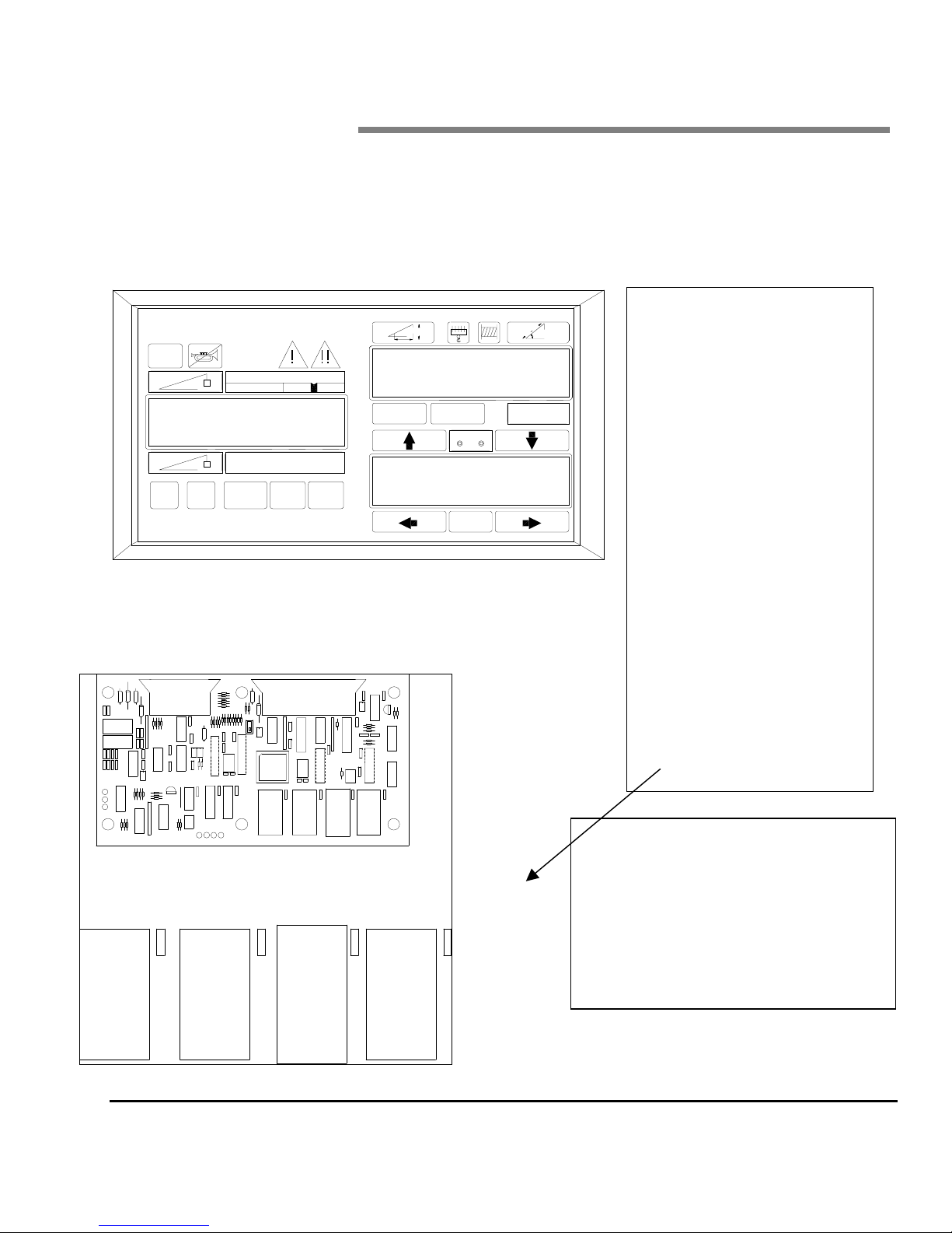
jibs The computer must be fitted
with the appropriate program
and duty chips. They are found
on the main computer board as
shown below.
PROGRAM
CHIP
DUTY
CHIP
IC2 IC3 IC7
GREER COMPANY 1918 EAST GLENWOOD PLACE SANTA ANA, CALIFORNIA 92705 TEL: 714)259-9702 FAX: 259-9702
MicroGuard 424 GENERIC Calibration Procedure for Programs M414371A & M414380C PN W424104- 11/23/99
PERSONALITY
CHIP
3 of 44
WARNING: WHEN THE SYSTEM IS IN
THE CALIBRATION MODE, THE AUDIBLE
ALARM AND FUNCTION KICK-OUTS ARE
INHIBITED AND THERE IS NO
PROTECTION FROM TWO-BLOCK OR
OVERLOAD. ALL CRANE OPERATIONS
RE AT THE SOLE DISCRETION OF THE
OPERATOR.
GREER COMPANY
GREER COMPANY
GREER COMPANYGREER COMPANY
Crane Systems
CALIBRATION PROCEDURES
CALIBRATION PROCEDURES
CALIBRATION PROCEDURESCALIBRATION PROCEDURES
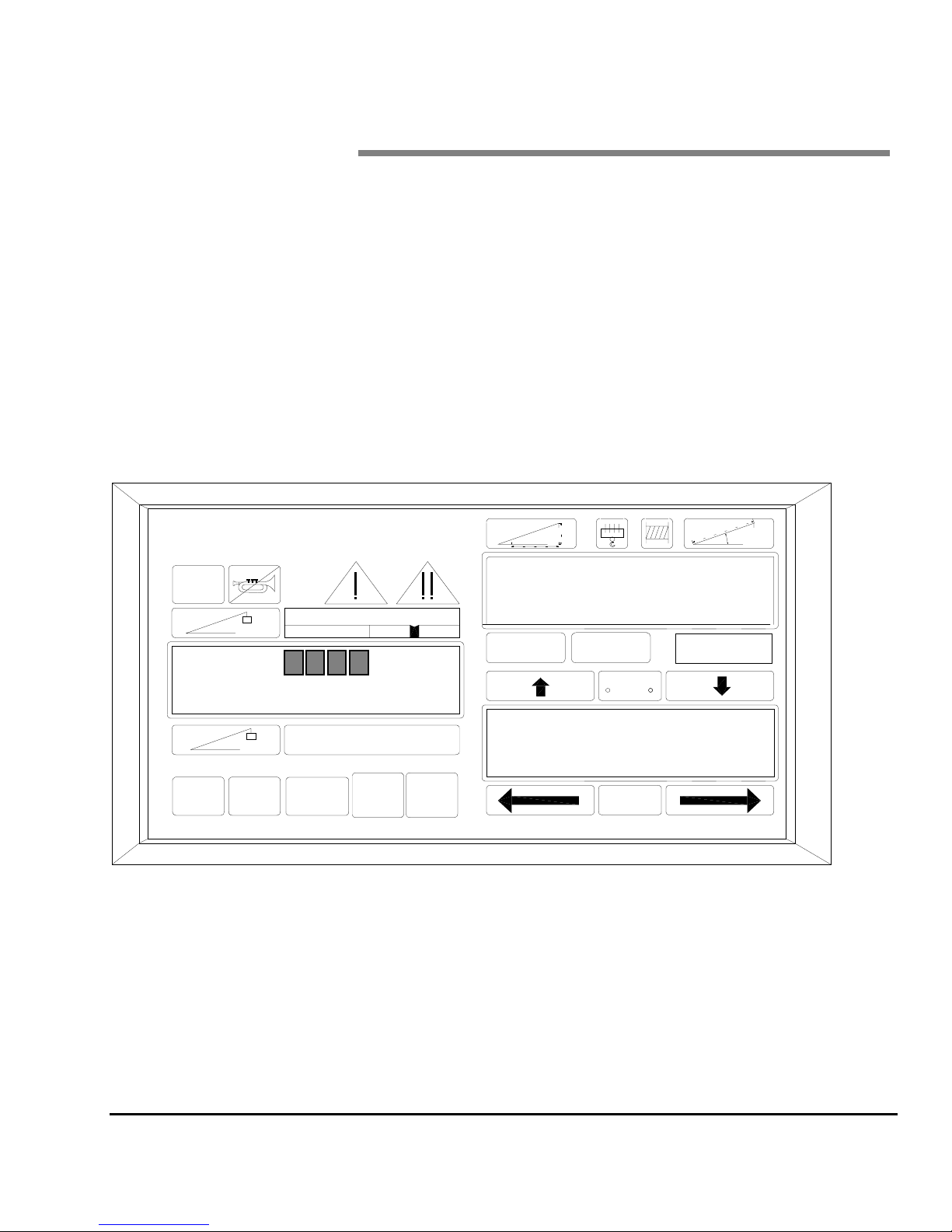
The Display Unit provides the interface between the user and the calibration program. By pressing the various
keypads on the Display, the user communicates with the program and executes the calibration. Information and
data stored in the Display Unit are activated via on-screen prompts.
The six keypads are shown below with a description of their basic function.
Calibration routines are initiated by simultaneously pressing and holding the
approximately 2 seconds. The display will then request entry of the Calibration Security Code.
To enter the Calibration Security Code, press the following keys IN THE SEQUENCE SHOWN BELOW.
If the wrong sequence is used or if the entry is not completed within 5 seconds, the calibration entry will be aborted
and must be restarted.
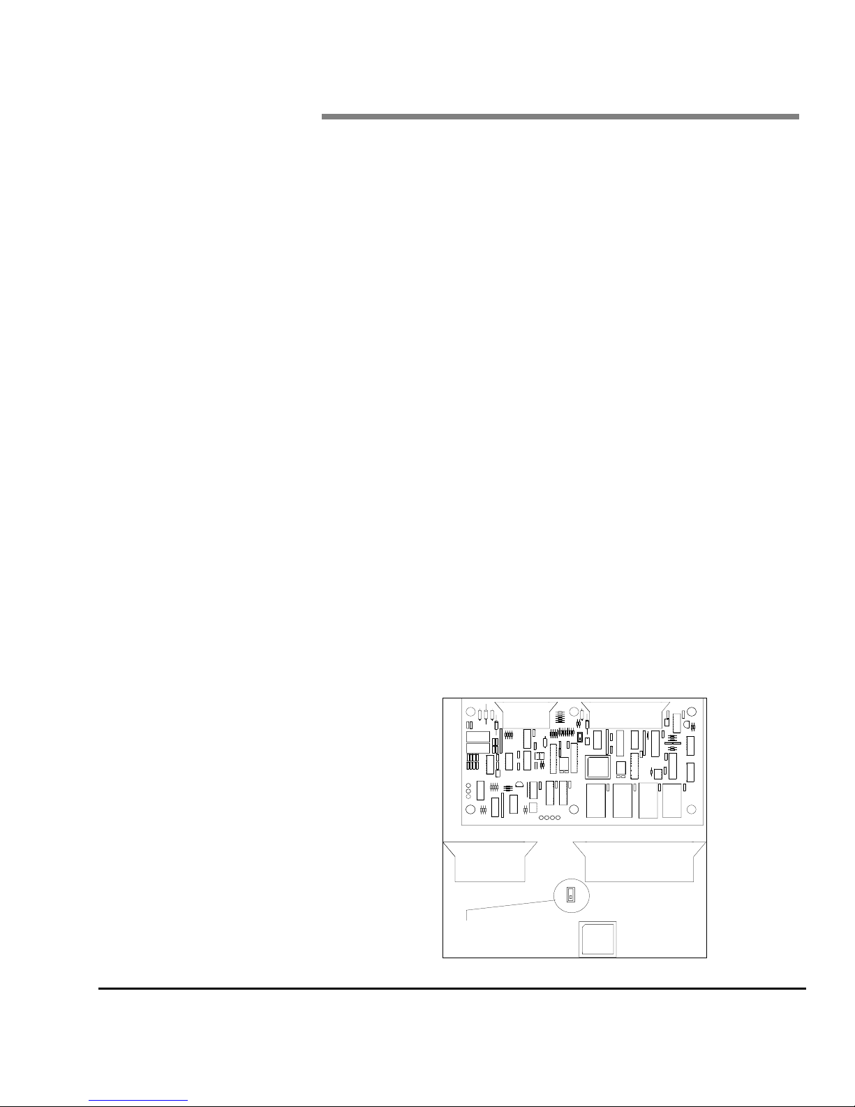
Calibration procedures will only work with the
CAL switch in the computer set to the CAL
position. To gain access to the CAL switch it is
necessary to remove the cover from the
computer assembly. The switch is located near
the center of the computer board between and
below the ribbon cable connectors.
UP ARROW INCREASES A NUMBER
××××
ØØØØ
ÕÕÕÕ
DOWN ARROW DECREASES A NUMBER
LEFT ARROW CHANGES A CATEGORY OR SENSOR
ÖÖÖÖ RIGHT ARROW CHANGES A CATEGORY AND/OR EXITS
SELECT
TEST
SELECT KEY SELECTS AND CALIBRATE
TEST KEY STARTS THE CALIBRATION
and
TEST
×××× ØØØØ ÕÕÕÕ ÖÖÖÖ
SELECT
SELECT
keys for
GREER COMPANY 1918 EAST GLENWOOD PLACE SANTA ANA, CALIFORNIA 92705 TEL: 714)259-9702 FAX: 259-9702
MicroGuard 424 GENERIC Calibration Procedure for Programs M414371A & M414380C PN W424104- 11/23/99
CAL SWITCH
4 of 44

GREER COMPANY
GREER COMPANY
GREER COMPANYGREER COMPANY
Crane Systems
COMMAND 00 RUN
COMMAND 00 RUN
COMMAND 00 RUNCOMMAND 00 RUN
Following correct entry of the calibration code, the System will be in the MONITOR mode and will be at
Command 00 Run. Execution of this Command will cause the System to carry out a System Self-TEST followed
by a return to the working screen.
COMMAND 01 PERSONALITY
COMMAND 01 PERSONALITY
COMMAND 01 PERSONALITYCOMMAND 01 PERSONALITY
Command 01 Personality is used to manipulate the crane calibration data.
The System has storage space for two sets of data in the EEPROM IC7.
used by the main program. Back-up Personality is used to keep a protected copy of the calibration data.
For convenience the sets of personality data are called:
"A" = the Active Personality in IC7
"B".= the Backup Personality in IC7
Command 01 provides the following functions:
Displays the status of the personality sets.
♦
Moves data between the two sets
♦
Deletes data from the active personality.
♦
Copies data to a back-up chip
♦
Retrieves data from a back-up chip.
♦
When Command 01 is first selected and after copying data, both "A" and "B" sets are checked for correct
check-sum. This is indicated by "good" or "bad" beside the respective reference in the lower display. Set "A" is
also checked against set "B". If the data is identical, this is indicated by "same;" if not the same, by "diff." Moving
data is by accomplished by means of the sub-commands selected and a special [CAL] sequence. This requires
the entry of a Code that is the same as the one used to enter the calibration routines and provides adequate
opportunity to abort the procedure. This is necessary because some of the sub-commands cause previously
entered data to be irretrievably lost.
Active Personality
is the data actually
SUB-COMMAND 0 SAVE Saves "A" into "B". (B data is lost)
SUB-COMMAND 1 XCHG Exchanges "A" with "B" (data is not lost)
SUB-COMMAND 2 INIT Initializes "A" prior to new calibration (A data is lost).
SUB-COMMAND 3 BACK Copies the active calibration to a back-up chip (data is not lost).
SUB-COMMAND 4 RETR Retrieves the calibration from a back-up chip.
WARNING
POWER TO THE SYSTEM SHOULD BE SWITCHED OFF BEFORE INSERTING OR REMOVING ANY
INTEGRATED CIRCUITS. FAILURE TO OBSERVE THIS PRECAUTION MAY CAUSE PERMANENT DAMAGE
TO THE SYSTEM OR ITS COMPONENTS AND RESULT IN THE LOSS OF CALIBRATION DATA.
GREER COMPANY 1918 EAST GLENWOOD PLACE SANTA ANA, CALIFORNIA 92705 TEL: 714)259-9702 FAX: 259-9702
MicroGuard 424 GENERIC Calibration Procedure for Programs M414371A & M414380C PN W424104- 11/23/99
5 of 44

GREER COMPANY
GREER COMPANY
GREER COMPANYGREER COMPANY
Crane Systems
WARNING
If the System has been previously calibrated and the intention is only to access data or change only a portion of
the previous calibration,DO NOT perform the initialization process that follows or the entire previous calibration
data will be lost.
ENTRY TO CALIBRATION ROUTINES
ENTRY TO CALIBRATION ROUTINES
ENTRY TO CALIBRATION ROUTINESENTRY TO CALIBRATION ROUTINES
OR
OR
AND
ØØØØ
ØØØØ
TEST
START THE ROUTINE BY PRESSING AND
HOLDING FOR APPROXIMATELY 2 SECONDS
FOLLOW THE CAL ENTRY SEQUENCE
CONFIRM THE CALIBRATION (or abort with Ö)
If the wrong sequence is used or if the entry is not completed within 5 seconds, the calibration entry will be aborted
and must be restarted. Before the first calibration of a new system, prepare the Personality Memory by following
the sequence below.
CAUTION
CAUTION
CAUTIONCAUTION
THIS PROCEDURE TRANSFERS PRE-CALIBRATED DATA TO THE PERSONALITY CHIP. IF THIS HAS ALREADY BEEN
CARRIED OUT AND THE INTENTION IS TO ONLY PARTIALLY CALIBRATE OR TO MODIFY CALIBRATION OR DATA IN
AN ALREADY CALIBRATED SYSTEM,
CALIBRATION.
COMMAND 01/2 INITIALIZE
COMMAND 01/2 INITIALIZE
COMMAND 01/2 INITIALIZECOMMAND 01/2 INITIALIZE
SCROLL TO 01 PERSONALITY BY PRESSING
START THE COMMAND BY PRESSING
SCROLL TO 01/2 INITIALIZE BY PRESSING
DO NOT
CARRY OUT THE INITIALIZE ROUTINE. PROCEED DIRECTLY WITH THE
SELECT
×××× ØØØØ ÕÕÕÕ ÖÖÖÖ
SELECT
××××
SELECT
××××
START THE COMMAND BY PRESSING
FOLLOW THE CAL ENTRY SEQUENCE
CONTINUE THE INITIALIZATION BY PRESSING
CONFIRM THE CALIBRATION (or abort with Ö)
SEE NOTE
AFTER THE MESSAGE CALIBRATING, EXIT BY
PRESSING
NOTE: The System will return to the MONITOR MODE but will remain in the CALIBRATION ROUTINE.
This procedure completely erases all previous data from the A personality. There is an opportunity to ABORT the
procedure at this point by first pressing
GREER COMPANY 1918 EAST GLENWOOD PLACE SANTA ANA, CALIFORNIA 92705 TEL: 714)259-9702 FAX: 259-9702
MicroGuard 424 GENERIC Calibration Procedure for Programs M414371A & M414380C PN W424104- 11/23/99
SELECT
×××× ØØØØ ÕÕÕÕ ÖÖÖÖ
SELECT
SELECT
ÖÖÖÖ
. Follow by pressing SELECT to erase the memory.
ÖÖÖÖ
6 of 44

GREER COMPANY
GREER COMPANY
GREER COMPANYGREER COMPANY
Crane Systems
COMMAND 01/0 SAVE
COMMAND 01/0 SAVE
COMMAND 01/0 SAVECOMMAND 01/0 SAVE
Upon completion of a calibration, it is necessary to carry out Command 01/0 SAVE. Refer to at the end of this
manual. There is no reason, however, why this command should not be used at any time during the intermediate
stages of a calibration, for example at the end of a period of work or if desired after each section of a calibration
has been completed. The use of this command will ensure that a copy of the calibration, up to the point of carrying
out "save", will be contained in the back-up memory.
SCROLL TO 01 PERSONALITY BY PRESSING
××××
OR
ØØØØ
START THE COMMAND BY PRESSING
SCROLL TO 01/0 SAVE BY PRESSING
SELECT
××××
START THE COMMAND BY PRESSING
FOLLOW THE CAL ENTRY SEQUENCE
SELECT
×××× ØØØØ ÕÕÕÕ ÖÖÖÖ
CONTINUE THE SAVE BY PRESSING SELECT
CONFIRM THE CALIBRATION (or abort with Ö)
SEE NOTE
AFTER THE MESSAGE "CALIBRATING," THE
DISPLAY WILL READ "A" GOOD "B" GOOD SAME
EXIT BY PRESSING
NOTE:
NOTE: This procedure completely erases all previous data from the B personality. There is an opportunity to
NOTE:NOTE:
ABORT
COMMAND 02 TEST/FAULT
COMMAND 02 TEST/FAULT
COMMAND 02 TEST/FAULTCOMMAND 02 TEST/FAULT
COMMAND 02 IS USED TO ACTIVATE A SYSTEM SELF-TEST WHICH WILL DETECT AND DISPLAY ANY ERRORS
PRESENT IN THE SYSTEM. THESE ERRORS ARE SHOWN BY MEANS OF AN ERROR CODE.
Carry out the Command using the following sequence:-
the procedure at this point by use of the right arrow
SCROLL TO 02 TEST/FAULT BY PRESSING
SELECT
ÖÖÖÖ
ÖÖÖÖ
××××
START THE COMMAND BY PRESSING
SELECT
ØØØØ
OR
Continuing with SELECT will erase the memory
ØØØØ
OR
THE SYSTEM WILL EXECUTE A SELF-TEST AND
DISPLAY FAULT CODES
EXIT FROM THE ROUTINE BY PRESSING
GREER COMPANY 1918 EAST GLENWOOD PLACE SANTA ANA, CALIFORNIA 92705 TEL: 714)259-9702 FAX: 259-9702
MicroGuard 424 GENERIC Calibration Procedure for Programs M414371A & M414380C PN W424104- 11/23/99
ÖÖÖÖ
7 of 44

GREER COMPANY
GREER COMPANY
GREER COMPANYGREER COMPANY
Crane Systems
FAULT CODES
FAULT CODES
FAULT CODESFAULT CODES
GROUP "A" ANALOG SENSORS
GROUP "A" ANALOG SENSORS
GROUP "A" ANALOG SENSORSGROUP "A" ANALOG SENSORS
CODE
AAA
000
001
002
004
008
016
032
064
GROUP "B" INPUTS AND OUTPUTS
GROUP "B" INPUTS AND OUTPUTS
GROUP "B" INPUTS AND OUTPUTSGROUP "B" INPUTS AND OUTPUTS
CODE
BB
00
01
02
04
GROUP "C" MEMORY
GROUP "C" MEMORY
GROUP "C" MEMORYGROUP "C" MEMORY
CODE
CC
00
01
02
04
08
GROUP "D" GENERAL
GROUP "D" GENERAL
GROUP "D" GENERALGROUP "D" GENERAL
CODE
DD
00
01
02
04
NO FAULTS
SENSOR 0 PISTON PRESSURE TRANSDUCER
SENSOR 1 ROD SIDE PRESSURE TRANSDUCER
SENSOR 2 EXTENSION SENSOR
SENSOR 3 BOOM ANGLE SENSOR
SENSOR 4 UPPERSTRUCTURE ANGLE SENSOR
SENSOR 5 SWING POTENTIOMETER "A"
SENSOR 6 SWING POTENTIOMETER "B"
NO FAULTS
FAULT 1 DIGITAL INPUT AND OUTPUT
FAULT 2 ANALOG INPUT AND OUTPUT
FAULT 4 DISPLAY UNIT
NO FAULTS
FAULT 1 EXECUTIVE ROM
FAULT 2 DUTY ROM
FAULT 4 SCRATCHPAD RAM
FAULT 8 PERSONALITY ROM
NO FAULTS
FAULT 1 NO DUTY FOUND
FAULT 2 CURRENT DUTY BAD
FAULT 4 CONFIGURATION NOT CALIBRATED
GREER COMPANY 1918 EAST GLENWOOD PLACE SANTA ANA, CALIFORNIA 92705 TEL: 714)259-9702 FAX: 259-9702
MicroGuard 424 GENERIC Calibration Procedure for Programs M414371A & M414380C PN W424104- 11/23/99
8 of 44

GREER COMPANY
GREER COMPANY
GREER COMPANYGREER COMPANY
Crane Systems
NUMBER ENTRY
NUMBER ENTRY
NUMBER ENTRYNUMBER ENTRY
The MicroGuard System does not have number entry keys. A special number entry procedure is used to allow
the simple entry of numbers. W hen numerical entry of data is required, the center display will change to allow the
entry of numbers. There are 5 categories in the display, as follows.
•
SELECTS A DECIMAL POINT
0
1. W
arrows pointing to the category.
• ÖÖÖÖ0ÕÕÕÕ ß C E
2. N
SELECT key. Successive numbers up to a total of five digits may be entered this way. If a number requires a
decimal point, the number is entered by moving the highlighted selection to the decimal point by means of
The decimal point then becomes highlighted.
ÖÖÖÖ
3. T
flashing cursor returns to the digits for the completion of the number entry. If a negative value is to be entered, the
number digit(s) must be entered first followed by the change sign command (enter the number and then move the
cursor to highlight the minus sign using
ß
C
E
hen the number entry is started, the display flashes on the number entry category that is highlighted by
umbers are changed using the
••••
ÕÕÕÕ 0
he decimal point is entered using the SELECT key. After the selection of a decimal point, the highlighted
SELECTS A DIGIT 0-9. THE
ARE USED TO CHANGE A NUMBER
CHANGE SIGN +/-
CLEARS A CURRENTLY DISPLAYED NUMBER
TERMINATES THE NUMBER AND COMPLETES
THE ENTRY PROCESS
and
××××
ß
C E
ÖÖÖÖ
keys. When selected, the required number is entered using the
ØØØØ
).
AND Ø KEYS
×
ÕÕÕÕ
.
ÕÕÕÕ C E
ÖÖÖÖ
ßßßß
.
•
0 ÖÖÖÖ
4. P
highlight the C using
•
5. P
correct number. After entry of all digits, decimal point and sign changes, move the cursor to E using
SELECT to terminate the sequence.
•
GREER COMPANY 1918 EAST GLENWOOD PLACE SANTA ANA, CALIFORNIA 92705 TEL: 714)259-9702 FAX: 259-9702
ress SELECT to change to a negative value. If an error is made in the entry of data, move the cursor to
0 ß ÖÖÖÖCÕÕÕÕ E
ress SELECT to delete the erroneous number, move the cursor back to the entry of digits and enter the
0 ß C ÖÖÖÖEÕÕÕÕ
MicroGuard 424 GENERIC Calibration Procedure for Programs M414371A & M414380C PN W424104- 11/23/99
9 of 44
and press
ÖÖÖÖ

GREER COMPANY
GREER COMPANY
GREER COMPANYGREER COMPANY
Crane Systems
NUMBER ENTRY
NUMBER ENTRY
NUMBER ENTRYNUMBER ENTRY
IN THE EXAMPLE THAT FOLLOWS, AN ARBITRARY NUMBER OF MINUS 123.45 HAS BEEN CHOSEN TO
ILLUSTRATE THE USE OF THE PROCEDURE.
SELECT THE FIRST DIGIT
BY PRESSING
WHEN AT
SELECT THE SECOND DIGIT
BY PRESSING
WHEN AT
SELECT THE THIRD DIGIT
BY PRESSING
WHEN AT
MOVE THE CURSOR TO THE DECIMAL
POINT
ENTER THE DECIMAL POINT BY
PRESSING
SELECT THE FIRST DECIMAL PLACE
Ö4Õ
WHEN AT
SELECT THE NEXT DECIMAL PLACE
BY PRESSING
Ö1Õ
Ö2Õ
Ö3Õ
BY PRESSING
ÖÕ
Ö4Õ
Õ
BY PRESSING
WHEN AT
MOVE THE CURSOR TO THE CHANGE
SIGN
ÖÖÖÖ
SELECT THE MINUS SIGN BY PRESSING
Ö5Õ
BY PRESSING
ÕÕÕÕ
ßßßß
(continued)
Ö1Õ
PRESS
Ö2Õ
PRESS
Ö3Õ
PRESS
PRESS
PRESS
Ö5
××××
OR
SELECT
××××
OR
SELECT
××××
OR
SELECT
ÕÕÕÕ
SELECT
××××
OR
SELECT
××××
OR
SELECT
ÖÖÖÖ
SELECT
ØØØØ
ØØØØ
ØØØØ
ØØØØ
ØØØØ
MOVE THE CURSOR TO
PRESSING ...............................SEE NOTE
TERMINATE THE ENTRY BY PRESSING
NOTE
AFTER THE ENTRY OF FIVE DIGITS, THE CURSOR WILL MOVE AUTOMATICALLY TO
IF LESS THAN FIVE DIGITS HAVE BEEN ENTERED, USE
GREER COMPANY 1918 EAST GLENWOOD PLACE SANTA ANA, CALIFORNIA 92705 TEL: 714)259-9702 FAX: 259-9702
MicroGuard 424 GENERIC Calibration Procedure for Programs M414371A & M414380C PN W424104- 11/23/99
ÖÖÖÖEÕÕÕÕ
BY
ÖÖÖÖ
SELECT
10 of 44
ÖÖÖÖ
TO MOVE THE CURSOR TO
E.
E
.

GREER COMPANY
GREER COMPANY
GREER COMPANYGREER COMPANY
Crane Systems
COMMAND 03 ZERO
COMMAND 03 ZERO
COMMAND 03 ZEROCOMMAND 03 ZERO
The Zero Command permits the calibration of the zero of most analog sensors. There are four sensors that can
be zeroed using Command 03. Each sensor is allocated a number that corresponds to the input to which it is
connected in the System.
These are as follows:
♦ Piston side pressure transducer Input Tx.0
♦ Rod side pressure transducer Input Tx.1
♦ Boom extension sensor Analog input 2
♦ Boom angle sensor Analog input 3
The swing sensor has its own routine and is calibrated using Command 05.
ZERO PRESSURE TRANSDUCERS
ZERO PRESSURE TRANSDUCERS
ZERO PRESSURE TRANSDUCERSZERO PRESSURE TRANSDUCERS
♦ Lower the boom onto its lower end stops (boom hoist cylinder fully retracted).
♦ Stop the hydraulic pump and reconnect electrical power to the System.
♦ With the boom hoist cylinder fully retracted, ensure that no pressure remains in the boom hoist cylinders by
de-pressurizing the hydraulic tank and opening the hydraulic lines to the pressure transducers.
♦ With the pressure transducers open to atmosphere, calibrate the zero of the piston and rod pressure
transducers using the sequence ON THE FOLLOWING PAGE.
GREER COMPANY 1918 EAST GLENWOOD PLACE SANTA ANA, CALIFORNIA 92705 TEL: 714)259-9702 FAX: 259-9702
MicroGuard 424 GENERIC Calibration Procedure for Programs M414371A & M414380C PN W424104- 11/23/99
11 of 44

GREER COMPANY
GREER COMPANY
GREER COMPANYGREER COMPANY
Crane Systems
SCROLL TO 03 ZERO BY PRESSING
START THE COMMAND BY PRESSING
××××
OR
SELECT
ØØØØ
SCROLL TO Tx.0 BY PRESSING
CONFIRM SELECTION OF THE SENSOR
BY PRESSING
THE DISPLAY WILL READ
START THE CALIBRATION OF Tx.0 BY PRESSING
CONFIRM THE CALIBRATION BY PRESSING
(or abort with
THE DISPLAY WILL READ
CHANGE SENSOR BY PRESSING
SCROLL TO Tx.1 BY PRESSING
CONFIRM SELECTION OF THE SENSOR
BY PRESSING
THE DISPLAY WILL READ
START THE CALIBRATION OF Tx.1 BY PRESSING
CONFIRM THE CALIBRATION BY PRESSING
(or abort with
THE DISPLAY WILL READ
Ö
Ö
)
)
××××
OR
ØØØØ
SELECT
Tx.0 = XXX (actual input)
SELECT
SELECT
Tx.0 = 0 (zeroed input)
ÕÕÕÕ
××××
SELECT
Tx.1 = XXX (actual input)
SELECT
SELECT
Tx.1 = 0 (zeroed input)
EXIT FROM THE ROUTINE BY PRESSING
ÖÖÖÖ
Reconnect all hydraulic lines before resuming crane operation.
GREER COMPANY 1918 EAST GLENWOOD PLACE SANTA ANA, CALIFORNIA 92705 TEL: 714)259-9702 FAX: 259-9702
MicroGuard 424 GENERIC Calibration Procedure for Programs M414371A & M414380C PN W424104- 11/23/99
12 of 44

GREER COMPANY
GREER COMPANY
GREER COMPANYGREER COMPANY
Crane Systems
ZERO EXTENSION SENSOR
ZERO EXTENSION SENSOR
ZERO EXTENSION SENSORZERO EXTENSION SENSOR
The Extension Sensor is fitted with 130 ft. of shielded 2-wire cable. The cable cannot be shortened to
accommodate varying boom lengths. The following method of pre-tensioning is recommended.
♦ Fully retract all the boom sections.
♦ Pre-tension the reel using the following procedure:
♦ With the boom fully retracted, remove the clamp on the reel cable and allow it to slowly rewind onto the
drum until there is no pre-tension. Continue to rewind the drum until the distance between the attachment
point and the end of the cable is approximately 12 ft. At this point, because of the clutch on the reel shaft
there will be no pre-tension. Now pull out the cable toward the attachment point and continue until the end
of the cable is 3 ft. beyond the anchor point. Secure the cable to the anchor point with at least 4 wraps,
ensuring that there is sufficient cable at the boom head to connect to the A.T.B. switch.
♦ When the boom is fully retracted, manually turn the large gear on the MicroGuard
counterclockwise. Then, advance the gear clockwise three clicks (approximately ¼ turn on the gear).
♦ Follow the sequence below to calibrate the zero of the sensor.
SCROLL TO 03 ZERO BY PRESSING
START THE COMMAND BY PRESSING
××××
OR
SELECT
ØØØØ
potentiometer fully
SCROLL TO SENSOR No. 2 BY PRESSING
CONFIRM SELECTION OF THE SENSOR
BY PRESSING
THE DISPLAY WILL READ
START THE CALIBRATION OF SENSOR No.2
BY PRESSING
TO CONFIRM THE CALIBRATION PRESS
(or abort with
THE DISPLAY WILL READ
EXIT THE ROUTINE BY PRESSING.
.
OR CHANGE SENSOR BY PRESSING
Ö
)
××××
OR
ØØØØ
SELECT
No.2 = XXX (actual input)
SELECT
SELECT
No.2 = 0 (zeroed input)
ÖÖÖÖ
ÕÕÕÕ
(Continue Next Page)
GREER COMPANY 1918 EAST GLENWOOD PLACE SANTA ANA, CALIFORNIA 92705 TEL: 714)259-9702 FAX: 259-9702
MicroGuard 424 GENERIC Calibration Procedure for Programs M414371A & M414380C PN W424104- 11/23/99
13 of 44

GREER COMPANY
GREER COMPANY
GREER COMPANYGREER COMPANY
Crane Systems
ZERO BOOM ANGLE SENSOR
ZERO BOOM ANGLE SENSOR
ZERO BOOM ANGLE SENSORZERO BOOM ANGLE SENSOR
NOTE
THE INCLINOMETER OR MEASURING DEVICE USED TO CALIBRATE THE ANGLE OF THE MAIN BOOM
MUST HAVE AN ACCURACY OF +/−−−− 0.25°. USE OF A LESS ACCURATE DEVICE MAY RESULT IN
CALIBRATION ERRORS.
USE GREAT CARE IN THE CALIBRATION OF THE BOOM ANGLE SENSOR. ALL SUBSEQUENT
CALCULATIONS ARE DEPENDENT ON THE ACCURACY OF THE CALIBRATION OF THIS SENSOR.
♦ Using an inclinometer, set the boom in a horizontal position.
♦ On all models the boom angle sensor is mounted inside the Extension sensor housing. Ensure that the
Extension Sensor is mounted perpendicular to the boom.
♦ Calibrate the zero of the boom angle sensor using the following sequence:
SCROLL TO 03 ZERO BY PRESSING
START THE COMMAND BY PRESSING
××××
OR
SELECT
ØØØØ
SCROLL TO SENSOR No.3 BY PRESSING
CONFIRM SELECTION OF THE SENSOR
BY PRESSING
THE DISPLAY WILL READ
START THE CALIBRATION OF SENSOR No.3
BY PRESSING
CONFIRM THE CALIBRATION BY PRESSING
(or abort with
THE DISPLAY WILL READ
EXIT FROM THE ROUTINE BY PRESSING
OR CHANGE SENSOR BY PRESSING
Ö
)
××××
OR
ØØØØ
SELECT
No.3 = XX.X (actual input)
SELECT
SELECT
No.3 = 0 (zeroed input)
ÖÖÖÖ
ÕÕÕÕ
GREER COMPANY 1918 EAST GLENWOOD PLACE SANTA ANA, CALIFORNIA 92705 TEL: 714)259-9702 FAX: 259-9702
MicroGuard 424 GENERIC Calibration Procedure for Programs M414371A & M414380C PN W424104- 11/23/99
14 of 44
 Loading...