

Page 1
GREER COMPANY
GREER COMPANY
GREER COMPANYGREER COMPANY
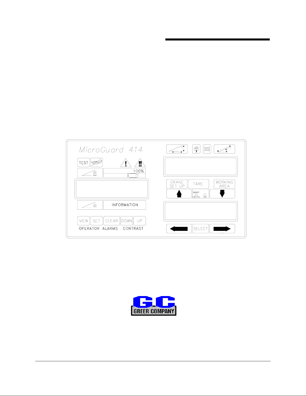
MICROGUARD
MICROGUARD
MICROGUARDMICROGUARD
Crane Systems
Crane Systems
Crane SystemsCrane Systems
414
414
414 414
RATED CAPACITY INDICATOR (RCI)
SYSTEM
SYSTEM
SYSTEMSYSTEM
LATTICE BOOM CRANES
LATTICE BOOM CRANES
LATTICE BOOM CRANESLATTICE BOOM CRANES
HORIZONTAL DISPLAY
HORIZONTAL DISPLAY
HORIZONTAL DISPLAYHORIZONTAL DISPLAY
CLYDE M4190
CLYDE M4190
CLYDE M4190CLYDE M4190
BARGE MOUNT
BARGE MOUNT
BARGE MOUNTBARGE MOUNT
OPERATOR'S MANUAL
OPERATOR'S MANUAL
OPERATOR'S MANUALOPERATOR'S MANUAL
GREER COMPANY 1918 East Glenwood Place, Santa Ana, CA 92705 Tel: 714) 259-9702 Fax: 714) 259-7626 PN W414107-
MicroGuard 414 System Lattice Boom Cranes Horizontal Display Clyde M4190 Barge Mount OPERATOR'S MANUAL 12/20/01
1 of 21
Page 2

GREER COMPANY
GREER COMPANY
GREER COMPANYGREER COMPANY
The MicroGuard 414 Rated Capacity Indicator System (RCI) for
Lattice Boom Cranes – Horizontal Display – Clyde M4190
Barge Mount is designed to aid the fully trained and experienced
crane operator in safe crane operation. This System may not be
used as a substitute for the usual safety practices and
precautions required for the safe setup and operation of cranes.
Crane Systems
Crane Systems
Crane SystemsCrane Systems
WARNING
WARNING
WARNINGWARNING
GREER COMPANY 1918 East Glenwood Place, Santa Ana, CA 92705 Tel: 714) 259-9702 Fax: 714) 259-7626 PN W414107-
MicroGuard 414 System Lattice Boom Cranes Horizontal Display Clyde M4190 Barge Mount OPERATOR'S MANUAL 12/20/01
2 of 21
Page 3

GREER COMPANY
GREER COMPANY
GREER COMPANYGREER COMPANY
Crane Systems
Crane Systems
Crane SystemsCrane Systems
TABLE OF CONTENTS
TABLE OF CONTENTS
TABLE OF CONTENTSTABLE OF CONTENTS
GENERAL WARNING................................................................................................................................... 2
SYSTEM DESCRIPTION .............................................................................................................................. 4
THE DISPLAY – UPPER LEFT........................................................................................................5
THE DISPLAY – UPPER/LOWER RIGHT ....................................................................................... 6
PUSH BUTTONS – LAMPS – ICONS ..................................................................................................... 7-10
THE DISPLAY – LEFT .................................................................................................................. 7-8
THE DISPLAY – UPPER RIGHT ..................................................................................................... 9
THE DISPLAY – LOWER RIGHT .................................................................................................. 10
SYSTEM OPERATION ............................................................................................................................... 11
CONFIGURATION SELECTION............................................................................................................12-13
CRANE SETUP.............................................................................................................................. 12
DUAL USE PUSH BUTTONS ........................................................................................................ 12
OPERATOR SETTABLE ALARMS ........................................................................................................14-17
SETTING ALARMS – METHOD ...............................................................................................15-16
SETTING ALARMS – EXAMPLES A-C ....................................................................................16-17
CANCELING ALARMS................................................................................................................... 18
PERIODIC INSPECTIONS.......................................................................................................................... 19
SYSTEM CHECKS......................................................................................................................... 20
ROUTINE MAINTENANCE............................................................................................................ 20
GREER COMPANY 1918 East Glenwood Place, Santa Ana, CA 92705 Tel: 714) 259-9702 Fax: 714) 259-7626 PN W414107-
MicroGuard 414 System Lattice Boom Cranes Horizontal Display Clyde M4190 Barge Mount OPERATOR'S MANUAL 12/20/01
3 of 21
Page 4
GREER COMPANY
GREER COMPANY
GREER COMPANYGREER COMPANY
SYSTEM DESCRIPTION
SYSTEM DESCRIPTION
SYSTEM DESCRIPTIONSYSTEM DESCRIPTION
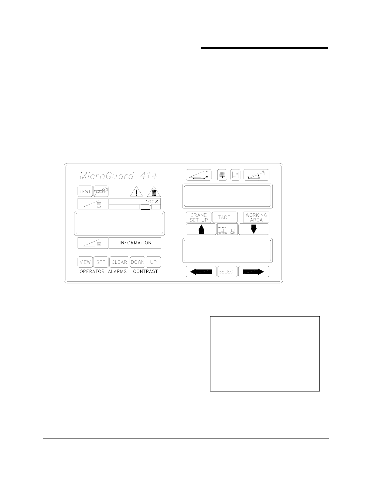
The MicroGuard® 414 Rated Capacity Indicator (RCI) System for lattice boom cranes is intended to aid
the crane operator in efficient crane operation by continuously monitoring the load and warning the
operator of an approaching overload or Two-Block condition. Monitoring crane functions is accomplished
with the use of highly accurate sensors that continuously compare the load suspended below the boom
head with a copy of the crane capacity chart stored in the computer memory. When an approaching
overload or Two-Block condition is sensed by the system, audible and visual alarms activate. This
System can also be configured to cause cessation of boom movement – winch up, boom down, and
extend out (function kick-out).
The MicroGuard
MicroGuard
®
414 Rated Capacity Indicator (RCI) System for lattice boom cranes is used with the
®
Rated Capacity Indicator (RCI) 414 Display.
Crane Systems
Crane Systems
Crane SystemsCrane Systems
®
The MicroGuard
♦ Rated Capacity
♦ Actual Load
♦ Percentage of Rated Capacity
♦ Radius of the Load
♦ Angle of the Main Boom
♦ Working Area (if applicable)
♦ Crane Configuration
Use of alternate display push buttons provide the operator with:
♦ Length of the Main Boom.
♦ Height of the Boom Head.
GREER COMPANY 1918 East Glenwood Place, Santa Ana, CA 92705 Tel: 714) 259-9702 Fax: 714) 259-7626 PN W414107-
MicroGuard 414 System Lattice Boom Cranes Horizontal Display Clyde M4190 Barge Mount OPERATOR'S MANUAL 12/20/01
414 System provides the operator with a continuous display of:
On-screen messages relate to various
alarms that may occur during normal
operation of the system. These
messages are displayed in the left and
upper right displays. The lower right
display provides information about the
currently selected crane configuration.
4 of 21
Page 5
GREER COMPANY
GREER COMPANY
GREER COMPANYGREER COMPANY
THE DISPLAY
THE DISPLAY –––– UPPER
THE DISPLAY THE DISPLAY
MicroG uard
TEST
W
MAX
1
5
is the ROPE CAPACITY and the message, ROPE LIMIT will appear in the information area (4).
5.82
3.46
W
VIEW SET CLEAR DOW N UP
Crane Systems
Crane Systems
Crane SystemsCrane Systems
UPPER LEFT
UPPER UPPER
LEFT
LEFTLEFT
424
100%
60%
ATB ALARM
INFO RM ATION
CO NTRASTOPERATOR ALARM S
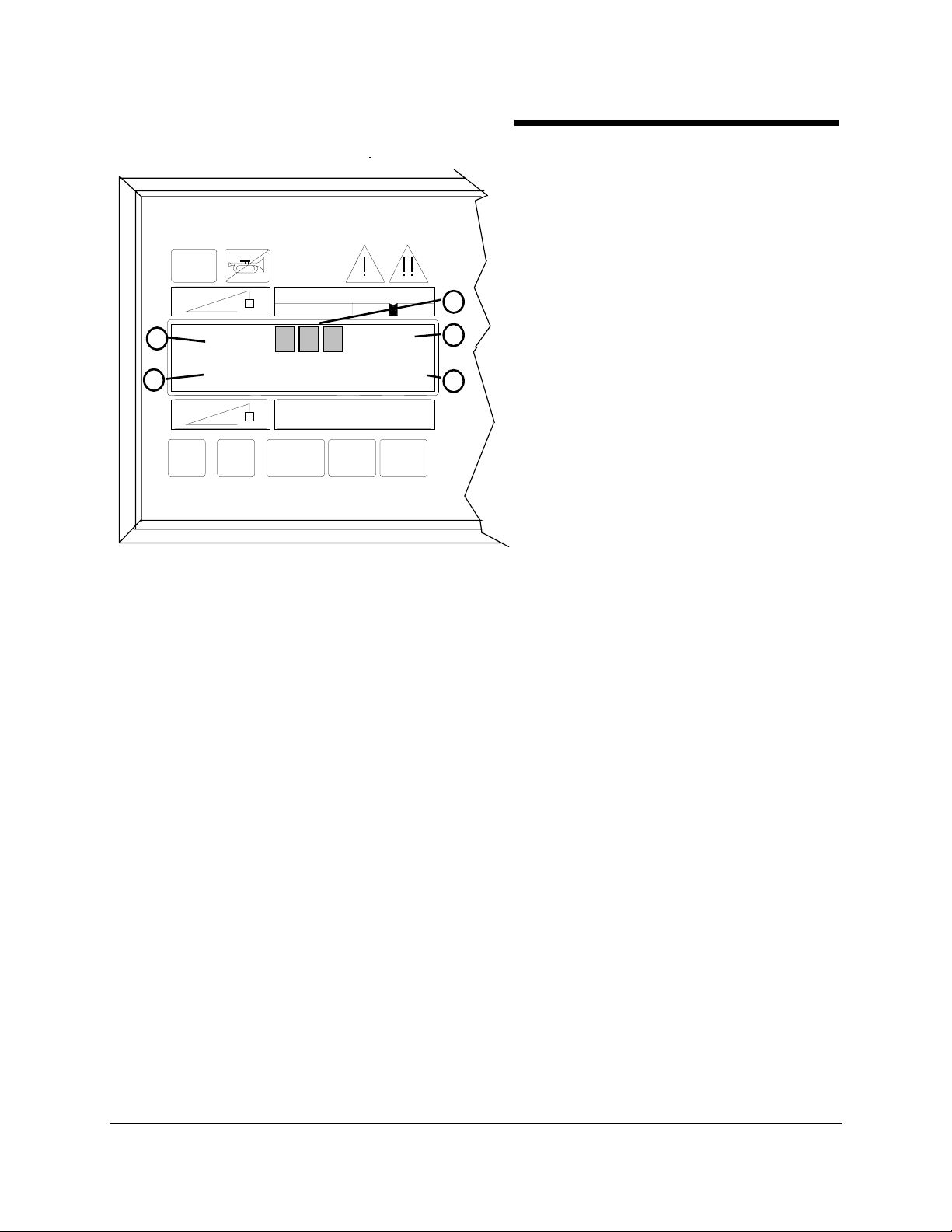
MAXMUM RATED CAPACITY (1)
is the maximum permitted capacity of the
crane. This value, which appears digitally in
the left display, is derived from a copy of the
crane's capacity chart stored in the memory
of the computer.
2
3
4
MAXIMUM RATED CAPACITY is the
reference capacity for any lifting operation
and is dependent on the crane configuration
currently selected. The currently selected
configuration must be the same as the actual
configuration. The current selection may be
viewed in the lower right display. The crane
configuration determines the section of the
capacity chart used as the capacity
reference. If the MAXIMUM RATED
CAPACITY is limited by parts-of-line, the
DISPLAYED MAXIMUM RATED CAPACITY
The BAR GRAPH (2) is an analog BAR GRAPH that shows the amount of crane capacity being used
and the rate at which an overload is being approached. This BAR GRAPH in conjunction with the 100%
capacity marker visually indicates when an overload point is reached.
PERCENT OF RATED CAPACITY (3) is shown as a digital read out in which Actual Load appears as
a percentage of Maximum Rated Capacity. For percentages less than 100%, the read out will be at the
right side of the bar graph. For percentages over 87%, the display will move to the center of the bar graph
to make space for the leading edge of the bar graph.
The INFORMATION AREA (4) provides the operator with a visual indicator of the various alarms that
may occur during normal operation of the system. For example, PRE-ALARM, OVERLOAD, ATB ALARM,
or ROPE LIMIT.
ACTUAL LOAD (5) is a digital display that shows the total load suspended below the boom or jib head.
It includes the load, slings, pins, or tackle used to secure the load, and the hook block. Using the
STOWED DEDUCT button, the operator can "tare out” the slings and hook (see page 9).
GREER COMPANY 1918 East Glenwood Place, Santa Ana, CA 92705 Tel: 714) 259-9702 Fax: 714) 259-7626 PN W414107-
MicroGuard 414 System Lattice Boom Cranes Horizontal Display Clyde M4190 Barge Mount OPERATOR'S MANUAL 12/20/01
5 of 21
Page 6
GREER COMPANY
GREER COMPANY
GREER COMPANYGREER COMPANY
Crane Systems
Crane Systems
Crane SystemsCrane Systems
THE DISPLAY
THE DISPLAY –––– UPPER/LOWER R
THE DISPLAY THE DISPLAY
UPPER/LOWER RIIIIGHT
UPPER/LOWER RUPPER/LOWER R
GHT
GHTGHT
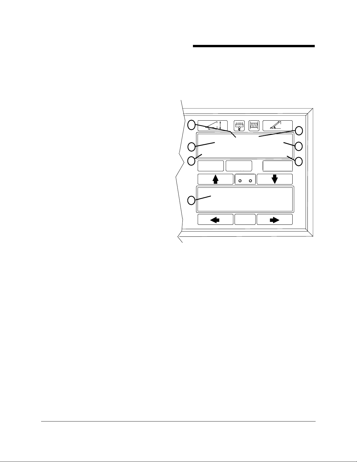
Refer to the illustration below.
RADIUS/HEIGHT (1) gives a continuous indication of the radius of the load, which is the horizontal
distance from the centerline of rotation to the centerline of the hook. When the Radius/Height push button
is pressed, the display will give a momentary read
out of the height of the boom head above ground
level, i.e. the vertical distance from the ground to
the boom/jib head. Information about height is
only displayed while the Radius/Height push
button is pressed and held.
PARTS-OF-LINE (2) shows the parts-of-line
currently selected. If the parts-of-line selected has
a lower safe working strength than the actual
capacity, the MAXIMUM RATED CAPACITY
display will show the reduced capacity and the
message, "ROPE LIMIT" will be displayed in the
information area.
2
57.2
1
8 F
BARGE MOUNT
6
CRAN E
SET UP
STOWED
TARE
DEDUCT
DEDUCT
ERECTED
LIFTING POINT
7
150 FT MAIN BOOM
3
49.1
360°
WOR KIN G
AREA
4
5
WINCH IN USE (3) indicates the selected
winch. "M" = MAIN, "A" = AUXILIARY,
SELECT
"F" = FRONT, and "R" = REAR.
ANGLE/LENGTH (4) gives a continuous
indication of the angle of the main boom relative to its horizontal position. When the angle/length push
button is pressed and held, the display will give a momentary read out of the length of the Main Boom
from the boom foot pin to the shaft of the head machinery. Information about length is only displayed while
the Angle/Length push button is pressed and held.
THE BARGE MOUNT SELECTION (6) shown in the lower left of the upper right display is
determined by the current duty selection.
THE LIFTING POINT-150 FT FROM MAIN BOOM CONFIGURATION (7) is continuously
displayed on the upper line of the lower display.
The WORKING AREA (5) is in the lower right section of the upper right display. Descriptions conform
to the current configuration selected and to the swing position of the crane upper. On this crane, it will only
display 360° (AS SHOWN).
GREER COMPANY 1918 East Glenwood Place, Santa Ana, CA 92705 Tel: 714) 259-9702 Fax: 714) 259-7626 PN W414107-
MicroGuard 414 System Lattice Boom Cranes Horizontal Display Clyde M4190 Barge Mount OPERATOR'S MANUAL 12/20/01
6 of 21
Page 7
GREER COMPANY
GREER COMPANY
GREER COMPANYGREER COMPANY
PUSH BUTTONS -- LAMPS -- ICONS
PUSH BUTTONS -- LAMPS -- ICONS
PUSH BUTTONS -- LAMPS -- ICONSPUSH BUTTONS -- LAMPS -- ICONS
14
TEST
8
7
VIEW SET CLEAR DOWN UP
9
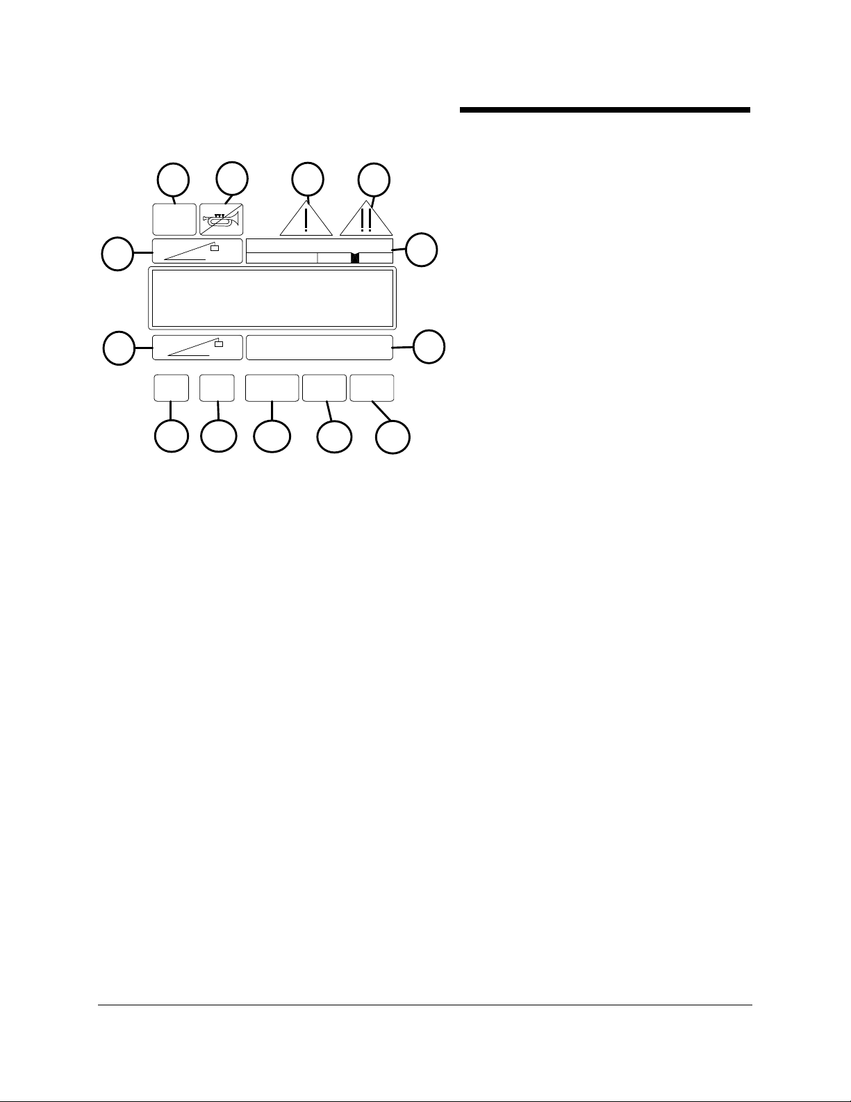
The AMBER
AMBER PRE
AMBERAMBER
and provides a visual indication of an approach to an overload.
2
W
MAX
LEFT DISPLAY
W
10
PRE----ALARM
ALARM (3)
PREPRE
ALARMALARM
Crane Systems
Crane Systems
Crane SystemsCrane Systems
THE DISPLAY -- LEFT
THE DISPLAY -- LEFT
THE DISPLAY -- LEFTTHE DISPLAY -- LEFT
3
100%
INFORMATION
11
12
(3) icon illuminates at a pre-set value of 90% of Maximum Rated Capacity
(3)(3)
13
Please refer to the callouts for the push
buttons in the illustration shown.
TEST
TEST (1) initiates a System self-test and also
TESTTEST
5
used to display fault codes.
CANCEL ALARM
CANCEL ALARM (2) silences the audible
CANCEL ALARMCANCEL ALARM
alarm when the alarm has occurred as a result of
an Overload, an Anti Two-Block alarm or an
Operator Settable alarm. This button is also
6
used to reset the function kick-out relay when it is
necessary to by-pass function kick-out.
The OVERLOAD INDICATOR (RED)
OVERLOAD INDICATOR (RED) (4) icon illuminates at a pre-set value of 100% of Maximum
OVERLOAD INDICATOR (RED)OVERLOAD INDICATOR (RED)
Rated Capacity and provides a visual indication of Maximum Allowed Load. It will also illuminate whenever
an Anti Two-Block alarm occurs, a wire rope limit is exceeded, or an operator settable alarm has been
reached or exceeded. When the crane is equipped with function kick-out, this indicator will illuminate
simultaneously for Overload, Wire Rope Limit, or an Anti Two-Block condition. Function kick-out will not
occur when exceeding an operator set alarm.
The BA
BAR GRAPH
R GRAPH (5) is a part of the analog bar graph in the left display. The bar graph indicates the
BABA
R GRAPH R GRAPH
crane capacity being used and the rate at which an overload is being approached. The leading edge of the
bar graph aligns with three colored bands in the bar graph indicator. Red indicates an overload. Between
the red and amber is a black notch that indicates 100% of rated capacity. The 100% RATED CAPACITY
INDICATOR is above the bar graph in the left display and marks the point at which 100% of the rated
capacity of the crane has been reached. When the value of 100% has been reached, it corresponds to the
Maximum Rated Capacity in the left display.
The INFORMATION AREA
INFORMATION AREA (6) provides the operator with a visual indication of the various alarms that
INFORMATION AREAINFORMATION AREA
may occur during normal operation of the system. Such data will appear in the line above the letters,
“INFORMATION.”
The ACTUAL LOAD ICON
ACTUAL LOAD ICON (7) indicates the area of the display showing the total load suspended
ACTUAL LOAD ICONACTUAL LOAD ICON
below the boom, fly, or jib head. It includes the load, any slings, pins, or tackle used to secure the load and
the weight of the hook block. The system will allow the operator to "tare out” the weight of slings and hook
(see page 9).
The MAXIMUM RATED CAPACITY ICON
MAXIMUM RATED CAPACITY ICON (8) indicates the area of the left display that gives a read
MAXIMUM RATED CAPACITY ICONMAXIMUM RATED CAPACITY ICON
out of maximum rated capacity for the currently selected configuration.
GREER COMPANY 1918 East Glenwood Place, Santa Ana, CA 92705 Tel: 714) 259-9702 Fax: 714) 259-7626 PN W414107-
MicroGuard 414 System Lattice Boom Cranes Horizontal Display Clyde M4190 Barge Mount OPERATOR'S MANUAL 12/20/01
7 of 21
Page 8
GREER COMPANY
GREER COMPANY
GREER COMPANYGREER COMPANY
Crane Systems
Crane Systems
Crane SystemsCrane Systems
PUSH BUTTONS -- LAMPS -- ICONS
PUSH BUTTONS -- LAMPS -- ICONS
PUSH BUTTONS -- LAMPS -- ICONSPUSH BUTTONS -- LAMPS -- ICONS
THE DISPLAY
THE DISPLAY -- LEFT
THE DISPLAY THE DISPLAY
14
TEST
8
7
VIEW SET CLEAR DOWN UP
9
SETTING THE OPERATOR ALARMS
2
W
MAX
LEFT DISPLAY
W
10
INFORMATION
11
3
100%
12
13
5
6
-- LEFT continued
-- LEFT-- LEFT
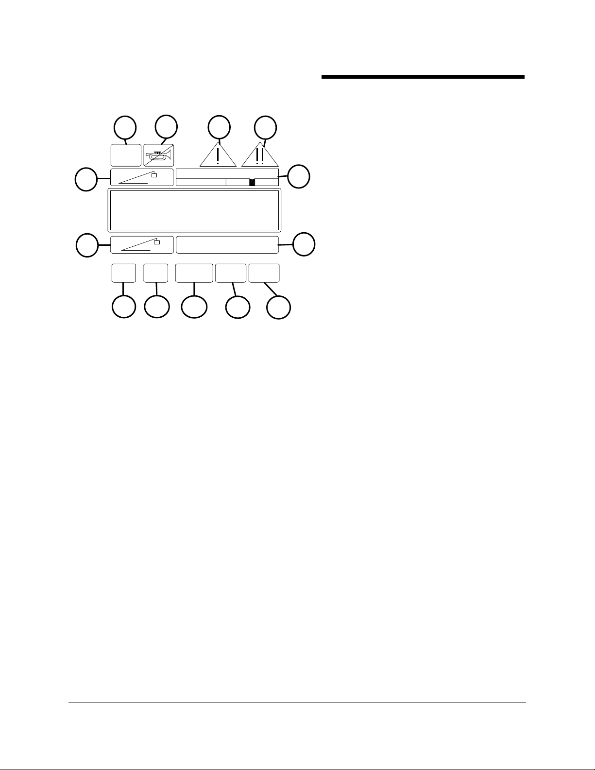
Please refer to the push button callouts in the above illustration.
VIEW ((((9)))) starts the operator alarm routine and permits viewing of the current alarm settings.
SET (
(10) creates a new alarm setting.
( (
CLEAR ((((11) clears a current alarm.
CONTRAST (DOWN) (12) decreases the display contrast.
CONTRAST (UP) (13) increases the display contrast.
GREER COMPANY 1918 East Glenwood Place, Santa Ana, CA 92705 Tel: 714) 259-9702 Fax: 714) 259-7626 PN W414107-
MicroGuard 414 System Lattice Boom Cranes Horizontal Display Clyde M4190 Barge Mount OPERATOR'S MANUAL 12/20/01
8 of 21
Page 9
GREER COMPANY
GREER COMPANY
GREER COMPANYGREER COMPANY
PUSH BUTTONS -- LAMPS -- ICONS
PUSH BUTTONS -- LAMPS -- ICONS
PUSH BUTTONS -- LAMPS -- ICONSPUSH BUTTONS -- LAMPS -- ICONS
THE DISPLAY
THE DISPLAY -- UPPER RIGHT
THE DISPLAY THE DISPLAY
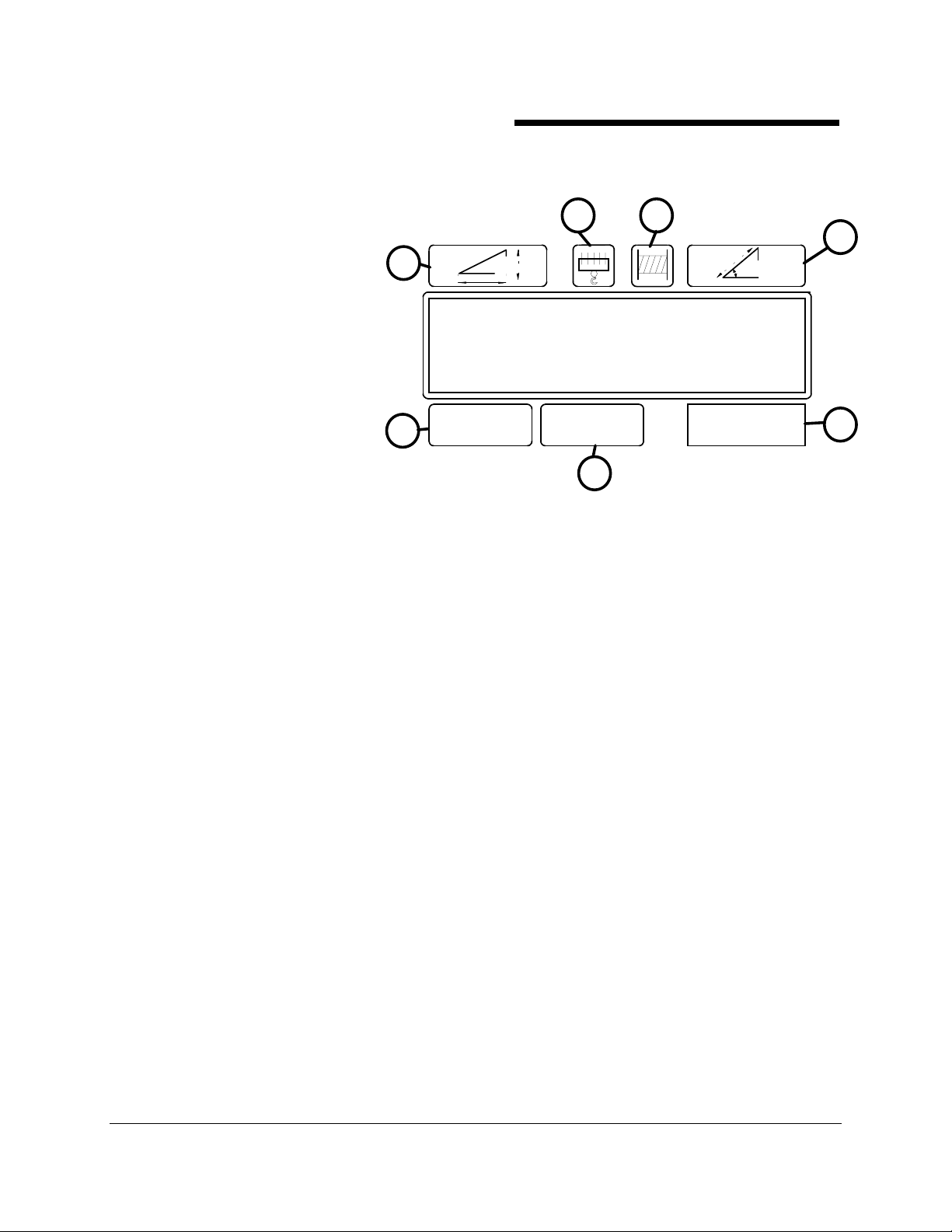
RADIUS/HEIGHT
RADIUS/HEIGHT shows the
RADIUS/HEIGHT RADIUS/HEIGHT
current radius and height. Height is
displayed only when the push button
is pressed and held.When the push
button is not pressed, the read out
is always shown as the radius of
the load.
PARTS
PARTS----OF
PARTSPARTS
view the current parts-of-line and to
select the parts-of-line in use on the
selected winch.
WINCH (
WINCH (3)
WINCH (WINCH (
currently selected. This button is
used to alternate between the front
and rear winch. When switching between winches, the parts-of-line previously selected and recorded for
each winch will be displayed whenever a particular winch is selected.
OF----LINE
LINE (20) is used to
OFOF
LINELINE
3) identifies the winch
3)3)
Crane Systems
Crane Systems
Crane SystemsCrane Systems
UPPER RIGHT
UPPER RIGHTUPPER RIGHT
1
7
CRANE
SET UP
23
UPPER RIGHT DISPLAY
STOWED
TARE
DEDUCT
6
WORKING
AREA
4
5
ANGLE/LENGTH
ANGLE/LENGTH (4) provides a read out of angle or length. Length is displayed only when the push
ANGLE/LENGTHANGLE/LENGTH
button is pressed and held. When the push button is not pressed, the read out is always shown as the
Angle of the main boom.
WORKING AREA
WORKING AREA (5555) receives and displays messages. Messages received in this area will conform to
WORKING AREAWORKING AREA
the current duty selection and the swing position of the crane upper for cranes with swing and multiple
working swing areas.
TARE (6)
TARE (6) extracts or "tares out" the weight of hook and slings. When pushed, this button will show the
TARE (6) TARE (6)
actual weight of the load being lifted without the weight of the hooks and slings..
TO SET
TO SET TARE
TO SETTO SET
display console will then beep and "zero" the actual load display. The TARE lamp will then illuminate to
indicate that a tare has been set.
TO CLEAR TARE
TO CLEAR TARE Press the TARE button. The display console will immediately beep, the actual load
TO CLEAR TARETO CLEAR TARE
display will show the total weight below the boom head, and the TARE lamp will be off.
CRANE SETUP (7)
CRANE SETUP (7) indicates the area of the display that provides a read out of the selected
CRANE SETUP (7) CRANE SETUP (7)
configuration. This icon is also a push button used to start the selection of the crane configuration.
TARE With the hook and slings lifted, press & hold the TARE button (6) for three seconds. The
TARE TARE
GREER COMPANY 1918 East Glenwood Place, Santa Ana, CA 92705 Tel: 714) 259-9702 Fax: 714) 259-7626 PN W414107-
MicroGuard 414 System Lattice Boom Cranes Horizontal Display Clyde M4190 Barge Mount OPERATOR'S MANUAL 12/20/01
9 of 21
Page 10
GREER COMPANY
GREER COMPANY
GREER COMPANYGREER COMPANY
PUSH BUTTONS -- LAMPS -- ICONS
PUSH BUTTONS -- LAMPS -- ICONS
PUSH BUTTONS -- LAMPS -- ICONSPUSH BUTTONS -- LAMPS -- ICONS
THE DISPLAY -- LOWER RIGHT
THE DISPLAY -- LOWER RIGHT
THE DISPLAY -- LOWER RIGHTTHE DISPLAY -- LOWER RIGHT
1
6
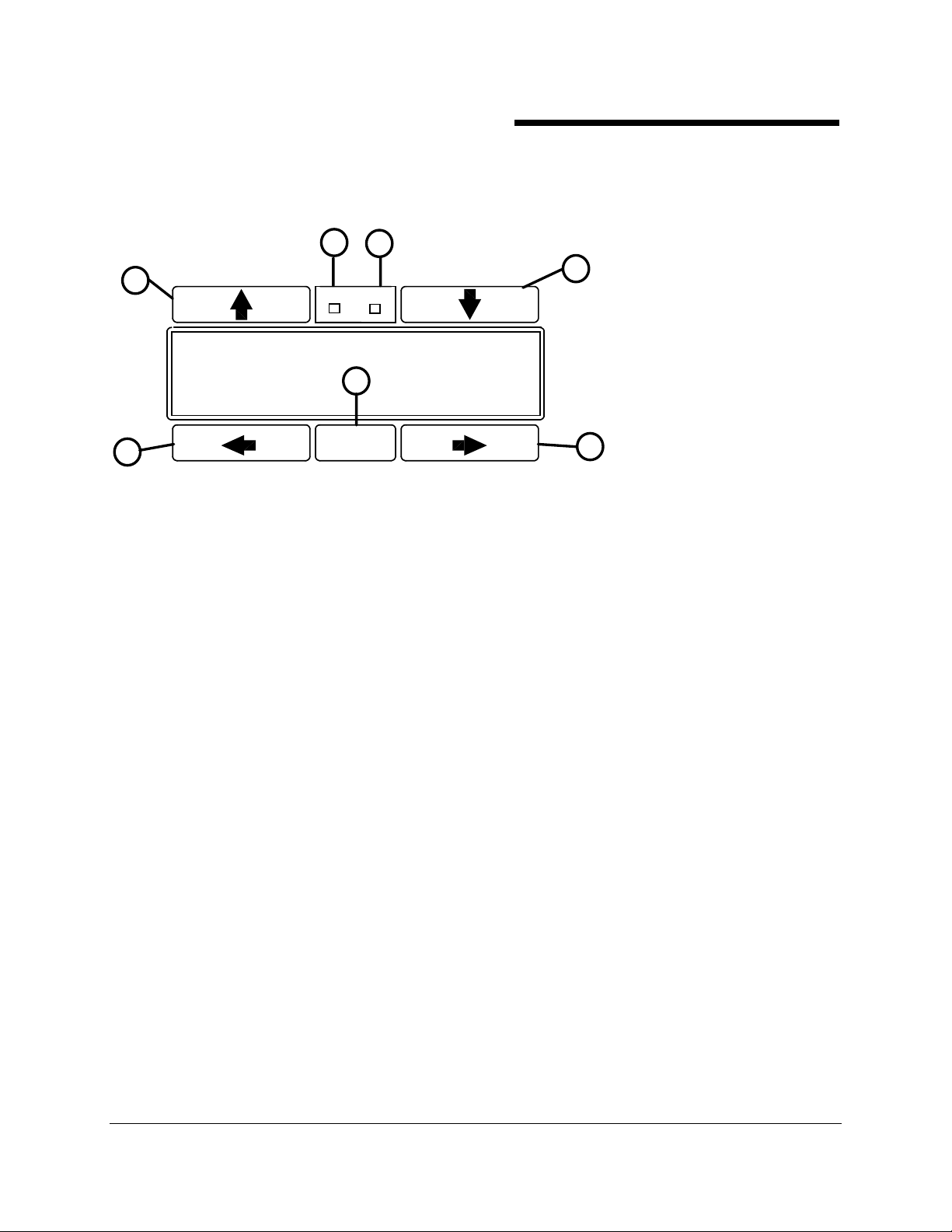
Please refer to the following callouts in the illustration above.
The DEDUCT INDICATOR (2)
DEDUCT INDICATOR (2) is an amber lamp that indicates erected deducts. When a deduct is
DEDUCT INDICATOR (2) DEDUCT INDICATOR (2)
selected, the lamp will illuminate to warn the operator that a deduct has been applied to the allowed load.
The deduct function only applies to cranes that have boom attachments.
Crane Systems
Crane Systems
Crane SystemsCrane Systems
23
DEDUCT
TARE
ERECTED STOWED
LOWER RIGHT DISPLAY
5
SELECT
4
UP/DOWN ARROWS
UP/DOWN ARROWS 1 & 4
UP/DOWN ARROWSUP/DOWN ARROWS
are push buttons used for scrolling.
7
1 & 4
1 & 41 & 4
TARE
TARE (3)
TARETARE
(page 9).
SELECT
SELECT (5)
SELECTSELECT
RIGHT AND LEFT ARROWS
RIGHT AND LEFT ARROWS ((((6 &7)
RIGHT AND LEFT ARROWSRIGHT AND LEFT ARROWS
(3) is an amber lamp that illuminates when the actual load value displayed has been "tared" out
(3)(3)
(5) is a push button used to terminate all selection and calibration routines.
(5)(5)
6 &7) are push buttons used in calibration routines.
6 &7) 6 &7)
GREER COMPANY 1918 East Glenwood Place, Santa Ana, CA 92705 Tel: 714) 259-9702 Fax: 714) 259-7626 PN W414107-
MicroGuard 414 System Lattice Boom Cranes Horizontal Display Clyde M4190 Barge Mount OPERATOR'S MANUAL 12/20/01
10 of 21
Page 11

GREER COMPANY
GREER COMPANY
GREER COMPANYGREER COMPANY
SYSTEM OPERATION
SYSTEM OPERATION
SYSTEM OPERATIONSYSTEM OPERATION
After performing an automatic self-test at start-up, the system goes directly to the normal working screen.
The self-test can be initiated at any time during normal operation by pressing the TEST button.
TEST
TEST
TESTTEST
One press (press and release) will cause the system to execute a self-test routine at any time. All lamps,
audible alarms, and digital displays will be functionally tested and all memory areas checked for accuracy
during a self-test. If faults in the system are detected, the information area in the upper display will show
the word "FAULT." If the word FAULT occurs,
display to change to the FAULT MODE. In this mode, information about the fault condition will be
displayed in the upper right display via an error code.
CANCEL ALARM
CANCEL ALARM
CANCEL ALARMCANCEL ALARM
The CANCEL ALARM button is used to cancel the audible alarm after the alarm has occurred as a result
of an OVERLOAD, an ANTI TWO-BLOCK ALARM or an OPERATOR SETTABLE ALARM. The audible
alarm may be canceled by pressing and releasing the CANCEL ALARM button.
The audible alarm remains canceled until the condition causing the alarm has been removed.
For example, if the audible alarm was canceled because of an overload condition, it will remain canceled
until the overload condition is removed. However, if a different alarm, e.g. an anti two-block condition,
occurred when the audible alarm was still canceled for an earlier overload condition, the new alarm
condition would cause the audible alarm to be restarted.
Crane Systems
Crane Systems
Crane SystemsCrane Systems
press and hold
the TEST button. This will cause the
CANCEL ALARM
CANCEL ALARM is also used to reset the function kick-out relay when it is necessary to by-pass
CANCEL ALARMCANCEL ALARM
function kick-out that has occurred as a result of either an overload or an A.T.B. alarm. The relay is
re-set by first canceling the audible alarm [as described above] and then pressing and holding the
CANCEL ALARM button for about 3 seconds. The function kick-out relay will then be set to normal
operation. However, should another different alarm condition occur when the relay had previously been
overridden, then the newly occurring alarm condition would cause the motion cut to be re-started.
CANCEL ALARM
when the condition, which caused the alarm, is no longer present.
WARNING
WARNING
WARNINGWARNING
is a temporary function. The audible alarm or function kick-out is automatically reset
WHEN FUNCTION KICK-OUT IS RESET USING THE CANCEL ALARM BUTTON,
THERE IS NO LONGER PROTECTION AGAINST THE CONDITION THAT CAUSED
THE FUNCTION KICK-OUT.
GREER COMPANY 1918 East Glenwood Place, Santa Ana, CA 92705 Tel: 714) 259-9702 Fax: 714) 259-7626 PN W414107-
MicroGuard 414 System Lattice Boom Cranes Horizontal Display Clyde M4190 Barge Mount OPERATOR'S MANUAL 12/20/01
11 of 21
Page 12

GREER COMPANY
GREER COMPANY
GREER COMPANYGREER COMPANY
CON
CONFIGURATION SELECTION
CONCON
In the normal operational mode, the system is programmed to remember the configuration last selected.
Each time the system is powered up, it will automatically choose that configuration. Only when the crane is
rigged differently must a new configuration be selected.
CRANE SET UP
CRANE SET UP
CRANE SET UPCRANE SET UP
The menu for the crane set up consists of two consecutive steps.
1. Select auxiliary tip or no erected attachment.
2. Select boom configuration (lifting from main or aux hoist).
FIGURATION SELECTION
FIGURATION SELECTIONFIGURATION SELECTION
• AFTER COMPLETING THE SELECTIONS FOR CRANE SET UP, USE THE WINCH
PUSH BUTTON TO SELECT THE LIFTING POINT.
• ALL OF THE INFORMATION REQUIRED BY THE SYSTEM IS ENTERED
DURING CRANE SET-UP.
• ENSURE THAT THE PARTS-OF-LINE IN USE FOR EACH WINCH IS SET. IF NOT, THE
SYSTEM WILL NOT OPERATE CORRECTLY.
FOR SPECIFIC EXAMPLES OF CRANE SET-UP, REFER TO PAGE 14.
Crane Systems
Crane Systems
Crane SystemsCrane Systems
PARTS
PARTS----OF
PARTSPARTS
Press and hold the PARTS-OF-LINE push button to scroll through the available parts-of-line. The new
value is automatically registered when the button is released. The number chosen applies only to the
winch currently selected. A value must be programmed for both winches.
WINCH
WINCH
WINCHWINCH
The current selection is shown on the display by selecting the letter "M" for MAIN winch and the letter
"A" FOR AUX WINCH. To change the selection, press the winch select push button. Successive pressing
of this button will change the selection from one to the other. After the initial setup, the system records and
retains the parts-of-line and lifting point for each winch.
DUAL USE PUSH BUTTONS
DUAL USE PUSH BUTTONS
DUAL USE PUSH BUTTONSDUAL USE PUSH BUTTONS
Some push buttons provide two kinds of information. These are the RADIUS/HEIGHT and
LENGTH/ANGLE push buttons.
RADIUS/HEIGHT
RADIUS/HEIGHT When the RADIUS/HEIGHT
RADIUS/HEIGHTRADIUS/HEIGHT
display will ALWAYS show the CURRENT RADIUS.
When the SAME PUSH BUTTON is PRESSED AND HELD, the read out on the display will CHANGE TO
show the CURRENT HEIGHT. This information will remain on the display only as long as the operator
continues to press and hold this push button.
LENGTH/ANGLE
LENGTH/ANGLE When the LENGTH/ANGLE
LENGTH/ANGLELENGTH/ANGLE
display will ALWAYS show the current LENGTH.
OF----LINE
LINE
OFOF
LINELINE
RADIUS/HEIGHT push button is NOT PRESSED, the readout on the
RADIUS/HEIGHTRADIUS/HEIGHT
LENGTH/ANGLE push button is NOT PRESSED, the read out on the
LENGTH/ANGLELENGTH/ANGLE
When the SAME PUSH BUTTON is PRESSED AND HELD, the read out on the display will CHANGE to
show the ANGLE OF THE MAIN BOOM. This information will remain on the display only as long as the
operator continues to press and hold this push button.
GREER COMPANY 1918 East Glenwood Place, Santa Ana, CA 92705 Tel: 714) 259-9702 Fax: 714) 259-7626 PN W414107-
MicroGuard 414 System Lattice Boom Cranes Horizontal Display Clyde M4190 Barge Mount OPERATOR'S MANUAL 12/20/01
12 of 21
Page 13
GREER COMPANY
GREER COMPANY
GREER COMPANYGREER COMPANY
CONFIGURATION SELECTION
CONFIGURATION SELECTION
CONFIGURATION SELECTIONCONFIGURATION SELECTION
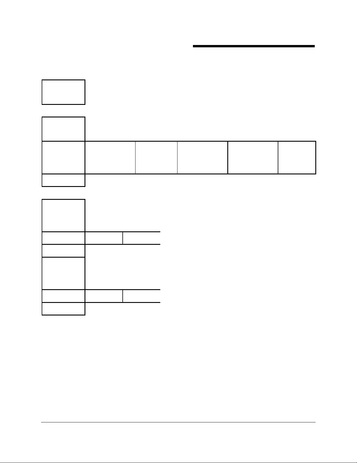
START THE SELECTION OF CRANE CONFIGURATION BY PRESSING "CRANE SET UP."
CRANE
SET UP
SCROLL TO
AUXILIARY TIP
×××× OR ØØØØ AUX TIP NO ERECTED
SELECT
SCROLL TO
Crane Systems
Crane Systems
Crane SystemsCrane Systems
ON RAIL
ATTACHMENTS
FULL
OUTRIGGERS
ON RAIL
W/O OUTRIGGERS
Rigging/Travel
Mode
MAIN WINCH
LIFTING POINT
×××× OR ØØØØ MAIN BOOM AUX TIP
SELECT
SCROLL TO
AUX WINCH
LIFTING POINT
×××× OR ØØØØ AUX TIP MAIN BOOM
SELECT
FOLLOWING THE SELECTION OF CRANE SET UP, USE THE WINCH PUSH BUTTON TO SELECT
THE LIFTING POINT. SET THE PARTS-OF-LINE IN USE FOR EACH WINCH USING THE PARTS-OFLINE PUSH BUTTON.
GREER COMPANY 1918 East Glenwood Place, Santa Ana, CA 92705 Tel: 714) 259-9702 Fax: 714) 259-7626 PN W414107-
MicroGuard 414 System Lattice Boom Cranes Horizontal Display Clyde M4190 Barge Mount OPERATOR'S MANUAL 12/20/01
13 of 21
Page 14
GREER COMPANY
GREER COMPANY
GREER COMPANYGREER COMPANY
OPERATOR SETTABLE ALARMS
OPERATOR SETTABLE ALARMS
OPERATOR SETTABLE ALARMSOPERATOR SETTABLE ALARMS
Another feature of the MicroGuard
alarms, when properly set by the operator, provide a method of obstacle avoidance. This is achieved by
means of minimum and maximum angle and maximum height alarms. These alarms can be programmed
for each job site and set rapidly for the prevailing site conditions, thereby aiding the operator in safe
operation of the crane.
Most alarms will occur automatically as a result of limitations imposed by the capacity chart. The operator
has control over additional alarms which can be set to define the working range of the crane for particular
site requirements and which will provide a measure of obstacle avoidance.
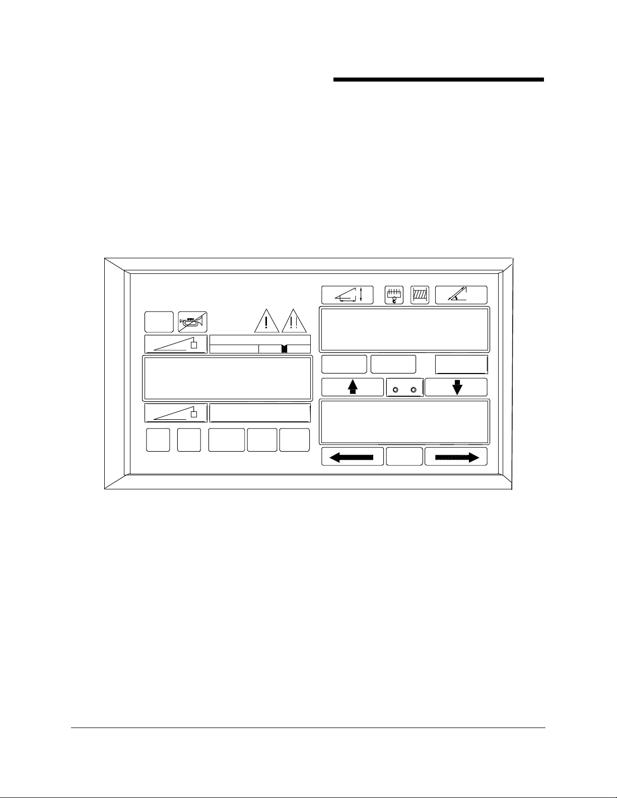
Three alarms are available for operator use.
MicroGuard 414
TEST
MIN ANGLE
MAX ANGLE
Crane Systems
Crane Systems
Crane SystemsCrane Systems
®
414 RCI System is the provision of Operator Settable Alarms. These
W
MAX
100%
31.5
75.4
MAX HEIGHT
CRANE
SETUP
TARE
DEDUCT
ERECTED
WORKING
TARE
AREA
98.5
W
VIEW SET CLEAR
OP ERAT OR ALAR MS
INFORMATION
DOW N UP
CONTRAST
MINIMUM ANGLE
MAXIMUM ANGLE
MAXIMUM HEIGHT
TAR E
SELEC T
GREER COMPANY 1918 East Glenwood Place, Santa Ana, CA 92705 Tel: 714) 259-9702 Fax: 714) 259-7626 PN W414107-
MicroGuard 414 System Lattice Boom Cranes Horizontal Display Clyde M4190 Barge Mount OPERATOR'S MANUAL 12/20/01
14 of 21
Page 15
GREER COMPANY
GREER COMPANY
GREER COMPANYGREER COMPANY
SETTING
SETTING ALARMS -- METHOD
SETTINGSETTING
WARNING:
WARNING: THE FOLLOWING EXAMPLES ILLUSTRATE THE METHOD FOR SETTING ALARMS.
WARNING:WARNING:
THE ACTUAL VALUES GIVEN SHOULD NOT BE USED WITHOUT FIRST CHECKING THE CAPACITY
CHART TO ENSURE SAFE, STABLE OPERATION UNDER THE CONDITIONS DESCRIBED.
ALARMS -- METHOD
ALARMS -- METHODALARMS -- METHOD
Crane Systems
Crane Systems
Crane SystemsCrane Systems
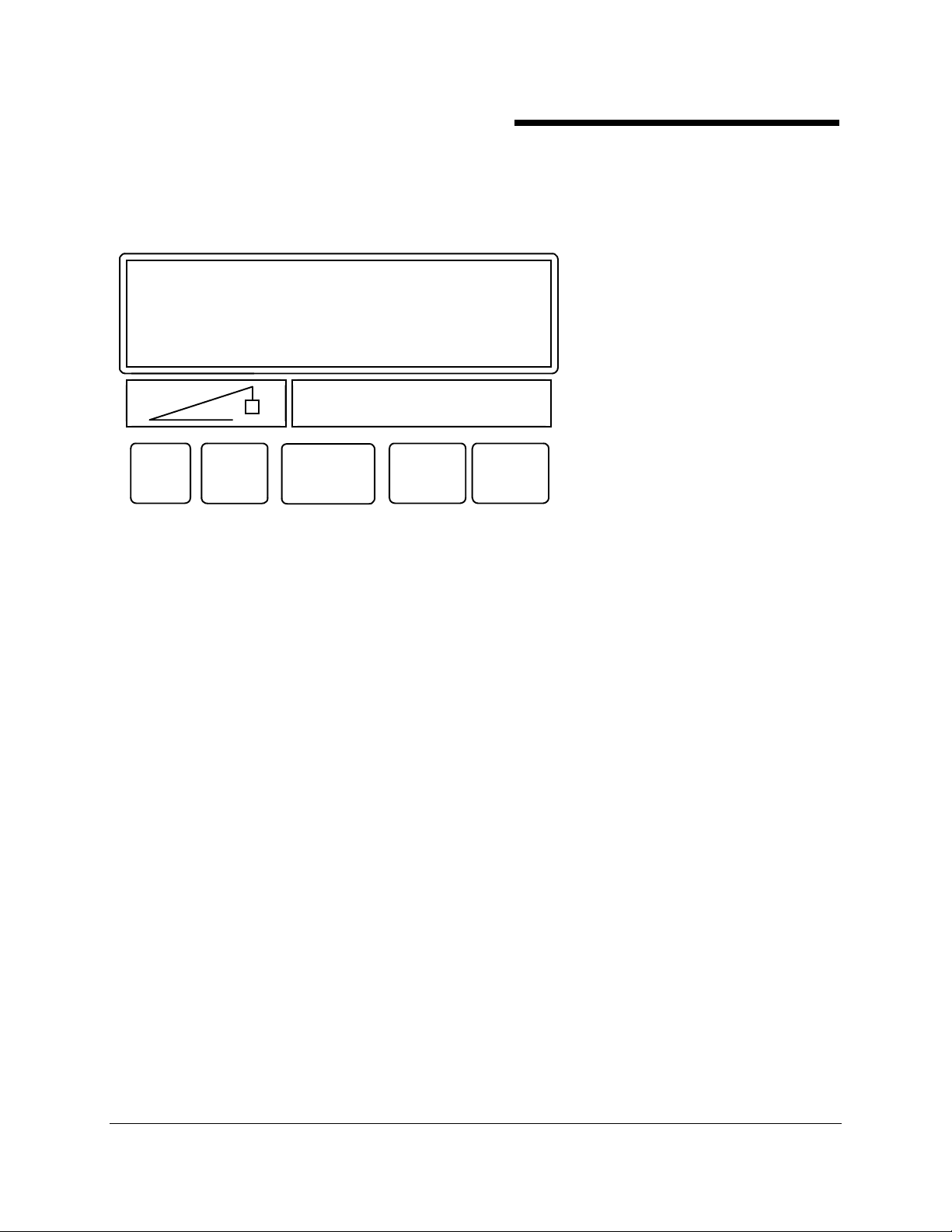
LEFT DISPLAY
W
VIEW
THE FOLLOWING PROCEDURE DESCRIBES THE METHOD REQUIRED FOR SETTING OR
CANCELING ALARMS.
SET
CLEAR
INFORMATION
DOWN UP
1. FROM THE MAIN WORKING SCREEN, PRESS VIEW TO ACCESS THE OPERATOR ALARM
SCREEN.
NOTE: SET OR CLEAR ALARMS ONLY FROM WITHIN THE ALARM SCREEN.
2. WHEN ENTERING THE ALARM SCREEN, THE CURSOR (ARROW) ALWAYS POINTS TO THE
FIRST ALARM. USING THE UP OR DOWN ARROWS, MOVE THE CURSOR TO THE ALARM
THAT MUST BE SET OR CLEARED.
3. PRESS SET OR CLEAR, AS APPROPRIATE.
NOTE:
NOTE: OPERATOR ALARMS ARE STORED IN THE COMPUTER MEMORY, EVEN AFTER THE
NOTE: NOTE:
CRANE IS SHUT DOWN.
NOTE:
NOTE: ALARMS THAT ARE NOT SET ARE INDICATED BY THE WORD "OFF."
NOTE:NOTE:
NOTE:
NOTE: WHEN THE CURSOR POINTS TO AN ALARM AND A NUMERICAL VALUE IS DISPLAYED,
NOTE:NOTE:
THE VALUE REPRESENTS THE CURRENT POSITION OF THE CRANE UNLESS THE
ALARM HAS BEEN SET PREVIOUSLY. IN THIS CASE, THE "VALUE" W ILL ALTERNATE
WITH THE WORD, "SET."
NOTE:
NOTE: AN ALARM SHOWING A VALUE WHEN THE CURSOR IS NOT POINTING AT THE ALARM
NOTE:NOTE:
INDICATES A PREVIOUSLY SET VALUE.
GREER COMPANY 1918 East Glenwood Place, Santa Ana, CA 92705 Tel: 714) 259-9702 Fax: 714) 259-7626 PN W414107-
MicroGuard 414 System Lattice Boom Cranes Horizontal Display Clyde M4190 Barge Mount OPERATOR'S MANUAL 12/20/01
15 of 21
Page 16

GREER COMPANY
GREER COMPANY
GREER COMPANYGREER COMPANY
THE FUNCTIONS OF THE PUSH BUTTONS WHEN IN THE ALARM SCREEN ARE:
♦♦♦♦ VIEW USED TO ACCESS THE ALARM SCREEN TO VIEW THE CURRENTLY SET ALARMS.
♦♦♦♦ SET USED TO SET THE ALARM VALUE. THE ALARM VALUE IS DETERMINED BY THE
POSITION OF THE CRANE AT THE TIME THE SET BUTTON IS PRESSED.
♦♦♦♦ CLEAR USED TO CLEAR A PREVIOUSLY SET ALARM. ALARMS CAN ONLY BE CLEARED
WHEN THE CURSOR IS POINTING TO THE ITEM TO BE CLEARED. USE THE UP/DOWN
ARROWS TO MOVE THE CURSOR TO THE DESIRED ALARM. PRESS CLEAR TO CANCEL
THAT ALARM.
♦♦♦♦ UP/DOWN ARROWS USED TO MOVE THE CURSOR UP OR DOWN THE SCREEN TO THE
ALARM, WHICH IS TO BE VIEWED, SET OR CLEARED.
♦♦♦♦ SELECT USED TO RETURN TO THE NORMAL OPERATING SCREEN.
SETTING THE ALARMS
SETTING THE ALARMS
SETTING THE ALARMSSETTING THE ALARMS
TO SET ALARM POINT POSITION THE CRANE AT THE POINT AT WHICH THE ALARM IS TO
SOUND. WHEN IN THE OPERATOR ALARM SCREEN, PRESS THE SET BUTTON TO SET THE
ALARM. REFER TO THE EXAMPLES BELOW.
Crane Systems
Crane Systems
Crane SystemsCrane Systems
EXAMPLE A
TO SET AN ALARM WHENEVER THE BOOM IS BELOW A 30° ANGLE:
1. PRESS VIEW TO ACCESS THE ALARM SCREEN. THE CURSOR W ILL BE AT MIN ANGLE.
2. MOVE THE BOOM TO A 30° ANGLE.
3. PRESS SET TO ENTER THE ALARM. THE DISPLAYED VALUE WILL BE THE ALARM SETTING,
WHICH W ILL ALTERNATE WITH THE WORD SET.
4. WHEN THE ALARM IS SET, PRESS SELECT TO RETURN TO THE W ORKING SCREEN.
THE RED LAMP AND THE AUDIBLE ALARM WILL OPERATE WHENEVER THE BOOM
IS BELOW 30°.THE MESSAGE MIN ANGLE WILL APPEAR IN THE INFORMATION AREA
ON THE LEFT DISPLAY.
EXAMPLE B
TO SET AN ALARM WHENEVER THE BOOM IS ABOVE A 60° ANGLE:
1. BOOM TO A 60° ANGLE.
2. PRESS SET TO ENTER THE ALARM. THE DISPLAYED VALUE WILL BE THE ALARM SETTING
AND IT WILL ALTERNATE WITH THE WORD SET. PRESS SELECT TO RETURN TO THE
WORKING SCREEN. THE RED LAMP AND THE AUDIBLE ALARM WILL OPERATE W HENEVER
THE BOOM IS ABOVE 60 DEGREES. THE MESSAGE MAX ANGLE WILL APPEAR IN THE
INFORMATION AREA ON THE LEFT DISPLAY.
GREER COMPANY 1918 East Glenwood Place, Santa Ana, CA 92705 Tel: 714) 259-9702 Fax: 714) 259-7626 PN W414107-
MicroGuard 414 System Lattice Boom Cranes Horizontal Display Clyde M4190 Barge Mount OPERATOR'S MANUAL 12/20/01
16 of 21
Page 17

GREER COMPANY
GREER COMPANY
GREER COMPANYGREER COMPANY
EXAMPLE C
TO HAVE AN ALARM WHENEVER THE BOOM TIP HEIGHT EXCEEDS 75 FEET, USE THE
FOLLOWING PROCEDURE.
1. EXTEND THE BOOM AND/OR ADJUST THE BOOM ANGLE SO THAT THE TIP HEIGHT IS 75
FEET.
2. PRESS VIEW TO ACCESS THE ALARM SCREEN. THE CURSOR W ILL BE AT MIN ANGLE.
PRESS THE DOWN ARROW TO MOVE THE CURSOR TO MAX HEIGHT.
3. PRESS SET TO ENTER THE ALARM. THE DISPLAYED VALUE WILL BE THE ALARM SETTING
AND IT WILL ALTERNATE WITH THE WORD SET. PRESS SELECT TO RETURN TO THE
WORKING SCREEN. THE RED LAMP AND THE AUDIBLE ALARM WILL OPERATE W HENEVER
THE BOOM TIP HEIGHT EXCEEDS 75 FEET. THE MESSAGE MAX HEIGHT WILL APPEAR IN
THE INFORMATION AREA ON THE LEFT DISPLAY.
Crane Systems
Crane Systems
Crane SystemsCrane Systems
GREER COMPANY 1918 East Glenwood Place, Santa Ana, CA 92705 Tel: 714) 259-9702 Fax: 714) 259-7626 PN W414107-
MicroGuard 414 System Lattice Boom Cranes Horizontal Display Clyde M4190 Barge Mount OPERATOR'S MANUAL 12/20/01
17 of 21
Page 18

GREER COMPANY
GREER COMPANY
GREER COMPANYGREER COMPANY
CANCELING ALARMS
CANCELING ALARMS
CANCELING ALARMSCANCELING ALARMS
CLEAR IS USED TO CANCEL A PREVIOUSLY SET ALARM. ALARMS CAN ONLY BE CLEARED
WHEN THE CURSOR IS POINTING TO THE ITEM TO BE CLEARED. CANCELING OF ALARMS CAN
BE CARRIED OUT REGARDLESS OF THE POSITION OF THE CRANE.
1. PRESS VIEW TO ACCESS THE ALARM SCREEN.
2. MOVE THE CURSOR TO POINT TO THE ALARM TO BE CANCELED.
3. PRESS CLEAR TO CANCEL THE ALARM. THE DISPLAYED VALUE WILL BE THE CURRENT
POSITION OF THE CRANE AND THE WORD SET WILL NO LONGER BE DISPLAYED.
4. MOVE THE CURSOR TO POINT TO THE NEXT ALARM TO BE CANCELED.
5. WHEN ALL THE CHOSEN ALARMS ARE CANCELED PRESS SELECT TO RETURN TO THE
WORKING SCREEN.
Crane Systems
Crane Systems
Crane SystemsCrane Systems
GREER COMPANY 1918 East Glenwood Place, Santa Ana, CA 92705 Tel: 714) 259-9702 Fax: 714) 259-7626 PN W414107-
MicroGuard 414 System Lattice Boom Cranes Horizontal Display Clyde M4190 Barge Mount OPERATOR'S MANUAL 12/20/01
18 of 21
Page 19

GREER COMPANY
GREER COMPANY
GREER COMPANYGREER COMPANY
PERIODIC INSPECTIONS
PERIODIC INSPECTIONS
PERIODIC INSPECTIONSPERIODIC INSPECTIONS
CHECKING T
CHECKING THE ANTI TWO BLOCK SYSTEM
CHECKING TCHECKING T
MAIN SWITCH
MAIN SWITCH
MAIN SWITCH MAIN SWITCH
1. LOWER THE BOOM SO THAT THE A.T.B. SWITCHES CAN BE REACHED BY HAND.
2. SET THE SELECTOR SW ITCH LOCATED ON THE MAIN SWITCH HOUSING TO THE "MAIN"
POSITION AND CHECK THAT RAISING THE WEIGHT TO TRIP THE SWITCH CAUSES THE
A.T.B. ALARM TO OPERATE.
JIB SWITCHES
JIB SWITCHES
JIB SWITCHESJIB SWITCHES
IF THE CRANE IS EQUIPPED WITH ADDITIONAL JIB SWITCHES, CHECK AS FOLLOWS.
1. CONNECT THE CABLE FROM THE JIB SWITCH TO THE RECEPTACLE ON THE MAIN SWITCH.
2. SET THE SELECTOR SW ITCH TO "BOTH".
3. CHECK THAT RAISING THE W EIGHT AND TRIPPING THE SWITCH ON EITHER THE MAIN OR
THE JIB SWITCH CAUSES THE A.T.B. ALARM TO OPERATE.
4. SET THE SELECTOR SW ITCH TO "JIB".
5. CHECK THAT RAISING THE WEIGHT ON THE JIB SWITCH ONLY AND TRIPPING THE SWITCH
CAUSES THE A.T.B. ALARM TO OPERATE.
HE ANTI TWO BLOCK SYSTEM
HE ANTI TWO BLOCK SYSTEMHE ANTI TWO BLOCK SYSTEM
Crane Systems
Crane Systems
Crane SystemsCrane Systems
FUNCTION KICK
FUNCTION KICK----OUT
FUNCTION KICKFUNCTION KICK
IF THE CRANE IS EQUIPPED WITH FUNCTION KICK-OUT, CHECK THE OPERATION OF THE
SYSTEM AS FOLLOWS.
WITH THE CRANE IN ANY NORMAL WORKING CONFIGURATION, RAISE THE HOOK BLOCK
SUFFICIENTLY TO CAUSE THE A.T.B. SWITCH TO OPERATE.
CHECK THAT WHEN THE AUDIBLE ALARM SOUNDS, THE FOLLOW ING FUNCTIONS ARE
STOPPED:
♦ FRONT WINCH UP
♦ REAR WINCH UP
♦ BOOM HOIST LOWER
CHECK THAT WHEN THE CANCEL ALARM BY-PASS SYSTEM IS ENABLED OR THE
RIGGING/TRAVEL MODE IS SELECTED, THE AUDIBLE ALARM IS SILENCED AND THE MOTIONS
ARE RESTORED.
CAUTION
CAUTION
CAUTIONCAUTION
WHEN CARRYING OUT THIS TEST THE CRANE IS NOT PROTECTED BY THE FUNCTION KICKOUT CIRCUITS. TAKE CARE THAT THE CRANE IS NOT PUT INTO AN ACTUAL TWO-BLOCK
CONDITION INADVERTENTLY.
OUT
OUTOUT
DO NOT OPERATE THE CRANE UNDER THE ABOVE CONDITIONS.
GREER COMPANY 1918 East Glenwood Place, Santa Ana, CA 92705 Tel: 714) 259-9702 Fax: 714) 259-7626 PN W414107-
MicroGuard 414 System Lattice Boom Cranes Horizontal Display Clyde M4190 Barge Mount OPERATOR'S MANUAL 12/20/01
19 of 21
Page 20

GREER COMPANY
GREER COMPANY
GREER COMPANYGREER COMPANY
SYSTEM CHECKS
SYSTEM CHECKS
SYSTEM CHECKSSYSTEM CHECKS
♦ CHECK THAT THE DISPLAYED BOOM ANGLE AGREES WITH THE MEASURED ANGLE.
♦ CHECK THAT THE DISPLAYED RADIUS AGREES WITH THE MEASURED OPERATING
RADIUS.
♦ CHECK THAT THE DISPLAYED BOOM LENGTH AGREES WITH THE ACTUAL BOOM
LENGTH.
♦ IF A KNOWN TEST WEIGHT IS AVAILABLE, CHECK THAT THE DISPLAYED WEIGHT
AGREES WITH THE TEST LOAD. THE DISPLAYED LOAD INCLUDES THE HOOK BLOCK
AND ANY LIFTING ATTACHMENTS SUCH AS SLINGS, PINS AND SHACKLES.
NOTE: IF THE "TARE" FUNCTION HAS BEEN USED, THE TARE LAMP WILL BE
ILLUMINATED AND THE DISPLAYED LOAD WILL BE THE ACTUAL TEST WEIGHT BEING
LIFTED.
♦ IF THE CAPACITY CHART IS RATED FOR SPECIFIC AREAS E.G. SIDE, FRONT OR REAR,
THE SYSTEM SHOULD BE CHECKED BY SWINGING THE BOOM INTO THE PERMITTED
AREAS AND CHECKING THAT THE RATED CAPACITY READING AGREES WITH THE
CRANE CAPACITY CHART.
Crane Systems
Crane Systems
Crane SystemsCrane Systems
ROUTINE MAINTENANCE
ROUTINE MAINTENANCE
ROUTINE MAINTENANCEROUTINE MAINTENANCE
THE SYSTEM HAS BUILT-IN SELF-TEST FACILITIES AND CHECKS ITSELF EACH TIME THE
SYSTEM IS SWITCHED ON. ONLY A MINIMUM LEVEL OF PREVENTIVE MAINTENANCE IS
REQUIRED. THIS IS RESTRICTED TO VISUAL INSPECTIONS OF CABLES AND SENSORS FOR
OBVIOUS SIGNS OF WEAR AND TEAR AND INSPECTION OF MECHANICAL PARTS SUCH AS
REELING DRUMS, HOIST ROPE TENSIOMETERS AND ANTI TWO-BLOCK SW ITCHES.
GREER COMPANY 1918 East Glenwood Place, Santa Ana, CA 92705 Tel: 714) 259-9702 Fax: 714) 259-7626 PN W414107-
MicroGuard 414 System Lattice Boom Cranes Horizontal Display Clyde M4190 Barge Mount OPERATOR'S MANUAL 12/20/01
20 of 21
Page 21

GREER COMPANY
GREER COMPANY
GREER COMPANYGREER COMPANY
Crane Systems
Crane Systems
Crane SystemsCrane Systems
GREER COMPANY 1918 East Glenwood Place, Santa Ana, CA 92705 Tel: 714) 259-9702 Fax: 714) 259-7626 PN W414107-
MicroGuard 414 System Lattice Boom Cranes Horizontal Display Clyde M4190 Barge Mount OPERATOR'S MANUAL 12/20/01
21 of 21
 Loading...