

GREER Company MicroGuard, 586 User Manual

GREER COMPANY Page 1 of 22
MicroGuard® 586 Retrofit
Rated Capacity Indicator System
Machine Model
Crane Systems
Calibration and Testing for:
Serial Number
Tester
Date
GREER COMPANY 1918 E. Glenwood Place, Santa Ana, CA 92705 Telephone: (714) 259-9702 Fax: (714) 259-7626
MicroGuard
®
586 Retrofit Calibration Manual
PN W458199 Rev A 09/27/02

GREER COMPANY Page 2 of 22
Crane Systems
MicroGuard
®
586 Retrofit
Rated Capacity Indicator System
Table of Contents
Introduction ..................................................................................................................... 3
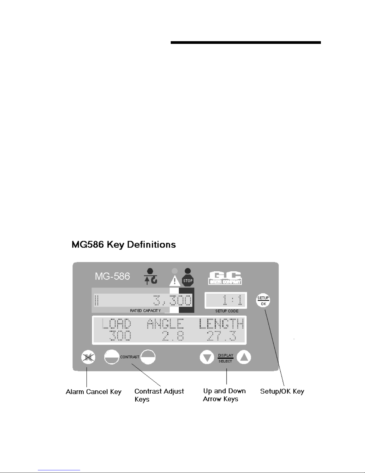
MicroGuard® 586 Key Definitions .................................................................................... 3
Preliminary Checks ......................................................................................................... 4
Boom Hoist Geometry..................................................................................................... 4
Miscellaneous Data......................................................................................................... 5
Installation Checks
..................................................................................................................................
Calibration Routines and Menu Entry.............................................................................. 6
00 Information ................................................................................................................. 6
01 Reset Data ................................................................................................................. 7
6
02 Dimensions ................................................................................................................ 7
03 Zero Angle Sensor ..................................................................................................... 8
04 Zero Extension Sensor............................................................................................... 8
05 Pressure.....................................................................................................................8
06 Radius/Moment ....................................................................................................... 8-9
07 Deflection .............................................................................................................. 9-10
08 Calibrate Fly ............................................................................................................. 10
09 Stowed Jibs.............................................................................................................. 11
10 Digital Input .............................................................................................................. 11
11 Angle Rate ............................................................................................................... 11
Worksheets .............................................................................................................. 12-21
GREER COMPANY 1918 E. Glenwood Place, Santa Ana, CA 92705 Telephone: (714) 259-9702 Fax: (714) 259-7626
MicroGuard
®
586 Retrofit Calibration Manual
PN W458199 Rev A 09/27/02
GREER COMPANY Page 3 of 22
Crane Systems
Introduction
Congratulations on purchasing the new MicroGuard® 586 Retrofit System.
This document describes the calibration process for the MicroGuard
assuming that there is no prior knowledge of the geometry of the crane.
This document is designed to assist the calibration personnel in keeping a record of measured
dimensions and test results for review and comparison when subsequent modifications are made to the
capacity chip. This data will provide an on-file record, which may serve future upgrades and changes to
MicroGuard
Recording this important data during the calibration process will ensure a structured and easy to follow
calibration that in turn leads to an accurate and safe calibration.
®
designs.
®
586 System in an onsite situation,
Notice
This document and resulting data about the crane are confidential.
Copies of this document may not be distributed to third parties in any
form without the prior written consent of the Greer Company and the
crane manufacturer.
Tools Required
Digital Volt/Ohmmeter
Inclinometer – accurate to 0.1°
Measuring tape
Hand tools
The above keys will be referred to many times in the following procedures. The “UP” and “DOWN” arrow
keys are used to select from menus and to increase or decrease numeric values on the display.
The “SETUP/OK” key is usually used to enter a finished number or enter a function via a menu.
The “ALARM CANCEL” key is often used to exit a routine.
GREER COMPANY 1918 E. Glenwood Place, Santa Ana, CA 92705 Telephone: (714) 259-9702 Fax: (714) 259-7626
MicroGuard
®
586 Retrofit Calibration Manual
PN W458199 Rev A 09/27/02

GREER COMPANY Page 4 of 22
Crane Systems
Preliminary Checks
Before starting calibration, it is important to check the machine geometry. Geometric values may have
been previously entered into the capacity chip from the crane application data sheet filled out by the
crane manufacturer’s engineering department. This data will appear in the relevant boxes, but should
STILL be checked by the calibration personnel.
The following pages provide a list of required measurement checks. Measured values should be entered
in the spaces provided.
Using an accurate tape, measure each dimension shown. It is, at best, a difficult exercise to measure
these dimensions, but still a necessary check. It is recommended that two people carry out this task.
Ensure that clear reference points are used when making measurements.
Boom Hoist Geometry
Dimension “L” is the distance parallel to the boom centerline between the center of the Boom pivot and
the center of the upper Boom Hoist cylinder pivot.
Dimension “J” is the distance at 90 ° to the boom centerline between the center of the Boom pivot and
the center of the upper Boom Hoist cylinder pivot. J is negative when the Boom pivot is above the upper
Boom Hoist cylinder pivot and positive when it is below.
Dimension “G” is the horizontal distance between the center of the Boom pivot and the center of the
lower Boom Hoist cylinder pivot.
Dimension “H” is the vertical distance between the center of the Boom pivot and the center of the lower
Boom Hoist pivot.
It is recommended that the boom is level when measuring dimensions “L” and “J.”
The carrier is assumed to be level for the purposes of measuring dimensions “G” and “H.”
Enter the measured values into each of the gray boxes provided below.
L
Boom Pivot
Boom
J
H
Upper Pivot
G
Lower Pivot
Boom Hoist Cylinder
*
*
If the Boom pivot is above the Boom Hoist cylinder Upper pivot (as shown), dimension “J” is negative.
Clearly indicate “+” or “-”. The above illustration shows dimension “J” as negative.
GREER COMPANY 1918 E. Glenwood Place, Santa Ana, CA 92705 Telephone: (714) 259-9702 Fax: (714) 259-7626
MicroGuard
®
586 Retrofit Calibration Manual
PN W458199 Rev A 09/27/02
GREER COMPANY Page 5 of 22
Crane Systems
Miscellaneous Data
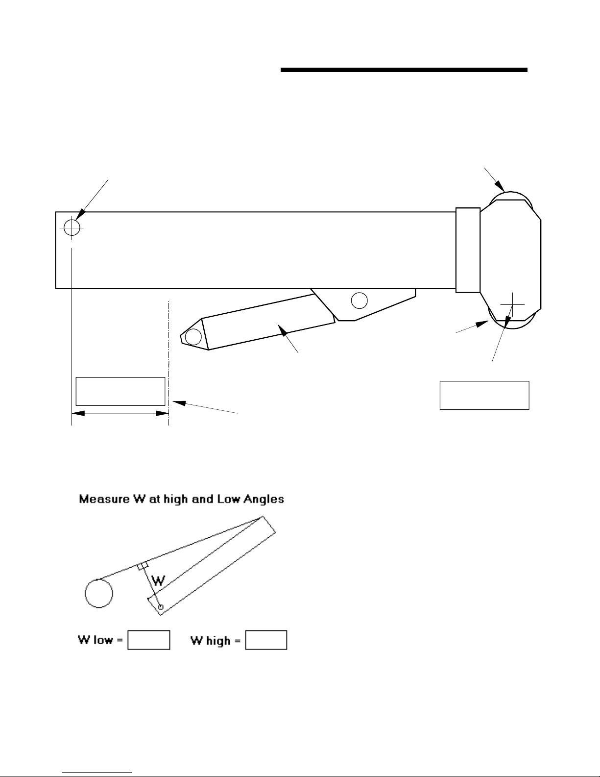
The following checks are for Main Boom Head Sheave Radius and Swing Offset. Swing Offset
is negative when the boom pivot is behind the center of rotation. Measure the circumference of the
boom hoist cylinder rod, which can be done by wrapping a tape around the rod and reading off the value.
Enter the measured values in the gray boxes provided.
Top Sheave
Boom Pivot
Boom
Head Sheave
Boom Hoist Cylinder
Hd Shv radius
Center of Rotation
Swing Offset
Measure the W Dimensions on Non Boom-Mounted Hoist Reels.
Measure “W” at a low angle < 20 ° and at a high angle > 60 °. ‘W’ is the shortest
distance from the boom pivot to the hoist rope.
GREER COMPANY 1918 E. Glenwood Place, Santa Ana, CA 92705 Telephone: (714) 259-9702 Fax: (714) 259-7626
MicroGuard
®
586 Retrofit Calibration Manual
PN W458199 Rev A 09/27/02

GREER COMPANY Page 6 of 22
Crane Systems
Installation Checks
Check wiring and EPROM installations.
•
If swing switches are fitted, perform the digital input monitor routine via the MicroGuard® display
•
to ensure that the switches operate correctly.
• Set the Extension Reel Clutch.
Calibration Routines and Menu Entry
The calibration routines, which are hidden from normal use, require the use of the entry code supplied
with this manual.
To Enter the Calibration Mode:
about 6 seconds. A message requesting a PIN entry should appear. Use the UP and DOWN keys to
enter the PIN, which is 112; calibration entry is complete. If incorrectly entered, the display will return to
the normal working mode.
Once in the calibration mode, the options below are available. Use the UP or DOWN arrow key to display
the desired option. Then, use the SETUP/OK key to enter the routine.
To exit the calibration menu at any time, press the ALARM CANCEL key; this action will return the system
to the normal working screen. After the initial entry of the PIN, the calibration mode can be re-entered at
any time by holding down the ALARM CANCEL and UP arrow keys. No code entry will be required as
long as the power is not reset.
00 - Information - Displays system information and error codes.
01 - Reset Data - Crane data reset to initialize system before calibrating.
02 - Dimensions - Allows entry of crane geometry.
03 - Angle Sensor - Allows calibration of the angle sensor.
04 - Extension Sensor Allows calibration of the extension sensor.
05 - Pressure - Allows calibration of boom hoist dimensions.
06 - Radius/Moment- Allows calibration of radius and boom moment parameters.
07 - Deflection - Allows entry of a boom bending correction.
08 - Calibrate Fly - Allows calibration of fly/jib dimensions.
09 - Stowed Jibs - Allows entry of stowed jib data.
10 - Digital Input - Allows viewing of digital input status.
11 - Angle Rate - Calibrates dynamic properties of the boom.
12 - Data Viewer - Allows viewing of system variables.
Hold down the ALARM CANCEL key and the UP ARROW key for
00 Information
This routine allows viewing of the system error codes and the crane specific applications file used
in the computer. Use the UP or DOWN arrow keys to move between information displays.
The following information is available:
1. System Error Codes (See Appendix for description).
2. Computer specific serial number (should match the number on the computer box).
3. The crane specific applications file used for system RESET.
4. Suggested diagnostics. These are recommendations on how to finish or improve a calibration.
All calibration functions are not pertinent to all cranes; therefore, some diagnostic suggestions
may not apply.
5. Exit the routine using the ALARM CANCEL key.
GREER COMPANY 1918 E. Glenwood Place, Santa Ana, CA 92705 Telephone: (714) 259-9702 Fax: (714) 259-7626
MicroGuard
®
586 Retrofit Calibration Manual
PN W458199 Rev A 09/27/02

GREER COMPANY Page 7 of 22
Crane Systems
01 Reset Data
“Reset Data” from the calibration menu will display the status of the “Personality.” If the system has been
reset and is functioning correctly, it should say, “Personality is good.”
In order for calibration to begin again, the crane RESET DATA MUST be implemented. This function will
erase the Personality memory, which stores crane specific data and dimensions; it will also copy any
known data from the on-board ROM applications file to the working personality memory for use by the
system.
To reset crane data, simply enter the routine using the SETUP/OK key, then confirm the reset command
be pressing the indicated keys.
02 Dimensions
The dimensions routine will show the current values of the following crane dimensions.
Use the UP or DOWN keys to modify the displayed values. Use the SETUP/OK key to move on and save.
Use the ALARM CANCEL key to exit this routine.
Procedure:
1. Enter Swing Offset - Enter value from above worksheet.
2. Enter Ram L - Enter value from above worksheet.
3. Enter Ram J - Enter value from above worksheet.
4. Enter Ram G - Enter value from above worksheet.
5. Enter Ram H - Enter value from above worksheet.
6. The system will now ask,
Y/N caption to make a selection.
“Is the winch mounted on the boom?”
Press the button under the
• If “YES,” the system will require no more information regarding the crane winch.
• If “NO,” the system will ask,
calibrated, press “YES” and work through the following calibration procedure. If previously
calibrated, press “No” to continue.
Calibrating the Hoist Rope
a. Follow the instructions provided on the screen, instructing the operator to move the boom to a
high and low angle while fully telescoped in.
b. Measure the shortest distance from the boom pivot to the hoist rope. This can be done by
placing one end of the tape on the pivot and arcing the tape to find the shortest distance.
c. The dimensions entered are “High Angle W” and “Low Angle W.” (See above worksheet on
measuring W dimensions on non boom-mounted hoist reels.)
Continue with steps 7-13 below.
7. Head Shv. Rad - Enter value from above worksheet.
8. Enter RopeLim - Maximum line pull for a single part of line.
9. Enter Max POL - Maximum parts of line allowed on the main boom.
10. Enter Max Ext - Maximum boom extension allowed.
11. Load Scale - A load multiplier, usually set to 1.0.
12. Length Offset - Display offset added to length (gets over some OEM cheats).
13. Retracted Length - Retracted length of boom. (Measure it!)
“Calibrate Hoist Rope Dimensions?”
Unless previously
GREER COMPANY 1918 E. Glenwood Place, Santa Ana, CA 92705 Telephone: (714) 259-9702 Fax: (714) 259-7626
MicroGuard
®
586 Retrofit Calibration Manual
PN W458199 Rev A 09/27/02
 Loading...