

2000PSI Pressure Washer
EPW-2000
Owner’s Manual
TOLL-FREE HELPLINE: 1-833-493-5483
www.greenworkselite.com
Read all safety rules and instructions carefully before operating this tool.

CONTENTS
Contents .............................................................................................................................. 2
Product Specications ......................................................................................................... 2
Important Safety Information ............................................................................................... 3
Symbols ............................................................................................................................... 6
Electrical .............................................................................................................................. 8
Know Your Pressure Washer ............................................................................................... 9
Assembly Instruction ......................................................................................................... 10
Operation Instruction ......................................................................................................... 16
Maintenance ...................................................................................................................... 22
Troubleshooting ................................................................................................................. 24
Limited Warranty ................................................................................................................ 25
Exploded View ................................................................................................................... 26
Parts List............................................................................................................................ 27
PRODUCT SPECIFICATIONS
HIGH PRESSURE WASHER
Model ..............................................................................................................EPW-2000
Universal Motor ..........................................................................120 V~ 60 Hz, 14 Amps
Max. Pounds Per Square Inch Pressure ........................................................... 2000 PSI
Rated Gallons Per Minute ................................................................................... 1.2 gpm
Maximum Inlet Water Temperature ..............................................................104°F (40°C)
Cleaning Units ................................................................................................ 2,400 C.U.
Weight..... ..............................................................................................30.9 lbs. ( 14 kg)
1
YEAR/ANS/AN
CHARGER WARRANTY
GARANTIE DE
INSTRUMENT
GARANTIE DU
CHARGEUR
2

IMPORTANT SAFETY INSTRUCTIONS
WARNING
Read and understand all instructions. Failure to follow all instructions listed below may
result in electric shock, re, and/or serious personal injury.
WARNING
When using this product, basic precautions should always be followed.
READ ALL INSTRUCTIONS BEFORE USING THIS PRODUCT
• To reduce the risk of injury, close supervision is necessary when a product is used near
children.
• Be thoroughly familiar with controls. Know how to stop the product and release pressure
quickly.
• Stay alert and exercise control. Watch what you are doing and use common sense. Do not
operate the product when you are tired. Do not rush.
• Do not operate the product while under the inuence of drugs, alcohol, or any medication.
• Keep the area of operation clear of all people, particularly small children, and pets.
• Don’t overreach or stand on unstable support. Keep proper footing and balance at all times.
• Follow the maintenance instructions specied in this manual.
WARNING
Risk of injection or injury – Do not direct discharge stream at people or animals.
EXTENSION CORDS
• When using a power tool at a considerable distance from a power source, be sure to use
an extension cord that has the capacity to handle the current the product will draw. An
undersized cord will cause a drop in line voltage, possibly resulting in
of power, and/or damage to circuit breaker.
wire size required in an extension cord. Only round jacketed cords listed by Underwriter’s
Laboratories (UL) should be used. When working outdoors with a product, use an extension
cord that is designed for outside use. This type of cord is designated with “WA” or “W” on
the cord’s jacket. Before using any extension cord, inspect it for loose or exposed wires and
cut or worn insulation. It is possible to tie the extension cord and power cord in a knot to
prevent them from becoming disconnected during use. Make a knot, then connect the plug
end of the power cord into the receptacle end of the extension cord. This method can also
be used to tie two extension cords together.
Use the chart to determine the minimum
overheating, loss
WARNING
To reduce the risk of electrocution, keep all connections dry and off the ground. Do not touch
plug with wet hands.
WARNING
Check extension cords before each use. If damaged, replace immediately. Never use the product
with a damaged cord since touching the damaged area could cause electrical shock, resulting in
serious injury.
WARNING
Keep the extension cord clear of the working area. Position the cord so that it will not get caught
on lumber, tools, or other obstructions while you are working with a power tool. Failure to do so
can result in serious personal injury.
3

IMPORTANT SAFETY INSTRUCTIONS
• Know your product. Read the operator’s manual carefully. Learn the machine’s applications
and limitations, as well as the specic potential hazards related to this product.
• To reduce the risk of injury, keep children and visitors away. All visitors should wear safety
glasses and be kept a safe distance from the work area.
• Use the right product for the job. Don’t force the product or the attachments to do a job it was
not designed for. Don’t use it for a purpose not intended.
• Dress properly. Do not wear loose clothing, gloves, neckties, or jewelry. They can get caught
and draw you into moving parts. Rubber gloves and nonskid footwear are recommended
when working outdoors. Also wear protective hair covering to contain long hair.
• Do not operate the equipment while barefoot or when wearing sandals or similar lightweight
footwear. Wear protective footwear that will protect your feet and improve your footing on
slippery surfaces.
• Exercise caution to avoid slipping or falling.
• Always wear eye protection with side shields marked to comply with ANSI Z87.1. Following
this rule will reduce the risk of serious personal injury.
• Use only recommended accessories. The use of improper accessories may cause risk of
injury.
• Check damaged parts. Before further use of the product, all parts should be carefully checked
to determine that they will operate properly and perform their intended function. Check for
alignment of moving parts, binding of moving parts, breakage of parts, mounting, and any
other conditions that may affect its operation. A guard or other part that is damaged must be
properly repaired or replaced by an authorized service center to avoid risk of personal injury.
• Never leave product running unattended. Turn power off. Do not leave the product until it
comes to a complete stop.
• Keep the motor free of grass, leaves, or grease to reduce the chance of a re hazard.
• Follow manufacturer’s recommendations for safe loading, unloading, transport, and storage of
machine.
• Keep product dry, clean, and free from oil and grease. Always use a clean cloth when
cleaning. Never use brake fluids, gasoline, petroleum-based products, or any solvents to
clean product.
• Check the work area before each use. Remove all objects such as rocks, broken glass, nails,
wire, or string which can be thrown by the machine.
• Do not use product if switch does not turn it off. Have defective switches replaced by an
authorized service center.
• Avoid dangerous environment. Don’t expose to rain. Keep work area well lit.
• Do not abuse the cord. Never use the cord to carry the product or to disconnect the plug from
an outlet. Keep cord away from heat, oil, sharp edges, or moving parts. Replace damaged
cords immediately. Damaged cords increase the risk of electric shock.
• Never direct a water stream toward people or pets, or any electrical device.
• Before starting any cleaning operation, close doors and windows. Clear the area to be
cleaned of debris, toys, outdoor furniture, or other objects that could create a hazard.
• Do not use acids, alkalines, solvents, flammable material, bleaches, or industrial grade
solutions in this product. These products can cause physical injuries to the operator and
4

IMPORTANT SAFETY INSTRUCTIONS
irreversible damage to the machine.
WARNING
High pressure jets can be dangerous if subject to misuse.
people, animals, electrical devices, or the machine itself.
• Keep the motor away from ammables and other hazardous materials.
• Check bolts and nuts xing the pressure washer shell for looseness before each use. A loose
bolt or nut may cause serious motor problems.
• Before storing, allow the motor to cool.
• When servicing use only identical replacement parts. Use of any other parts may create a
hazard or cause product damage.
• ONLY use cold water.
• Make sure minimum clearance of 3 feet is maintained from combustible materials.
• Connect pressure washer only to an individual branch circuit.
• Hold the handle and wand securely with both hands. Expect the trigger handle to move when
the trigger is pulled due to reaction forces. Failure to do so could cause loss of control and
injury to yourself and others.
• Save these instructions. Refer to them frequently and use them to instruct other users. If you
loan someone this product, loan them these instructions also.
WARNING(PROPOSITION 65)
Some dust created by power sanding, sawing, grinding, drilling and other construction activities
contains chemicals known to the state of California to cause cancer, birth defects or other
reproductive harm. Some examples of these chemicals are:
• Lead from lead-based paints,
• Crystalline silica from bricks and cement and other masonry products,
• Arsenic and chromium from chemically-treated lumber.
Your risk from these exposures varies depending on how often you do this type of work. To
reduce your exposure to these chemical: work in a well ventilated area, and work with approved
safety equipment, such as those dust masks that are specially designed to lter out microscopic
particles.
The jet must not be directed at
5
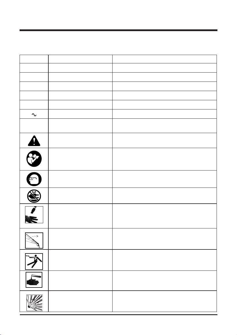
SYMBOLS
Some of the following symbols may be used on this product. Please study them and learn their
meaning. Proper interpretation of these symbols will allow you to operate the product better and
safer.
SYMBOLS DESIGNATION EXPLANATION
V Volts Voltage
A Amperes Current
Hz Hertz Frequency (cycles per second)
W Watts Power
no No Load Speed Rational speed, at no load
Alternating Current Type of current
/min Per Minute
Safety Alert Indicates a potential personal injury hazard.
Revolutions, strokes, surface speed, orbits, etc.,
per minute
Read The Operator’s Manual
Eye Protection
Wet Conditions Alert
Risk of Injection
Kickback
Electric Shock
Chemical Burns
Risk of Explosion
To reduce the risk of injury, user must read and
understand operator’s manual before using this
product.
Always wear eye protection with side shields
marked to comply with ANSI Z87.1.
Do not expose to rain or use in damp locations.
To reduce the risk of injection or injury, never
direct a water system toward people or pets or
place any body part in the stream. Leaking hoses
and ttings are also capable of causing injection
injury. Do not hold hoses or ttings.
To reduce the risk of injury from kickback, hold the
spray wand securely with both hands when the
machine is on.
Failure to use in dry conditions and to observe
safe practices can result in electric shock.
To reduce the risk of injury or damage, DO
NOT USE ACIDS, ALKALINES, BLEACHES,
SOLVENTS, FLAMMABLE MATERIAL, OR
INDUSTRIAL GRADE SOLUTIONS in this product.
Do not spray ammable liquids. Flammable liquids,
fuel, and their vapors are explosive and can cause
severe burns or death.
6
6
SYMBOLS
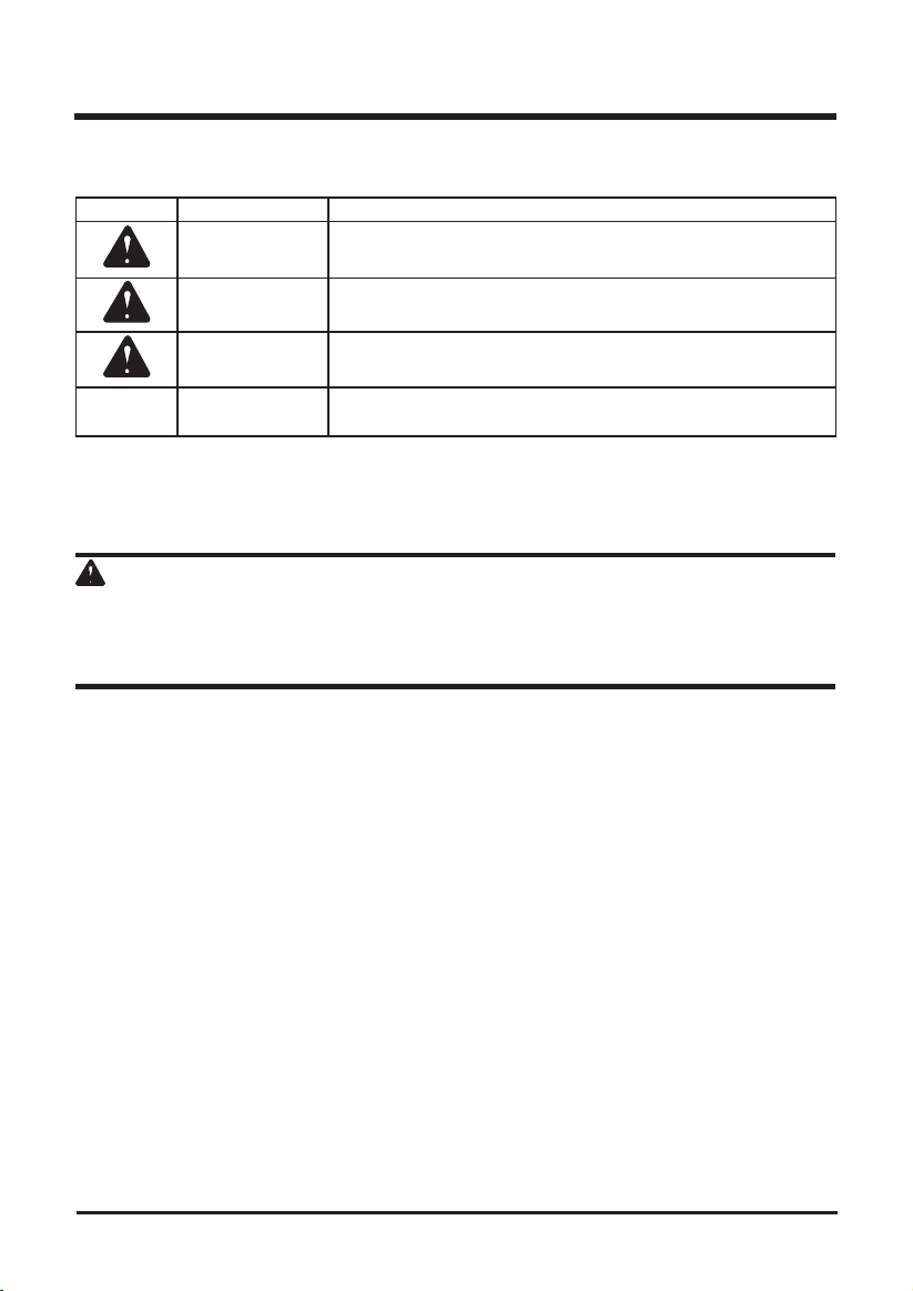
The following signal words and meanings are intended to explain the levels of risk associated
with this product.
SYMBOL SIGNAL MEANING
DANGER
WARNING
CAUTION
CAUTION
SERVICE
Servicing requires extreme care and knowledge and should be performed only by a qualied
service technician. For service we suggest you return the product to your nearest
SERVICE CENTER
for repair. When servicing, use only identical replacement parts.
WARNING
To avoid serious personal injury, do not attempt to use this product until you have read this Owner’s
Manual thoroughly and understand it completely. If you do not understand the warnings and
instructions in this Owner’s Manual, do not use this product. Call the Toll-free Helpline (1-833-493-
5483) for assistance.
Indicates an imminently hazardous situation, which, if not
avoided, will result in death or serious injury.
Indicates a potentially hazardous situation, which, if not avoided,
could result in death or serious injury.
Indicates a potentially hazardous situation, which, if not avoided,
may result in minor or moderate injury.
(Without Safety Alert Symbol) Indicates a situation that may
result in property damage.
AUTHORIZED
SAVE THESE INSTRUCTIONS
7
ELECTRICAL
ELECTRICAL CONNECTION
This product has a precision-built electric motor. It should be connected to a power supply that
is 120 volts, 60 Hz, AC only (normal household current). Do not operate this product on direct
current (DC). A substantial voltage drop will cause a loss of power and the motor will overheat.
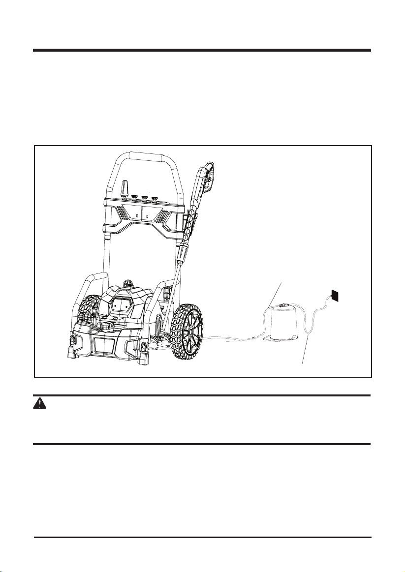
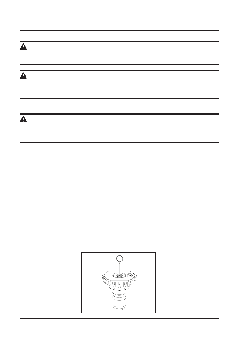
DRIP LOOP
To prevent water from owing along the power cable, and possibly reaching the electrical outlet
and plug, we recommend using a simple drip loop as shown below.
Power cord
Drip Loop
Fig. 1
WARNING
Keep the extension cord clear of the working area. Position the cord so that it will not get caught on
lumber, tools, or other obstructions while you are working with a power tool. Failure to do so can
result in serious personal injury.
8

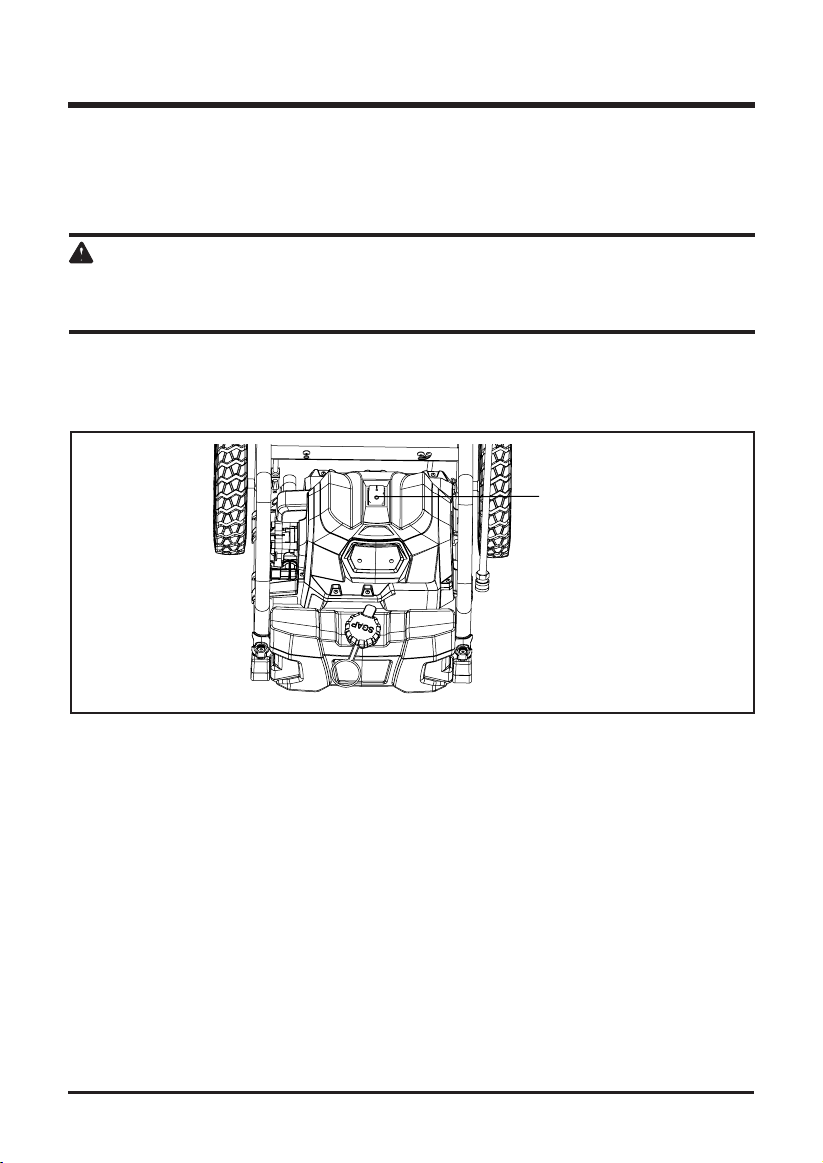
KNOW YOUR PRESSURE WASHER
The safe use of this product requires an understanding of the information on the tool and in this
operator’s manual as well as a knowledge of the project you are attempting. Before use of this
product, familiarize yourself with all operating features and safety rules.(See Figure 2.)
Tip Storage
Trigger and
wand assembl
ON/OFF Switch
Detergent
Tank
Power Cord
Storage
Fig. 2
DETERGENT TANK
Remove the cap from the detergent tank to add detergent to the pressure washer.
GFCI PLUG
The pressure washer power cord is equipped with a GFCI plug to guard against the hazards of
ground fault currents. This plug does not protect against short circuits, overloads, or shocks.
AUTO ON/OFF SWITCH:
This pressure washer is equipped with an Auto Start/Stop feature. To operate: Set power switch
to the On (I) position. Pump will pressurize and shut down immediately. Once the trigger of the
gun is depressed the unit will turn on. Unit will shut off and be in standby mode when trigger is
released.
POWER CORD STORAGE
The power cord can be wrapped and stored around the hook.
TRIGGER AND WAND ASSEMBLY
The Trigger and Wand allows you to operate the pressure washer by depressing the trigger to
activate the pump to spray water using the desired spray tip.
9
ASSEMBLY INSTRUCTIONS
www.GreenWorksTools.com
Rev:02
Connect garden hose to pressure
Once the trigger of the gun is depressed the unit will turn on.
Unit will shut off and be in standby mode when trigger is
released.
This Quick Start Guide is not a substitute for reading the operator's manual. To reduce the risk
of injury or death, user must read and understand operator's manual before using this product.
WARNING:
Set-up
Installing the wheels
Insert the axle through the wheel.
1
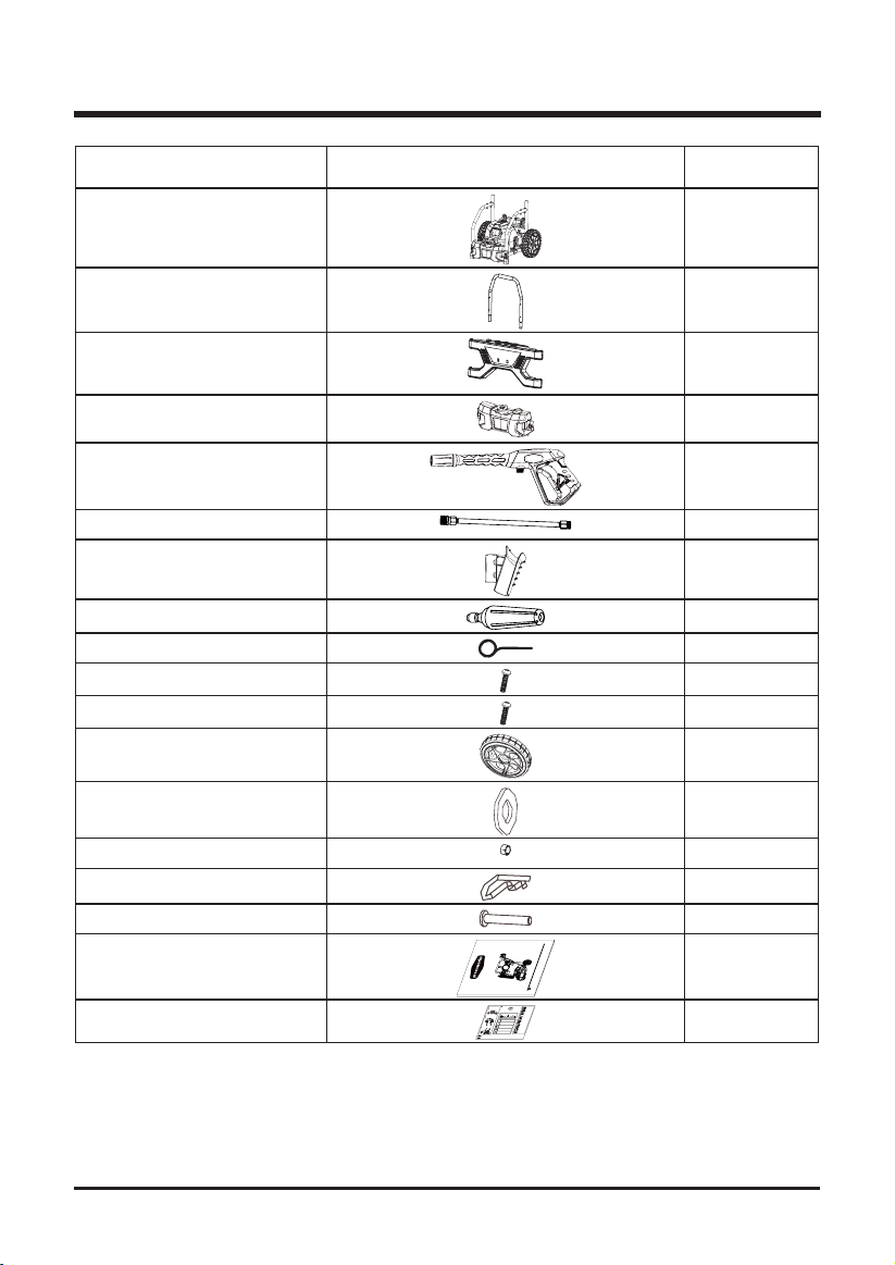
PART NAME FIGURE PART NO.
Pressure Washer 1
Upper Handle
Spray tip panel assy(spray tip
included) 1
Soap tank 1
Trigger Assembly 1
Spray Wand 1
Gun Holder 1
Turbo Nozzle 1
Spray Tip Cleaning Tool 1
Screw 2
Screw 4
Wheels 2
Washer 2
Axle sleeve 2
Pin 2
Axle 2
.
l
o
o
t
)
s
i
7
h
5
t
7
g
6
.
n
i
9
t
0
a
r
9
.
e
8
R
p
8
o
E
8
(
e
r
S
o
f
SH
e
K
L
b
A
R
m
A
y
M
l
o
l
O
W
c
u
P
.
f
s
e
E
l
r
o
ANU
a
R
o
c
t
1 G
00
M
.
s
U
s
8
k
1
n
S
r
o
o
/
i
t
R’
SS
w
c
n
W 1
u
O
E
r
SI
e
t
T
P
e
R
s
r
A
n
P
g
i
P
G
R
d
Operator’s Manual
Quick Start Guide
w.
n
w
IC
a
800
w
s
1
R
OPE
e
l
T
u
r
C
y
t
E
e
f
L
a
s
E
l
l
a
d
LL-FREE HELPLINE: 1-888-90W
a
e
O
R
T
Slide the washer over the axle pass the pin hole.
washer water intake.
Insert the axle and wheel through the frame. Slide the washer
over the axle and insert the pin through the hole to firmly fasten
the wheel assembly.
2
Assemble pressure washer gun to spray wand.
1800 PSI / 1.1 GPM
Wheel
ELECTRIC PRESSURE WASHER
GPW 1800
USING DETERGENT
3
Connect desired pressure tip.
Put pressure washer detergent in detergent tank.
25
Axle
WasherPin
Install blue or black soap nozzle.
Squeeze trigger and wait approx.1 minute for soap.
Installing the gun holder
5
2
Line up the screw sleeves with the holes in the upper handle
and push through.
4
Insert the screw and turn clockwise with a Phillips head
Insert high pressure hose into trigger
screwdriver (not included) until the screw is tight.
handle.
SPRAY TIPSPRAY TIP APPLICATION
Red - Stream tip (0° )
5
Connect the high pressure hose to the
The red 0 degree tip provides a straight line of spray. It provides the highest
O
water outlet connector.
0
amount of pressure. It is best used for removing hard, stuck-on grime or dirt.
Green - Narrow fan tip (25° )
The green pressure washer tip provides high versatility with its 25 degree angle tip.
Referred to as the washing tip, because it provides adequate pressure to remove
O
dirt from surfaces, but is designed to not damage many surfaces. This pressure
6
Turn on water at outlet.
25
washer tip is designed for “sweeping” foliage or debris given its wide angle. This tip
is versatile due to its wide area of cleaning and strong pressure application.
White - Wide fan tip (40° )
Installing the upper handle
The white 40 degree tip, referred to as the “fan” tip creates the widest area of
7
Run water hose for 30 seconds with the
cleaning with relatively low pressure. This pressure washer tip is best used for light
Push and hold the push-pin buttons on the sides of the upper
O
motor in OFF position. This helps drain air
or delicate cleaning applications. It is recommended for light cleaning on wood
handle assembly (1) as you slide the handle onto the frame (2).
40
from the tank and lines.
decks and other soft or delicate surfaces.
S
30
(1)
Black - Soap spray tip
8
Connect power cord to wall outlet
The black soap spray tip, is used for soap application. Soap is applied under low
Extension cord not recommended.
pressure high volume for optimum performance. Soap cannot be applied under
Push-pin
(2)
SOAP
high pressure with this machine.
9
Turbo Nozzle Tip
Turn on Pressure Washer
The nozzle rotates in a zero to 15 degree spray pattern in a circular motion to
IMPORTANT: Ensure water outlet is On
break down tough dirt and grime. The spray pattern can cover area of 4 to 8 inches
before turning power On to avoid damage
wide, depending on a distance between the tip and the surface being cleaned.
to the pump.
NOTE:
AUTO ON/OFF SWITCH: This Pressure washer is equipped
Missing parts, accessories or need a service center?
with an Auto Start/Stop feature.
Do Not Return to Store
To operate: Turn the power switch to the On (I) position.
Call : 1-888-909-6757
Pump will pressurize and shut down immediately.
1
1
1
10
ASSEMBLY INSTRUCTIONS
UNPACKING
This product requires assembly.
• Carefully remove the product and any accessories from the box. Make sure that all the
contents from the packaging list are included.
• Inspect the product carefully to make sure no breakage or damage occurred during shipping.
• Do not discard the packing material until you have carefully inspected and satisfactorily
operated the product.
• If any parts are damaged or missing, please call 1-833-493-5483 for assistance.
WARNING
Do not use this product if any parts on the Packing List are already assembled to your product
when you unpack it. Parts on this list are not assembled to the product by the manufacturer and
require customer installation. Use of a product that may have been improperly assembled could
result in serious personal injury.
WARNING
If any parts are damaged or missing do not operate this product until the parts are replaced. Use
of this product with damaged or missing parts could result in serious personal injury.
WARNING
Do not connect to power supply until assembly is complete. Failure to comply could result in
accidental starting and possible serious personal injury.
WARNING
Do not attempt to modify this product or create accessories not recommended for use with this
product. Any such alteration or modication is misuse and could result in a harzardous condition
leading to possible serious personal injury.
11
ASSEMBLY INSTRUCTIONS
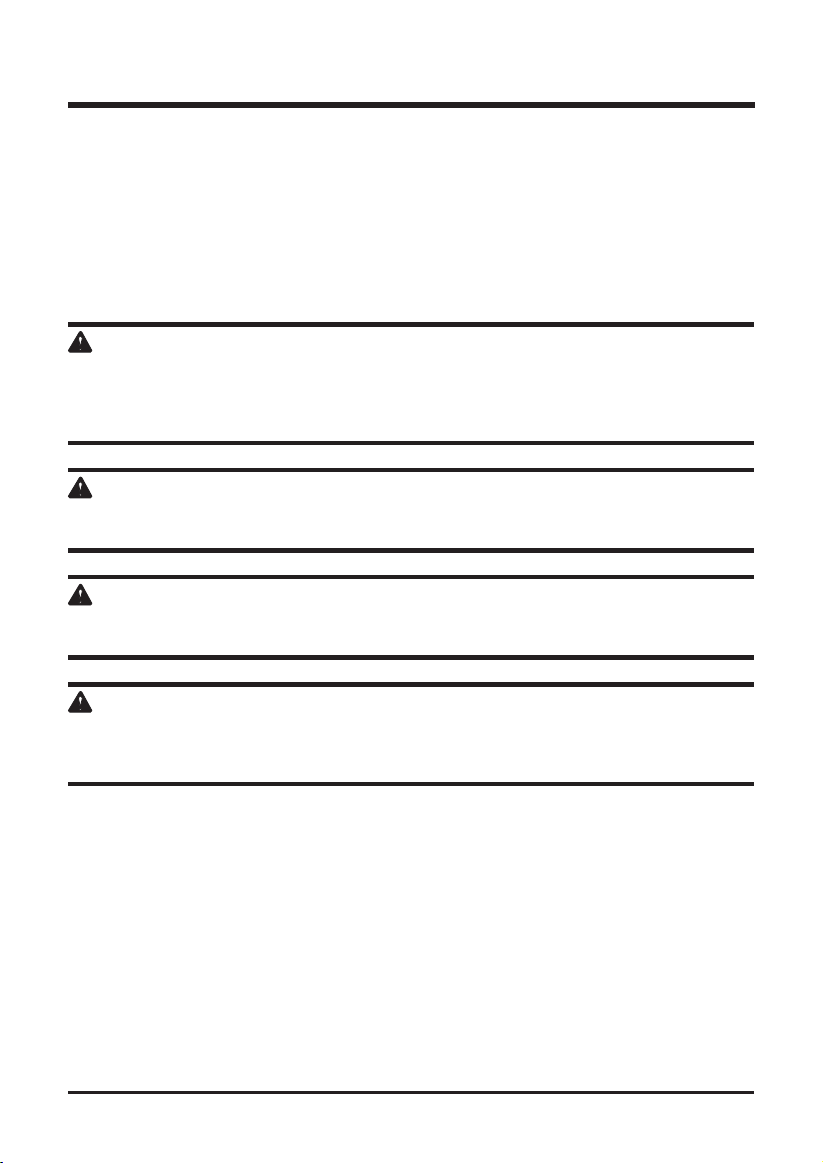
ASSEMBLING THE WHEELS
• Insert an axle (A) through a wheel (I), the axle sleeve (M), the frame of the unit and then a
washer (J).
• Insert a cotter pin (K) through the hole in the axle to secure. Repeat for second wheel.
A
See Figure 3.
A
K
J
M
I
ASSEMBLING THE FRONT PANEL AND GUN HOLDER
• Line up the screw sleeves with the holes in the upper handle and push through.
• Insert the screw and turn clockwise with a phillips head screw driver (not included) until the
screw is tight.
ASSEMBLING THE HOSE HOOK
• Line up the hose hook upper end with the holes on the back of the front panel
• Insert the hose hook end into the hole and push through.
• Press the hose hook lower end into the clip on the back of the front panel.
See Figure 4.
See Figure 4.
Fig. 3
upper end
clip
hole
lower end
Fig. 4
12
ASSEMBLY INSTRUCTIONS
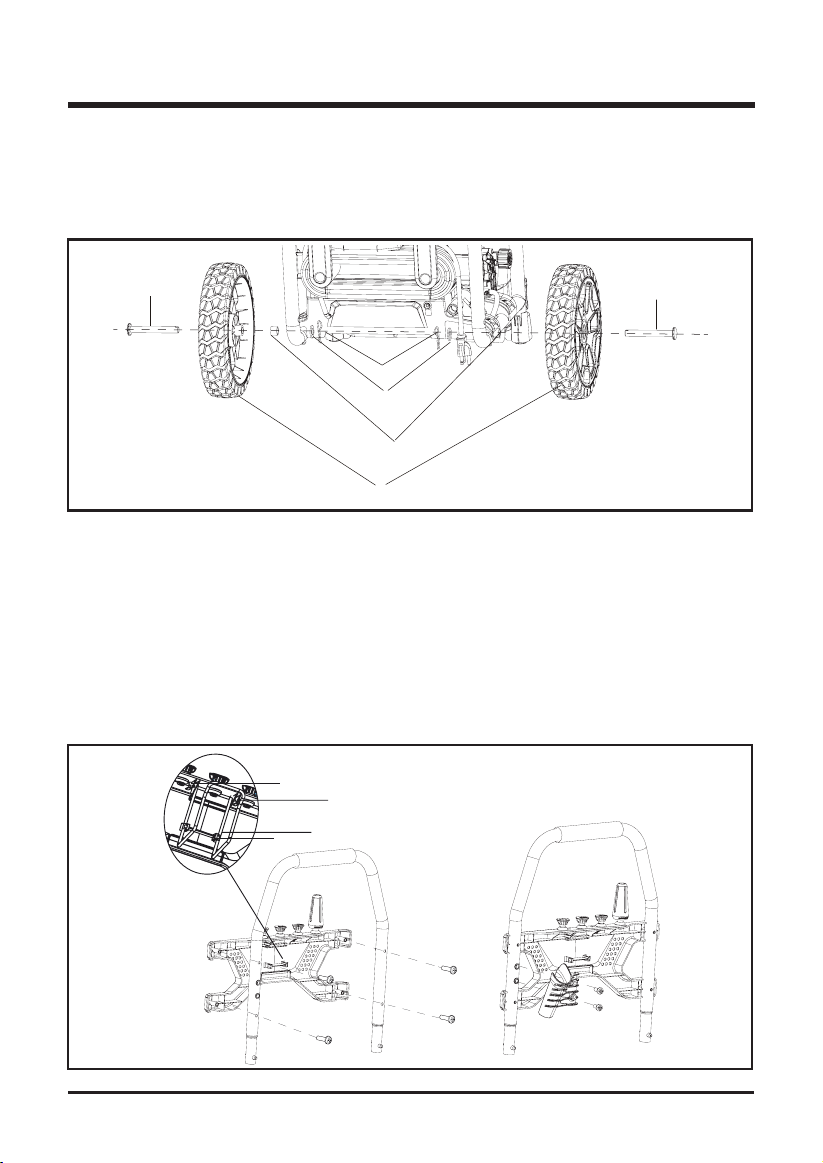
See Figure 5.
INSTALLING THE HANDLE
• Push and hold the button on the handle as you slide the handle into the holes in the frame.
NOTE:
Before use, pull the handle up until the lock button snaps through the locking slot to
secure the handle in place.
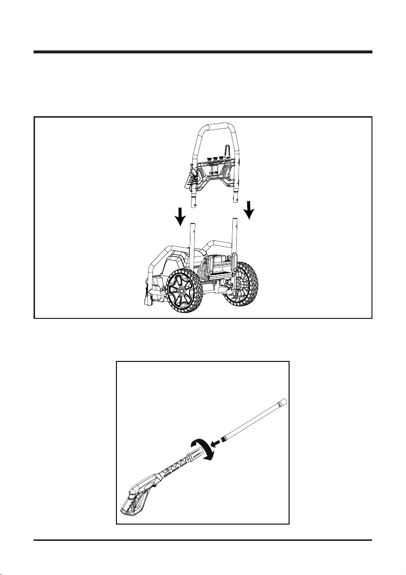
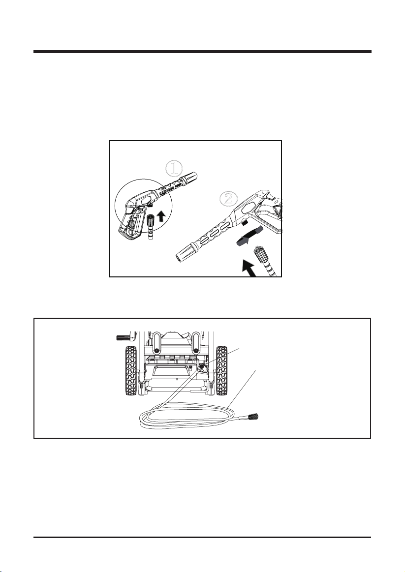
ASSEMBLING THE SPRAY WAND
• Push the end of the spray wand into the trigger handle and rotate clockwise to secure.
• Pull on the spray wand to be certain it is properly secured.
Fig. 5
See Figure 6.
13
Fig. 6
ASSEMBLY INSTRUCTIONS
See Figure 7.
CONNECTING HIGH PRESSURE HOSE TO TRIGGER HANDLE
• Align the pressure hose with the trigger handle and push up and into position.
• With hose pushed into position on the trigger handle, secure in place by turning the hose lock
clockwise until fully tightened.
NOTE:
For easier installation of the hose to the unit or trigger, it is suggested to add pressure
washer or dish detergent to the rubber seal at each end of the hose. This will allow for easier
installation and a snug t.
①
②
Fig. 7
CONNECTING HIGH PRESSURE HOSE TO PRESSURE WASHER
• Connect one end of the hose to the water outlet connector and the other end to the trigger
gun.
See Figure 8.
14
Outlet
Connector
High pressure
L
hose
Fig. 8
ASSEMBLY INSTRUCTIONS
See Figure 9.
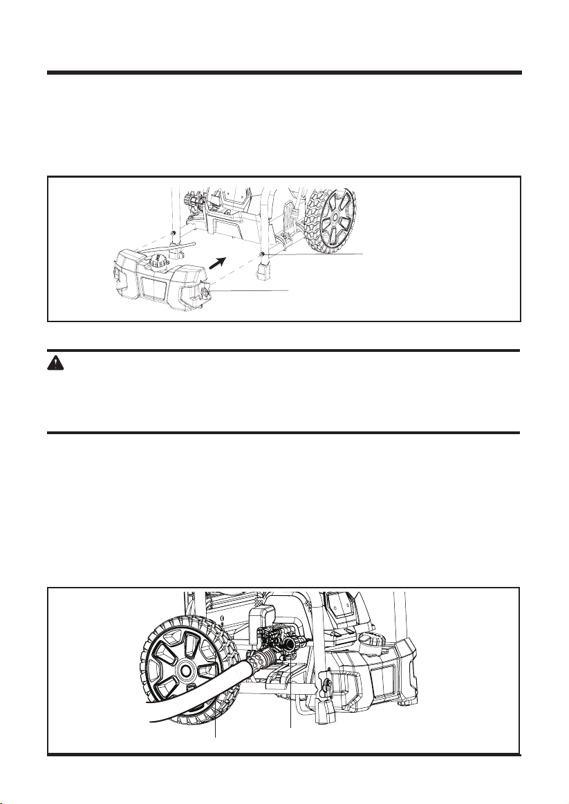
ATTACHING THE SOAP TANK
• Align the keyhole slots with the mounting posts.
• Slide onto mounting posts and push down to hold in place.
• Route the detergent injection hose under the unit and onto the detergent injection hose tting
on the back of the pump as shown.
Mounting post
CONNECTING THE GARDEN HOSE
Key hole
See Figure 10.
Fig. 9
CAUTION
Always observe all local regulations when connecting hoses to the water main. Some areas have
restrictions against connecting directly to public drinking water supply to prevent the feedback of
chemicals into the drinking water supply. Direct connection through a receiver tank or back ow
preventer is usually permitted.
• Uncoil the garden hose.
NOTE:
There must be a minimum of 10 feet of unrestricted garden hose between the water
intake and the garden hose faucet or shut off valve (such as a “ Y” shut off connector).
• Run water through the hose (A) for 30 seconds to clean any debris from the hose.
• Inspect the screen in the water intake (B).
• If the screen is damaged, do not use the machine until the screen has been replaced.
• If the screen is dirty, clean it before connecting the garden hose to the machine.
• With the hose faucet turned completely off, attach the end of the garden hose to the water
intake. Tighten by hand only.
A
B
Fig. 10
15
OPERATION INSTRUCTION
WARNING
Do not allow familiarity with tools to make you careless. Remember that a careless fraction of a
second is sufcient to inict serious injury.
WARNING
Always wear eye protection with side shields marked to comply with ANSI Z87.1. Failure to do so
could result in objects being thrown into your eyes resulting in possible serious injury.
WARNING
Do not use any attachments or accessories not recommended by the manufacturer of this tool.
The use of attachments or accessories not recommended can result in serious personal injury.
WARNING
Never direct a water stream toward people or pets, or any electrical device. Failure to heed this
warning could result in serious injury.
APPLICATIONS
You may use this product for the purposes listed below:
• Cleaning boats, cars, trucks, motorcycles, outdoor furniture, grills, house siding, driveways,
patios and decks.
DETERGENT ADDING AND USE
Use only detergents designed for pressure washers; household detergents, acids, alkalines,
bleaches, solvents, ammable material, or industrial grade solution can damage the pump. Many
detergents may require mixing prior to use. Prepare cleaning solution as instructed on the solution
bottle.
SOAP APPLICATION
Soap is applied under low pressure high volume for optimum performance.
Soap can not be applied under high pressure with this machine.
Soap/detergent can only be applied with this machine when the black (75 degree) soap tip is
installed.
To add detergent:
• Place pressure washer upright on a at surface.
• Remove cap from detergent tank.
• Pour detergent into tank.
• Reinstall cap.
See Figure 11.
16
OPERATION INSTRUCTION
Use Black Soap Tip Only
Detergent
Fig. 11
CAUTION
Use only approved pressure washer cleaners. Do not use bleach, chlorine,or any cleaners
containing acids.
To use:
• Connect low pressure black soap spray tip to the wand connector.
• Squeeze the trigger and the detergent will automatically be mixed with the water and dispensed
from the spray tip.
NOTE:
Use a funnel, if needed, to prevent accidental spilling of the detergent outside the tank.
If any detergent is spilled during the lling process, make sure the unit is cleaned and dried
before proceeding.
STARTING AND STOPPING THE PRESSURE WASHER
See Figure 12.
CAUTION
Do not run the pump without the water supply connected and turned on.
• Connect the garden hose.
• Turn the water supply on, then squeeze the trigger and run water hose with motor in OFF
position until a steady stream of water appears. This helps drain air from tank and lines.
NOTE:
If the pressure washer pulsates and the water stream is intermittent turn the pressure
washer off and continue to bleed air out of the system. Ensure to check that the garden hose is
fully turned on and not kinked.
• After ensuring the On/Off switch is in the OFF ( O ) position, connect the pressure washer
to the power supply.
• Press the reset button on the pressure washer’s plug to make sure the unit is ready for
operation.
17
OPERATION INSTRUCTION
• Press the switch to ON ( I ) position to start the motor.
• To stop the motor, release the trigger and press the switch to OFF( O ) position.
NOTE:
The pressure washer may be on and the system may have pressure even when the
pump and/or motor cannot be heard running. Always use caution around the pressure washer.
CAUTION
Hold the trigger handle securely with both hands. Expect the trigger handle to move when the
trigger is pulled due to reaction forces. Failure to do so could cause loss of control and injury to
yourself and others.
NOTE:
AUTO ON/OFF SWITCH: This pressure washer is equipped with an auto start /stop
feature. To operate: Set the power switch to the On (I) position. Pump will pressurize and shut
down immediately. Once the trigger of the gun is depressed, the unit will turn on. Unit will shut
off and be in standby mode when trigger is released.
ON/OFF Switch
Fig. 12
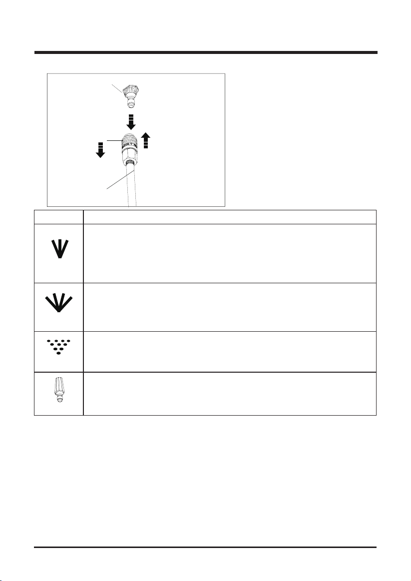
USING THE SPRAY TIPS (See Figure 13)
Each of the spray tips has a different spray pattern. Before starting any cleaning job, determine
the best spray tip for the job. The following chart offers some general guidelines to help you
choose the best spray tip for your application.
NOTE: Always try spray tip in an inconspicuous area rst.
• Turn off the pressure washer and shut off the water supply. Pull trigger to release water
pressure.
• Engage the lock-out on the trigger handle by pushing the trigger lock button to the right.
• Pull out the desired spray tip from the tip storage on the handle.
• Pull back the quick-connect collar on the spray wand.
• Push the spray tip into place in the spray wand.
• Push the collar forward so that the spray tip is secured properly. Check to see that the spray tip
is secure.
NOTE: Make sure the faucet is turned on fully and that there are no kinks or leaks in the hose.
18
OPERATION INSTRUCTION
r
Spray Tip
1
SPRAY TIP
O
25
O
40
SOAP
TURBO
2
3
Spray Wand
Green - Narrow fan tip (25° )
■ The green pressure washer tip provides high versatility with its 25
degree angle tip. Referred to as the washing tip, because it provides
adequate pressure to remove dirt from surfaces, but is designed to
not damage many surfaces. This pressure washer tip is designed for
“sweeping” foliage or debris given its wide angle. This tip is versatile
due to its wide area of cleaning and strong pressure application.
White - Wide fan tip (40° )
■ The white 40 degree tip, referred to as the “fan” tip creates the widest
area of cleaning with relatively low pressure. This pressure washer tip is
best used for light or delicate cleaning applications. It is recommended
for light cleaning on wood decks and other soft or delicate surfaces.
Black - Soap spray tip
■ The black soap spray tip, is used for soap application. Soap is applied
under low pressure high volume for optimum performance. Soap cannot
be applied under high pressure with this machine.
Turbo Nozzle Tip
■ This nozzle rotates in a zero to 15 degree circular motion spray pattern
to break down tough dirt and grime. The spray pattern can cover area of
4 to 8 inches wide, depending on the distance between the tip and the
surface being cleaned.
Fig. 13
APPLICATION
1-Pull back the quick-connect colla
2-Push the spray tip into place
3-Push the collar forward
19
OPERATION INSTRUCTION
WARNING
NEVER change spray tips without engaging the lock-out on the trigger handle and NEVER point
the wand at your face or at others. The quick-connect feature contains small springs that could
eject the spray tip with some force. Failure to heed this may cause personal injury.
TO DISCONNECT A SPRAY TIP FROM THE SPRAY WAND ONCE THE CLEANING
JOB IS COMPLETE:
• Turn off the pressure washer and shut off the water supply. Pull trigger to release water
pressure.
• Remove the spray tip by placing hand over spray then pulling back the quick-connect collar.
Place spray tip in the tip storage area on the units folding handle.
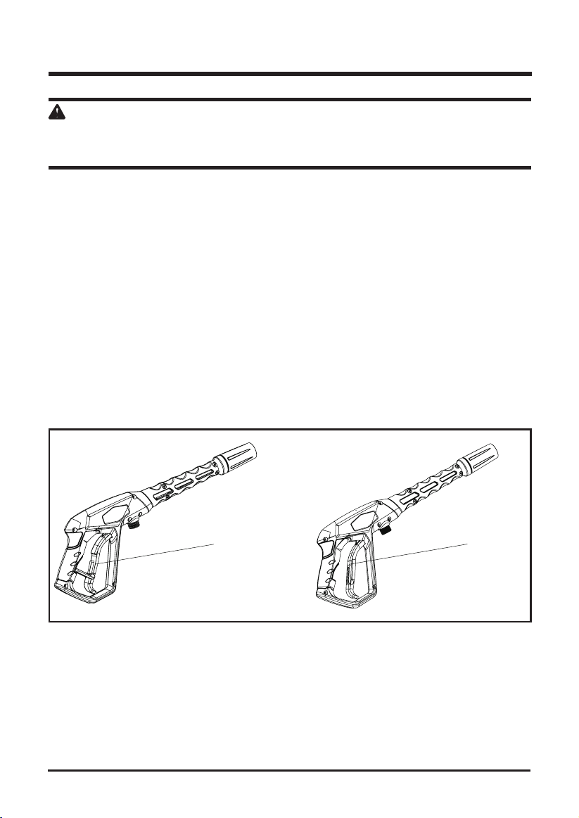
USING THE SPRAY WAND TRIGGER (See Figure 14)
For greater control and safety, keep both hands on the trigger handle at all times.
• Pull back and hold the trigger to operate the pressure washer.
• Release the trigger to stop the ow of water through the tip.
TO ENGAGE THE LOCK-OUT:
• Push the lock-out down until it clicks into the slot.
TO DISENGAGE THE LOCK-OUT:
• Push the lock-out up and into its original position.
Locked
Unlocked
Fig. 14
20
OPERATION INSTRUCTION
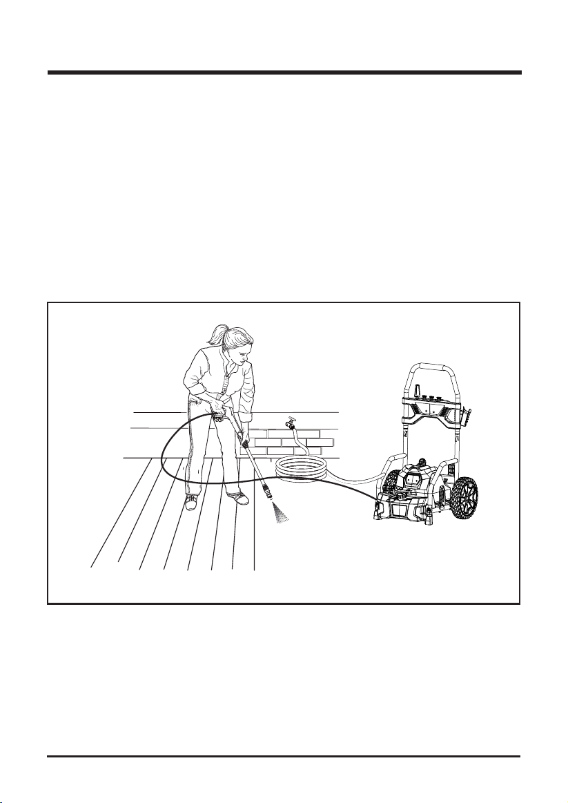
OPERATING THE PRESSURE WASHER (See Figure 15)
Use only detergents designed for pressure washers. Many detergents may require mixing prior to
use. Prepare cleaning solution as instructed on the solution bottle.
a. To clean:
• Pour detergent in the detergent tank.
• Install the black soap tip on the spray wand.
• Start the pressure washer and spray the detergent on a dry surface using long, even,
overlapping strokes. To prevent streaking, do not allow detergent to dry on the surface.
b. To rinse:
• Using the 25° spray tip, spray away from the rinsing surface for approximate 10 seconds to
allow any remaining detergent to be ushed from the line.
• Start at the top of the area to be rinsed and work down, overlapping the strokes.
For the most effective cleaning, the spray tip should be between 8 in. and 24 in. from the surface
to be cleaned. If the spray is too close it can damage the surface.
Fig. 15
MOVING THE PRESSURE WASHER
To move the pressure washer:
• Turn the pressure washer off. Point the spray wand in a safe direction and pull trigger to release
water pressure.
• Tilt the machine toward you until it balances on the wheels, then roll the machine to the desired
position.
21
MAINTENANCE
WARNING
When servicing, use only identical replacement parts. Use of any other parts may create a
hazard or cause product damage.
WARNING
Before inspecting, cleaning or servicing the machine, turn off the unit, unplug from the outlet, pull
trigger to release water pressure and disconnect the high pressure hose. Failure to follow these
instructions can result in serious personal injury or property damage.
GENERAL MAINTENANCE
WARNING
Do not at any time let brake uids, gasoline, petroleum-based products, penetrating oils, etc.,
come in contact with plastic parts. Chemicals can damage, weaken or destroy plastic which may
result in serious personal injury.
Only the parts shown on the parts list are intended to be repaired or replaced by the customer. All
other parts should be replaced at an authorized service center.
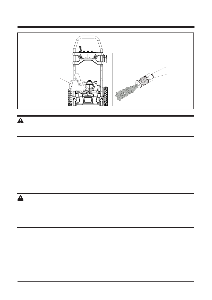
SPRAY TIP MAINTENANCE(See Figure 16)
a. Excessive pump pressure (a pulsing sensation felt while squeezing the trigger) may be the
result of a clogged or dirty spray tip.
• Unplug the pressure washer.
• Turn off the pressure washer and shut off the water supply. Pull trigger to release water
pressure.
• Remove the spray tip from the spray wand.
NOTE: Never point the spray wand at your face.
b. Using the spray tip cleaning tool provided, free any foreign materials clogging or restricting the
spray tip opening.
• Using a garden hose, flush debris out of the spray tip by back flushing (running the water
through the spray tip backwards or from the outside to the inside).
• Reconnect the spray tip to the spray wand.
• Turn on the water supply.
22
Fig. 16

MAINTENANCE
STORING THE PRESSURE WASHER
Store in a dry, covered area where the weather can’t damage it. It is important to store this
product in a frost-free area. Always empty water from all hoses, the pump, and the detergent
container before storing.
NOTE: Use of a pump saver will give you better performance and increase the life of the
machine.
QUICK WINTERIZING PROCEDURE
You can protect your pressure washer from winter damage by doing below:
• Disconnect all water connections.
• Turn on the machine for a few seconds until the remaining water in the pump exits. Turn off
immediately.
• Do not allow high-pressure hose to become kinked.
• Store the machine and accessories in a room that does not reach freezing temperatures. Do
not store near furnace or other sources of heat as it may dry out the pump seals.
CAUTION
Drain gun assembly of any remaining water. Aim gun downwards and squeeze trigger.
SHUTTING DOWN AND CLEANING UP
• (If you are not using detergent, go directly to Step 2.) When you have finished using the
detergent injection system, ll detergent bottle with clean water. Siphon water at low-pressure
for one minute so that all detergent is ushed through system. Remove detergent bottle and
rinse it thoroughly.
• Disconnect the garden hose from the water inlet on the unit.
• Press trigger to release any remaining water pressure.
• Set the switch to “OFF” (O) position.
• Unplug the power cord from the outlet.
• Engage gun safety lock.
TAKING A BREAK
If taking a break of ve minutes or more:
• Engage gun safety lock.
• Set unit to “OFF” (O) position.
• Unplug the power cord from the outlet.
IMPORTANT
The use of a pump protector is recommended when storing to help prevent a against freezing
over the winter months. It also help prevent the seals from drying out while sitting in storage in all
climates.
23

TROUBLESHOOTING
PROBLEM POSSIBLE CAUSE SOLUTION
Motor will not
start.
Unit does not
reach high
pressure.
Output pressure
varies high and
low.
Motor buzzes
but fails to run.
No water.
On/Off switch is in the “OFF”
(O) position.
Power cord is not plugged in. Plug in power cord.
Electrical outlet does not
supply adequate power.
Tripped pressure washer circuit
breaker.
Power switch is ON however gun
trigger is not squeezed ON.
Diameter of garden hose is too
small.
Water supply is restricted.
Not enough water supply. Open water source fully.
Pressure Tip has not been
installed on wand assembly.
Water intake lter is clogged. Remove lter and rinse in warm water.
Not enough inlet water supply.
Pump is sucking air.
Water inlet lter clogged. Remove lter and rinse in warm water.
Supply voltage below
minimum.
Calcied gun, hose or power
spray tip.
Supply voltage below
minimum.
System has residual pressure.
Voltage loss due to extension
cord.
Pressure washer not used for
long periods.
Residual friction among
components. Unit might hum.
Water supply is OFF. Turn ON water supply.
Kink in the garden hose. Remove kink in garden hose.
Set switch to the “ON” ( | ) position.
Try a different outlet.
Allow to cool, and restart unit.
With power switch ON push in on the gun
trigger which will engage the AUTO ON switch.
Replace with a 1” (25 mm) or 5/8” (16 mm)
garden hose.
Check garden hose for kinks, leaks and
blockage.
Add desired pressure tip to end of wand.
Turn water on fully. Check garden hose for
kinks, leaks or blockage.
Check that hoses and ttings are airtight. Turn
“OFF” machine, and purge pump by squeezing
trigger gun until a steady ow of water emerge
through the spray tip.
Verify that only the pressure washer is running
on this circuit.
Run distilled vinegar through detergent tank.
Verify that only the pressure washer is running
on this circuit.
Turn unit “OFF”, squeeze trigger on spray
wand to release pressure, then turn unit “ON”.
Unplug any extension cords attached and plug
the unit directly into the outlet.
Call customer service.
Disconnect water supply and power ON for 2
to 3 seconds, repeat couple times or until the
motor starts.
24

LIMITED WARRANTY
1
YEAR/ANS/AN
CHARGER WARRANTY
GARANTIE DE
INSTRUMENT
GARANTIE DU
CHARGEUR
GREENWORKS ELITE hereby warranties this product, to the original purchaser with
of purchase
GREENWORKS ELITE, at its own discretion will repair or replace any and all parts found to
be defective, through normal use, free of charge to the customer. This warranty is valid only for
units which have been used for personal use that have not been hired or rented for industrial/
commercial use, and that have been maintained in accordance with the instructions in the
owners’ manual supplied with the product from new.
, 1 year consumer warranty against defects in materials, parts or workmanship.
proof
ITEMS NOT COVERED BY WARRANTY:
1. Any part that has become inoperative due to misuse, abuse, neglect, accident, improper
maintenance, or alteration.
2. The unit, if it has not been operated and/or maintained in accordance with the owner's
manual.
3. Normal wear, except as noted below.
4. Routine maintenance items such as lubricating or sharpening.
5. Normal deterioration of the exterior nish due to use or exposure.
GREENWORKS ELITE HELPLINE:
Warranty service is available by calling our toll-free helpline at
1-833-493-5483.
TRANSPORTATION CHARGES:
Transportation charges for the movement of any power equipment unit or attachment are the
responsibility of the purchaser. It is the purchaser’s responsibility to pay transportation charges
for any part submitted for replacement under this warranty unless such return is requested in
writing by
GREENWORKS ELITE
.
25
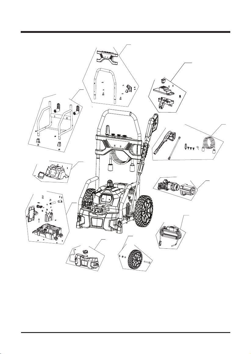
EXPLODED VIEW
2
3
4
5
7
8
10
9
1
6
26

PARTS LIST
NO. PART NO. QTY DESCRIPTION
1 311062584 1 KIT, ACCESSARY
2 311063570 1 KIT, HANDLE
3 311023570 1 KIT, LOWER HOLDER
4 311082583 1 KIT, SWITCH BOX
5 311053570 1 KIT, UPPER HOUSING
6 311112584 1 KIT, MOTOR
7 311073570 1 KIT, LOWER HOUSING
8 364002583 1 KIT, POWER CORD
9 311033570 1 KIT, WHEEL
10 311051823 1 KIT, SOAP TANK
27

TOLL-FREE HELPLINE: 1-833-493-5483
Rev: 00 (01-17-2018)
Greenworks Tools
PO Box 1238
Mooresville, NC 28115

NETTOYEUR HAUTE PRESSION DE
2000 PSI
EPW-2000
Guide d'utilisation
LIGNE D’ASSISTANCE SANS FRAIS: 1-833-493-5483
www.greenworkselite.com
Avant d’utiliser le produit, veuillez lire et suivre toutes les consignes de
sécurité et les instructions d’utilisation.

MATIÈRES
Matières ............................................................................................................................... 2
Fiche technique ................................................................................................................... 2
Instructions importantes concernant la sécurité .................................................................. 3
Symboles ............................................................................................................................. 6
Électricité ............................................................................................................................. 8
Apprendre à connaître le nettoyeur haute pression ............................................................. 9
Instructions pour l’assemblage .......................................................................................... 10
Mode d’emploi .................................................................................................................... 16
Entretien ............................................................................................................................ 23
Dépannage ........................................................................................................................ 25
Garantie limitée ................................................................................................................. 27
Vue éclatée ........................................................................................................................ 28
Liste des pièces ................................................................................................................. 29
FICHE TECHNIQUE
HIGH PRESSURE WASHER
Modèle ............................................................................................................EPW-2000
Moteur universel ......................................................................... 120 V~ 60 Hz, 14 Amps
Pression maximale en livre par pouce carré................................................. 2000 lb/po2
Calibration du débit par minute ........................................................................... 1.2 gpm
Température maximale de l’eau entrante .....................................................104°F (40°C)
Unités de nettoyage ......................................................................................2,400 unités
Poids .................................................................................................... 30.9 lbs. ( 14 kg)
1
YEAR/ANS/AN
CHARGER WARRANTY
GARANTIE DE
INSTRUMENT
GARANTIE DU
CHARGEUR
2

INSTRUCTIONS IMPORTANTES CONCERNANT LA
SÉCURITÉ
AVERTISSEMENT
Assurez-vous de lire et de comprendre toutes les instructions avant d’utiliser cet article.
Le non-respect des instructions ci-dessous peut entraîner une décharge électrique, un
incendie ou des blessures graves.
AVERTISSEMENT
Lorsque vous utilisez ce produit, respectez les mesures de sécurité élémentaires suivantes.
LISEZ TOUTES LES INSTRUCTIONS AVANT D’UTILISER CE PRODUIT
• An de réduire les risques de blessure, une surveillance étroite est de rigueur lorsqu’un
appareil est utilisé à proximité d’un enfant.
• Assurez-vous de bien connaître les commandes. Sachez comment arrêter l’appareil et
évacuez la pression rapidement.
• Restez vigilant et faites preuve de maîtrise. Prêtez attention à ce que vous faites et faites
preuve de bon sens. N’utilisez pas l’appareil lorsque vous êtes fatigué. Ne vous pressez pas.
• N’utilisez pas l’appareil lorsque vous êtes sous l’effet de drogues, d’alcool ou de
médicaments.
• Assurez-vous de garder toutes les personnes, en particulier les jeunes enfants, et les
animaux à l’extérieur de la zone d’utilisation.
• Ne vous étirez pas pour étendre votre portée et n’essayez pas de vous tenir sur une surface
instable. Gardez une posture sécuritaire et un bon équilibre en tout temps.
• Suivez les directives d’entretien de ce manuel.
AVERTISSEMENT
Risque d’injection ou de blessure – ne dirigez pas le jet de sortie vers des personnes ou des
animaux.
RALLONGES
• Lorsque vous devez travailler à une grande distance de la source d’alimentation, utilisez une rallonge qui a la capacité de gérer le courant tiré par le produit. Une rallonge de
calibre insufsant causera une baisse de la tension secteur, ce qui peut provoquer une
surchauffe, une perte de puissance et des dommages au disjoncteur. Utilisez le tableau
ci-dessous pour déterminer le calibre minimum nécessaire pour la rallonge. Seuls les cordons à gaine ronde se trouvant dans la liste des Underwriter’s Laboratories (UL) doivent
être utilisés. Lorsque vous utilisez l’article à l’extérieur, servez-vous d’une rallonge conçue
pour être utilisée à l’extérieur. La gaine de ces types de rallonges est marquée des sigles
« WA » ou « W ». Avant d’utiliser une rallonge, vériezla pour vous assurer qu’elle ne
comporte pas de ls lâches ou dénudés et pour conrmer le bon état de l’isolation (sans
coupure ni signe d’usure). Il est possible de nouer la rallonge et le cordon d’alimentation
ensemble an d’éviter qu’ils ne se débranchent quand vous utilisez le produit. Faites un
noeud, puis branchez la che du cordon d’alimentation sur la prise de la rallonge. Il est
également possible d’employer cette méthode pour nouer deux rallonges ensemble.
AVERTISSEMENT
An de réduire les risques d’électrocution, gardez le cordon d’alimentation dans un
endroit sec, audessus sol. Ne touchez pas à la che avec les mains mouillées.
AVERTISSEMENT
Vérifiez la rallonge électrique avant chaque utilisation. Si elle est endommagée, remplacez-
la immédiatement. N'utilisez jamais le produit avec un câble endommagé car toucher la zone
endommagée peut provoquer un choc électrique et entraîner des blessures graves.
3

INSTRUCTIONS IMPORTANTES CONCERNANT LA
SÉCURITÉ
AVERTISSEMENT
Gardez la rallonge à l’écart de la zone de travail. Disposez-la de façon à ce qu’elle ne s’accroche
pas à des pièces de bois, à des outils ou à d’autres obstacles pendant que vous utilisez l’outil
électrique. Sinon, vous risquez de subir de graves blessures.
• Connaissez bien votre produit. Lisez attentivement le guide d’utilisation. Assurez-vous de
connaître le fonctionnement et les restrictions de la machine ainsi que les dangers potentiels
liés à son utilisation.
• An de réduire les risques de blessure, gardez les enfants et les autres personnes à l’écart.
Tous les visiteurs doivent porter des lunettes de sécurité et se tenir à une distance sécuritaire
de l’aire de travail.
• Utilisez l’outil convenant à votre tâche. Ne tentez pas d’utiliser un outil ou l’un de ses
accessoires pour effectuer un travail pour lequel il n’est pas conçu. N’utilisez pas le produit
pour un usage autre que celui auquel il est destiné.
• Habillez-vous convenablement. Ne portez pas de vêtements amples, de gants, de cravate ou
de bijoux. Ces articles pourraient se coincer dans les pièces en mouvement. Le port de gants
de caoutchouc et de chaussures antidérapantes est recommandé lorsque vous travaillez à
l’extérieur. Couvrez également vos cheveux s’ils sont longs.
• N’utilisez pas l’appareil lorsque vous êtes pieds nus ou lorsque vous portez des sandales ou
d’autres chaussures légères. Portez des chaussures de protection qui protégeront vos pieds
et qui amélioreront votre adhérence sur les surfaces glissantes.
• Faites preuve de prudence pour éviter de glisser ou de tomber.
• Portez toujours des lunettes de sécurité pourvues d’écrans latéraux, conformes à la norme
ANSI Z87.1. En suivant cette règle, vous réduirez les risques de blessures graves.
• Utilisez uniquement les accessoires recommandés. L’utilisation d’accessoires inappropriés
pourrait entraîner des blessures.
• Vérifiez si des pièces sont endommagées. Avant de poursuivre l’utilisation du produit,
inspectez attentivement toutes les pièces an de déterminer s’il fonctionnera correctement
et accomplira sa tâche. Vérifiez si les pièces mobiles sont désalignées ou bloquées, si
les pièces sont brisées ou mal montées ou si elles sont dans un état pouvant nuire à leur
fonctionnement. Si une pièce comme un protecteur ou toute autre pièce est endommagée,
elle doit être réparée ou remplacée par un centre de service autorisé pour éviter les risques
de blessure.
• Ne laissez jamais le produit en marche sans supervision. Coupez l’alimentation électrique. Ne
vous éloignez pas du produit tant qu’il ne s’est pas complètement arrêté.
• Gardez le moteur exempt d’herbe, de feuilles ou de graisse afin de réduire les risques
d’incendie.
• Suivez les recommandations du fabricant pour un chargement, un déchargement, un
transport et un stockage sécuritaires de la machine.
• Gardez le produit sec, propre et exempt d’huile et de graisse. Utilisez toujours un linge propre
pour le nettoyage. N’utilisez jamais de liquide de frein, d’essence, de produits à base de
pétrole ou de solvants forts pour nettoyer le produit.
• Examinez la zone de travail avant chaque utilisation. Enlevez tous les objets qui pourraient
être projetés par l’appareil ou y rester coincés, comme les cailloux, les éclats de verre, les
clous, les câbles ou les ls.
• N’utilisez pas le produit si l’interrupteur ne fonctionne pas. Les interrupteurs défectueux sont
remplacés par un centre de service autorisé.
• Évitez les environnements dangereux. N’exposez pas l’article à la pluie. Gardez l’aire de
travail bien éclairée.
4

INSTRUCTIONS IMPORTANTES CONCERNANT LA
SÉCURITÉ
• N’utilisez pas le cordon d’alimentation de façon abusive. Ne transportez jamais un outil
électrique en le tenant par son cordon, et ne tirez jamais sur le cordon pour débrancher la
che. Tenez le cordon d’alimentation éloigné des sources de chaleur, de l’huile, des objets
coupants et des pièces mobiles. Remplacez immédiatement les cordons endommagés.
Les risques de choc électrique doivent être plus élevés si le cordon d’alimentation est
endommagé.
• Ne dirigez jamais le jet d’eau vers une personne, un animal ou un appareil électrique.
• Avant de commencer toute opération de nettoyage, fermez les portes et les fenêtres.
Dégagez l’aire à nettoyer de tout débris, jouet, meuble d’extérieur ou autre objet susceptibles
de poser des risques.
• N’utilisez pas d’acides, de produits alcalins, de solvants, de matériaux inammables, d’agent
de blanchiment ou de solutions industrielles dans ce produit. Ces produits peuvent causer
des blessures physiques à l’opérateur et des dommages irréversibles à la machine.
AVERTISSEMENT
Les jets à haute pression peuvent être dangereux s’ils sont mal utilisés. Le jet ne doit pas
être orienté vers les gens, les animaux, les appareils électriques ni vers l’appareil en tant
que tel.
• Gardez le moteur à l’écart des liquides inammables et des autres matières dangereuses.
• Vérifiez les boulons et les écrous fixant la coquille de la laveuse à pression avant toute
utilisation. Un boulon ou un écrou desserré peut causer de graves problèmes de moteur.
• Laissez le moteur refroidir avant de ranger l’article.
• Lors de l’entretien, utilisez seulement des pièces de rechange identiques aux pièces d’origine.
L’utilisation de toute autre pièce peut endommager l’outil ou être source de danger.
• Utilisez UNIQUEMENT de l’eau froide.
• Assurez un dégagement minimal de 0,91 m de tout matériau combustible.
• Branchez la laveuse à pression uniquement à un circuit de dérivation individuel.
• Tenez la poignée et la baguette de pulvérisation fermement avec vos deux mains.
Attendezvous à un mouvement de la poignée de la gâchette lorsque vous appuyez sur la
gâchette en raison des forces de réaction. Ne pas le faire pourrait entraîner une perte de
contrôle et des blessures pour vous ou d’autres personnes.
• Conservez ces instructions. Consultez-les souvent et utilisez-les pour donner des directives
aux autres utilisateurs. Si vous prêtez ce produit à quelqu’un, remettez-lui également les
présentes instructions.
AVERTISSEMENT(PROPOSITION65)
La poussière créée pendant le ponçage, le sciage, le polissage, le perçage et d’autres activités
liées à la construction peut contenir des produits chimiques entraînant le cancer, ainsi que
des anomalies congénitales et d’autres problèmes liés aux fonctions reproductrices. Voici des
exemples de ces produits chimiques :
• Le plomb provenant de peintures à base de plomb,
• La silice cristalline provenant de la brique, du ciment ou d’autres matériaux de maçonnerie
• L’arsenic et le chrome provenant du bois d’oeuvre traité avec un produit chimique
Les risques liés à l’exposition à ces produits varient en fonction de la fréquence à laquelle vous
effectuez ce type de travaux. An de limiter votre exposition à ces produits chimiques : travaillez
dans un endroit bien ventilé en vous munissant de l’équipement de sécurité approuvé tel que
des masques antipoussières conçus spécialement pour ltrer les particules microscopiques.
5

SYMBOLES
Certains des symboles suivants peuvent figurer sur cet article. Familiarisez-vous avec eux
et apprenez leur signification. En comprenant ces symboles, vous serez en mesure de faire
fonctionner cet article de façon adéquate et sécuritaire.
SYMBOLES DESCRIPTION DÉFINITION
V Volts Tension
A Ampères Courant
Hz Hertz Fréquence (cycles par seconde)
W Watts Alimentation
no Vitesse à vide Vitesse de rotation à vide
Courant alternatif Type de courant
/min Par minute
Alerte de sécurité Indique un risque de blessure.
Tours, coups, battements, vitesse de surface,
orbites, etc., par minute.
Lire le guide d’utilisation
Lunettes de sécurité
Avertissement relatif aux
conditions humides
Recul
Risque d’injection
Choc électrique
Brûlures chimiques
Risque d’explosion
An de réduire les risques de blessure, l’utilisateur
doit lire et comprendre le guide d’utilisation avant
d’utiliser cet article.
Portez toujours des lunettes de sécurité pourvues
d’écrans latéraux, conformes à la norme ANSI Z87.1.
N’exposez pas cet outil à la pluie et évitez de
l’utiliser dans des endroits humides.
Pour réduire le risque d’injection ou de blessure, ne
dirigez jamais le jet d’eau vers une personne, un
animal ou une partie du corps. Les tuyaux et raccords
qui fuient peuvent également provoquer des blessures
d’injection. Ne tenez pas les tuyaux ni les raccords.
Pour réduire le risque de blessures causé par le
recul, tenez la baguette de pulvérisation fermement
à deux mains lorsque la machine est en marche.
L’utilisation dans des conditions humides et
le nonrespect des règles de sécurité peuvent
entraîner un choc électrique.
Pour réduire le risque de blessures ou de dommages,
N’UTILISEZ PAS D’ACIDES, DE PRODUITS
ALCALINS, D’AGENT DE BLANCHIMENT, DE
SOLVANTS, DE MATÉRIAUX INFLAMMABLES OU
DE SOLUTIONS INDUSTRIELLES dans ce produit.
Ne pas vaporiser de liquides inammables.
Liquides inammables, de carburant, et leurs
vapeurs sont explosifs et peuvent entraîner des
brûlures graves ou mortelles.
6
6

SYMBOLES
Les mots indicateurs suivants et leurs signications servent à expliquer les niveaux de risque
associés à cet appareil.
SYMBOLE MOT INDICATEUR SIGNIFICATION
DANGER
AVERTISSEMENT
ATTENTION
ATTENTION
ENTRETIEN
L’entretien exige une grande prudence et de bonnes connaissances et ne devrait être effectué
que par un technicien qualié. Rapportez l’appareil au
plus près de chez vous pour tout travail d’entretien ou de réparation. Lors de l’entretien, utilisez
seulement des pièces de rechange identiques aux pièces d’origine.
AVERTISSEMENT
Pour éviter des blessures graves, ne tentez pas d’utiliser cet article avant d’avoir lu le guide
d’utilisation attentivement et de l’avoir bien compris. Si vous ne comprenez pas les avertissements
et les instructions de ce guide d’utilisation, n’utilisez pas cet article. Appelez le Service à la
clientèle Greenworks pour obtenir de l’aide au 1-833-493-5483.
Indique un danger imminent qui, s’il n’est pas évité, peut
entraîner des blessures graves ou la mort.
Indique une situation potentiellement dangereuse qui,
si elle n’est pas évitée, pourrait entraîner la mort ou des
blessuresgraves.
Indique un danger potentiel qui, s’il n’est pas évité, peut
causer des blessures mineures ou modérément graves.
(Aucun symbole d’alerte de sécurité) Indique une situation qui
pourrait entraîner des dommages matériels.
CENTRE DE SERVICE AUTORISÉ
le
CONSERVEZ CES INSTRUCTIONS
7

ELECTRICAL
BRANCHEMENT ÉLECTRIQUE
Cet article comprend un moteur électrique conçu avec précision. Il devrait être connecté à
une source d’alimentation électrique de 120 V c.a. et de 60 Hz (courant domestique normal).
N’alimentez pas l’articleà partir d’une source de courant continu (c.c.). Une chute de tension
importante entraînera une perte de puissance et une surchauffe du moteur.
BOUCLE D’ÉGOUTTEMENT
Afin d’éviter que de l’eau s’écoule le long du cordon d’alimentation et n’atteigne la prise
électrique et la che, nous recommandons d’utiliser une simple boucle d’égouttement, comme
l’illustre la gure suivante.
CORDON D’ALIMENTATION
BOUCLE D’ÉGOUTTEMENT
Fig. 1
AVERTISSEMENT
Gardez la rallonge à l’écart de la zone de travail. Disposez-la de façon à ce qu’elle ne s’accroche
pas à des pièces de bois, à des outils ou à d’autres obstacles pendant que vous utilisez l’outil
électrique. Sinon, vous risquez de subir de graves blessures.
8

APPRENDRE À CONNAÎTRE LE NETTOYEUR HAUTE
PRESSION
La sécurité d’utilisation de ce produit exige la compréhension des informations apposées sur l’outil
et contenues dans ce manuel d’utilisation, ainsi que la connaissance du travail à exécuter. Avant
d’utiliser ce produit, se familiariser avec toutes ses fonctions et règles de sécurité.(Voir la gure 2.)
CONSEIL DE RANGEM ENT
ASSEMBLAGE DE LA
GÂCHETTE ET DE LA BAGUETTE
INTERRUPTEUR
RÉSERVOIR DE
DÉTERGENT
RANGEMENT
DU CÂBLE
D’A LI MENTAT ION
Fig. 2
RÉSERVOIR À DÉTERGENT
Retirez le bouchon du réservoir à détergent pour ajouter du détergent dans le nettoyeur haute
pression.
PRISE GFCI
Le câble d'alimentation du nettoyeur à pression est équipé d'une prise GFCI pour prévenir les
risques dus à une non conformité du branchement à la terre. Cette prise ne protège pas contre
les courts-circuits, les surcharges ou les chocs.
INTERRUPTEUR AUTOMATIQUE MARCHE/ARRÊT :
Ce nettoyeur à pression est équipé d'une fonction de mise en marche / arrêt automatique.
Fonctionnement : Réglez l'interrupteur d'alimentation en position de marche (I). La pompe se
mettra sous pression et s'éteindra immédiatement. Une fois que la gâchette du pistolet est
enfoncée, l'appareil se met en marche. L'appareil s'éteindra et se mettra en mode de veille
lorsque la gâchette sera relâchée.
RANGEMENT DU CÂBLE D'ALIMENTATION
Pour faciliter le rangement, le câble d'alimentation peut être enroulé et rangé sur le crochet.
ASSEMBLAGE DE LA GÂCHETTE ET DE LA BAGUETTE
La gâchette et la baguette vous permettent de faire fonctionner le nettoyeur haute pression en
appuyant sur la gâchette pour activer la pompe an de vaporiser de l'eau en utilisant l'embout de
pulvérisation désiré.
9

INSTRUCTIONS POUR L’ASSEMBLAGE
www.GreenWorksTools.com
Rev:02
Connect garden hose to pressure
Once the trigger of the gun is depressed the unit will turn on.
Unit will shut off and be in standby mode when trigger is
released.
This Quick Start Guide is not a substitute for reading the operator's manual. To reduce the risk
of injury or death, user must read and understand operator's manual before using this product.
WARNING:
Set-up
Installing the wheels
Insert the axle through the wheel.
1
NOM DES PIÈCES FIGURE QTÉ
Nettoyeur haute pression 1
Poignée supérieure
Assemblage du panneau de
l’embout de pulvérisation (embout
inclus)
Réservoir de savon 1
A s s e m b l a g e d e l a g â c h e t t e 1
lance de pulvérisation 1
Support à pistolet 1
Embout turbo 1
Outil de nettoyage à pointe de
pulvérisation
Vis 2
Vis 4
Roues 2
Rondelle 2
Gaine d’essieu 2
Broche 2
Essieu 2
.
l
o
o
t
)
s
i
7
h
5
t
7
g
6
.
n
i
9
t
0
a
r
9
.
e
8
R
p
8
o
E
8
(
e
r
S
o
f
SH
e
K
L
b
A
R
m
A
y
M
l
o
l
O
W
c
u
P
.
f
s
e
E
l
r
o
ANU
a
R
o
c
t
1 G
00
M
.
s
U
s
8
k
1
n
S
r
o
o
/
i
t
R’
SS
w
c
n
W 1
u
O
E
r
SI
e
t
T
P
e
R
s
r
A
n
P
g
i
P
G
R
d
Manuel d’utilisation
Guide rapide de démarrage
w.
n
w
IC
a
800
w
s
1
R
OPE
e
l
T
u
r
C
y
t
E
e
f
L
a
s
E
l
l
a
d
LL-FREE HELPLINE: 1-888-90W
a
e
O
R
T
Slide the washer over the axle pass the pin hole.
washer water intake.
Insert the axle and wheel through the frame. Slide the washer
over the axle and insert the pin through the hole to firmly fasten
the wheel assembly.
2
Assemble pressure washer gun to spray wand.
1800 PSI / 1.1 GPM
Wheel
ELECTRIC PRESSURE WASHER
GPW 1800
USING DETERGENT
3
Connect desired pressure tip.
Put pressure washer detergent in detergent tank.
25
Axle
WasherPin
Install blue or black soap nozzle.
Squeeze trigger and wait approx.1 minute for soap.
Installing the gun holder
5
2
Line up the screw sleeves with the holes in the upper handle
and push through.
4
Insert the screw and turn clockwise with a Phillips head
Insert high pressure hose into trigger
screwdriver (not included) until the screw is tight.
handle.
SPRAY TIPSPRAY TIP APPLICATION
Red - Stream tip (0° )
5
Connect the high pressure hose to the
The red 0 degree tip provides a straight line of spray. It provides the highest
O
water outlet connector.
0
amount of pressure. It is best used for removing hard, stuck-on grime or dirt.
Green - Narrow fan tip (25° )
The green pressure washer tip provides high versatility with its 25 degree angle tip.
Referred to as the washing tip, because it provides adequate pressure to remove
O
dirt from surfaces, but is designed to not damage many surfaces. This pressure
6
Turn on water at outlet.
25
washer tip is designed for “sweeping” foliage or debris given its wide angle. This tip
is versatile due to its wide area of cleaning and strong pressure application.
White - Wide fan tip (40° )
Installing the upper handle
The white 40 degree tip, referred to as the “fan” tip creates the widest area of
7
Run water hose for 30 seconds with the
cleaning with relatively low pressure. This pressure washer tip is best used for light
Push and hold the push-pin buttons on the sides of the upper
O
motor in OFF position. This helps drain air
or delicate cleaning applications. It is recommended for light cleaning on wood
handle assembly (1) as you slide the handle onto the frame (2).
40
from the tank and lines.
decks and other soft or delicate surfaces.
S
30
(1)
Black - Soap spray tip
8
Connect power cord to wall outlet
The black soap spray tip, is used for soap application. Soap is applied under low
Extension cord not recommended.
pressure high volume for optimum performance. Soap cannot be applied under
Push-pin
(2)
SOAP
high pressure with this machine.
9
Turbo Nozzle Tip
Turn on Pressure Washer
The nozzle rotates in a zero to 15 degree spray pattern in a circular motion to
IMPORTANT: Ensure water outlet is On
break down tough dirt and grime. The spray pattern can cover area of 4 to 8 inches
before turning power On to avoid damage
wide, depending on a distance between the tip and the surface being cleaned.
to the pump.
NOTE:
AUTO ON/OFF SWITCH: This Pressure washer is equipped
Missing parts, accessories or need a service center?
with an Auto Start/Stop feature.
Do Not Return to Store
To operate: Turn the power switch to the On (I) position.
Call : 1-888-909-6757
Pump will pressurize and shut down immediately.
1
1
1
1
1
10

INSTRUCTIONS POUR L’ASSEMBLAGE
DÉBALLAGE
Cet article est entièrement assemblé avant son expédition.
• Retirez prudemment le produit et les accessoires de la boîte. Assurez-vous que tous les
articles énumérés dans la liste de colisage sont inclus.
• Assurez-vous que le produit n’a pas subi des dommages ou de bris pendant le transport.
• Ne jetez pas le matériel d’emballage avant d’avoir soigneusement inspecté l’outil et de l’avoir
fait fonctionner de manière satisfaisante.
• Si des pièces sont manquantes ou endommagées, veuillez appeler au 1-833-493-5483 pour
obtenir de l’aide.
AVERTISSEMENT
N’utilisez pas ce produit si des pièces gurant sur la liste des pièces contenues dans l’emballage
sont déjà assemblées sur votre produit au moment où vous le déballez. Les pièces figurant
sur cette liste n’ont pas été assemblées au produit par le fabricant et devront être installées
par le client. L’utilisation d’un article qui pourrait avoir été mal assemblé pourrait entraîner des
blessures graves.
AVERTISSEMENT
S’il y a des pièces manquantes ou endommagées, ne tentez pas d’utiliser cet article tant que ces
pièces n’auront pas été remplacées. Le non-respect de cet avertissement pourrait entraîner de
graves blessures.
AVERTISSEMENT
Ne branchez pas l’appareil à une source d’alimentation électrique tant que l’assemblage
n’est pas terminé. Le non-respect de ces consignes pourrait provoquer des mises en marche
accidentelles ainsi que de graves blessures.
AVERTISSEMENT
Ne tentez pas de modier cet article ou de créer des accessoires qui ne sont pas recommandés
pour cet article. Toute modication est considérée comme un usage inapproprié et peut créer
une situation dangereuse susceptible d’entraîner des blessures graves.
11

INSTRUCTIONS POUR L’ASSEMBLAGE
ASSEMBLAGE DES ROUES Voir gure
• Insérez un essieu (A) dans une roue (I), une rondelle (J), le cadre de l’appareil, puis une autre
rondelle (J).
• Insérez une goupille fendue (K) dans le trou de l’essieu pour xer le tout. Faites de même
pour la deuxième roue.
A
3.
A
K
J
M
I
ASSEMBLAGE DU PANNEAU AVANT ET DU PORTE-PISTOLET Voir gure
• Alignez les gaines de vis avec les trous de la poignée supérieure et insérez-les.
• Insérez la vis et tournez-la dans le sens des aiguilles d’une montre avec un tournevis
cruciforme (non inclus) jusqu’à ce que la vis soit bien serrée.
ASSEMBLAGE DU CROCHET DE TUYAU Voir gure
• Alignez l’extrémité supérieure du crochet du tuyau avec les trous à l’arrière du panneau avant
• Insérez l’extrémité du crochet dans le trou et enfoncez-le.
• Enfoncez l’extrémité inférieure du crochet dans le clip situé à l’arrière du panneau avant.
4.
Fig. 3
4.
upper end
clip
hole
lower end
Fig. 4
12

INSTRUCTIONS POUR L’ASSEMBLAGE
ASSEMBLAGE DE LA POIGNÉE Voir gure
• La poussée et tient le bouton sur la poignée comme vous glissez la poignée dans les trous
dans le cadre.
REMARQUE:
poussoirs s’enclenchent dans les fentes de verrouillage. La poignée sera ainsi bien xée en
place.
Avant d’utiliser l’appareil, tirez sur la poignée jusqu’à ce que les boutons-
ASSEMBLAGE DE LA BAGUETTE DE PULVÉRISATION Voir gure
• Poussez le bout de la baguette de pulvérisation dans l’assemblage de la gâchette et tournez
dans le sens des aiguilles d’une montre pour le xer.
• Tirez sur la baguette de pulvérisation pour vous assurer qu’elle est bien xée.
5.
Fig. 5
6.
13
Fig. 6

INSTRUCTIONS POUR L’ASSEMBLAGE
RACCORDEMENT DU TUYAU À HAUTE PRESSION À LA POIGNÉE DE LA
GÂCHETTE Voir gure
• Alignez le tuyau à pression sur la poignée à gâchette, puis appuyez sur le tuyau pour l’insérer
dans la poignée.
• Lorsque le tuyau est bien inséré dans la poignée à gâchette, tournez le dispositif de xation
du tuyau dans le sens des aiguilles d’une montre jusqu’à ce qu’il soit bien serré.
REMARQUE:
d’ajouter un détergent à laveuse à pression ou à vaisselle au joint en caoutchouc de chaque
extrémité du tuyau. L’installation sera ainsi plus facile et assurera un ajustement parfait.
Pour faciliter l’installation du tuyau sur l’unité ou la gâchette, il est conseillé
7.
①
②
Fig. 7
RACCORDEMENT DU TUYAU HAUTE PRESSION AU NETTOYEUR PRESSION Voir gure
• Vissez une extrémité du tuyau au raccord de la sortie d’eau et l’autre extrémité au pistolet.
8.
14
CONNECTEUR DE SORTIE
TUYAU HAUTE PRESSION
L
Fig. 8

INSTRUCTIONS POUR L’ASSEMBLAGE
FIXATION DU RÉSERVOIR DE SAVON Voir gure
• Alignez les fentes en forme de trou de serrure avec les montants de montage.
• Faites glisser les montants de montage et poussez-les pour les maintenir en place.
• Faites passer le tuyau d’injection de détergent sous l’unité et sur le raccord du tuyau d’injection
de détergent à l’arrière de la pompe comme illustré.
Trou de serrure
9.
Montant de montage
Fig. 9
15

INSTRUCTIONS POUR L’ASSEMBLAGE
RACCORDEMENT AU TUYAU D’ARROSAGE Voir gure
10.
ATTENTION
Respectez toujours toutes les réglementations locales lors du raccordement des tuyaux à
une conduite principale. Certains secteurs ont des restrictions pour la connexion directe à
l’approvisionnement public en eau potable an d’éviter l’introduction de produits chimiques dans
l’approvisionnement en eau potable. Le raccordement direct sur une citerne réceptrice ou un
disconnecteur est habituellement autorisé.
• Déroulez le tuyau d’arrosage.
REMARQUE:
prise d’eau et le robinet du tuyau d’arrosage ou la vanne d’arrêt (comme un connecteur d’arrêt
en Y).
• Faites couler l’eau du tuyau (A) jusqu’à ce qu’un jet constant en sorte pour nettoyer les débris
du tuyau.
• Inspectez le grillage de la prise d’eau. (B).
• Si le grillage est endommagé, n’utilisez pas la machine tant qu’il n’a pas été remplacé.
• Si le grillage est sale, nettoyez-le avant de raccorder le tuyau d’arrosage à la machine.
• Lorsque le robinet du tuyau est complètement fermé, xez l’extrémité du tuyau d’arrosage à la
prise d’eau.
Le tuyau d’arrosage doit s’étendre sans restriction sur au moins 3,04 m entre la
A
B
Fig. 10
16

MODE D’EMPLOI
AVERTISSEMENT
Même si vous connaissez parfaitement le produit, soyez vigilant. Gardez en tête qu’il suft d’être
négligent une fraction de seconde pour se blesser gravement.
AVERTISSEMENT
Portez toujours des lunettes de sécurité pourvues d’écrans latéraux, conformes à la norme ANSI
Z87.1, sinon, des particules pourraient être projetées dans vos yeux et vous risqueriez de subir
de graves blessures.
AVERTISSEMENT
N’utilisez pas de pièces ni d’accessoires qui ne sont pas recommandés par le fabricant de cet
article. L’utilisation de pièces ou d’accessoires non recommandés peut causer des blessures
graves.
AVERTISSEMENT
Ne dirigez jamais le jet d’eau vers une personne, un animal ou un appareil électrique. Le
non-respect de cet avertissement pourrait entraîner de graves blessures.
UTILISATIONS
Cet article convient aux tâches ci-dessous:
• Nettoyage de voitures, de bateaux, de motos, de meubles d’extérieur, de barbecue, de
revêtement de maison, d’entrées, de terrasses et de patios.
AJOUT DE DÉTERGENT
Utilisez uniquement des détergents conçus pour les laveuses à pression; les détergents
domestiques, les acides, les alcalins, les agents de blanchiment, les solvants, les matières
inflammables ou les solutions industrielles peuvent endommager la pompe. De nombreux
détergents peuvent nécessiter un mélange avant l’utilisation. Préparez la solution de nettoyage
comme indiqué sur la bouteille de la solution.
APPLICATION DU SAVON Voir gure
Le savon est appliqué à volume élevé et à basse pression pour un rendement optimal.
Le savon ne peut pas être appliqué sous haute pression à l’aide de cet appareil.
Le savon ou détergent peut être appliqué avec cette machine uniquement lorsque le réservoir à
détergent est installé (75 degrés).
To add detergent:
• Place pressure washer upright on a at surface.
• Remove cap from detergent tank.
• Pour detergent into tank.
• Reinstall cap.
11.
17

MODE D’EMPLOI
Utilisez l’embout pour le savon (noir) uniquement
Détergent
Fig. 11
ATTENTION
Utilisez uniquement des nettoyants approuvés pour les laveuses à pression. N’utilisez aucun
agent de blanchiment, chlore, ni nettoyant contenant de l’acide.
Utilisation :
• Fixez l’embout de pulvérisation à basse pression pour savon au raccord de la lance.
• Serrez la gâchette. Le détergent se mélangera automatiquement à l’eau et s’écoulera de l’embout
de pulvérisation.
REMARQUE :
du réservoir. Si du détergent se renverse pendant le processus de remplissage, assurez-vous
que l’appareil est nettoyé et séché avant de l’utiliser.
DÉMARRAGE ET ARRÊT DE LA LAVEUSE À PRESSION Voir gure
Au besoin, utilisez un entonnoir pour éviter de renverser du détergent à l’extérieur
12.
ATTENTION
N’utilisez pas la pompe sans l’alimentation en eau branchée et ouverte.
• Branchez le tuyau d’arrosage.
• Ouvrez l’alimentation en eau, puis appuyez sur la gâchette et faites couler l’eau du tuyau
alors que le moteur est à l’arrêt, jusqu’à ce qu’un jet constant en sorte. Cela permet d’évacuer
l’air du réservoir et des conduites.
REMARQUE :
l’appareil et continuez d’évacuer l’air hors du système. Vériez que le robinet du tuyau d’arrosage
est complètement ouver t et que le tuyau n’est pas plié.
• Après vous être assuré que l’interrupteur est en position « 0/OFF » (arrêt), branchez la
laveuse à pression à l’alimentation.
• Branchez la laveuse à pression sur la prise la plus proche. L’appareil est prêt.
• Mettez la laveuse à pression en marche pour activer le moteur.
• Pour arrêter le moteur, relâchez la gâchette et mettez l’interrupteur en position « 0/OFF »
(arrêt).
Si la laveuse à pression vibre et que le jet d’eau est intermittent, éteignez
18

MODE D’EMPLOI
REMARQUE :
même si la pompe ou le moteur n’émet aucun bruit. Faites toujours preuve de prudence lorsque
vous vous trouvez à proximité de la laveuse à pression.
La laveuse à pression peut être allumée et le système peut être sous pression
ATTENTION
Tenez la poignée de gâchette en toute sécurité avec les deux mains. Attendez-vous à un
mouvement de la poignée de la gâchette lorsque vous appuyez sur la gâchette en raison des
forces de réaction. Ne pas le faire pourrait entraîner une perte de contrôle et des blessures pour
vous ou d’autres personnes.
REMARQUE :
fonction de démarrage et d’arrêt automatique. Utilisation : placez l’interrupteur à la position « I/
ON » (marche). La pompe se pressurisera et s’éteindra immédiatement. Une fois la gâchette
du pistolet enfoncée, l’appareil se met en marche. L’appareil s’éteint et passe en mode veille
lorsque la gâchette est relâchée.
INTERRUPTEUR AUTOMATIQUE : cette laveuse à pression est équipée d’une
Commutateur marche/arrêt
Fig. 12
UTILISATION DES EMBOUTS DE PULVÉRISATION (Voir gure 13)
Chaque embout de pulvérisation crée un jet différent. Avant d’utiliser la laveuse à pression,
choisissez l’embout de pulvérisation le mieux adapté à la tâche à accomplir. Le tableau
suivant présente certaines lignes directrices générales qui vous aideront à choisir l’embout de
pulvérisation adapté à votre tâche.
REMARQUE : Commencez toujours par tester les embouts de pulvérisation sur une petite
surface non apparente.
• Éteignez la laveuse à pression et l’alimentation en eau. Appuyez sur la gâchette pour évacuer la
pression d’eau.
• Activez le verrou de la gâchette en poussant le bouton de verrouillage dans la fente.
• Pull out the desired spray tip from the tip storage on the handle.
• Tirez le collier de branchement rapide sur la baguette de pulvérisation.
• Poussez l’embout de pulvérisation en place dans la baguette de pulvérisation.
• Poussez le collier vers l’avant de sorte que l’embout de pulvérisation soit correctement fixé.
Vériez que l’embout de pulvérisation est xé solidement.
REMARQUE :
qu’il n’est pas plié.
S’assurer que le robinet est complètement ouver t et que le tuyau ne fuit pas et
19

MODE D’EMPLOI
EMBOUTS DE PULVÉRISATION
2
1
lance de pulvérisation
EMBOUT DE
PULVÉRISATION
O
25
O
40
SOAP
TURBO
1 – Retirez le collier de branchement rapide
2 – Appuyez sur l’embout de pulvérisation
pour le xer en place
3 – Poussez le collier vers l’avant
3
Fig. 13
APPLICATION
Vert – Embout en angle étroit (25°)
■ La pointe verte de la laveuse à pression offre une grande
polyvalence avec son embout à angle de 25 degrés. Cet embout est
souvent appelé embout de nettoyage, car il fournit une pression
adéquate pour éliminer la saleté des surfaces, mais il est conçu
pour éviter d’endommager de nombreuses surfaces. Cet embout
de laveuse à pression est conçu pour « racler » les feuilles ou les
débris à l’aide de son grand angle. Il est polyvalent en raison de sa
vaste zone de nettoyage et de sa forte pression.
Blanc – Embout à grand angle (40°)
■ L’embout blanc de 40 degrés, appelé embout « en éventail », offre
la plus grande zone de nettoyage avec une pression relativement
basse. Cet embout de laveuse à pression convient mieux aux
nettoyages légers ou délicats. Il est recommandé pour le nettoyage
léger sur les terrasses en bois et d’autres surfaces douces ou
délicates.
Embout de pulvérisation pour le savon
■ L’embout de pulvérisation noir sert à appliquer du savon. Le savon
est appliqué à volume élevé et à basse pression pour un rendement
optimal. Le savon ne peut pas être appliqué sous haute pression à
l’aide de cet appareil.
Embout à buse turbo
■ Cette buse pivote dans un mouvement circulaire de 0 à 15 degrés
qui permet de décomposer les saletés et les résidus tenaces. Le
jet peut couvrir une surface de 10,16 à 20,32 cm de large, selon la
distance entre l’embout et la surface à nettoyer.
20

MODE D’EMPLOI
AVERTISSEMENT
Ne changez JAMAIS les embouts de pulvérisation sans activer le verrou de la gâchette et ne
pointez JAMAIS la baguette vers le visage. Le dispositif de branchement rapide contient de petits
ressorts qui pourraient éjecter l’embout de pulvérisation avec une certaine force. Le non-respect
de cet avertissement pourrait entraîner des blessures.
POUR RETIRER UN EMBOUT DE LA LANCE APRÈS AVOIR FINI D’UTILISER LA
LAVEUSE À
PRESSION :
• Éteignez la laveuse à pression et l’alimentation en eau. Appuyez sur la gâchette pour évacuer la
pression d’eau.
• Retirez l’embout de pulvérisation en plaçant une main sur l’embout et en tirant le collier de
déconnexion rapide vers l’arrière. Rangez l’embout de pulvérisation dans le compartiment situé
sur la poignée repliable de l’appareil.
UTILISATION DE LA GÂCHETTE DE LA BAGUETTE DE PULVÉRISATION (Voir
gure 14)
Pour une meilleure maîtrise et sécurité, gardez les deux mains sur le pistolet pour laveuse à
pression en tout temps.
• Tirez sur la gâchette et maintenez-la pour utiliser la laveuse à pression.
• Relâchez la gâchette pour arrêter le débit d’eau à travers la baguette de pulvérisation.
POUR ACTIVER LE VERROU :
• Poussez le verrou vers le haut jusqu’à ce qu’il se xe dans la fente.
POUR DÉSACTIVER LE VERROU :
• Poussez le verrou vers le bas à sa position originale.
Verrouillé
Déverrouillé
Fig. 14
21

MODE D’EMPLOI
UTILISATION DE LA LAVEUSE À PRESSION (Voir gure 15)
Utilisez uniquement des détergents conçus pour les laveuses à pression. De nombreux
détergents peuvent nécessiter un mélange avant l’utilisation. Préparez la solution de nettoyage
comme indiqué sur la bouteille de la solution.
a. Pour nettoyer:
• Remplissez le réservoir de détergent.
• Installez l’accessoire à savon noir sur la tête à haute pression.
• Mettez la laveuse à pression et vaporisez le détergent sur une surface sèche en faisant des
traits longs et uniformes qui se chevauchent. Pour prévenir les marques, évitez de laisser
sécher le détergent sur la surface.
b. Pour rincer:
• À l’aide de l’embout à 25°, pulvérisez hors de la surface de rinçage pendant environ 10
secondes an d’évacuer tout détergent restant du tuyau.
• Rincez la zone de haut en bas en chevauchant les traits de nettoyage.
Pour le nettoyage le plus efcace, l’embout de pulvérisation devrait se trouver de 20,32 à 60,96
cm de la surface à nettoyer. Une pulvérisation de trop près risque d’endommager la surface.
Fig. 15
DÉPLACEMENT DE LA LAVEUSE À PRESSION
Pour déplacer la laveuse à pression :
• Arrêtez la laveuse à pression. Pointez la baguette de pulvérisation dans une direction sûre et
appuyez sur la gâchette pour évacuer la pression d’eau.
• Inclinez la machine vers vous jusqu’à ce qu’elle s’équilibre sur les roues, puis roulez la machine
à la position désirée.
22

ENTRETIEN
AVERTISSEMENT
Lors de l’entretien, utilisez seulement des pièces de rechange identiques aux pièces d’origine.
L’utilisation de toute autre pièce peut endommager l’outil ou être source de danger.
AVERTISSEMENT
Avant d’inspecter, de nettoyer ou d’entretenir la machine, éteignez l’appareil, débranchez-
le de la prise, tirez la gâchette pour évacuer la pression de l’eau et débranchez le tuyau à
haute pression. Le non-respect de ces instructions peut causer des blessures graves ou des
dommages matériels.
ENTRETIEN GÉNÉRAL
AVERTISSEMENT
Ne laissez jamais du liquide de frein, de l’essence, des produits à base de pétrole, etc., entrer en
contact avec les pièces en plastique. Les produits chimiques peuvent endommager, affaiblir ou
détruire le plastique et poser ainsi des risques de blessures graves.
Seules les pièces indiquées sur la liste de pièces peuvent être réparées ou remplacées par le
client. Toutes les autres pièces d’entretien doivent être remplacées dans un centre de service
autorisé.
ENTRETIEN DE L’EMBOUT DE PULVÉRISATION(Voir gure 16)
a. Une pression excessive dans la pompe (sensation de pulsation ressentie lors de l’enfoncement
de la gâchette) pourrait être le résultat d’un embout de pulvérisation bouché ou sale.
• Débranchez la laveuse à pression..
• Éteignez la laveuse à pression et l’alimentation en eau. Appuyez sur la gâchette pour évacuer
la pression d’eau.
• Retirez l’embout de pulvérisation de la baguette de pulvérisation.
REMARQUE :
b. À l’aide de l’outil de nettoyage de l’embout de pulvérisation, dégagez tout corps étranger qui
bouche ou qui obstrue l’ouverture de l’embout de pulvérisation.
• À l’aide d’un tuyau d’arrosage, évacuez les débris de l’embout de pulvérisation en employant
une technique de rinçage inverse (faites couler l’eau à l’envers dans l’embout de pulvérisation,
c.-à-d. de l’extérieur vers l’intérieur).
• Replacez l’embout de pulvérisation sur la baguette de pulvérisation.
• Ouvrez l’alimentation en eau.
Ne pointez jamais la baguette de pulvérisation vers votre visage.
23
Fig. 16

ENTRETIEN
RANGEMENT DE LA LAVEUSE À PRESSION
Rangez la laveuse dans un environnement sec et couvert où les conditions météorologiques ne
peuvent pas l’endommager. Il est important de ranger ce produit dans un endroit à l’abri du temps
froid. Videz toujours tous les tuyaux, la pompe et le contenant à détergent avant de ranger la
laveuse.
RERE MARQU E :
et augmentera la durée de vie de l’appareil.
PROCÉDURE D’HIVERNAGE RAPIDE
Vous pouvez protéger votre laveuse à pression des dommages causés par l’hiver en faisant ce
qui suit :
• Débranchez tous les raccords d’eau.
• Mettez l’appareil en marche pendant quelques secondes jusqu’à ce que l’eau qui restait dans
la pompe sorte. Éteignez-le immédiatement.
• Ne laissez pas le tuyau à haute pression s’entortiller.
• Rangez l’appareil et les accessoires dans une pièce qui n’atteint pas des températures de
congélation. Ne rangez pas l’appareil à proximité du four ou d’autres sources de chaleur, car
cela pourrait assécher les joints de la pompe.
ATTENTION
Égouttez l’ensemble de pistolet jusqu’à ce qu’il ne reste plus d’eau. Visez vers le bas avec le
pistolet et appuyez sur la gâchette.
ARRÊT ET NETTOYAGE DE L’APPAREIL
• (Si vous n’utilisez pas de détergent, passez directement à l’étape 2.) Lorsque vous avez
terminé d’utiliser le système d’injection de détergent, remplissez la bouteille de détergent
avec de l’eau propre. Siphonnez l’eau à basse pression pendant une minute pour que tout le
détergent soit évacué du système. Retirez la bouteille de détergent et rincez-la complètement.
• Débranchez le tuyau d’arrosage de l’entrée d’eau de l’appareil.
• Appuyez sur la gâchette pour évacuer toute pression résiduelle.
• Réglez l’interrupteur en position “OFF” (ARRÊT).
• Débranchez le cordon d’alimenta tion de la prise.
• Enclenchez le verrou de sécurité.
PRENDRE UNE PAUSE
Si vous prenez une pause de cinq minutes ou plus :
• Enclenchez le verrou de sécurité.
• Mettez l’appareil à la position « OFF » (O).
• Débranchez le cordon d’alimentation de la prise.
L’utilisation d’un protecteur de pompe vous donnera un meilleur rendement
IMPORTANT
Il est recommandé d’utiliser un protecteur de pompe lors du rangement du produit pour aider à
éviter qu’il ne gèle pendant l’hiver. L’utilisation d’un protecteur aide également à empêcher les
joints de sécher lorsque le produit est entreposé, et ce, dans tous les types de climats.
24

DÉPANNAGE
PROBLÈME CAUSE POSSIBLE SOLUTION
Le moteur ne
démarre pas.
L’appareil
n’atteint pas
une pression
élevée.
Le débit d’eau
est inégal.
L’interrupteur est en position «
OFF » (O).
Le cordon d’alimentation n’est
pas branché.
La prise de courant ne fournit
pas assez de puissance.
Le disjoncteur de pression
d’eau s’est déclenché.
L’interrupteur est à la position
ON, mais la gâchette n’est pas
activée.
Le diamètre du tuyau
d’arrosage est trop petit.
L’alimentation en eau est
restreinte.
L’alimentation en eau n’est pas
sufsante.
L’embout de pulvérisation n’a
pas été installé sur l’ensemble
de baguette.
Le ltre d’entrée d’eau est
bouché.
L’alimentation en eau entrante
n’est pas sufsante.
La pompe aspire de l’air.
Le ltre d’entrée d’eau est
bouché.
La tension d’alimentation est
inférieure à celle requise.
La gâchette, le tuyau ou
l’embout de pulvérisation est
calcié.
Mettez l’interrupteur à la position « ON » ( | ).
Branchez le cordon l’alimentation.sa
Essayez une autre prise.
Laissez l’appareil refroidir, puis redémarrez-le.
Mettez l’interrupteur en position ON, puis
appuyez sur la gâchette pour activer
l’interrupteur de marche automatique.
Remplacez par un tuyau d’arrosage de 25 mm
(1 po) ou de 16 mm (5/8 po).
Vériez la présence de noeuds, de fuites ou
d’une obstruction dans le tuyau d’arrosage.
Ouvrez entièrement la source d’alimentation
en eau.
Ajoutez l’embout désiré à l’extrémité de la
baguette. Consultez la page 47 pour plus de
détails.
Retirez le ltre et rincez à l’eau tiède.
Ouvrez complètement l’alimentation en eau.
Vériez la présence de noeuds, de fuites ou
d’une obstruction dans le tuyau d’arrosage.
Vériez que les tuyaux et les raccords sont
étanches à l’air. Éteignez l’appareil et videz
la pompe en enfonçant la gâchette jusqu’à ce
qu’un débit d’eau régulier sorte de l’embout de
pulvérisation.
Retirez le ltre et rincez à l’eau tiède.
Vériez que seule la laveuse à pression est
branchée sur ce circuit.
Faites couler du vinaigre distillé dans le
réservoir à détergent.
25

DÉPANNAGE
Le moteur fait
du bruit, mais
ne fonctionne
pas.
Il n’y a pas
d’eau.
La tension d’alimentation est
inférieure à celle requise.
Il reste encore de la pression
dans le système.
Perte de tension causée par la
rallonge.
La laveuse à pression n’est
pas utilisée pendant de
longues périodes.
Friction résiduelle entre les
pièces. L’appareil pourrait
bourdonner.
L’alimentation en eau est
fermée.
Le tuyau d’arrosage est
entortillé.
Vériez que seule la laveuse à pression est
branchée sur ce circuit.
Éteignez l’appareil, appuyez sur la gâchette
pour évacuer la pression, puis mettez l’appareil
sous tension.
Débranchez les rallonges et branchez
l’appareil directement dans la prise.
Communiquez avec le service à la clientèle.
Débranchez le tuyau d’alimentation en eau
et mettez l’appareil en marche pendant 2 à 3
secondes. Répétez cette étape deux fois, ou
jusqu’à ce que le moteur démarre.
Ouvrez l’alimentation en eau.
Détortillez le tuyau d’arrosage.
26

GARANTIE LIMITÉE
1
YEAR/ANS/AN
CHARGER WARRANTY
GARANTIE DE
INSTRUMENT
GARANTIE DU
CHARGEUR
Ce produit est garanti par les présentes pour une période de un (1) ans par GREENWORKS
ELITE au premier acheteur sur présentation d’une preuve d’achat, contre tout défaut causé par
des vices de matériaux, de pièces ou de fabrication. GREENWORKS ELITE, à sa discrétion,
procédera aux réparations ou au remplacement des pièces défectueuses montrant une
utilisation normale, sans frais pour le client. Cette garantie est uniquement valide pour les
appareils utilisées à des fins personnelles, n’ayant pas été louées ou prêtées et qui ont été
entretenues conformément aux instructions du manuel d’utilisation fourni avec le produit neuf.
LES ARTICLES PAS COUVERT PAR GARANTIE:
Toute pièce qui devient défectueuse en raison de mauvaise utilisation, d’utilisation à des ns
commerciales, d’usage abusif, de négligence, d’accidents, de mauvais entretien ou d’altérations;
ou
L’appareil s’il n’a pas été utilisé et/ou entretenu conformément aux instructions contenues dans
le manuel; ou
L’usure normale sauf dans les cas mentionnés ci-dessous; ou
Les travaux d’entretien courant tels que la lubrication, l’affûtage de la lame; ou
La détérioration normale du ni extérieur due à l’utilisation ou à l’exposition.
GREENWORKS ELITE SERVICE D’ASSISTANCE:
Le service de garantie est disponible en appelant notre service d’assistance gratuit, à 1-833493-5483.
FRAIS DE TRANSPORT:
Les frais de transport de tout appareil motorisé ou accessoire connexe sont la responsabilité de
l’acheteur. Dans le cadre de la présente garantie, les frais de transport de toute pièce retournée
pour remplacement doivent être payés par l’acheteur à moins qu’un tel retour ne soit à la
demande écrite de GREENWORKS ELITE.
27

VUE ÉCLATÉE
2
4
3
5
7
8
10
9
1
6
28

LISTE DES PIÈCES
NO. PART NO. QTY DESCRIPTION
1 311062584 1 KIT, ACCESSOIRE
2 311063570 1 KIT, POIGNÉE
3 311023570 1 KIT, SUPPORT INFÉRIEUR
4 311082583 1 KIT, BOÎTE DE COMMUTATION
5 311053570 1 KIT, BOÎTIER SUPÉRIEUR
6 311112584 1 KIT, MOTEUR
7 311073570 1 KIT, BOÎTIER INFÉRIEUR
8 364002583 1 KIT, CÂBLE D’ALIMENTATION
9 311033570 1 KIT, ROUE
10 311051823 1 KIT, RÉSERVOIR DE SAVON
29

LIGNE D’ASSISTANCE SANS FRAIS: 1-833-493-5483
Rev: 00 (01-17-2018)
Greenworks Tools
PO Box 1238
Mooresville, NC 28115

LAVADORA A PRESIÓN DE 2 000 PSI
EPW-2000
Manual del operador
LÍNEA TELEFÓNICA GRATIS PARA AYUDA: 1-833-493-5483
www.greenworkselite.com
Antes de hacer funcionar esta herramienta, lea cuidadosamente todas las
reglas de seguridad y las instrucciones..

ÍNDICE
Índice ................................................................................................................................... 2
Especicaciones del producto ............................................................................................. 2
Instrucciones importantes sobre seguridad ......................................................................... 3
Símbolos .............................................................................................................................. 6
Sistema eléctrico ................................................................................................................. 8
Familiarícese con su lavadora a presión .............................................................................. 9
Instrucciones de ensamblaje ............................................................................................. 10
Instrucciones de uso .......................................................................................................... 16
Mantenimiento ................................................................................................................... 23
Resolución de averías ....................................................................................................... 25
Garantía limitada ............................................................................................................... 27
Diagrama de componentes ................................................................................................ 28
Lista de piezas ................................................................................................................... 29
ESPECIFICACIONES DEL PRODUCTO
MÁQUINA D E LAVADO A ALTA PRESIÓN
Modelo ............................................................................................................EPW-2000
Motor universal ........................................................................... 120 V~ 60 Hz, 14 Amps
Presión máxima en libras por pulgada cuadrada .............................................. 2000 PSI
Clasicación en galones por mimuto .................................................................. 1.2 gpm
Temperatura máxima del suministro de agua ..............................................104°F (40°C)
Limpieza de las unidades ............................................................................... 2,400 C.U.
Peso..... ................................................................................................. 30.9 lbs. ( 14 kg)
1
YEAR/ANS/AN
CHARGER WARRANTY
GARANTIE DE
INSTRUMENT
GARANTIE DU
CHARGEUR
2

INSTRUCCIONES IMPORTANTES SOBRE SEGURIDAD
ADVERTENCIA
Lea y comprenda todas las instrucciones. No obedecer todas las instrucciones que
se listan a continuación podría resultar en choques eléctricos, incendios o lesiones
personales graves.
ADVERTENCIA
Al utilizar este producto se debe siempre observar ciertas precauciones básicas.
ANTES DE USAR ESTE PRODUCTO LEA TODAS LAS INSTRUCCIONES
• Para reducir el riesgo de lesiones, se debe suministrar supervisión constante al haber niños
presentes cuando se está utilizando este producto.
• Familiarícese completamente con los controles. Aprenda cómo detener el producto y liberar
la presión rápidamente.
• Manténgase alerta y ejerza control. Ponga atención a lo que está haciendo y use el sentido
común. No opere el producto si está cansado. No se apresure.
• No opere el producto mientras se encuentre bajo la inuencia de drogas, alcohol ocualquier
medicamento.
• Mantenga el área de operación libre de personas, especialmente niños pequeños, así como
de mascotas
• No extienda su cuerpo más allá de su alcance natural ni se pare sobre
superciesinestables. Asiente bien los pies y mantenga su equilibrio en todo momento.
• Siga las instrucciones de mantenimiento que se especican en este manual.
ADVERTENCIA
Riesgo de inyección o lesiones: – No dirija el chorro de salida a otras personas ni animales.
CORDONS PROLONGATEURS
• Quand vous utilisez l’outil électrique à une distance considérable de la source d’alimentation
en électricité, assurez-vous d’utiliser un cordon prolongateur de capacité sufsante
pour rapporter le courant que le produit soutirera. Un cordon prolongateur de calibre
insufsant causera une perte de tension, pouvant résulter ainsi
perte de puissance, et / ou déclenchement de disjoncteur ou le disjoncteur de fuite
à la terre.
cordon prolongateur. Utilisez exclusivement des cordons à gaine cylindrique homologués
par Underwriter’s Laboratories (UL). Pour les travaux à l’extérieur, utilisez un cordon
prolongateur spécialement conçu à cet effet. La gaine des cordons de ce type porte
l’inscription « W-A » ou « W ». Avant d’utiliser un cordon prolongateur, vérier que ses ls
ne sont ni détachés ni exposés et que son isolation n’est ni coupée, ni usée. Il est possible
d’attacher le cordon d’alimentation et le cordon prolongateur par un noeud pour éviter
qu’ils se détachent pendant l’utilisation. Faites le noeud et branchez la che du cordon
d’alimentation dans la prise du cordon prolongateur. Cette méthode peut aussi être utilisée
pour attacher ensemble deux cordons prolongateurs.
Utilisez le tableau pour déterminer le calibre minimum de l requis pour un
une surchauffe, une
ADVERTENCIA
Para reducir el riesgo de electrocución, mantenga todas las conexiones secas y alejadas del
suelo. No toque el enchufe con las manos mojadas.
ADVERTENCIA
Vériez les cordons prolongateurs avant chaque usage. Remplacez immédiatement les cordons
endommagés. N’utilisez jamais le produit avec un cordon endommagé car le contact avec l’endroit
endommagé pourrait causer un choc électrique et résulter un une blessure sérieuse.
3

INSTRUCCIONES IMPORTANTES SOBRE SEGURIDAD
ADVERTENCIA
Tenez le cordon prolongateur loin de la zone de travail. Placez le cordon de façon à ce qu’il ne
puisse pas être pris dans les pièces de bois, des outils ou d’autres obstructions quand vous
travaillez avec un outil électrique. Le non respect de cet avertissement pourrait résulter en des
blessures graves.
• Familiarícese con el producto. Lea cuidadosamente el manual del operador. Aprenda los usos
y limitaciones de la máquina así como los peligros potenciales especícos para elproducto.
• Para reducir los riesgos de lesiones, mantenga alejados a los niños y los visitantes. Todos
los visitantes deben utilizar gafas de seguridad y mantenerse a una distancia prudencial de la
zona de trabajo.
• Utilice el producto correcto para el trabajo que vaya a realizar. No obligue al producto o
accesorios a efectuar tareas para las cuales no fueron diseñados. No lo use para propósitos
no adecuados.
• Use la vestimenta apropiada. No use ropa, guantes, collares o joyería holgados. Estos
se podrían atorar y arrastrarlo hacia las piezas móviles. Al trabajar a la intemperie se
recomienda usar guantes de caucho y calzado antideslizante. Además use una cubierta
protectora para contener el cabello largo.
• No haga funcionar el equipo estando descalzo ni al usar sandalias o calzado ligero similar.
Use calzado protector que resguarde sus pies y aumente su tracción en supercieslisas.•
Sea precavido para evitar deslices o caídas.
• Sea precavido para evitar deslices o caídas.
• Use siempre protección para los ojos con cubiertas laterales y viñetas que indiquen que
cumple la norma ANSI Z87.1. Observar esta regla reduce el riesgo de lesiones personales
graves.
• Use solamente los accesorios recomendados. El uso de accesorios inadecuados podría
provocar riesgo de lesiones.
• Verique que no existan piezas dañadas. Antes de continuar usando el producto, se debe
revisar cuidadosamente todas las piezas para establecer si han de funcionar apropiadamente
y efectuar la función para la ellas se les diseñó. Compruebe que las piezas móviles están
alineadas y que no se traban, que no hay piezas quebradas, montaje y que no hay alguna
otra condición que pudiera afectar su funcionamiento. Para evitar los riesgos de lesiones
personales, un centro de servicio autorizado debe reparar o reemplazar adecuadamente las
cubiertas protectoras u otras piezas dañadas.
• Nunca deje el producto encendido sin la debida atención. Apáguelo. No se aleje del producto
hasta haberse detenido completamente.
• Mantenga el motor libre de grama, hojas y grasa para reducir la posibilidad de incendios.
• Siga las recomendaciones del fabricante en cuanto a cómo cargar, descargar, transportar y
almacenar la máquina con seguridad.
• Mantenga el producto seco, limpio y libre de aceite y grasa. Al limpiarlo use siempre un
paño limpio. Nunca use fluido para frenos, gasolina, productos a base de petróleo ni
cualquiersolvente para limpiar el producto.
• Revise el área de trabajo cada vez antes de usarlo. Quite todo objeto inadecuado tal como
rocas, fragmentos de vidrio, clavos, alambre o una cuerda que puede ser arrojada por la
máquina.
• No use el producto si el interruptor no lo enciende o apaga. Haga que un centro para servicio
autorizado reemplace los interruptores defectuosos.
• Evite los entornos peligrosos. No la exponga a la lluvia. Mantenga el área de trabajo bien
iluminada.
• No maltrate el cordón. Nunca use el cordón para portar el producto ni para desconectar su
enchufe del tomacorriente. Mantenga el cordón alejado del calor, aceite, bordes filosos y
pieza móviles. Reemplace inmediatamente los cordones dañados. Los cordones dañados
aumentan el riesgo de choques eléctricos.
• Nunca dirija el chorro de agua hacia otras personas ni animales o dispositivos eléctricos.
• Antes de comenzar cualquier operación de limpieza, cierre las puertas y ventanas. Quite del
área a limpiar los desechos, juguetes, muebles para patios y otros objetos que pudieran crear
peligro.
4

INSTRUCCIONES IMPORTANTES SOBRE SEGURIDAD
• No use en este producto ácidos, alcalinos, solventes, materiales inflamables, lejíani
soluciones de grado industrial. Estos productos pueden provocar lesiones físicas al operador
así como daños irreversibles a la máquina.
ADVERTENCIA
Los chorros de alta presión pueden ser peligrosos si se les da mal uso.
el chorro hacia personas, animales, dispositivos eléctricos ni a la máquina misma.
• Mantenga el motor alejado de materiales inamables o peligrosos.
• Revise los pernos y las tuercas ojos que jan la lavadora a presión Shell antes de cada uso.
Los pernos o tuercas sueltos podrían provocar problemas graves en el motor.
• Antes de almacenarlo, deje que el motor se enfríe.
• Al darle servicio use solamente repuestos idénticos. Usar cualquier otro repuesto podría
provocar peligros o crear daños al producto.
• Use SOLAMENTE agua fría.
• Asegúrese de que existe una distancia mínima de 1 m (3 pies) de los materiales combustibles.
• Conecte la lavadora a presión solamente a circuitos con ramales individuales.
• Sostenga la manija y la vara firmemente con ambas manos. Esté a la expectativa de que
la manija con gatillo se ha de mover debido a las fuerzas de reacción al tirar del gatillo. No
esperarlo podría hacer que se pierda el control y provocar lesiones para usted y los demás.
• Guarde estas instrucciones. Léalas frecuentemente y úselas para capacitar a los demás
usuarios. Si le presta a alguien este producto, préstele también estas instrucciones.
ADVERTENCIA(PROPUESTA 65)
El polvo creado por la arena a chorro, el aserrado, esmerilado, taladrado y otras actividades de
la construcción podría contener productos químicos que se sabe provocan cáncer, defectos de
nacimiento y otras lesiones reproductivas. Algunos ejemplos de esos productos químicos son:
• Plomo en pintura a base de plomo
• Sílice cristalino en ladrillos, cemento y otros productos de mampostería,
• Arsénico y cromo de madera con tratamiento químico.
Su riesgo proveniente de la exposición varía, dependiendo de la frecuencia en que efectúe este
tipo de trabajo. Para reducir su exposición a esos productos químicos: trabaje en áreas bien
ventiladas y use equipo de seguridad aprobado, tal como las máscaras contra el polvo que son
especialmente diseñadas para ltrar particulas microscópicas.
No se debe dirigir
5

SÍMBOLOS
Este producto podría contener algunos de los siguientes símbolos. Sírvase estudiarlos y
aprender su signicado. La interpretación apropiada de esos símbolos le pemitirá operar mejor
el producto y de una forma más segura.
SÍMBOLO DESIGNACIÓN EXPLICACIÓN
V Voltios Voltage
A Amperios Corriente
Hz Hertz Frecuencia (ciclos por segundo)
W Vatios Potencia eléctrica
no Velocidad sin carga Velocidad de giro al no haber carga
Corriente alterna Tipo de corriente
/min Por minuto
Alerta de seguridad Indicates a potential personal injury hazard.
Revoluciones, carreras, velocidad superfcial,
órbitas, etc. por minuto
Lea el manual del operador
Protección para los
ojos
Alerta de condiciones
húmedas
Riesgo de inyección
Culatazos
Choques eléctricos
Quemaduras por químicos
Riesgo de explosión
Para reducir el riesgo de lesiones el usuario
debe leer y comprender el manual del operador
antes de usar el producto.
Use siempre protección para los ojos con
cubiertas laterales que indiquen que cumple la
norma ANSI Z87.1.
No la exponga a la lluvia ni la use en lugares
húmedos o mojados.
Para reducir el riesgo de inyección o lesiones, nunca
dirija un chorro de agua hacia personas ni animales ni
coloque cualquier parte del cuerpo en el camino del
chorro. Las mangueras y acoplamientos con fugas
también pueden provocar lesiones por inyección. No
toque las mangueras ni acoplamientos.
Cuando la máquina esté encendida, para reducir
el riesgo de lesiones por culatazos, sostenga la
vara para rocío rmemente con ambas manos.
Si no se le usa en condiciones secas y no se
obedecen las prácticas de seguridad se podrían
provocar choques eléctricos.
Para reducir el riesgo de lesiones o daños, NO USE
EN ESTE PRODUCTO ÁCIDOS, ALCALINOS, LEJÍA,
SOLVENTES, MATERIALES INFLAMABLES, NI
SOLUCIONES DE GRADO INDUSTRIAL.
El combustible y los vapores del mismo son explosivos
y pueden causar quemaduras graves e incluso la
muerte.
6
6

SÍMBOLOS
Los siguientes rótulos y signicados se usan para explicar el nivel de riesgo relacionado coneste
producto.
SÍMBOLO AVISO MEANING
PELIGRO
ADVERTENCIA
PRECAUCIÓN
PRECAUCIÓN
SERVICIO
Para dar servicio es necesario tener extremo cuidado y conocimiento, el servicio debe ser
proporcionado solamente por técnicos de servicio calicados. Sugerimos que para dar servicioal
producto lo regrese a su
reparen. Al dar servicio, use solamente repuestos idénticos.
ADVERTENCIA
Para evitar lesiones personales graves, no trate de usar este producto antes de leer
completamente el manual del operador y haberlo comprendido en su totalidad. Si no comprende
las advertencias y las instrucciones que aparecen en el manual del operador, no use el producto.
Llame al departamento de atención al consumidor (1-833-493-5483), y le brindaremos asistencia.
Indica situaciones inminentemente peligrosas que, si no se
evitan, resultan en la muerte o en lesiones serias.
Indica situaciones potencialmente peligrosas que, si no se
evitan, podrían resultar en la muerte o en lesiones serias.
Indica situaciones potencialmente peligrosas que, si no
se evitan, podrían resultar en lesiones entre mínimas y
moderadas.
(Sin el símbolo de alerta por seguridad) indica una situación que
podría resultar en daños a la propiedad.
CENTRO DE SERVICIO AUTORIZADO
más cercano para que lo
GUARDAR ESTAS INSTRUCCIONES
7

SISTEMA ELÉCTRICO
CONEXIONES ELÉCTRICAS
Este producto cuenta con un motor eléctrico de construcción precisa. Se le debe conectar a
una fuente de alimentación de 120 voltios, CA solamente (la corriente normal en los hogares),
60 Hz. No haga funcionar este producto con corriente directa o continua (CC). Las diferencias
de voltaje sustanciales provocarían pérdidas de potencia, y el motor se sobrecalentaría.
RIZO PARA GOTEO
Para evitar que fluya agua a lo largo del cable de alimentación, y posiblemente llegue al
enchufe y al tomacorriente, recomendamos utilizar un rizo para goteo tal y como se muestra a
continuación.
Cordón de alimentación de
la lavadora a presión
Rizo para goteo
Fig. 1
ADVERTENCIA
Mantenga el cordón fuera del área de trabajo. Coloque el cordón de tal manera que no se trabe en
madera, herramientas u obstrucciones mientras trabaja con herramientas eléctricas. No atender
esta indicación puede provocar lesiones personales graves.
8

FAMILIARÍCESE CON SU LAVADORA A PRESIÓN
Para usar con seguridad este producto es necesario comprender la información que se presenta
en la herramienta y en el presente manual del operador, así como tener conocimiento del
proyecto que se intenta efectuar. Antes de usar este producto, familiarícese con todas las carac-
terísticas de funcionamiento y las reglas de seguridad. (Vea ka gura 2.)
Consejo de almacenamient
PISTOLA Y VARILLA METÁLICAS
PARA ROCÍO
Encendido y apagado
automáticos
Tanque para detergent
Para guardar el cable de
alimentacion
Fig. 2
TANQUE PARA DETERGENTE
Para agregar detergente a la lavadora a presión, quite el tapón del tanque de detergente.
ENCHUFE GFCI
La lavadora a presión está equipada con un enchufe GFCI que la protege contra el peligro
de corriente por falla a tierra. El enchufe no protege contra cortocircuitos, sobrecargas ni
choques eléctricos.
ENCENDIDO Y APAGADO AUTOMÁTICOS
Esta lavadora de presión está equipado con una función Auto Start / función de parada. Para
operar: Sitúe el interruptor de encendido en la posición de encendido (I). La bomba dejará
presionar y cerrar immediately.Once el gatillo de la pistola se presiona la unidad se enciende.
Unidad se apagará y estar en modo de espera cuando se suelta el gatillo.
PARA GUARDAR EL CABLE DE ALIMENTACIÓN
El cable de alimentación puede ser envuelto y guardado con la correa de velcro situado en el
mango inferior.
PISTOLA Y VARILLA METÁLICAS PARA ROCÍO
El gatillo y Wand le permite operar la lavadora a presión apretando el gatillo para activar la
bomba para rociar agua con la punta de la punta de pulverización deseada.
9

INSTRUCCIONES DE ENSAMBLAJE
www.GreenWorksTools.com
Rev:02
Connect garden hose to pressure
Once the trigger of the gun is depressed the unit will turn on.
Unit will shut off and be in standby mode when trigger is
released.
This Quick Start Guide is not a substitute for reading the operator's manual. To reduce the risk
of injury or death, user must read and understand operator's manual before using this product.
WARNING:
Set-up
Installing the wheels
Insert the axle through the wheel.
1
DESCRIPCIÓN FIGURA QTD
Lavadora a presión 1
Asa superior
Conjunto del panel de punta de
rociado (punta de rociado incluida).
Depósito de jabón 1
Pistola y varilla 1
Para rocío 1
Soporte de la pistola 1
Turbo Nozzle 1
Punta de pulverización 1
Tornillo 2
Tornillo 4
Ruedas 2
Arandelas 2
Manguito del eje 2
Pivotes de enganche 2
Eje de la rueda 2
.
l
o
o
t
)
s
i
7
h
5
t
7
g
6
.
n
i
9
t
0
a
r
9
.
e
8
R
p
8
o
E
8
(
e
r
S
o
f
SH
e
K
L
b
A
R
m
A
y
M
l
o
l
O
W
c
u
P
.
f
s
e
E
l
r
o
ANU
a
R
o
c
t
1 G
00
M
.
s
U
s
8
k
1
n
S
r
o
o
/
i
t
R’
SS
w
c
n
W 1
u
O
E
r
SI
e
t
T
P
e
R
s
r
A
n
P
g
i
P
G
R
d
Manuel d’instruction
Guía de inicio rápido
w.
n
w
IC
a
800
w
s
1
R
OPE
e
l
T
u
r
C
y
t
E
e
f
L
a
s
E
l
l
a
d
LL-FREE HELPLINE: 1-888-90W
a
e
O
R
T
Slide the washer over the axle pass the pin hole.
washer water intake.
Insert the axle and wheel through the frame. Slide the washer
over the axle and insert the pin through the hole to firmly fasten
the wheel assembly.
2
Assemble pressure washer gun to spray wand.
1800 PSI / 1.1 GPM
Wheel
ELECTRIC PRESSURE WASHER
GPW 1800
USING DETERGENT
3
Connect desired pressure tip.
Put pressure washer detergent in detergent tank.
25
Axle
WasherPin
Install blue or black soap nozzle.
Squeeze trigger and wait approx.1 minute for soap.
Installing the gun holder
5
2
Line up the screw sleeves with the holes in the upper handle
and push through.
4
Insert the screw and turn clockwise with a Phillips head
Insert high pressure hose into trigger
screwdriver (not included) until the screw is tight.
handle.
SPRAY TIPSPRAY TIP APPLICATION
Red - Stream tip (0° )
5
Connect the high pressure hose to the
The red 0 degree tip provides a straight line of spray. It provides the highest
O
water outlet connector.
0
amount of pressure. It is best used for removing hard, stuck-on grime or dirt.
Green - Narrow fan tip (25° )
The green pressure washer tip provides high versatility with its 25 degree angle tip.
Referred to as the washing tip, because it provides adequate pressure to remove
O
dirt from surfaces, but is designed to not damage many surfaces. This pressure
6
Turn on water at outlet.
25
washer tip is designed for “sweeping” foliage or debris given its wide angle. This tip
is versatile due to its wide area of cleaning and strong pressure application.
White - Wide fan tip (40° )
Installing the upper handle
The white 40 degree tip, referred to as the “fan” tip creates the widest area of
7
Run water hose for 30 seconds with the
cleaning with relatively low pressure. This pressure washer tip is best used for light
Push and hold the push-pin buttons on the sides of the upper
O
motor in OFF position. This helps drain air
or delicate cleaning applications. It is recommended for light cleaning on wood
handle assembly (1) as you slide the handle onto the frame (2).
40
from the tank and lines.
decks and other soft or delicate surfaces.
S
30
(1)
Black - Soap spray tip
8
Connect power cord to wall outlet
The black soap spray tip, is used for soap application. Soap is applied under low
Extension cord not recommended.
pressure high volume for optimum performance. Soap cannot be applied under
Push-pin
(2)
SOAP
high pressure with this machine.
9
Turbo Nozzle Tip
Turn on Pressure Washer
The nozzle rotates in a zero to 15 degree spray pattern in a circular motion to
IMPORTANT: Ensure water outlet is On
break down tough dirt and grime. The spray pattern can cover area of 4 to 8 inches
before turning power On to avoid damage
wide, depending on a distance between the tip and the surface being cleaned.
to the pump.
NOTE:
AUTO ON/OFF SWITCH: This Pressure washer is equipped
Missing parts, accessories or need a service center?
with an Auto Start/Stop feature.
Do Not Return to Store
To operate: Turn the power switch to the On (I) position.
Call : 1-888-909-6757
Pump will pressurize and shut down immediately.
1
1
1
1
10

INSTRUCCIONES DE ENSAMBLAJE
DESEMPAQUETADO
Es necesario ensamblar este producto.
• Saque cuidadosamente el producto y los accesorios de la caja. Asegúrese de encontrar
todos los artículos mencionados en el listado de embalaje.
• Revise el producto cuidadosamente para asegurarse de que no se quebró o dañó durante el
envío.
• No deseche el material de empaque antes de inspeccionar cuidadosamente el producto y de
hacerlo funcionar satisfactoriamente.
• Si hay alguna pieza dañada o faltante, sírvase llamar al 1-833-493-5483 para recibir ayuda.
ADVERTENCIA
No use este producto si a la hora de desempaquetarlo cualquiera de las piezas mencionadas en
el Listado de Embalaje se encuentra ya ensamblada al producto. Las piezas que se mencionan
en esa lista no han sido ensambladas por el fabricante y es necesario que el cliente las
ensamble. El uso de un producto que pudiera haber sido ensamblado inadecuadamente podría
resultar en lesiones personales graves.
ADVERTENCIA
Si falta alguna pieza o está dañada, no opere este producto hasta reemplazar la pieza. Usar
este producto con piezas dañadas o faltantes podría resultar en lesiones personales graves.
ADVERTENCIA
No conecte la fuente de alimentación hasta haber terminado el ensamblaje. No cumplir estas
instrucciones podría provocar arranques accidentales y posibles lesiones personales graves.
ADVERTENCIA
No intene modicar este producto ni crear accesorios que no han sido recomendados para ser
usados con este producto. Tales alteraciones o modicaciones consisten en mal uso y prodrían
resultar en condiciones peligrosas con posibles consecuencias de lesiones personales graves.
11

INSTRUCCIONES DE ENSAMBLAJE
MONTAJE DE LA RUEDA
• Inserte el eje (A) a través de la rueda (I), el manguito del eje (M), el bastidor de la unidad y,
por último, una arandela (J).
• Inserte un pasador de chaveta (K) a través del oricio en el eje para jarlo. Repita la misma
operación con la segunda rueda.
A
Vea ka gura 3.
A
K
J
M
I
MONTAJE DEL CONJUNTO DEL PANEL DELANTERO Y SOPORTE DE LA PISTOLA
• Alinee las mangas de tornillo con los agujeros en el mango superior y empuje.
• Coloque el tornillo girando hacia la derecha (no incluido) hasta que el tornillo quede apretado.
MONTAJE DEL GANCHO DE LA MANGUERA
• Alinee el extremo superior del gancho de la manguera con los oricios en la trasera del panel
• Inserte el gancho de la manguera en el oricio y empuje.
• Alinee el extremo inferior del gancho de la manguera con el clip en la trasera del panel
Vea ka gura 4.
Vea ka gura 4.
frontal.
frontal.
Fig. 3
extremo superior
orificio
extremo inferior
Fig. 4
12

INSTRUCCIONES DE ENSAMBLAJE
MONTAJE DE LA ASA DE
• Mantenga pulsado los botones en ambos lados del conjunto superior de mangos mientras
desliza el mango para el marco inferior.
NO TA:
Antes de utilizar el aparato, y para mantener el asa en su lugar, tire hacia arriba de esta
hasta que el botón de bloqueo quede trabado en las ranuras de bloqueo.
CÓMO ENSAMBLAR LA VARA PARA ROCÍO
• Empuje el extremo de la varilla de pulverización para el conjunto del gatillo y gire en el
sentido horario para sujetar.
• Tire de la vara para rocío para comprobar que está asegurada adecuadamente.
Vea ka gura 5.
Vea ka gura 6.
Fig. 5
13
Fig. 6

INSTRUCCIONES DE ENSAMBLAJE
CONEXIÓN DE LA MANGUERA DE ALTA PRESIÓN AL CONJUNTO DEL GATIL-
Vea ka gura 7.
LO
• Alinear la manguera de presión con el mango del gatillo y empuje hacia arriba y en posición.
• Con manguera empujado en su posición en el mango del gatillo seguro en su lugar girando el
bloqueo de la manguera hacia la derecha hasta que esté completamente apretado.
NOTA:
Para instalar más fácilmente la manguera en el aparato o disparador se recomienda
aplicar presión de la hidrolavadora o detergente para vajilla a la junta de goma de cada
extremo de la manguera, lo que permitirá una instalación más sencilla y un mejor ajuste.
①
②
Fig. 7
CONEXIÓN DE LA MANGUERA DE ALTA PRESIÓN CON EL MANGO DEL GA-
Vea ka gura 8.
TILLO
• Conecte un extremo de la manguera al conector de la toma de agua y el otro extremo a la
pistolagatillo.
14
Conector de la salida de agua
Manguera
L
Fig. 8

INSTRUCCIONES DE ENSAMBLAJE
Vea ka gura 9.
COMO FIJAR EL TANQUE DE JABÓN
• Alinee las ranuras tipo bocallave con los postes de montaje.
• Deslícelas en los postes de montaje y presione hacia abajo para ubicarlas en su lugar.
Deslícelas en los postes de montaje y presione hacia abajo para ubicarlas en su lugar.
• Pase la manguera de inyección de detergente por debajo de la unidad y por el conector
de la manguera de inyección del detergente en la parte posterior de la unidad, tal como se
muestra.
Postes de montaje
Bocallave
Fig. 9
15

INSTRUCCIONES DE ENSAMBLAJE
Vea ka gura 10.
CÓMO CONECTAR LA MANGUERA DE JARDÍN
PRECAUCIÓN
Obedezca siempre los reglamentos locales al conectar mangueras a las tuberías de
abastecimiento de agua. Algunas municipalidades imponen restricciones contra la conexión
directa al suministro público de agua potable para evitar la retroalimentación de productos
químicos. Generalmente es permitida la conexión directa a través de un tanque receptor.
• Desenrolle la manguera de jardín.
NO TA:
Debe haber por lo menos 3 m ( 10 pies) de manguera de jardín sin restricción entre la
entrada de agua y el grifo para la manguera de jardín o válvula de cierre (tal como un conector
de cierre en “Y”).
• Deje correr el agua por la manguera (A) durante 30 segundos para eliminar posibles residuos
que se encuentren en ella.
• Inspeccione el tamiz en la entrada de agua(B).
• Si el tamiz está dañado, no use la máquina hasta reemplazarlo.
• Si el tamiz está sucio, límpielo antes de conectar la manguera de jardín a la máquina.
• Manteniendo apagado el grifo de la manguera, conecte el extremo de la manguera de jardín
a la entrada de agua. apriete a mano sólo.
A
B
Fig. 10
16

INSTRUCCIONES DE USO
ADVERTENCIA
No permita que la familiarización con el producto se convierta en descuido. Recuerde que un
descuido por una fraccion de segundo es suciente para producir lesiones graves.
ADVERTENCIA
Use siempre protección para los ojos con cubiertas laterales y viñetas que indiquen que cumple
la norma ANSI Z87.1. No hacerlo podría resultar en que objetos siendo lanzados golpeen sus
ojos y posiblemente provoquen lesiones graves.
ADVERTENCIA
No use accesorios o utensilios no recomendados por el fabricante del producto. Usar accesorios
o utensilios no recomendados podría resultar en lesiones personales graves.
ADVERTENCIA
Nunca dirija el chorro de agua hacia otras personas ni animales o dispositivos eléctricos. No
obedecer esta advertencia podría producir lesiones graves.
APLICACIONES
Puede usar este producto para los propósitos listados a continuación:
• Limpieza de lanchas, coches, camiones, motocicletas, muebles para patios, parrillas,
revestimientos de paredes exteriores, entradas, patios y cubiertas.
DETERGENTE AÑADIR Y USO
Use solamente detergentes diseñados para lavadoras a presión; los detergentes comunes para el
hogar, ácidos, alcalinos, blanqueadores, solventes, materiales inamables y las soluciones para
us industrial pueden dañar la bomba. Muchos detergentes podrían requerir ser mezclados antes
de su utilización. Prepare la solución para limpieza de acuerdo a las instrucciones en la botella de
solución.
APLICACIONES
El jabón es aplicado en virtud del volumen de baja presión alta para un rendimiento óptimo.
El jabón no se puede aplicar a alta presión con esta máquina.
El jabón o detergente solo puede aplicarse en este aparato una vez instalada la punta para jabón
(75 º) negra.
Para Añadir:
• Coloque montante de presión en una.
• Supercie plana Quita tapa del tanque de.
• Detergente Vierte detergente en el tanque.
• Coloque de nuevo la tapa.
Vea ka gura 11.
17

INSTRUCCIONES DE USO
gr
Utilice solo la punta para jabón ne
Detergente
Fig. 11
PRECAUCIÓN
Utilice detergentes aprobados solamente para lavadoras de presión. No utilice blanqueador,
cloro o algún detergente que contenga acido.
Para Usar:
• Conecte la punta de pulverización de detergente de jabón en el conector de la lanza.
• Presione el gatillo de la pistola y el detergente saldrá automáticamente por la punta de
pulverización de aspersión.
NO TA:
Para evitar derramar accidentalmente detergente fuera del tanque use un embudo, si
es necesario. Si se derrama detergente durante el proceso de llenado, asegúrese de limpiar la
unidad y secarla antes de continuar.
ÓMO ARRANCAR Y PARAR LA LAVADORA A PRESIÓN
Vea ka gura 12.
PRECAUCIÓN
No haga funcionar la bomba sin que el suministro de agua esté conectado y encendido.
• Conecte la manguera de jardín.
• Gire la manguera del jardín de entonces apretar el gatillo y corra agua manga con el motor
en LEJOS posición hasta que una corriente constante de agua parezca. Esto ayuda aire de
resumidero del tanque y líneas.
NO TA:
Si pulsa la lavadora a presión y el ujo de agua es intermitente a su vez la arandela de
presión y continuar para purgar el aire del sistema. Asegúrese de vericar que la manguera
del jardín está totalmente encendido y no retorcida que podría evitar que el aire en el sistema y
palpitante.
• Luego de asegurarse de que el interruptor de apagado y encendido se encuentra en la
posición de apagado ( O ), conecte la lavadora a presión a la fuente de alimentación.
• Presione el botón de reinicio (reset) en el enchufe de la lavadora a presión para garantizar
que la unidad está lista para funcionar.
18

INSTRUCCIONES DE USO
• Gire el interruptor hasta la posición ON (I) para encender el motor.
• Para detener el motor, suéltelo y gire el interruptor a la posición de apagado, OFF (O).
NOTA:
La lavadora a presión podría estar encendida y el sistema podría tener presión aun
cuando no se escuche que la bomba o el motor estén funcionando. Observe precaución
alrededor de la lavadora a presión.
PRECAUCIÓN
La lavadora a presión podría estar encendida y el sistema podría tener presión aun cuando no
se escuche que la bomba o el motor estén funcionando. Observe precaución alrededor de la
lavadora a presión.
NO TA:
AUTO ON / OFF: Esta lavadora de presión está equipado con una función Auto Start /
función de parada. Para operar: Sitúe el interruptor de encendido en la posición de encendido
(I). La bomba dejará presionar y cerrar immediately.Once el gatillo de la pistola se presiona la
unidad se enciende. Unidad se apagará y estar en modo de espera cuando se suelta el gatillo.
Interruptor para
encendido y
apagado
Fig. 12
CÓMO USAR LAS PUNTA DE PULVERIZACIÓN (Vea ka gura 13)
Cada punta de pulverización presenta un patrón de rocío diferente. Antes de comenzar cualquier
tarea de limpieza, decida cuál es la mejor punta de pulverización para la tarea. En el siguiente
cuadro se presentan algunos lineamientos generales para ayudarle a seleccionar la mejor punta
de pulverización para su aplicación.
NOTA: Pruebe primero las puntas de rocío en un área de poca impor tancia.
• Apague la lavadora a presión y cierre el suministro de agua. Tire del gatillo para eliminar la presión
de agua.
• Apriete el bloqueo del mango del gatillo empujando el gatillo hacia abajo hasta que quede ajustado
en la ranura.
• Tire de la punta de la punta de pulverización que se desee de la barra de almacenamiento de la
punta de pulverización sobre el asa plegable de las unidades.
• Retire el collar de conexión rápida en la varilla de rociado.
• Coloque la punta de pulverización en la varilla para rocío.
• Presione el collarín hacia adelante a modo de asegurar apropiadamente la punta de pulverización.
Compruebe que la punta de pulverización está asegurada.
NOTA: Compruebe que el grifo está completamente abierto y que no hay dobleces o fugas en
la manguera.
19

INSTRUCCIONES DE USO
Punta de pulverización
1
Vara para rocío
PUNTA DE
PULVER-
IZACIÓN
O
25
SOAP
TURBO
2
3
Verde: punta para abanico estrecho (25°)
■ La punta verde de la lavadora a presión suministra una gran versatilidad
con su punta para ángulo de 25 grados. Conocida como la punta para
limpieza, debido a que suministra una adecuada presion para eliminar la
suciedad en las superficies, pero esta a la vez disenada para evitar danar
muchas superficies. Se ha disenado esta punta de la lavadora a presión
para “barrer” follaje o desechos ya que cuenta con un amplio ángulo.
Esta punta es muy versátil debido a su amplia área de limpieza y su
fuerte presión de aplicación.
Azul: punta de pulverización para jabón
■ La de punta de pulverización azul se utiliza para aplicar jabón. Se le usa
para aplicar jabón. El jabón es aplicado en virtud del volumen de baja
presión alta para un rendimiento óptimo. El jabón no se puede aplicar a
alta presión con esta máquina.
Punta para boquilla turbo
■ La boquilla gira en un patrón de rocío de cero to 15 grados con
movimiento circular para destrabar la suciedad y la mugre resecas.
El patrón de rocío puede cubrir un área de 4 a 8 pulgadas de ancho,
dependiendo de la distancia entre la punta y la superficie a limpiar.
1-Retraiga el collarín para conexión rápida
2-Coloque la punta de pulverización
3-Presione el collarín hacia adelante
Fig. 13
APPLICATION
20

INSTRUCCIONES DE USO
ADVERTENCIA
NUNCA cambie las punta de pulverizacións sin activar primero el bloqueador que se encuentra
en la manija con gatillo y NUNCA apunte la vara hacia su cara ni hacia otras personas.
El sistema de conexión rápida contiene pequeños resortes que pudieran lanzar la punta
de pulverización con cierta fuerza. No atender esta advertencia podría provocar lesiones
personales.
CÓMO DESCONECTAR UNA PUNTA DE PULVERIZACIÓN DE LA MANIJA
CONGATILLO LUEGO DE TERMINAR UNA TAREA DE LIMPIEZA:
• Apague la lavadora a presión y cierre el suministro de agua. Tire del gatillo para eliminar la
presión de agua.
• Quite la punta de pulverización colocando su mano sobre ella y luego retrayendo el collarín de
conexión rápida. Coloque la punta de pulverización en la zona de almacenamiento sobre el asa
plegable de las unidades.
USO DE LMANGODELGATILO (Vea ka gura 14)
Para mayor control y seguridad, mantenga ambas manos en el mango de gatillo todo el tiempo.
• Para iniciar el chorro de agua, oprima y no suelte el gatillo.
• Para interrumpir el ujo del chorro de agua por la punta de pulverización, suelte el gatillo.
PARA ACCIONAR EL SEGURO:
• Empuje hacia abajo el cierre hasta que encaje en la ranura.
PARA QUITAR EL SEGURO:
• Tire del cierre de seguridad para arriba hasta colocarlo en su posición original.
BLOQUEADO
DESBLOQUEADO
Fig. 14
21

INSTRUCCIONES DE USO
CÓMO OPERAR LA LAVADORA A PRESIÓN (Vea ka gura 15)
Use solamente detergentes diseñados para lavadoras a presión. Muchos detergentes podrían
requerir ser mezclados antes de su utilización. Prepare la solución para limpieza de acuerdo a
las instrucciones en la botella de solución.pressure.
a. Para limpiar:
• Vierta detergente en el tanque para detergente.
• Instale la punta de pulverización negra para jabón en la vara para rocío.
• Encienda la lavadora a presión y rocíe detergente en la superficie seca usando trazos
traslapados, largos y uniformes. Para evitar las manchas, no deje que el detergente se seque
en la supercie.
b. Para enjuagar:
• Con la punta de pulverización de 25°, rocie un lugar sin importancia lejos de la supercie a
enjuagar por aproximadamente 10 segundos para dejar que el detergente sobrante salga de los
conductos.
• Comience en la parte superior del área a enjuagar y diríjase hacia abajo usando trazos
traslapados.
Para lograr la limpieza más ecaz, la punta de pulverización rociadora debe estar de 203 mm
a 610 mm (de 8 pulg. a 24 pulg.) de la supercie por limpiar. Si está demasiado cerca el chorro,
puede dañar la supercie que está limpiándose.
Fig. 15
CÓMO TRASLADAR LA LAVADORA A PRESIÓN
Para trasladar la lavadora a presión:
• Apague la lavadora a presión. Apunte la punta de pulverización hacia un lugar seguro y tire del
gatillo para liberar la presión de agua.
• Ladee la máquina hacia usted hasta que se apoye en las ruedas y luego lleve la máquina al
lugar deseado.
22

MANTENIMIENTO
ADVERTENCIA
Al dar servicio, use solamente repuestos idénticos. Usar cualquier otro repuesto podría provocar
peligros o crear daños al producto.
ADVERTENCIA
Antes de inspeccionar, apague el aparato, desenchúfelo, apriete el gatillo para eliminar la
presión del agua y desconecte la manguera de alta presión. No seguir estas instrucciones podría
resultar en lesiones personales graves o daños a la propiedad.
MANTENIMIENTO GENERAL
ADVERTENCIA
En ningún momento deje que líquido para frenos, gasolina, productos a base de petróleo, aceite
para penetración, etc. entre en contacto con las piezas de plástico. Los químicos podrían dañar,
debilitar o destruir el plástico resultando en lesiones personales graves.
Sólo las piezas que aparecen en la lista de piezas están diseñadas para ser reparadas o
reemplazadas por los clientes.
MANTENIMIENTO DE LAS PUNTA DE PULVERIZACIÓNS (Vea ka gura 16)
a. Las punta de pulverizacións obstruidas o sucias podrían generar excesiva presión de la
bomba (una sensación pulsante al apretar el gatillo).
• Desenchufe la lavadora a presión.
• Apague la lavadora a presión y cierre el suministro de agua. Tire del gatillo para eliminar la
presión de agua.
• Quite la punta de pulverización de la vara para rocío.
NOTA: Nunca apunte la vara para rocío hacia su cara.
b. Con la herramienta de limpieza de la punta de pulverización siempre, libre de cualquier
material extraño que esté tapando la abertura de la punta de pulverización.
• Con una manguera de jardín, saque los desechos de la punta de pulverización mediante un
enjuague al revés (haciendo correr agua a través de la punta de pulverización en sentido
inverso o sea desde afuera hacia adentro).
• Conecte de nuevo la punta de pulverización en la vara para rocío.
• Encienda el suministro de agua.
23
Fig. 16

MANTENIMIENTO
CÓMO ALMACENAR LA LAVADORA A PRESIÓN
Almacénela en un lugar seco y bajo techo en el que el clima no la pueda dañar. Es muy
importante almacenar este producto en un lugar libre de congelación. Antes de almacenarla,
saque siempre el agua de las mangueras, la bomba y los recipientes para detergente.
NOTA: El uso de un protector para bombas permite un mejor desempeño y aumenta la vida útil
de la máquina.
PROCEDIMIENTO RÁPIDO DE PREPARACIÓN PARA EL INVIERNO
You can protect your pressure washer from winter damage by doing below:
• Destrabe todas las conexiones de agua.
• Encienda la máquina por unos segundos, hasta que salga toda el agua sobrante en la bomba.
Apáguela inmediatamente.
• No deje que la manguera de alta presión se retuerza.
• Almacene la máquina y los accesorios en un cuarto que no alcance la temperatura de
congelación. No la almacene cerca de calefactores ni otras fuentes de calor ya que se
podrían resecar los sellos de la bomba.
PRECAUCIÓN
Seque toda el agua restante del conjunto de la pistola. Apunte la pistola hacia abajo y presione
el gatillo.
CÓMO APAGARLA Y LIMPIARLA
• (Si no está usando detergente, diríjase al Paso 2). Al terminar de usar el sistema de inyección
de detergente, llene la botella de detergente con agua limpia. Usando una posición de sifón,
saque el agua durante un minuto usando presión baja para eliminar todo el detergente del
sistema. Quite la botella de detergente y enjuáguela completamente.
• Desconecte la manguera de jardín de la entrada de agua de la unidad.
• Presione el gatillo para liberar la presión de agua sobrante.
• Sitúe el interruptor en la posición de apagado (O).
• Desenchufe el cordón eléctrico del tomacorriente.
• Active el bloqueador de seguridad de la pistola.
SI DESEA TOMAR UN DESCANSO
Si ha de tomar un descanso de cinco minutos o más.
• Active el bloqueador de seguridad de la pistola.
• Sitúe la unidad en la posición de apagado (O).
• Desenchufe el cordón eléctrico del tomacorriente.
IMPORTANTE
Se recomienda utilizar un protector de bomba al guardar el aparato para prevenir la congelación
en los meses de invierno. También contribuye a prevenir que las juntas se sequen mientras
permanecen guardadas en cualquier situación climática.
24

RESOLUCIÓN DE AVERÍAS
PROBLEM POSSIBLE CAUSE SOLUTION
El motor no
arranca.
La unidad no
alcanza la
presión alta.
La presión de
salida varía
entre alta y
baja.
El interruptor de encendido y
apagado se encuentra en la
posición de apagado (O).
El cordón de alimentación no
está enchufado.
El tomacorriente no suminis-tra
potencia adecuada.
Se ha disparado el cortacircuitos de la lavadora a presión.
Interruptor de encendido está en
el gatillo sin embargo de armas
no se exprime en ON.
Diameter of garden hose is too
small.
Se ha restringido el suminis-tro
de agua.
No hay sufciente suministro de
agua.
La punta de presión no se ha
instalado en el ensamblaje de
la lanza.
El ltro en la entrada de agua
está obstruido .
No hay sufciente suministro de
agua en la entrada.
La bomba está succionando
aire.
La entrada de agua está
obstruida.
El voltaje de alimentación está
por debajo del mínimo
Pistola, manguera o punta
de pulverización de potencia
calcicada
Sitúe el interruptor de encendido en la posición de
encendido (I).
Enchufe el cordón de aliment-ación.
Use un tomacorriente diferente.
Deje que la unidad se enfríe y vuélvala a
encender.
Para activar el motor y la bomba presione el
interruptor y apriete el gatillo de la pistola.
Reemplácela por una manguera de jardín de
25 mm (1 pulg.) o de 16 mm (5/8 pulg.)
Compruebe que la manguera de jardín no
presenta dobleces, fugas o bloqueos.
Abra completamente el suministro de agua.
Una la punta de presión deseada al nal de la
lanza. Consulte la g.
Quite el ltro y enjuaguelo con agua tibia.
Abra el grifo completamente. Compruebe que
la manguera de jardín no presenta dobleces,
fugas o bloqueos.
Compruebe que las mangueras y los
acoplamientos son herméticos. Apague la
máquina y purgue la bomba tirando del gatillo
hasta que de la punta de pulverización salga
un ujo constante de agua.
Quite el ltro y enjuáguelo conagua tibia.
Compruebe que sólo la lavadora a presión
está conectada en el circuito.
Haga pasar vinagre destilado por el tanque de
detergente.
25

RESOLUCIÓN DE AVERÍAS
El motor
zumba pero no
funciona.
Il n’y a pas
d’eau.
El voltaje de alimentación está
por debajo del mínimo.
El sistema tiene presión
residual.
Voltage loss due to extension
cord.
No se ha usado la lavadora a
presión por largos períodos.
Hay fricción residual entre
los componentes. La unidad
podría zumbar.
L’alimentation en eau est
fermée.
Le tuyau d’arrosage est
entortillé.
Compruebe que sólo la lavadora a presión
está conectada en el circuito.
Apague la unidad, tire del gatillo de la vara
para rocío para liberar la presión, luego
encienda la unidad.
Desenchufe los cordones de extensión
y enchufe la unidad directamente en el
tomacorriente.
Llame a la línea de ayuda gratuita.
Desconecte el suministro de agua y encienda
por 2 o 3 segundos, repita el procedimiento un
par de veces o hasta que el motor arranque.
Encienda el suministro de agua.
Elimine los retorcijos en la manguera de jardín.
26

GARANTÍA LIMITADA
1
YEAR/ANS/AN
CHARGER WARRANTY
GARANTIE DE
INSTRUMENT
GARANTIE DU
CHARGEUR
Por este medio y por un período de uno años
contra defectos en materiales, piezas o mano de obra al comprador original que cuente con una
prueba de compra.
costo alguno para el cliente, cualquier pieza defectuosa, siempre y cuando se haya hecho uso
normal de ella. Esta garantía es válida solamente para unidades utilizadas de manera personal
y que no hayan sido utilizadas o alquiladas para uso industrial o comercial, y que hayan recibido
mantenimiento de acuerdo a las instrucciones que aparecen en el manual del propietario que
se suministró con el producto nuevo.
GREENWORKS ELITE
GREENWORKS ELITE
, a su sola discreción reparará o reemplazará, sin
garantiza este producto
ARTÍCULOS QUE NO CUBRE LA GARANTÍA:
1. Cualquier pieza que se haya vuelto inoperante debido a mal uso, uso comercial, abuso,
descuido, accidente, mantenimiento inapropiado o alteración; o
2. La unidad, si no ha sido operada o si no se le ha dado mantenimiento de acuerdo al
manual del propietario; o
3. Desgaste normal, excepto según se indica a continuación;
4. Artículos de mantenimiento rutinario tales como lubricantes, alado de cuchillas;
5. Deterioro normal del acabado exterior debido al uso y la exposición al entorno.
LÍNEA TELEFÓNICA PARA AYUDA DE GREENWORKS ELITE:
Se puede obtener servicio relacionado con la garantía llamando de lunes a viernes el
493-5483
.
1-833-
CARGOS DE TRANSPORTE:
Los cargos de transporte por el traslado de cualquier unidad de equipo o accesorio eléctrico
son responsabilidad del comprador. El comprador es responsable de pagar los cargos de
transporte de cualquier pieza presentada para reemplazo de acuerdo a esta garantía a menos
GREENWORKS ELITE
que
solicite por escrito tal retorno.
27

DIAGRAMA DE COMPONENTES
2
3
4
5
7
8
10
9
1
6
28

LISTA DE PIEZAS
NO. PART NO. QTY DESCRIPTION
1 311062584 1 CONJUNTO DE ACCESORIOS
2 311063570 1 CONJUNTO DEL ASA
3 311023570 1 CONJUNTO DEL SOPORTE INFERIOR
4 311082583 1
5 311053570 1 KCONJUNTO DE LA CARCASA SUPERIOR
6 311112584 1 CONJUNTO DEL MOTOR
7 311073570 1 CONJUNTO DE LA CARCASA INFERIOR
8 364002583 1 CONJUNTO DEL CABLE DE ALIMENTACIÓN
9 311033570 1 CONJUNTO DE LA RUEDA
10 311051823 1 CONJUNTO DEL TANQUE DE JABÓN
CONJUNTO DE LA CAJA DEL
INTERRUPTOR
29

Greenworks Tools
PO Box 1238
Mooresville, NC 28115
LÍNEA TELEFÓNICA GRATIS PARA AYUDA: 1-833-493-5483
Rev: 00 (01-17-2018)
 Loading...