

GreenWorks ECOHOT WH-321063-NG, ECOHOT WH-321063-LP Installation Manual
Installation Manual and Owner’s Guide WH-321063-NG, WH-321063-LP
ECOHOT TM
1 of 29
ECOHOT
TM
Installation Manual and Owners Guide
Model no. WH-321063-NG, WH-321063-LP Instantaneous Water Heater
For Interior Use Only
ATTENTION: Prior To Installation, You Must Check Sizing Of Gas Pipe Line
For Proper BTU's. See page 8 For Sizing Chart.
(Be Sure To Calculate Total BTU's of all Appliances On Gas Line)
Please read this manual carefully
Domestic Hot Water Use in Commercial Applications Will Limit Warranty
Do not store or use gasoline or other flammable vapors and liquids in the vicinity of this or
any other appliance.
WHAT TO DO IF YOU SMELL GAS
Do not try to light any appliance.
Do not touch any electrical switch; do not use any phone in your building.
Immediately call your gas supplier from a neighbor’s phone. Follow the gas supplier’s
instructions.
If you cannot reach your gas supplier, call the fire department.
Installation and service must be performed by a qualified installer, service agency or the
gas supplier.
WARNING: IF THE INFORMATION IN THESE INSTRUCTIONS IS
NOT FOLLOWED EXACTLY, A FIRE OR EXPLOSION MAY RESULT,
CAUSING PROPERTY DAMAGE, PERSONAL INJURY OR DEATH.
******* IMPORTANT************
Upon completion of the installation, these instructions should be handed to the user of the appliance for
future reference.
This product is not approved for manufactured homes (mobile home), recreational vehicles (RV)
or boats.

Installation Manual and Owner’s Guide WH-321063-NG, WH-321063-LP
ECOHOT TM
2 of 29
TABLE OF CONTENTS
FEATURES: ............................................................................................................................................................... 3
SPECIFICATIONS: .................................................................................................................................................. 3
INSTALLATION INSTRUCTIONS: ......................................................................... Error! Bookmark not defined.
Finding the Proper Location
Mounting
Installation of Gas Line
Installation of Cold Water Supply
Installation of Hot Water Outlet
Installation of Power Supply
GENERAL RULES TO FOLLOW FOR SAFE OPERATION ............................................................................. 5
Anti Freeze Device ..................................................................................................................................................... 7
Gas Supply .................................................................................................................................................................. 7
Gas Piping, Connections and Gas Regulator
Gas Line Sizing
For Natual Gas
For LP Gas
High Altitude Operation
Water Connections ..................................................................................................................................................... 9
TURNING THE WATER HEATER ON
TURNING THE WATER HEATER OFF
Connecting the pressure relief valve (PRV)
OPERATING INSTRUCTIONS ............................................................................................................................ 11
WHAT TO DO IF YOU SMELL GAS
MAINTENANCE AND SERVICE ......................................................................................................................... 12
TROUBLE SHOOTING ......................................................................................................................................... 16
Introduction
No spark at the pilot
Flow
Error Code
PARTS LIST ............................................................................................................................................................. 20
Figure 1: Interior Diagram ..................................................................................................................................... 22
Figure 2: Plumbing Installation .............................................................................................................................. 23
Figure 3: Horizontal Direct Vent Installation ........................................................................................................ 23
Figure 4: Vertical Direct Vent Installation ............................................................................................................. 24
Figure 5: Flue Pipe Installation .............................................................................................................................. 25
Figure 6: Direct Vent Terminal ............................................................................................................................... 26
Figure 7: Wiring Diagram ....................................................................................................................................... 28
Figure 8: Tankless Water Heater with Domestic Recirculation Loop ................................................................. 29
Installation Manual and Owner’s Guide WH-321063-NG, WH-321063-LP
ECOHOT TM
3 of 29
Note:
Specifications are subject to change without prior notice.
FEATURES:
● Freeze protection device 5F(-15C);
● Constant temperature control;
● Copper heating coils for endless supply of hot water;
● Self diagnostic function with malfunction number display on remote control.
● Automatic overheating protection shut-off sensor;
● Stainless steel burners with stabilized blue flame;
● Compact space saver: mounts on a wall with 4 screws;
● Easily removable one-piece cover;
● Easy one person installation;
● Red LED indicator display F &C water the water temperature on inside remote controller;
ECOHOT
TM
WH-321063-LP, WH-321063-NG
SPECIFICATIONS:
● Gas input max: 218,000 Btu/hr
● Min: 18,000 Btu/hr
● Water Connection 3/4” Thread fitting NPT
● Box Size: H x W x D=31” x 18” x 11”
● Actual Size: H x W x D=24” x 15” x 8”
● Gas Connection 3/4” NPT thread
● Net Weight 44 lbs, Shipping Weight 50 lbs.
● 4.9 GPM (11 L) at 65°rise
● 7.1 GPM (20 L) at 45°rise
● Maximum Working Water Presser 150PSI (1.035 MPa)
● .8 GPM Flow Rate to Activate ECOHOTTM Water Heater.
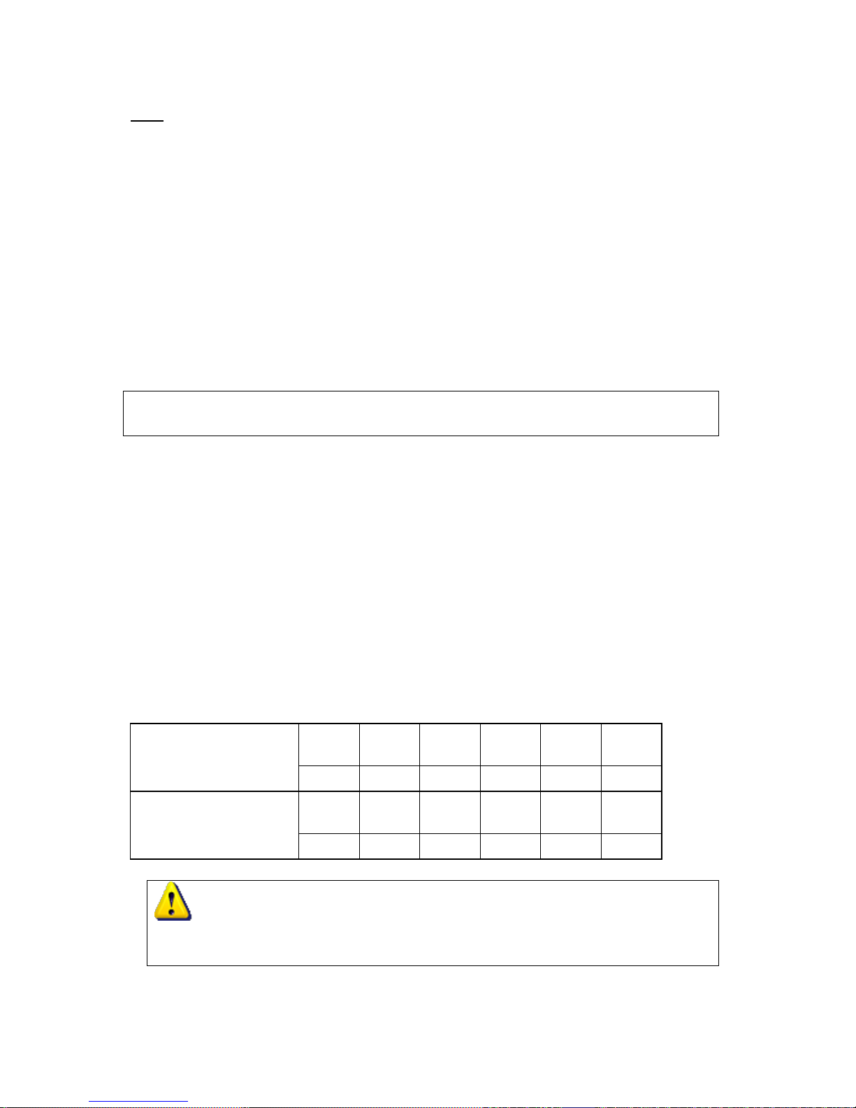
Temp Rise Above
Ground water
30
°F
40
°F
50
°F
60
°F
70
°F
80
°F
Flow Rate(Gal/Min.)
10.6
8.0
6.4
5.3
4.6
4.0
Temp Rise Above
Ground water
90
°F
100
°F
110
°F
120
°F
130
°F
Flow Rate(Gal/Min.)
3.5
3.2
2.9
2.7
2.5
Note: Specifications are subject to change without prior notice. Local and State codes
must be adhered to prior to installation.
Installation Manual and Owner’s Guide WH-321063-NG, WH-321063-LP
ECOHOT TM
4 of 29
INSTALLATION INSTRUCTIONS:
MUST READ PRIOR TO INSTALLATION
Always wear safety glasses and gloves
Must be mounted a min. of 12” above the floor
Finding the Proper Location:
1. Make sure you install your tank-less water heater in an area that exhaust has 4ft or more
from any window or door (check local codes). Exhaust vent must be a min. of 7ft. above
public walk ways or paved drive ways. Minimum 3 feet below eaves or gutters. See Fig 6.
DANGER
Vapors from flammable liquids will explode and catch fire causing death or severe burns.
Do not use or store flammable products such as gasoline, solvents or adhesives near the water heater.
Mounting:
1. Use stud finder or other common method to find wall studs.. It is important to locate the
“flue pipe” between the studs (Use template supplied by ECOHOT). Mount water heater
with a minimum of 2 ½” non-corrosive wood screws. (Note; add a ¼” per ft. (min.) slope to
vent pipe to avoid water damage to the water heater). See Fig 4 &5
2. Use four (4) 1” wood screws for wood siding or molly type screws to mount water heater to
stucco or concrete. (Note: Use corrosion resistant screws).
3. Only use flue pipe supplied by ECOHOT for this unit.
Installation of Gas Line:
1. Ensure that your gas supply is properly sized, check with your local gas company and gas
chart in this manual.
2. Install a gas shut off valve on the gas supply line. (See Fig. 2)
3. Be sure to install a sediment trap and a union connection. (See Fig. 2).
4. Make sure to check the name plate for the correct gas type supply NG or LP.
Installation of Cold Water Supply:
The inlet line, cold water supply is on the right hand side (always use a min. of ¾” copper pipe, or
¾” flex line). Install shut off valve on water supply line. (See Figure 2)
Installation of Hot Water Outlet:
1. The outlet line, hot water supply is on the left hand side (always use a min. of ¾” copper
pipe or ¾” flex line). Install shut off valve on water supply line. (See Figure 2)
2. Your hot water lines should be kept short to save water & energy, thus placement of this
appliance is important to save hot water cost. NOTE: Hot water lines should be insulated.
(Follow local codes).
3. When facing the heater, the hot water outlet is on your left. Keep water inlet and outlet
pipes to no less than 3/4” diameter to allow the full flow capacity.
Remember:

Installation Manual and Owner’s Guide WH-321063-NG, WH-321063-LP
ECOHOT TM
5 of 29
1. Water pressure must be sufficient to activate the heater when drawing hot water from the
top floor.
2. If the hot and cold connections to the heater are reversed, the heater will not function.
3. 3/4’’Copper or brass fittings work best when connected to the connectors. (See Fig. 2)
4. The flexible type connectors (3/4” ID min.) will make installation easier and seals to the
water valve by means of a union connection with a washer type gasket at the joint. No pipe
sealant or Teflon tape is to be used at this joint.
5. Be certain there are no loose particles or dirt in the piping. Blow out or flush the lines
before connecting to the ECOHOTTM. Full port valves should be installed on both the cold
water feed line and the hot water outlet line to facilitate servicing the heater.
6. For installation on a private well system, be sure that the water pressure is set between
30 and 50 PSI. (See Fig. 2)
Installation of Power Supply
The ECOHOTTM water heater requires an electrical power supply from 120 VAC 60HZ circuit
and needs to be properly grounded.
TURNING THE WATER HEATER ON:
1. Open cold water supply valve, open hot water supply valve, and open hot water faucet
outlet to remove any air in the water lines.
2. Turn on gas valve.
3. Plug-in power supply.
4. Press the on/off button on remote to ON then set temperature (ECOHOTTM Recommends
120F/49C or less) and open water outlet in home. If a remote controller is provided,
adjust the temperature below 120F/49C (Default temperature), there is a hot water scald
potential if the remote controller is set too high. Should overheating occur or the gas supply
fail to shut of, turn off the manual gas control valve to the appliance. If water heater does
not get hot close and open outlet again to remove air from gas line, if this does not work
refer to trouble shooting.
TURNING THE WATER HEATER OFF:
1. Shut off hot water faucet.
2. Shut off gas valve.
Please Note:
CSC recommends that installers use large washers with the screws used to hang the heater. (See
Figure3)
Before installing the appliance, be certain you have the correct heater for your type of Gas-Propane
or Natural Gas. Identification labels are found on the shipping box, and on the rating plate, which
is located on the right side panel of the cover.
WARNING: California Proposition 65 lists chemical substances known to the state to cause
Installation Manual and Owner’s Guide WH-321063-NG, WH-321063-LP
ECOHOT TM
6 of 29
cancer, birth defects, death, serious illness or other reproductive harm. This product may contain
such substances, be their origin from fuel combustion (gas, oil) or components of the product itself.
GENERAL RULES TO FOLLOW FOR SAFE OPERATION
1. You should follow these instructions when you install your heater. In the Applianceed states:
The installation must conform with local codes or, in the absence of local codes, the National Fuel
Gas Code ANSI Z223. 1/NFPA54.
In Canada: The installation should conform to CSA B149. Natural Gas and Propane
Installation Code and /or local installation codes.
2. Placement of water heater is important. (Check your local building codes before installation).
If not installed correctly, fatal accidents can occur.
3. The appliance must be electrically grounded in accordance with local codes or, in the absence
of local codes, with the National Electrical Code, ANSI/NFPA 70 and/or the CSA C22.1, Canadian
Electrical Code.
4. The appliance and its individual shutoff valve must be disconnected from the gas supply piping
system during any pressure testing at pressures in excess of 1/2 PSI (3.5Kpa)
5. The appliance must be isolated from the gas supply piping system by closing its individual
manual shut off valve during any pressure testing of the gas supply piping system at test pressures
equal to or less than 1/2 PSI (3.5Kpa).
6. The appliance and its gas connection must be leak tested with soapy water solution before
placing the appliance in operation.
7. Keep water heater area clear and free from combustibles and flammable liquids. Do not locate
the heater over or under any material, which might burn. (See clearances page 19)
8. Should over heating occur or the gas supply fails to shut off, turn off the manual gas control
valve to the appliance.
9. Do not use this appliance if any part has been underwater. Immediately call a qualified service
technician to inspect the appliance and to replace any part of the control system and any gas control,
which has been underwater.
WARNING:
The heater may still operate even when improperly installed. It will, however, be less efficient and
could eventually damage the heater. It could even result in human sickness or death due to carbon
monoxide poisoning. Place your heater as far away from a door or window as possible (4ft. min.).
Anti Freeze Device
This heater is designed for and approved for inside installation.
This water heater has a built in anti freezing device and it has be rated for temperatures down to 5°F
(-15°C) in a wind free environment. Operating this appliance in temperatures lower than 5°F will
void the warranty. If temperatures drop below 5°F it may cause this appliances heat exchange to be
damaged. To avoid freezing, drain water from water heater.
This appliance needs to be plugged in electrical power at all times for anti freezing device to be
operational.
Installation Manual and Owner’s Guide WH-321063-NG, WH-321063-LP
ECOHOT TM
7 of 29
CAUTION: Only the pipes within the water heater are protected by the anti-freeze devices
on the ECOHOTTM. Any hot or cold water pipes located outside of the appliance will not be
protected. Properly protect and insulate these pipes from freezing.
Gas Supply
- It is recommended that the Natural Gas & LP Pipe be standard weight or steel (galvanized or
black) or yellow brass (containing not more than seventy five (75) percent copper). Approved PE
pipe may be used in exterior buried piping systems. All such pipe shall be either new or
previously used for no other purpose than conveying gas; and must be in good condition and free
from internal obstructions. Burred ends shall be reamed to the full bore of the pipe. All fittings used
shall be of malleable iron, yellow brass, or approved plastic fittings. (See gas chart ).
THESE FIGURES ARE FOR ECOHOTTM SUPPLY ONLY; ALL OTHER APPLIANCES IN
THE BUILDING WILL NEED TO BE INCLUDED IN THE PIPE SIZING.
National Fuel Gas Code requires that a sediment trap (drip leg) be installed on gas appliances not so
equipped. The drip leg must be accessible and not subject to freezing conditions. Install in
accordance with the recommendation of the local gas supplier.
WARNING: The heater must be disconnected from the gas supply piping system at test
pressures testing of that system during any pressure testing of that system at test pressure in excess
of 0.5 PSI The water heater must be isolated from the gas supply piping system by closing the
manual shutoff valve during any pressure testing of the gas supply piping system at test pressures
equal to or more than 0.5 PSI.
This water heater includes a pressure regulator and must not be operated at gas supply pressures in
excess of 0.5 PSI. If overpressure has occurred, such as through improper testing of the gas lines or
malfunction of the supply system, the gas valve and regulator must be checked for safe operation.
Make sure that the regulator vent is protected against blockage.
For Natural Gas, the minimum inlet gas pressure is 6 inches W.C.(1.5kPa). For LPG, the minimum
inlet gas pressure is 10 inches W.C.(2.5kPa)
When your connections are made, check for gas leaks at all joints (this includes all existing piping).
Apply soapy water to all gas fittings and gas valve. Soap bubbles are a sign of a leak.
NOTE: No substance other than air, carbon dioxide or nitrogen can be introduced into the gas
piping.
NOTE: If you have a leak, shut off the gas. After verifying the leak, tighten appropriate fittings to
stop leak. Turn the gas on and check again with a soapy solution. Never test for gas leaks using a
match or flame.

Installation Manual and Owner’s Guide WH-321063-NG, WH-321063-LP
ECOHOT TM
8 of 29
Gas Piping, Connections and Gas Regulator
Before connecting the gas supply, check the rating plate on the right side of the right front cover to
be sure that the heater is rated for the same gas to which it will be connected.
In the Applianceed States: The installation must conform with local codes or, in the absence of local
codes, the National Fuel Gas Code ANSIZ223.1/NFPA54.
In Canada: The installation should confirm with CGAB149 INSTALLATION CODES and/or local
installation codes.
Gas Line Sizing:
The gas supply piping should be sized according to the Applicable Plumbing Code for a maximum
draw of 218,000 BTU. First determine the effective length of the gas supply line by measuring the
actual length of piping, and then adding 5 ft. for every elbow or “T” to the actual length. Use the
charts below to determine the pipe diameter necessary to accommodate the BTU demand of the
appliance. If there is more gas drawing appliances on the line, size according to the maximum
amount of BTU demand.
Maximum Liquified Petroleum(Undiluted) delivery Capacity in Thousand of Btuh(0.5” WC
Pressure Drop)
Pipe
Size
Length in Feet
10’
20’
30’
40’
50’
60’
70’
80’
90’
100’
125’
150’
200’
½”
275
189
152
129
114
103
96
89
83
78
69
63
55
¾”
576
693
315
267
237
217
196
185
173
162
146
132
112
1”
1107
732
590
504
448
409
378
346
322
307
275
252
213
1 ¼”
1220
1149
1121
1103
913
834
771
724
677
630
567
511
440
1 ½”
1330
1229
1185
1155
1141
1127
1118
1108
1102
976
866
787
675
2”
1622
1433
1346
1299
1264
1239
1220
1204
1192
1811
1606
1496
1260
**For reference only. Please consult gas pipe manufacture for actual capacities.
The formula for figuring the cubic feet per hour required is:
Gas Input of Water Heater(BTU/HR)
CFH = ------------------------------------------------- Heating Value of Gas(BTU/Cubic FT)
Maximum Liquified Petroleum(Undiluted) delivery Capacity in Thousand of Btuh(0.5” WC
Pressure Drop)
Pipe
Size
Length in Feet
10’
20’
30’
40’
50’
60’
70’
80’
90’
100’
125’
150’
200’
½”
275
189
152
129
114
103
96
89
83
78
69
63
55
¾”
576
693
315
267
237
217
196
185
173
162
146
132
112
1”
1107
732
590
504
448
409
378
346
322
307
275
252
213
1 ¼”
1220
1149
1121
1103
913
834
771
724
677
630
567
511
440
1 ½”
1330
1229
1185
1155
1141
1127
1118
1108
1102
976
866
787
675
2”
1622
1433
1346
1299
1264
1239
1220
1204
1192
1811
1606
1496
1260
**For reference only. Please consult gas pipe manufacture for actual capacities.
This chart is only for Black Iron piping and is only for ECOHOT Water Heater at high fire
condition.
High Altitude Operation
For high altitude installations in Canada above 2,000 Ft to 4,500 Ft, this water heater's Gas Supply
needs to be derated 5% for Inside Models and 10% for Outside Models (See owner's manual for
instructions on de-rating)
Installation Manual and Owner’s Guide WH-321063-NG, WH-321063-LP
ECOHOT TM
9 of 29
For high altitude installations in US above 7,500 Ft, contact Greenworks Unlimited for instructions.
Do not alter the orifice jets or gas supply pressure.
This Water Heater is not approved above 9,000 ft (2,743m).
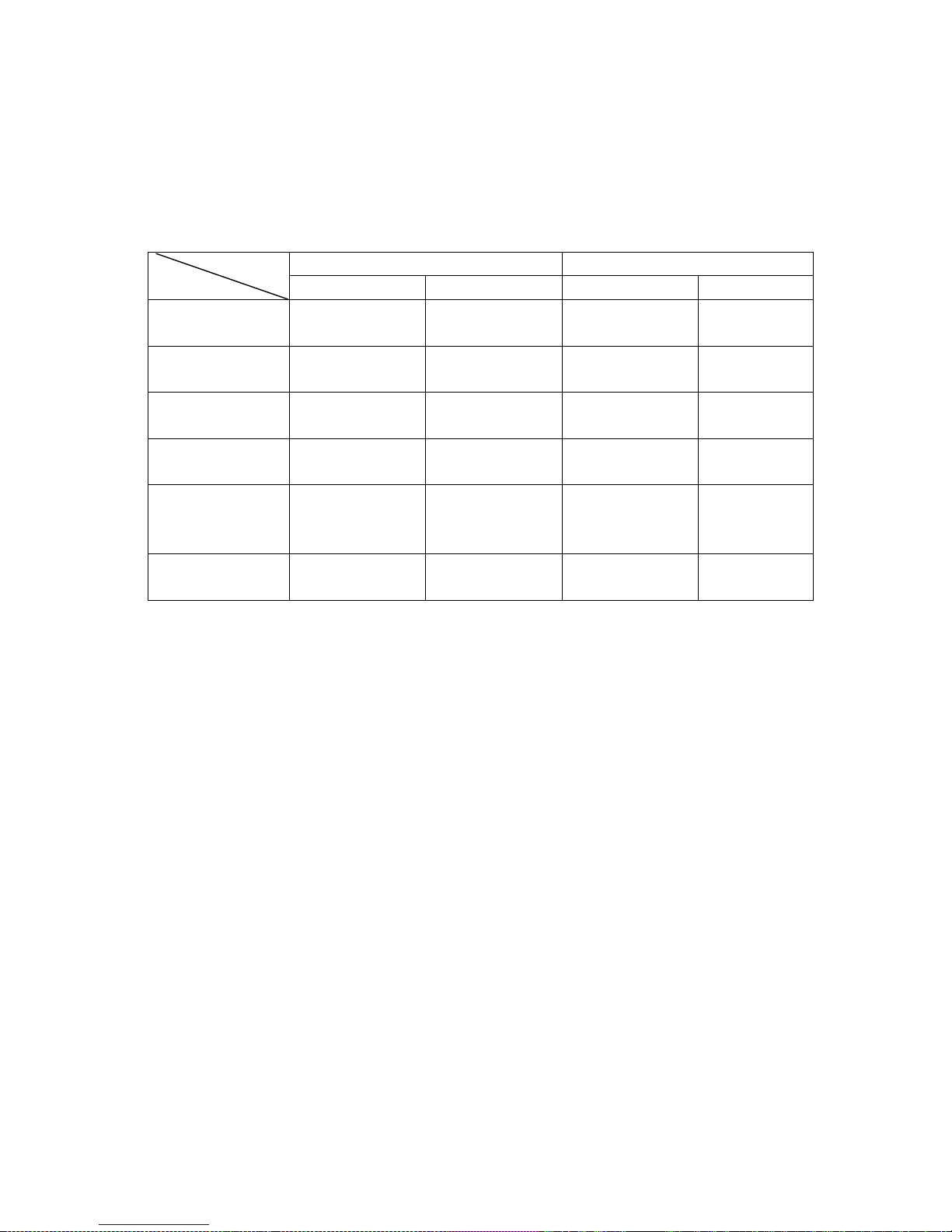
De-rating Manifold Pressure
De-rating Manifold Pressure Table
WH-201061, WHO-201059
WH-321063, WHO-321064
LPG
NG
LPG
NG
Normal Max.
Manifold Pressure
7.0 inches W.C.
(1750±30)Pa
3.1 inches W.C.
(780±30)Pa
8.0 inches W.C.
(2000±30)Pa
4.4 inches W.C.
(1100±30)Pa
Normal Min.
Manifold Pressure
1.4 inches W.C.
(350±20)Pa
0.6 inches W.C.
(150±20)Pa
1.4 inches W.C.
(350±20)Pa
0.6 inches W.C.
(150±20)Pa
De-rating 5% Max.
Manifold Pressure*
6.3 inches W.C.
(1580±30)Pa
2.8 inches W.C.
(705±30)Pa
7.2 inches W.C.
(1800±30)Pa
4.0 inches W.C.
(990±30)Pa
De-rating 5% Min.
Manifold Pressure*
1.3 inches W.C.
(315±20)Pa
0.5 inches W.C.
(135±20)Pa
1.3 inches W.C.
(315±20)Pa
0.5 inches W.C.
(135±20)Pa
De-rating 10%
Max.
Manifold Pressure*
5.7 inches W.C.
(1420±30)Pa
2.5 inches W.C.
(635±30)Pa
6.6 inches W.C.
(1650±30)Pa
3.6 inches W.C.
(895±30)Pa
De-rating 10% Min.
Manifold Pressure*
1.1 inches W.C.
(285±20)Pa
0.5 inches W.C.
(125±20)Pa
1.1 inches W.C.
(285±20)Pa
0.5 inches W.C.
(125±20)Pa
(1 inch water column equals 249.089 Pascals (at 4 degree Celsius), 1 Pa=0.004015 in.W.C.)
*: For High Altitude installation in Canada between 2,000 Ft and 4,500 Ft , Indoor Model de-rating
5% and outdoor model de-rating 10%,
**: Natural Gas Pressure Inlet: Max. 10.5” WC(2.6kPa), Min. 6” WC(1.5kPa).
***: LP Gas Pressure Inlet: Max. 14” WC(3.5kPa). Min. 10” WC(2.5kPa).
1. Connecting manometer
◆ Shut off gas.
◆ Remove front cover and locate Manifold Pressure measuring point, see Fig:Test Point
below “T”.
 Loading...