

Greenworks 24052 User Manual
15A YARD CHIPPER
24052
Owner’s Manual
(888.909.6757)
TOLL-FREE HELPLINE: 1-888-90WORKS
Read all safety rules and instructions carefully before operating this tool.

CONTENTS
Contents .............................................................................................................................. 2
.......................................................................................................... 2
Safety information ............................................................................................................. 3 -4
Symbols ............................................................................................................................5-6
Electrical ........................................................................................................................... 7- 8
Know your yard chipper ....................................................................................................... 9
Assembly instructions ................................................................................................... 10-13
Operation ...................................................................................................................... 14 -17
Maintenance ................................................................................................................. 18 -19
Warrant y ............................................................................................................................ 20
Exploded view ............................................................................................................... 21-22
Parts list ........................................................................................................................ 23-25
Notes ............................................................................................................................ 26-27
PRODUCT SPECIFICATIONS
15A YARD CHIPPER
Motor .............................................................................................. 120V AC, 60 Hz, 15A
No-load speed ............................................................................................... 4,00 0 RPM
Maximum cutting diameter .......................................................................1-3/8" (35 mm)
Height ................................................................................................... 37-1/2" (950 mm)
Weight .................................................................................................... 30.8 lbs. (14 kg)
2

SAFETY INFORMATION
IMPORTANT SAFETY INSTRUCTIONS
I M P O R T A N T
READ AND UNDERSTAND ALL INSTRUCTIONS. Failure to follow all instructions listed below
may result in electric shock, re, and/or serious personal injury.
W A R N I N G
TO AVOID MISTAKES THAT COULD CAUSE SERIOUS INJURY, DO NOT PLUG IN THE
CHIPPER UNTIL THE FOLLOWING STEPS HAVE BEEN READ THOROUGHLY.
• READ and become familiar with this entire instruction manual. LEARN the tool’s applications,
limitations, and possible hazards.
• AVOID DANGEROUS CONDITIONS. DO NOT use power tools in wet or damp areas or
expose them to rain.
• DO NOT use power tools in the presence of ammable liquids or gases.
• KEEP BYSTANDERS AT A SAFE DISTANCE FROM the work area when the tool is operating.
NEVER allow children near the tool.
• DO NOT FORCE THE TOOL to do a job for which it was not designed.
• DRESS FOR SAFE TY. DO NOT wear loose clothing, gloves, neckties, or jewelr y (rings,
watches, etc.) when operating tool. Loose clothing can get caught and pull you into moving
parts.
• ALWAYS WEAR EYE PROTECTION.
• ALWAYS remove the power cord plug from the electric outlet when making adjustments,
changing parts, cleaning or working on the tool.
• AVOID ACCIDENTAL START-UPS. Make sure the power switch is in the OFF position before
plugging in the power cord.
• DO NOT abuse the power cord. Do not use it to carry the tool. Keep cord away from heat, oil,
sharp edges, or moving parts. Replace damaged cords immediately; they may create a shock
or re hazard.
• NEVER LEAVE A RUNNING TOOL UNATTENDED. Turn the power switch to OFF. Do not
leave the tool until it has come to a complete stop.
• Keep proper footing and balance at all times. Wear oil-resistant, rubber-soled footwear.
• ALWAYS keep tool clean and in good working order.
• Check for proper alignment of moving parts, binding, breakage, or any other conditions that
may affect the tool’s operation. Any part that is damaged
• DO NOT operate tool if you are under the inuence of any drugs, alcohol or medication that
could affect your ability to use the tool properly.
• Do not use solvents, brake uids, gasoline, or other petroleum products to clean the tool; they
may damage plastic parts.
3

SAFETY INFORMATION
ALWAYS WEAR EYE PROTECTION.
A yard chipper can throw foreign objects into your eyes which could cause
permanent eye damage.
ALWAYS wear safety goggles (not glasses). Ordinary eyeglasses have only
impact-resistant lenses—they are NOT safety goggles.
SPECIFIC SAFETY RULES FOR YARD CHIPPERS
• Be thoroughly familiar with the operation of the chipper before initial use.
• NEVER put your hands into the hopper. Always use the push stick supplied with your chipper
to push items into the hopper.
• DO NOT try to force objects that exceed the recommended diameter and capacity of the
chipper: 1-3/8" (35 mm).
• AVOID ACCIDENTAL START-UPS. Be sure switch is OFF when plugging in.
• DO NOT FORCE THE CH
the rate for which it was designed.
• Before put ting obje cts into the hopper, remove any stones, debris, or objects that could
damage the blades.
• During operation, ensure that there are no other persons or animals within a radius of 10 feet.
Stop using the machine while people, especially children, or pets, are nearby.
• NEVER reach under the chipper until it has
rotate for a time after being switched OFF.
• MAK E all adjustments with the power OFF and the chipper disconnected from the power
source.
• ALWAYS use acce ss or ies provide d or re comm en ded by t he manu facturer. Do not use
substitutes.
• KEEP guards in place and in working order. Keep blades sharp. Keep hands and feet away
from cutting areas.
IPPER. It will do the job better and with less likelihood of injur y at
completely stopped. The blade may continue to
W A R N I N G
NEVER PLACE HANDS NEAR DISCHARGE CHUTE. FAILURE COULD RESULT IN SERIOUS
INJURY.
W A R N I N G
NEVER REACH INTO THE HOPPER UNTIL THE CHIPPER HAS COME TO A COMPLETE
STOP AND IS UNPLUGGED. THE CHIPPER WILL CONTINUE TO ROTATE FOR A FEW
SECONDS AFTER IT IS SWITCHED OFF.
SAVE THESE INSTRUCTIONS
4
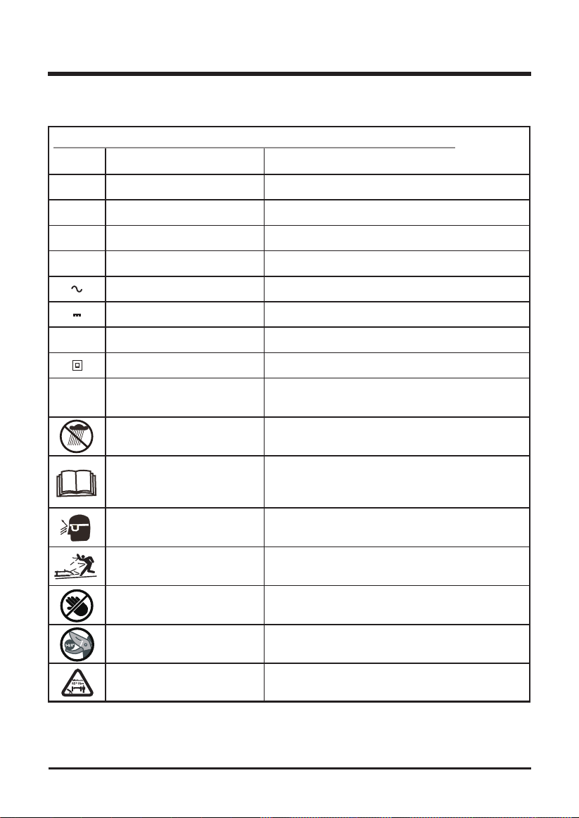
SYMBOLS
Some of the following symbols may be used on this product. Please study them and learn their
meaning. Proper interpretation of these symbols will allow you to operate the product better and safer.
SYMBOL NAME DESIGNATION/EXPLANATION
V Volts Voltage
A Amperes Current
Hz Hertz Frequency (cycles per second)
W Watts Power
min Minutes Time
Alternating Current Type of current
Direct Current Type or a characteristic of current
n
o
No Load Speed Rational speed, at no load
Class II Construction Double-insulated construction
/min Per Minute Revolutions, strokes, surface speed, orbits etc.,
per minute
Wet Conditions Alert Do not expose to rain or use in damp locations
Read The Operator’s Manual To reduce the risk of injury user must read and
understand operator’s manual before using this
product.
Eye Protection Wear eye protection when operating this equipment.
Ricochet Thrown objects can ricochet and result in personal
injury or property damage.
Sharp Blade Danger – Keep hands and feet away from blade.
Cutting Capacity Cutting capacity: 1-3/8” (3.5 cm)
Keep Bystanders Away Keep all bystanders at least 50 ft. away.
5
SYMBOLS
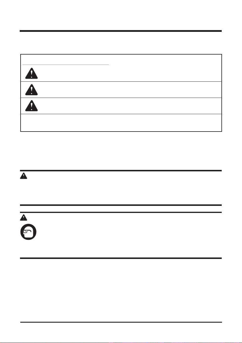
The following signal words and meanings are intended to explain the levels of risk associated
with this product.
SYMBOL SIGNAL MEANING
DANGER Indicates an imminently hazardous situation, which, if not
avoided, will result in death or serious injury.
WARNING Indicates a potentially hazardous situation, which, if not avoided,
could result in death or serious injury.
CAUTION Indicates a potentially hazardous situation, which, if not avoided,
may result in minor or moderate injury.
CAUTION (Without Safety Alert Symbol) Indicates a situation that may
result in property damage.
SERVICE
Servicing requires extreme care and knowledge and should be performed only by a qualified
service technician. For service we suggest you return the product to your nearest AUTHORIZED
SERVICE CENTER for repair. When servicing, use only identical replacement parts.
W A R N I N G
To avoid serious personal injury, do not attempt to use this product until you have read this
Owner's Manual thoroughly and understand it completely. If you do not understand the warnings
and instructions in this Owner's Manual, do not use this product. Call the Toll-free Helpline (1888-909-6757) for assistance.
W A R N I N G
The operation of any power tool can result in foreign objects being thrown into your
eyes, which can result in severe eye damage. Before beginning power tool operation,
always wear safety goggles or safety glasses with side shields and, when needed, a
full face shield. We recommend Wide Vision Safety Mask for use over eyeglasses or
standard safety glasses with side shields. Always use eye protection which is marked
to comply with ANSI Z87.1.
SAVE THESE INSTRUCTIONS
6
ELECTRICAL
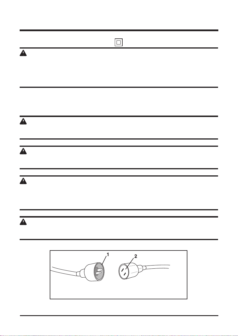
DOUBLE INSULATED (See Figure 1)
W A R N I N G
TO AVOID ELECTRIC SHOCK HAZARDS, FIRE HAZARDS, OR DAMAGE TO THE TOOL, USE
PROPER CIRCUIT PROTECTION. YOUR CHIPPER IS WIRED AT THE FACTORY FOR 12O-V
OPERATION. CONNECT TO 120-V, 15-Amp CIRCUIT AND USE A 15-Amp CIRCUIT BREAKER.
TO AVOID SHOCK OR FIRE WHEN THE POWER CORD IS WORN, CUT, OR DAMAGED IN
ANYWAY, REPLACE IT IMMEDIATELY.
This yard chipper has a plug that looks like the one shown in Fig. 1. The yard chipper is double
insulated to provide a dual thickness of insulation between you and the tool’s electrical system.
All exposed metal parts are insulated.
W A R N I N G
TO AVOID INJURY, WHEN SERVICING THE CHIPPER USE ONLY IDENTICAL REPLACEMENT
PARTS.
W A R N I N G
DOUBLE INSULATION DOES NOT TAKE THE PLACE OF NORMAL SAFETY PRECAUTION
WHEN OPERATING THIS TOOL.
W A R N I N G
TO AVOID ELECTRIC SHOCK:
1. Use only identical replacement parts when serving a tool with double insulation. Servicing should
be performed by a qualied technician.
2. Do not use in wet or damp or expose to rain.
C A U T I O N
IN ALL CASES, MAKE CERTAIN THE RECEPTACLE IN QUESTION IS PROPERLY GROUNDED.
IF YOU ARE NOT SURE, HAVE A CERTIFIED ELECTRICIAN CHECK THE RECEPTACLE.
1) 2-prong plug
2) Properly grounded extension cord
Fig. 1
7

ELECTRICAL
W A R N I N G
THIS LAWN TOOL IS FOR OUTDOOR USE ONLY. DO NOT EXPOSE TO RAIN OR USE IN
DAMP LOCATIONS.
GUIDELINES FOR USING EXTENSION CORDS
Make sure your extension cord is in good condition. When using an extension cord, be sure to
use one of heavy enough gauge to carry the current your product will draw. An undersized cord
will cause a drop in line voltage resulting in loss of power and overheating. The table below
shows the correct size to be used according to cord length and nameplate ampere rating. If in
doubt, use the next heavier gauge. The smaller the gauge number, the heavier the cord.
MINIMUM GAUGE FOR EXTENSION CORDS (AWG)
(WHEN USING 120 V ONLY)
Amp Rating Total Length of Cord in Feet (meters)
More Than Not More Than 25' (7.6 m) 50' (15 m) 100' (30.4 m) 150' (45.7 m)
0 6 18 16 16 14
6 10 18 16 14 12
10 12 16 16 14 12
12 16 14 12 Not Recommended
Be sure your extension cord is properly wired and in good condition. Always replace a damaged
extension cord or have it repaired by a qualified person before using it. Keep your extension
cords away from sharp objects, excessive heat and damp or wet areas.
Use a separate electrical circuit for your tools. This circuit must not be less than 12-gauge cord
and should be protected with a 15-amp time delayed fuse. Before connecting the motor to the
power line, make sure the switch is in the OFF position and the electric current is rated the same
as the current stamped on the motor nameplate. Running at a lower voltage will damage the
motor.
W A R N I N G
THIS TOOL MUST BE GROUNDED WHILE IN USE TO PROTECT THE OPERATOR FROM
ELECTRICAL SHOCK.
SAVE THESE INSTRUCTIONS
8
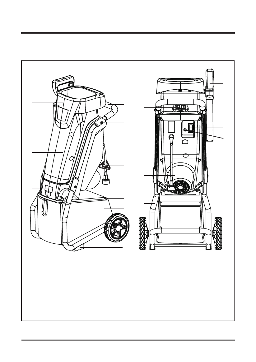
KNOW YOUR YARD CHIPPER
Read this operator's manual and safety rules before operating your yard chipper. Compare the
illustration in Figure 2 to your yard chipper in order to familiarize yourself with the location of
various controls and adjustments. Save this manual for future reference.
12
1
3
7
1. Hopper
2. Handle
3. Housing
4. Motor Housing
5. Release Knob
6. Power Switch
7. Discharge Chute
2
5
14
15
4
10
8
11
13
8. Stand with Wheels
9. Circuit Breaker
10. Bracket
11. Collection bag
12. Push Paddle
13. Rubber Foot
14. Push Bar
15. Cord Lock
6
9
NOTE: Remove label from push paddle prior to use.
9
Fig. 2
 Loading...