

Greenwood Unity CV100 Installation Instructions Manual

Unity CV100
Constant Volume Single Point Extract Fan
INSTALLATION INSTRUCTIONS
For further information contact the Greenwood Customer Services Department
Greenwood Air Management Ltd
Greenwood House, Brookside Avenue, Rustington, West Sussex BN16 3LF
Tel: 01903 771021 Fax: 01903 782398
Email: info@greenwood.co
.uk www
.greenwood.co.uk
EC Declaration of Conformity
We Declare that Type CV100
Fan conforms to 89/336/EEC
73/23/EEC
This Greenwood product CV100 is guaranteed for a period of 2 years from the date of purchase of the Product against fault in manufacture. In case of such fault in manufacture
apparent during the Guarantee Period, Greenwood may, at its absolute discretion, repair the product, replace the product free of charge or refund the cost of the product AS LONG AS
AND ONL
Y IF
:
1. The Product is returned to Greenwood within the Guarantee Period with evidence of purchase date:
2. The Product has not been misused or handled carelessly or used on an inappropriate voltage supply;
3. Repairs have not been attempted other than by Greenwood's service staff or authorised dealers; and
4. In Greenwood's sole discretion, the Product is found to be faulty. If it were not found to be faulty, the Product would be available for collection from the relevant
Greenwoods premises within one calendar month and if it was not collected, it would be subsequently delivered by Greenwood and a delivery charge will be made.
(the guarantee)
This guarantee does not confer any rights other than those expressly set out above and does not cover any claims for consequential
loss, damage or any costs incurred in the replacement of the faulty P
roduct. This Guarantee is offered as an extra benefit and
does not affect your statutory right as a consumer.
The Guarantee Period
4
READ ALL INSTRUCTIONS
BEFORE COMMENCING
INSTALLATIONS
• Obser
ve appropriate safety precautions if
working on steps or ladders. Wear eye
protection when breaking out wall or window
materials etc.
• The fans should not be sited where it would
be subject to a direct source of heat in
excess of 40ºC.
• When installing wall mounted fans, ensure
that there are no buried cables or pipes in
the way. It is recommended that this fan is
mounted 1.8m above floor level.
• A clearance of 75mm to be allowed on at
least one side of the fan for the removal of
the internal grille.
WARNING:
Always isolate fan from mains supply
before cleaning.
Do not use solvents to clean this fan.
•
Loosen the two retaining screws under
grille (Do not remove screws), then
pull bottom of grille while lifting.
• The fan may now be cleaned using a
brush, cotton bud or damp cloth.
DO NOT IMMERSE IN WATER.
•
Keep points 1 (sensor) and 2
(impeller) clean for best performance.
• After cleaning replace Internal Grille .
To Clean or Service Fan
05.10.753 GW64100140G Issue 1 October 2006
WARNING:
Isolate electricity supply
before removing or
replacing jumper switch.
•
Remove jumper switch if
10 L/S constant airflow rate
is required.
• Replace jumper switch if
5 L/S constant airflow rate
is required.*
* Factory set at 5 L/S.
Constant Airflow Settings
Greenwoods Unity CV100 is a continuously
running extract fan, designed to offer a
simplistic approach to the Building
Regulations and an energy efficient domestic
ventilation solution. The design concept
revolves around 'one product', which has been
designed to be flexible in application and to
meet the performance requirements of all wet
rooms within a dwelling (to be configured
during installation). Offering varying
installations including through wall, ceiling
and inline options, the Unity fan is also silent
in operation and is supplied with an
aesthetically styled internal grille.
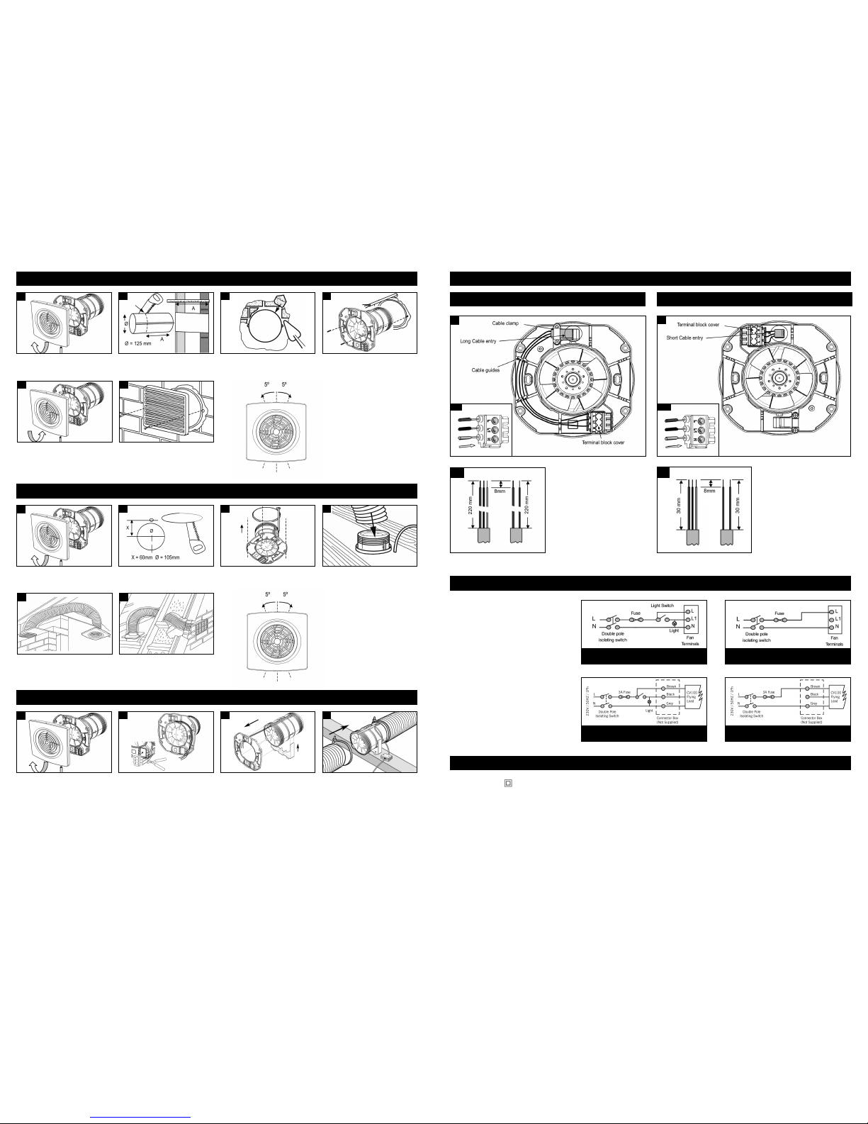
1
2
3
6
4
5
Wall Mounting (Using ED wall duct and EG external grille)
2 3
L
oosen the two retaining screws under grille
(Do not remove screws), then pull bottom of
g
rille while lifting.
C
ut the duct to width of the plasterboard
or tiled wall with slight fall to exterior.
(
Make provisions for cable).
F
ill in any gaps with mortar or foam and
make good internal and external walls.
M
ake sure that ducting remains circular
and screw holes are horizontal.
U
sing No 8 screws, secure fan body to
ducting. The electrical cable passes through
a
s appropriate. Wire fan (See wiring details).
Replace internal grille by hooking the top of
grille onto main body then push bottom of grille
h
ome. Gently tighten retaining screws at bottom
of grille, ensuring no wires are trapped.
Screw the protective wall grille over the
external duct opening.
F
ine Adjustments
I
f after installation the fan is not
level, the front grille can be
t
urned upto 5º clockwise or 5º
a
nti-clockwise to correct this.
1
2
3
6
4
5
Ceiling Mounting
Loosen the two retaining screws under grille
(Do not remove screws), then pull bottom of
grille while lifting.
Cut an opening through the ceiling for the
fan and electrical cable.
Secure to ceiling using suitable fixing method
then W
ire fan (See wiring details).
Place flexible ducting over the spigot of the
fan
. Fit ducting to spigot using ties. R
eplace
front grille.
Diagram depicting typical installation ducted
through roof soffit.
Diagram depicting typical installation ducted
through roof to external wall.
1
2
3
4
In Line Mounting
Loosen the two retaining screws under grille
(Do not remove screws), then pull bottom of
grille while lifting. Discard the grille.
Carefully cut the wiring from the connector
block on the backplate.
Unclip the backplate from the fan body.
Secure the fan body to a suitable roof beam or
similar using the mounting foot supplied. The
electrical cable can then be wired using a
suitable shrouded connector block as
appropriate. Wire fan (See wiring diagrams).
P
rovide appropriate mechanically protected
sleeve to flying lead, to comply with current
IEE wiring regulations.
Place flexible ducting over the spigot of both
ends of the fan body. Fit ducting to spigot
using ties. 100mm ducting and grilles are
recommended for in line mounting.
• S
trip cable to correct lengths as shown
in diagram 1.b.
• Insert cable through cable entry point,
then clamp cable using the cable clamp.
• U
se the cable guides to retain the cable
wires, then push the wires into the
terminal block until cable comes to a
d
ead stop. (Diagram 1.a)
• Peel open the terminal cover,
so that
t
erminal screws are visible, then tighten
s
crews and replace terminal cover
,
making sure that cover is fully replaced.
• S
trip cable to correct lengths as shown
in diagram 2.b.
• Break open cable entry point then insert
cable.
• P
ush the wires into the terminal block
u
ntil cable comes to a dead stop.
(Diagram 2.a)
• P
eel open the terminal cover, so that
terminal screws are visible, then tighten
screws and replace terminal cover,
m
aking sure that cover is fully replaced.
The electrical connections must be carried out by a
qualified electrician in accordance with IEE or local
regulations.
WARNING:
Isolate electricity supply before starting work.
• The fans are double insulated and do not require an
earth connection.
• The fans must be connected to a double pole isolating
switch having contact separation of at least 3 mm.
• When supplied from a 5 amp lighting circuit no local
fuse is required.
1
2
1.b
2.b
1
.a
2.a
Wiring Details
Installation Method 1
Installation Method 2
Wiring Diagrams
Fan Specifications
220/240V/ 50Hz / 1Ph IP24
5.5 Watts max.
5, 10 & 15 L/S airflow performance
With Boost Without Boost
In Line Mounting With Boost In Line Mounting Without Boost
230V / 50Hz / 1Ph
230V / 50Hz / 1Ph
Cable Sizes:
Fixed flat wiring 2 core 1mm
2
3 core 1/1.5mm
2
F
ine Adjustments
If af
ter installation the fan is not
level, the front grille can be
turned upto 5º clockwise or 5º
anti-clockwise to correct this.
 Loading...