

Greenwood Fusion HRV2HT Installation Instructions Manual
Fusion
HRV2HT
Mechanical Ventilation with Heat Recovery
Installation Instructions
Commissioning Data:
To be completed by the Commissioning Engineer.
Refer to User/Homeowner Guide also supplied.
Page | 2
Contents
1. General Description /
Physical Specification
Page 2
2.
Installation Instructions
Page 3
General Preparation
Page 3
Positioning
Page 3
Mounting
Page 6
Condensate Drain
Page 9
Ducting Guidelines
Page 9
Electrical
Page 10
Wiring Diagrams
Page 11
Connecting to the BMS
Page 12
On Site Commissioning
Page 14
3.
Guarantee
Page 23
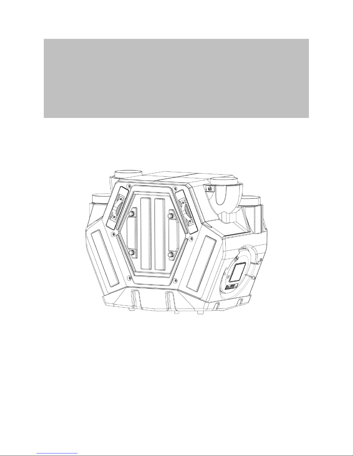
1.0 General Description / Physical Specification
1.1
1.1.1
1.1.2
1.1.3
1.1.4
1.1.5
1.1.6
1.1.7
1.1.8
Overview
The HRV2HT is a ventilation system designed to provide improved indoor air quality in dwellings. As a whole
house system, the unit continuously extracts air from the non-habitable rooms and supplies fresh, filtered air
to habitable rooms. Heat that is recovered from the air drawn from the bathrooms and kitchen is passed
through a heat exchanger and the heat that is recovered is transferred, to temper the supply air in habitable
rooms to provide a comfortable indoor environment.
A boost speed facility is provided to increase the ventilation rate, e.g. when cooking or showering, providing
a comfortable indoor environment. A wireless boost switch (not supplied) such as GRF1 or GRF2 can be
used to provide this operation. Alternatively a GS2 Switch Live boost switch can be used to provide this
operation (See Section 2.6 Electrical).
This product features on SAP Appendix Q as a high efficiency version and part of the process requires the
Installation Checklist for MVHR products to be completed and submitted to building control, available at
www.sap-appendixq.org.uk, along with all other relevant paperwork.
Record sheets for commissioning information are provided, please refer to section 6 of the User/Homeowner
Guide also supplied with HRV2HT.
Ancillary Items Required
125mm Ducting (rectangular ducting can be used, where appropriate)
GRF1 Digital radio frequency device for commissioning and switching between trickle, medium and
boost
GRF2 Radio frequency switch providing switching between trickle, medium and boost (option)
GS2 Hardwired switch providing switching between trickle and boost (option)
Packaging Includes –
1 x HRV2HT Unit
1 x Wall Fixing Bracket
1 x Installation Instructions
1 x User/Homeowner Guide
The appliance is not intended for use by young children or infirm persons unless they have been adequately
supervised by a responsible person to ensure that they can use the appliance safely. Young children should
be supervised to ensure that they do not play with the appliance.
Siting Notes: Where an open-flued oil or gas-fuelled appliance is installed in the kitchen, extract ventilation
can cause the spillage of flue gases. Care must be taken to ensure ventilation is reduced appropriately, as
set out in the Building Regulations. Kitchens with solid-fuel appliances should not have extract fans fitted.
Page | 3
1.2
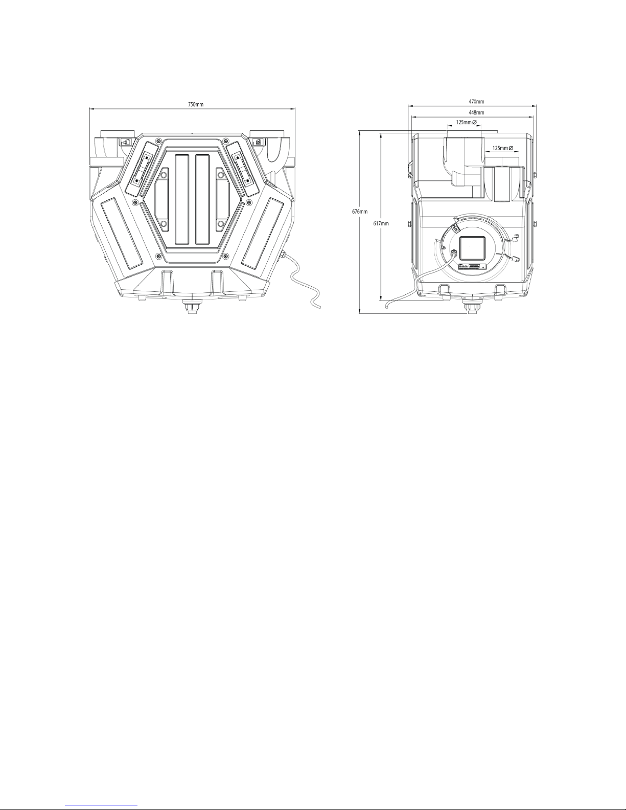
Physical Specification
Front View Side View
2.0 Installation Instructions
2.1
2.1.1
2.1.2
2.1.3
2.1.4
2.1.5
2.2
2.2.1
2.2.2
2.2.3
2.2.4
General Preparation
The HRV2HT unit is supplied with 4 x 125mmØ spigots.
125mm ducting with connectors can be used (see ancillary section page 2) to provide performance levels
required for compliance with Building Regulations.
Installation of the HRV2HT should be in accordance with the current editions of Building Regulations and
BS7671: IEE Wiring Regulations.
The design, material specification and installation must only be carried out by ‘competent persons’. Electrical
installation must be carried out by a qualified Electrician.
IMPORTANT NOTE Gases from fuel-burning equipment must not be drawn into any living areas. If any
room, where air is extracted, contains a fuel burning appliance such as a central heating boiler, then either of
the following should be undertaken:
– The flue must be of the room sealed or balanced flue type or;
– Allowance must be made for an adequate supply of air into the room.
Positioning
The unit must be installed vertically and wall mounted to enable effective condensate drainage in either a
service cupboard or secured to a vertical structure in the loft space. Duct spigots must be upright at top of
unit.
It is not advisable to install the unit directly above a bedroom or living room ceiling, or in an area that is part
of a living area or bedroom.
Consideration must be given to allow for adequate access for servicing, maintenance and any fault
diagnostics (See Figure 9 on Page 7).
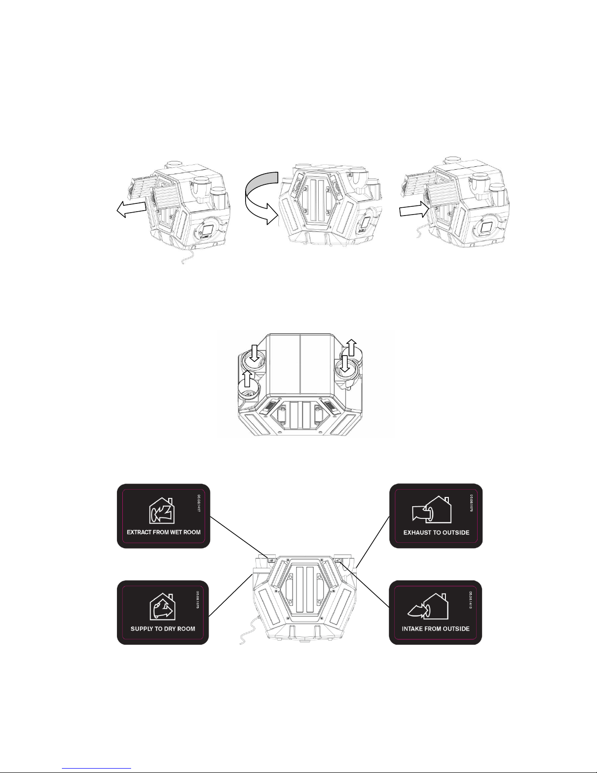
The unit can be configured for right and left hand installation (See Figures 1 to 3 overleaf).
Page | 4
2.2.5
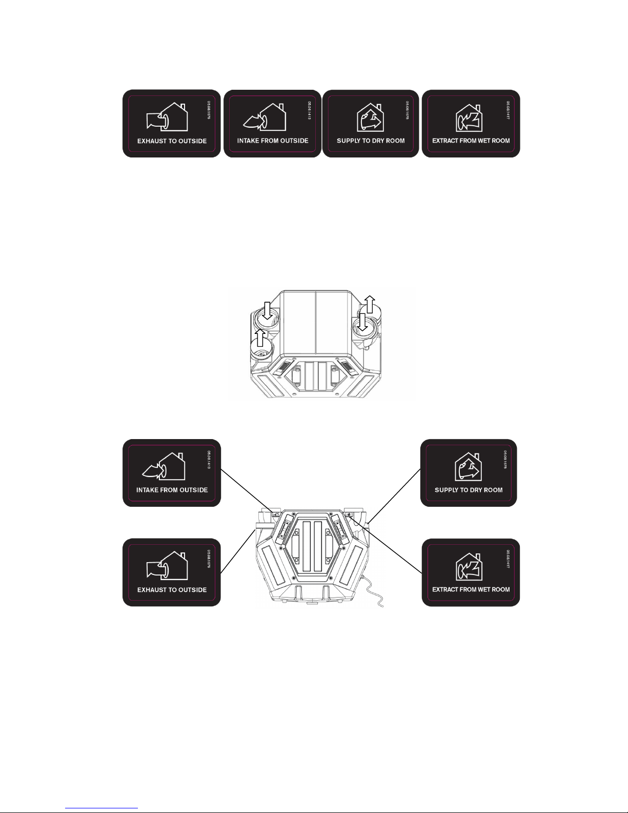
Configuration Symbols
Exhaust Air Intake Air Supply Air Extract Air
Exhaust Air
Intake Air
Supply Air
Extract Air
– Port to exhaust stale air to outside
– Port to intake fresh air from outside
– Port to supply fresh air to dry rooms
– Port to extract stale air from kitchen and wet rooms
Right Hand Configuration (factory setting) (See Figure 1)
Top View
Front View
Supply Air
Extract
Intake
Exhaust
Figure 1
2.2.6
Page | 5
2.2.7
Left Hand Configuration
The handing of the unit can be changed by following the 3 steps as shown below (See Figure 2), and does
not require any internal changes.
1) Remove both filters from the unit.
2) Rotate unit through 180 degrees.
3) Reinsert both filters into the unit.
Step 1 Step 2 Step 3
The unit is now in left hand configuration mode with altered duct connections (See Figure 3).
Top View
Front View
Intake
Exhaust
Supply Air
Extract
Figure 3
180○
Figure 2
Page | 6
2.3
2.3.1
2.3.2
2.3.3
2.3.4
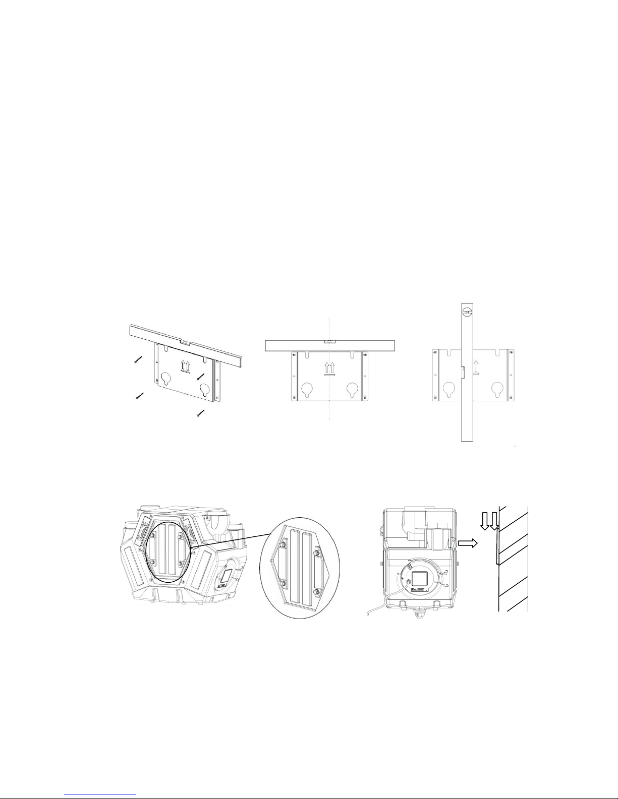
Mounting (Vertical Installation Only)
The HRV2HT unit is supplied with one wall fixing bracket. The bracket has six fixing points available; four of
these are slotted, and located in each corner. Minimum acceptable number of fixing points for mounting is
four. Screws and fixings not supplied.
Proceed to align the wall bracket taking into account the available wall space to mount the unit, ensuring that
the wall can support 20kg.
Use a spirit level to assist mounting and levelling the bracket (See Figures 4 & 5). Use ‘V’ slots located top
and bottom of bracket to mark a vertical pencil line (See Figure 6), and securely fix bracket to wall using
suitable fixings. Total product weight when running 20kg.
The HRV2HT unit fixes to the bracket by aligning the four mounting studs on the rear panel (See Figure 7),
with the large holes and slots on the fixing bracket (See Figure 4 or 5). You can also use the pencil line
drawn earlier as a guide (See Figure 6), using the V cut out on the front of the product to align. Once the
mounting studs are located correctly, slide the product downwards so that it is securely mounted to the wall
(See Figure 8).
Note;
There should be no movement once correctly located and the filters should be accessible from the
front of the unit.
2
1
Figure 4
Figure 5
Figure 7
Figure 8
Figure 6
Page | 7
2.3.5
2.3.6
2.3.7
Access for Maintenance
Figure 9
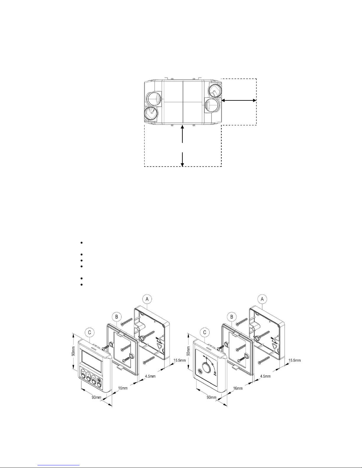
Controller Mounting
The GRF1 and GRF2 controllers can be mounted to the wall, however only the GRF1 controller can be
mounted to the HRV2HT unit. The controller is supplied with one back box, one fixing plate and one screw
and raw plug set.
Wall Mounting (See Figure 10)
Using the four countersunk screws and four raw plugs supplied, mount the back box (A) to a flush
surface.
Using the remaining two pan head screws, mount the fixing plate (B) to the back box.
Place the control panel (C) onto the fixing plate until the top and bottom clips are fully engaged.
The controller must not be mounted in a bathroom or above / closer than 1mtr to a cooker where
the screen could be affected by excessive heat or moisture.
Surface mounted depth 36mm
Recess mounted depth 20.5mm
Figure 10
GRF1 Controller GRF2 Controller
Footprint of HRV2HT (top view)
500mm
150mm
Page | 8
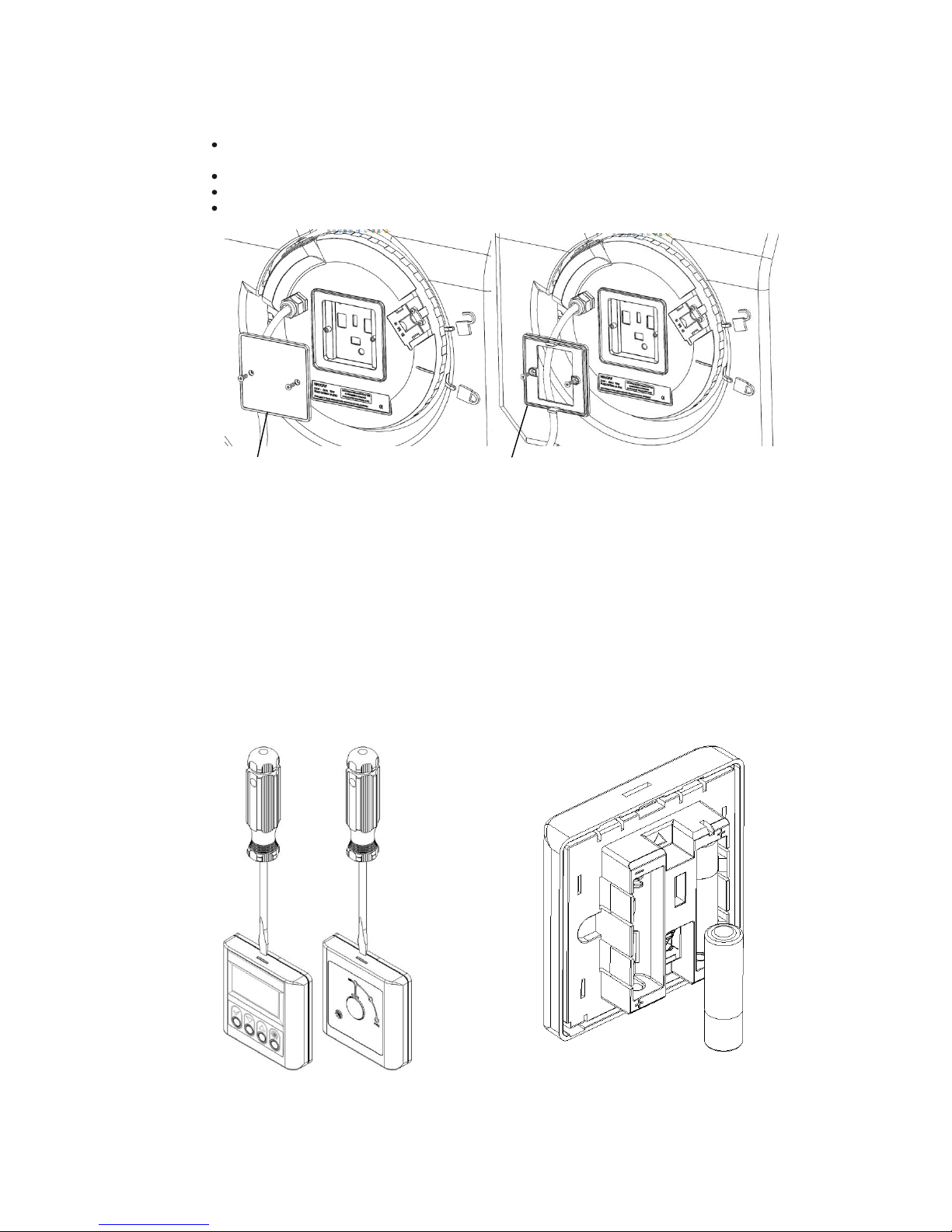
2.3.8
2.3.9
Unit Mounting for GRF1 only (See Figure 11 & 12)
Remove the ‘access for controls pairing’ panel (See Figure 11) located on the flying lead side of the
HRV2HT revealing the docking connector.
Using the original two screws, mount the fixing plate (See Figure 12) to the unit.
Remove any batteries from the controller
Place the GRF1 controller onto the fixing plate until the catch clicks into position.
Figure 11 Figure 12
Removal of the GRF1 and GRF2 Front Cover (for battery insertion / replacement)
The fixing clips (located at the top and bottom) hold the controller securely in place. Never attempt to pull
the controller away from the fixing plate without releasing the clips first, otherwise you could cause damage
to the fixing plate or controller.
Using the tip of a flat blade screwdriver, gently push in to free clips before easing off the controller to remove
(See Figure 13). Insert 2 x AA (non-rechargeable) batteries (See Figure 14). To refit the controller ensure
the correct orientation, before clicking the controller back onto the fixing plate, please ensure both clips at
the top and bottom are fully engaged.
Figure 13 – Recessed Image Illustration Figure 14
Fixing Plate
Access for controls
pairing panel
 Loading...