

Greenwood Frontier CX Installation And Operation Manual

Frontier CX Hydronic Furnace
Installation and Operation
SAVE THESE INSTRUCTIONS
READ THIS MANUAL AND KEEP IT NEAR THE FURNACE FOR REFERENCE
© 2013 Greenwood Clean Energy, Inc
For the latest information about your Greenwood Frontier CX refer to www.GreenwoodUSA.com/support.php
V 1.9
All Rights Reserved

This page intentionally left blank


TABLE OF CONTENTS
TABLE OF CONTENTS
TABLEOFCONTENTS................................................................................................................................................1
APPLIANCEIDENTIFICATION.....................................................................................................................................3
SAFETY.....................................................................................................................................................................4
WARNINGSLABEL............................................................................................................................... ...........................4
LABELLOCATIONS..........................................................................................................................................................5
INTRODUCTION........................................................................................................................................................7
.......................................................................................................................................................................................7
HowtheGreenwoodFrontierWorks.............................................................................................................................7
AirFlowthroughtheFurnace........................................................................................................................................8
FluidFlowthroughtheFurnace.....................................................................................................................................9
SPECIFICATIONS.....................................................................................................................................................10
SpecificationsTable......................................................................................................................................................10
GreenwoodFrontierCXSizing......................................................................................................................................10
GreenwoodFrontierCXComponentIdentification......................................................................................................11
.....................................................................................................................................................................................11
INSTALLATIONPREPARATION................................................................................................................................12
InstallationRequirementsChecklist.............................................................................................................................12
1.UnpackandInspecttheFurnace.............................................................................................................................. 13
2.UnloadtheFurnace..................................................................................................................................................14
3.LocatetheFurnace............................................................................................................................... ....................15
MinimumInstallationClearances................................................................................................................................15
4.InstalltheCombustibleFloorHeatShield................................................................................................................16
5.InstalltheChimneyFlue...........................................................................................................................................16
6.PlumbtheFurnace...................................................................................................................................................17
7.WiretheFurnace......................................................................................................................................................17
CHIMNEYINSTALLATION........................................................................................................................................18
ChimneySize................................................................................................................................................................18
ConnectingtoanExistingChimneyFlue......................................................................................................................18
ConnectingtoaNewFactory‐madeChimney..............................................................................................................20
SupplyingMake‐upAir.................................................................................................................................................21
MeasuringandAdjustingtheDraft.............................................................................................................................22
References....................................................................................................................................................................22
PLUMBINGINSTALLATION......................................................................................................................................23
© 2013 Greenwood Clean Energy, Inc All Rights Reserved V1.9 Page 1

TABLE OF CONTENTS
HydronicSystemConfiguration....................................................................................................................................24
FlatPlateHeatExchangers...........................................................................................................................................24
PipingSchematics........................................................................................................................................................25
......................................................................................................................................................................................26
NonstandardInstalls............................................................................................................................... ......................27
FluidTestingandTreatment.........................................................................................................................................28
WIRING..................................................................................................................................................................30
BoilerControlsandWiringConfiguration.....................................................................................................................30
......................................................................................................................................................................................31
PowerOutageandOverheatProtection.......................................................................................................................32
UniversalPowerSupply................................................................................................................................................33
Auto‐startGenerator....................................................................................................................................................33
AuxiliaryWiringforOn‐DemandZones........................................................................................................................33
AuxiliaryWiringforHeatfromaBackupFurnaceorBoiler..........................................................................................34
OPERATINGTHEFRONTIERCX................................................................................................................................35
ControlSystem..............................................................................................................................................................35
SafePractices................................................................................................................................................................36
BuildingYourFirstFire..................................................................................................................................................37
KeyOperatingGuidelines.............................................................................................................................................38
LoadingWoodintotheFirebox.....................................................................................................................................39
WhatWoodtoBurn......................................................................................................................................................40
HeatContentofWoodbySpecies................................................................................................................................41
AshRemoval.................................................................................................................................................................42
MAINTENANCE.......................................................................................................................................................43
SafePractices................................................................................................................................................................43
HeatTransferFluid.......................................................................................................................................................43
HeatExchangerCleaning..............................................................................................................................................44
AnnualShutdownMaintenance...................................................................................................................................45
SystemFlush............................................................................................................................... ..................................45
TROUBLESHOOTING...............................................................................................................................................46
WARRANTY............................................................................................................................................................50
Page 2 © 2013 Greenwood Clean Energy, Inc All Rights Reserved V1.9
APPLIANCE IDENTIFICATION
APPLIANCE IDENTIFICATION
Please fill in the following information for your records. When contacting your dealer for service or warranty
information please have this information available.
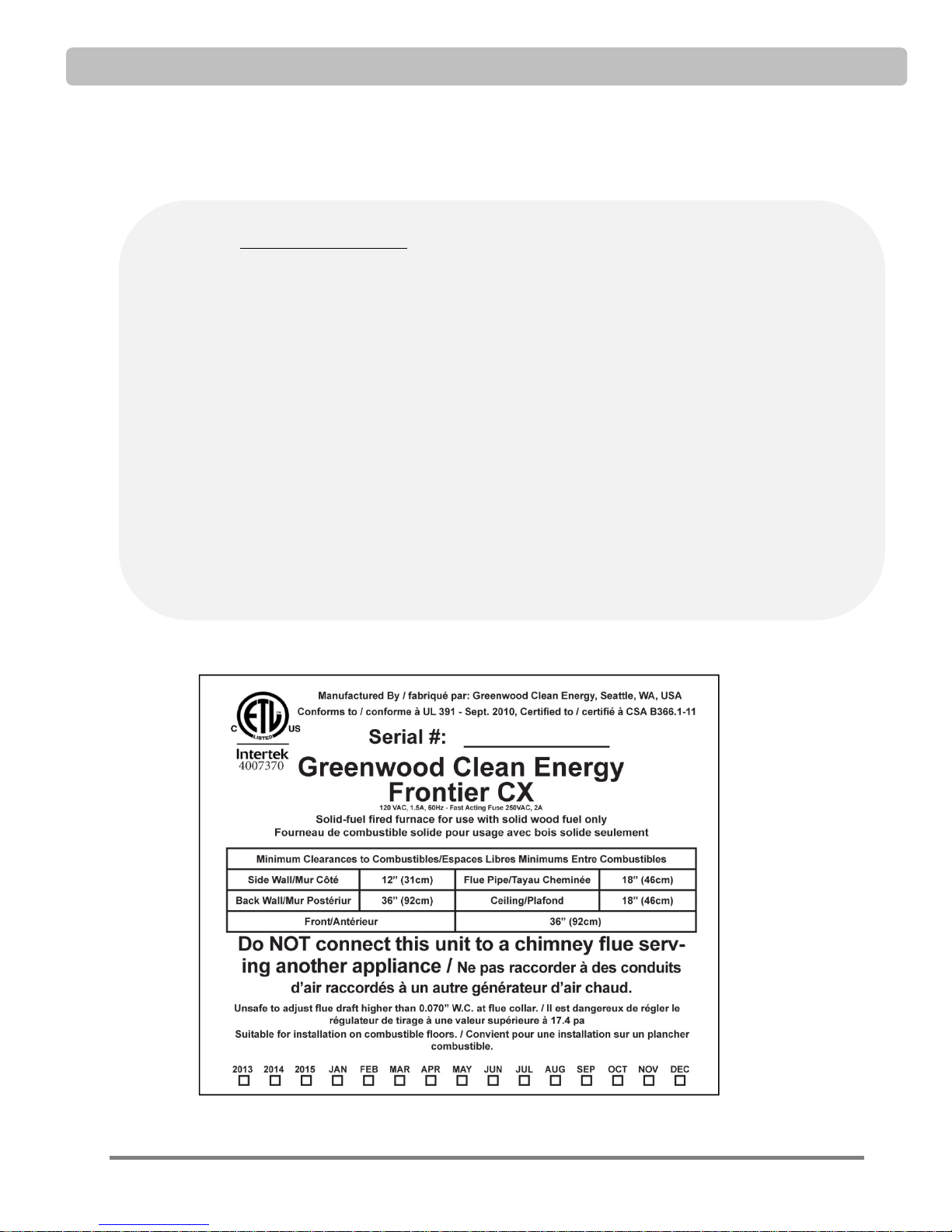
Model: Greenwood Frontier CX Serial No.: GFCXA ___ ___ ___ ___ ___ ___
(To identify your serial number, see nameplate location on page 5.)
Dealer Name: ____________________________________________________________
Address: ________________________________________________________________
Phone: _____________________________
Installer Name: ___________________________________________________________
Address: _________________________________________________________________
Phone: _____________________________
Installation Date: _________________________________________________________
© 2013 Greenwood Clean Energy, Inc All Rights Reserved V1.9 Page 3

SAFETY
WARNINGS LABEL
SAFETY
Page 4 © 2013 Greenwood Clean Energy, Inc All Rights Reserved V1.9
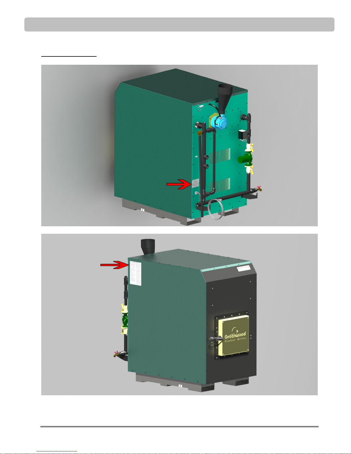
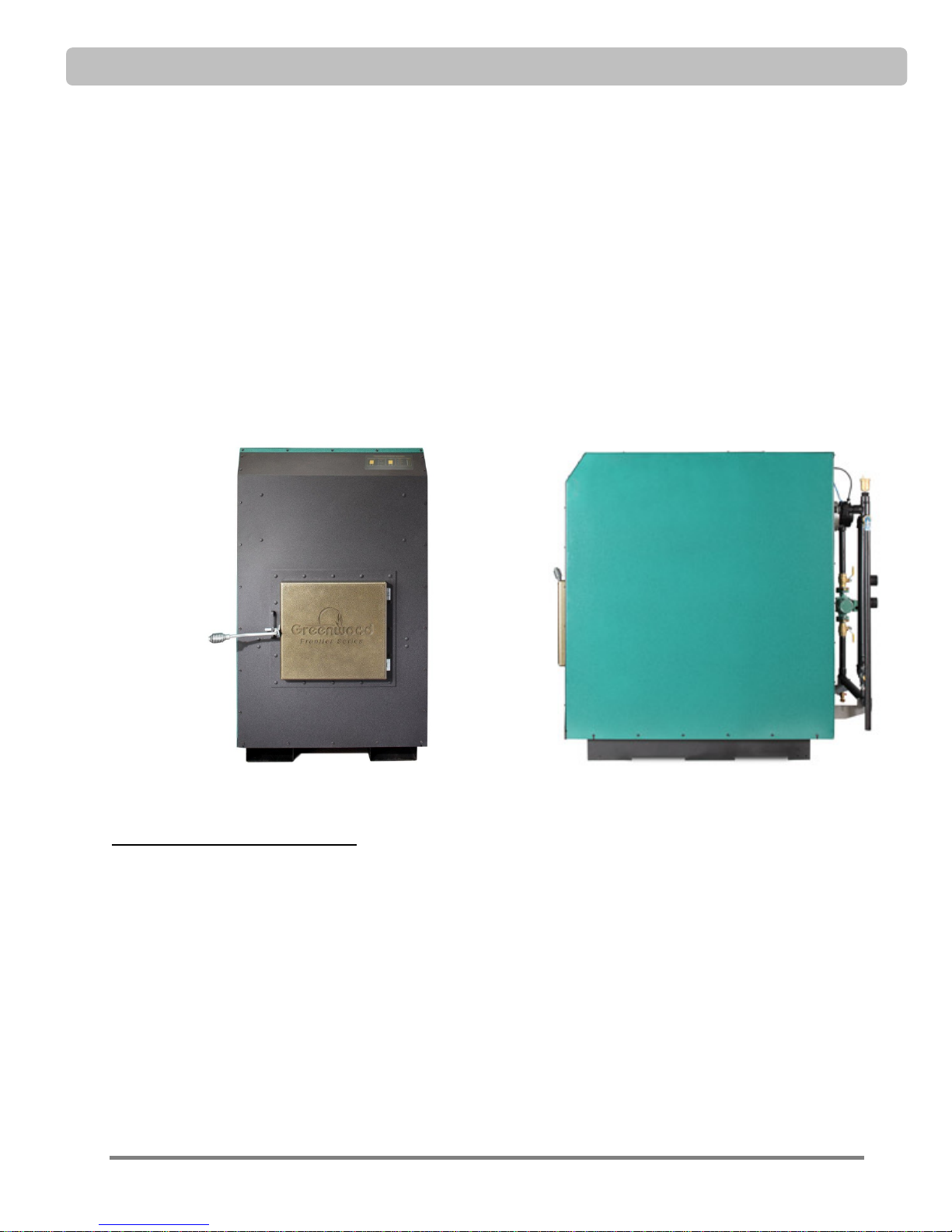
LABEL LOCATIONS
SAFETY
© 2013 Greenwood Clean Energy, Inc All Rights Reserved V1.9 Page 5

SAFETY
This page intentionally left blank
Page 6 © 2013 Greenwood Clean Energy, Inc All Rights Reserved V1.9
INTRODUCTION
INTRODUCTION
Congratulations on your purchase of this Greenwood Frontier Series (“Frontier Series”) wood-fired hydronic
furnace from Greenwood Clean Energy. With proper installation and maintenance, this furnace will provide
years of low cost heat for your home.
To insure correct installation and safe operation of your Greenwood Frontier hydronic furnace, you should:
1. Hire a Greenwood approved licensed heating contractor to install the furnace and integrate it
with your heating system. This contractor should have experience with installation and operation of
hydronic gas, oil, and solid fuel heating appliances and be familiar with local building codes, fire
codes and other regulations.
2. Read this manual and learn how to safely operate and maintain your Frontier Series.
How the Greenwood Frontier Works
The Frontier Series produces low emissions and achieves a high level of heating efficiency. The ceramic
firebox supports an internal temperature and gasification process that converts every bit of wood fuel into
thermal energy. Then, maximum energy is transferred from the superheated air to fluid circulating through
the air-to-water heat exchanger. This simple, yet sophisticated design results in a highly efficient, clean
burning furnace that will provide years of reliable, low cost heating.
To understand how the Frontier Series hydronic furnace works, let’s look at the flow of air and wood gases
through the furnace and the transfer of heat from the superheated gases to the thermal transfer fluid.
© 2013 Greenwood Clean Energy, Inc All Rights Reserved V1.9 Page 7
INTRODUCTION
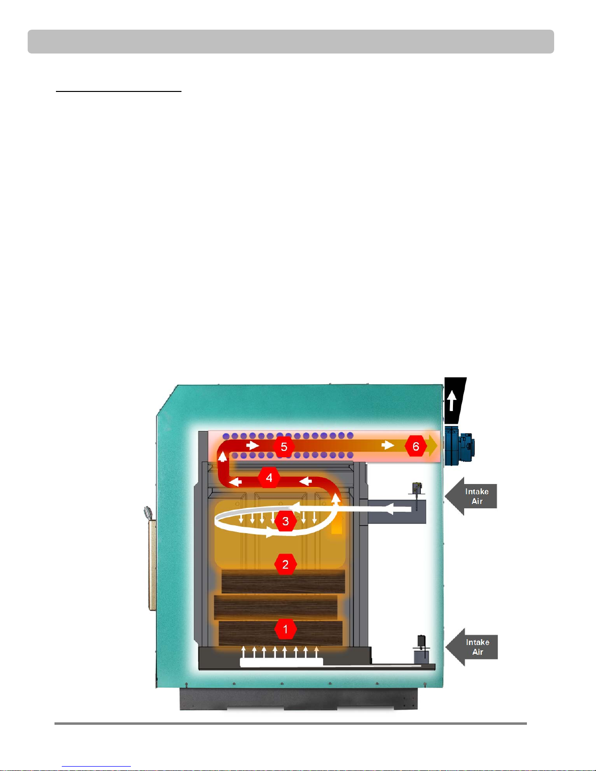
Air Flow through the Furnace
1. Under-Fire Zone: Under-fire air entering through the pinhole grate combined with heat drives the
rate of pyrolysis (the release of gases from the wood fuel).
2. Combustion Zone: 750 lbs (340 kg) of refractory reflect energy back into combustion chamber
maintaining optimum combustion temperatures.
3. Crossfire Zone: Over-fire air is added following the separation of gases from the wood pile.
4. Burn-Out Zone: Combustion is completed in the burn-out zone where gas temperatures reach 2000
o
F (1100 oC).
5. Heat Transfer Zone: Heat is transferred from the hot combustion gasses to the water-tube heat
exchanger in an isolated chamber. This is the only area where heat is transferred to water.
6. Exhaust Zone: Exhaust gases leave the boiler at temperatures of 200 – 450
depending on firing rate.
Side View of Air Flow through the Frontier CX
o
F (93 oC to 205 oC)
Page 8 © 2013 Greenwood Clean Energy, Inc All Rights Reserved V1.9
INTRODUCTION
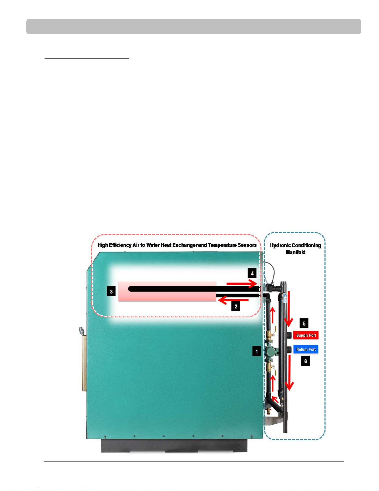
Fluid Flow through the Furnace
The Frontier Series uses a mixture of water, boiler treatment and optional propylene glycol as a heat transfer
fluid. Propylene glycol is a non-toxic solution that prevents the fluid from freezing. The heat transfer fluid
flows through the system as follows:
1. The circulator pushes fluid around the boiler loop.
2. Fluid temperature is monitored by the Greenwood Boiler Management System. The intelligent
control adjusts the burn rate of the furnace, balancing a clean burn heat demand.
3. Fluid passing through the internal heat exchange manifold is heated by the exiting combustion
gasses.
TM
4. The heated fluid enters the Frontier CX Hydronic Conditioning Manifold
temperatures are optimized. (See ‘Plumbing Installation’ section for complete description.)
5. The fluid enters your home heating system through the Supply Port, distributing heat to your home,
garage, basement, pool, and domestic hot water.
6. Having transferred the heat to the home system, the fluid returns through the Return Port and
repeats its path through the Hydronic Conditioning Manifold and internal heat exchanger.
where flows and
Side View of Fluid Flow through the Frontier Series
© 2013 Greenwood Clean Energy, Inc All Rights Reserved V1.9 Page 9
SPECIFICATIONS
SPECIFICATIONS
Specifications Table
Frontier CX Specifications
Operating Range 30 – 85 BTU 8.8 – 22.0 KWH
Peak Output* 110 MBTU 32.24 KWH
Furnace Dimensions
Max log length 21 inches 54cm
Max log diameter 14 inches 35cm
Approximate Weight 1,480 pounds 672.7kg
Firebox Volume
*Heating capacity depends on many factors including home design, construction quality, insulation quality, local climate, type of
wood burned, etc. Square footage based sizing is unreliable, always base sizing on sustained output and heat loss calculations.
32” (w) x 54.5”h (h) x 48” (d)
19” (w) x 32” (h) x 24” (d)
8.4 cubic feet
81.3cm (w) x 138.4 cm (h) x 121.9cm (d)
48.3cm (w) x 81.3cm (h) x 71cm (d)
0.24 cubic meters
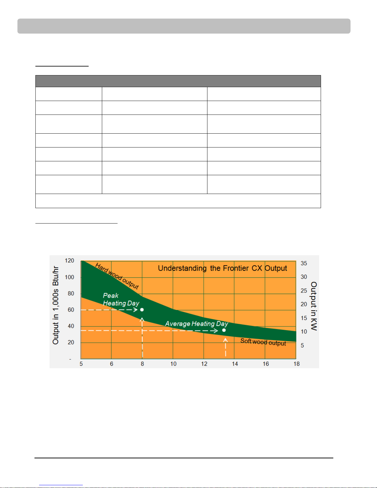
Greenwood Frontier CX Sizing
The Frontier Series CX boiler is designed to be used in a wide variety of heating situations. The Boiler
Sizing chart provides insight into how output varies based on reload frequency.
Actual delivered BTU output and burn time will vary based on the installation and the amount, type and
moisture content of the wood fuel.
Example: An average 2,750sf home in the northeast United States has a peak heat load of 60,000 BTU/hr
(17 kW). On these days the boiler will need reloading every 8 hours. On average winter days (35,000
BTU/hr, 10kW), the boiler requires reloading approximately every 12 hours.
Page 10 © 2013 Greenwood Clean Energy, Inc All Rights Reserved V1.9
Hours Between reload
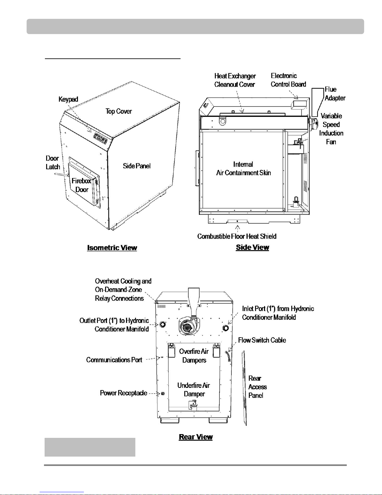
Greenwood Frontier CX Component Identification
SPECIFICATIONS
See Piping Section for piping
component identification
© 2013 Greenwood Clean Energy, Inc All Rights Reserved V1.9 Page 11

INSTALLATION PREPARATION
INSTALLATION PREPARATION
Installation Requirements Checklist
Your Frontier Series should be installed by a Greenwood approved heating contractor who is thoroughly
familiar with gas, oil, and solid fuel hydronic heating appliances. Also, be sure to comply with local building
codes, fire codes and other regulations when installing the hydronic furnace.
These are guidelines; please refer to appropriate manual sections for further details:
Thoroughly read this entire manual and follow all instructions.
Hire a licensed contractor with certified Greenwood installer training and experience in design and
installation of hand-fired hydronic heating systems to install your Frontier Series hydronic furnace.
Use caution when moving this furnace. The Frontier Series hydronic furnace weighs about 1,500 lbs
(680 kg) and serious injury can occur if you do not have the proper equipment and experienced
manpower available.
Comply with local building codes, fire codes and other regulations when installing this furnace and
adhere to minimum clearances and restrictions.
DO NOT install the Frontier Series furnace in a mobile home or trailer. Instead, install the furnace
outside in a fully enclosed structure and pipe the hot water into the mobile home.
Chimney and Venting
Make sure to identify sources of make-up air in the room where the furnace is located. The Frontier
Series furnace, exhaust fans and other appliances all draw air from the room. Be certain there is an
adequate source of fresh air to offset these demands or you may create negative pressure in the room
and starve the furnace of air needed for combustion resulting in poor burn performance and draft
problems in your flue. Make sure that air entering the furnace is above 40°F (4.5°C).
Connect the Frontier Series furnace to a properly installed and operating chimney which is vented to
the outside. Use an approved masonry or a UL 103 HT and ULC S629 Listed Residential Type and
Building Heating Appliance Chimney (double or triple wall insulated flues).
DO NOT vent the furnace to another room or inside a building. Install with a dedicated chimney
only. DO NOT share the chimney with another appliance. Be sure your chimney is safely
constructed and in good repair. Before furnace installation, have the chimney inspected by a
qualified inspector. DO NOT connect the furnace to an aluminum Type B gas vent.
As with any furnace operated indoors, install a carbon monoxide monitor and take any other safety
precautions to maintain safe oxygen levels in the room where the furnace is installed.
Plumbing and Controls
The Frontier Series hydronic furnace is managed by an onboard controller (see “Operating the
Furnace, Control Panel”). Once the hydronic plumbing and chimney are in place per your
installation the unit is ready to plug into a surge protected outlet and start heating your application.
This hydronic furnace is designed to protect itself from low water temperature returns. This prevents
condensation within the boiler which will lead to poor performance and ultimately damage. Make
sure that the unit’s piping conforms to required specifications.
Page 12 © 2013 Greenwood Clean Energy, Inc All Rights Reserved V1.9
INSTALLATION PREPARATION
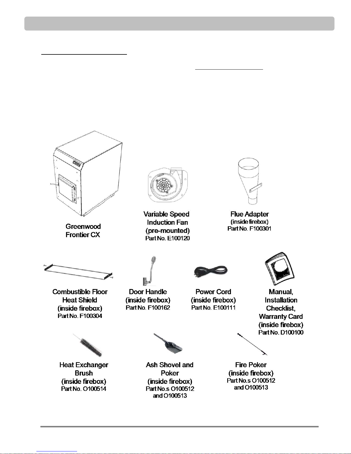
1. Unpack and Inspect the Furnace
When the furnace is delivered, inspect it for visible damage BEFORE the driver leaves. If damaged, list the
issues and date on the shipping document and ask the driver to sign it. Check the packing slip for a list of
items shipped with the furnace (some of the items will be found stowed inside the firebox). If you observe
any damage or find any items missing, please contact your Greenwood Dealer.
Each unit is wired for 115 volt operation. Items shipped with the product include:
© 2013 Greenwood Clean Energy, Inc All Rights Reserved V1.9 Page 13
INSTALLATION PREPARATION
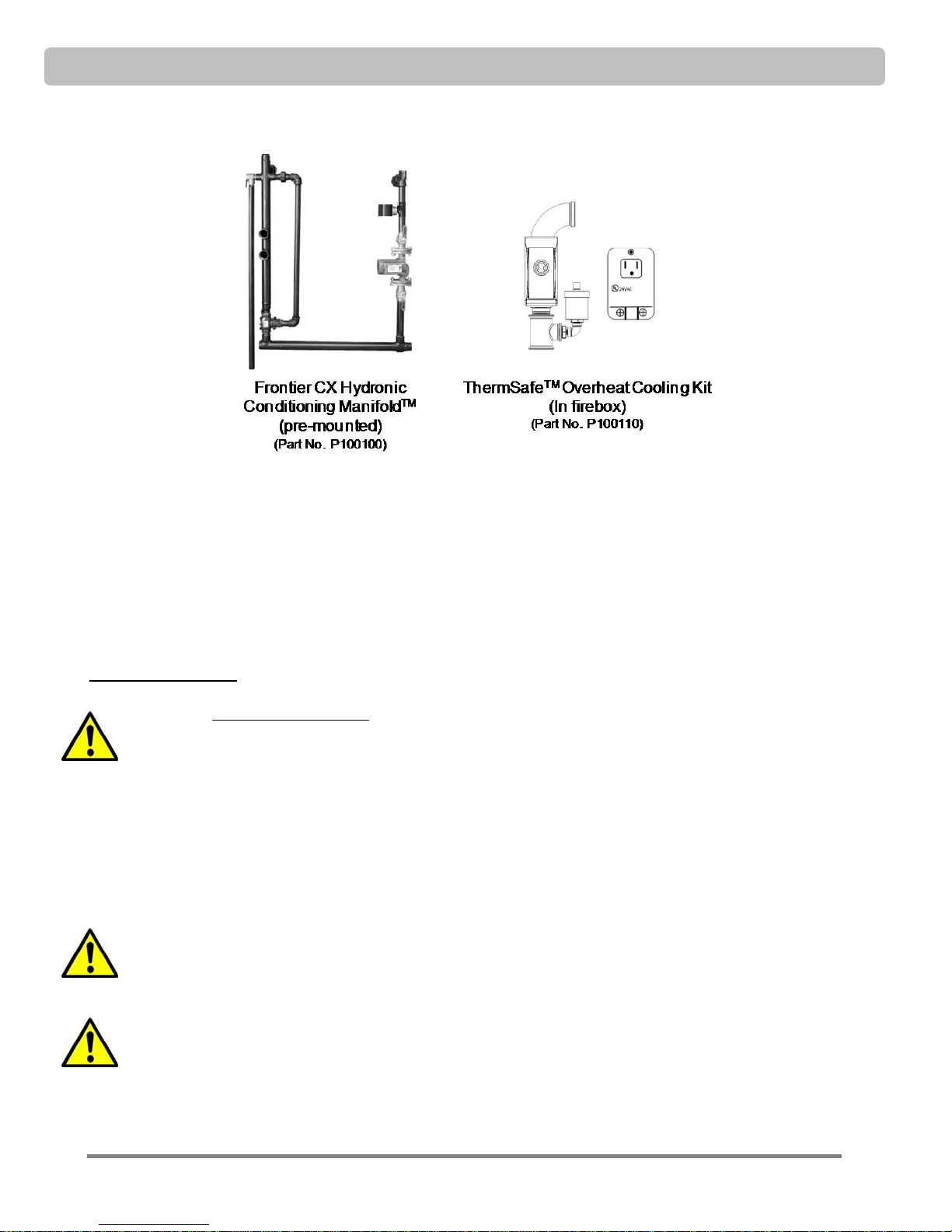
Additional items typically ordered and packaged with the Frontier CX.
Other parts required for your boiler and distribution system installation will be determined by your installer
and may arrive with the furnace or be shipped separately.
Note: These are diagrams of furnace components which are shipped with the unit. Additional parts and
configuration used for installation will be determined by your installer. This diagram does not include
standard installation components such as additional pumps, expa nsion tank and other components
required for integration with your heating system.
2. Unload the Furnace
CAUTION: These units are heavy! The Frontier Series CX weighs about 1,500 pounds (680
kg). Make sure you have proper equipment and sufficient manpower to prevent injury or
damage when unloading and locating the furnace unit.
When moving the furnace, use a forklift with 3,000 lbs (1,360 kg) or greater capacity with 5-6 ft. (152 cm183cm) forks. Center the forks in the lifting channels under the chassis, with the forks spread to minimize
the overhang on either side. Move the loader as close to the furnace as possible without contacting the
furnace with the lifting rack. Pick the furnace up by keeping it level and lifting only as high as necessary to
move the unit. Do not accelerate or stop the loader suddenly. Make slow and stable maneuvers with the
furnace on the forks. The channels under the chassis should not be used to drag or slide the furnace, except
for small adjustments to final placement.
CAUTION: Depending on which side you approach the furnace be aware that the fork lift rack
can damage the plumbing, fan or door handle. Never stand in the path of the load when
lifting or moving the furnace.
WARNING: If you are not a professional rigger or do not have experience with portable
cranes, winches, hoists, or other lifting devices, and you have determined that a top lift is
required to place the furnace in its installed location, you should use an equipment or
machinery-moving company to set the furnace in its final location. If the furnace is dropped,
the refractory ceramic firebox can be damaged. An experienced rigger can ensure that the
furnace is safely lifted and set in place without damage.
Page 14 © 2013 Greenwood Clean Energy, Inc All Rights Reserved V1.9
 Loading...