

Greenwood CMEV-3 Installation Instructions Manual
CMEV-3
Continuous Running Ventilation System
Installation Instructions
1- General Information
1.1CMEV-3 continuous running mechanical extract ventilation system, ensures constant ventilation throughout the home
The MEV system is designed to be installed in reduced spaces, and exhausts the stale air via the extract grilles sited
remotely to the main unit.
The CMEV-3 delivers 30 m
connection.
It is recommended to use passive self-regulating air inlets in the habitable rooms of the dwelling with this apparatus, to
ensure that sufficient replacement air is provided.
1.2 Installation shall be in accordance with the following:
Building Standards (Scotland) (Consolidation) Regulations.
Building Regulations.
Institute of Electrical Engineering (I.E.E) Regulations.
Note: In order to conform to the above regulations, it may be necessary to fit fire dampers or other suitable
devices.
1.3 The Design, Material selection and Installation must only be carried out by competent ventilation engineers.
1.4 Ancillary Equipment
Remote fan speed setting switch; a range of internal / external Grilles, external cowls, ducting.
3
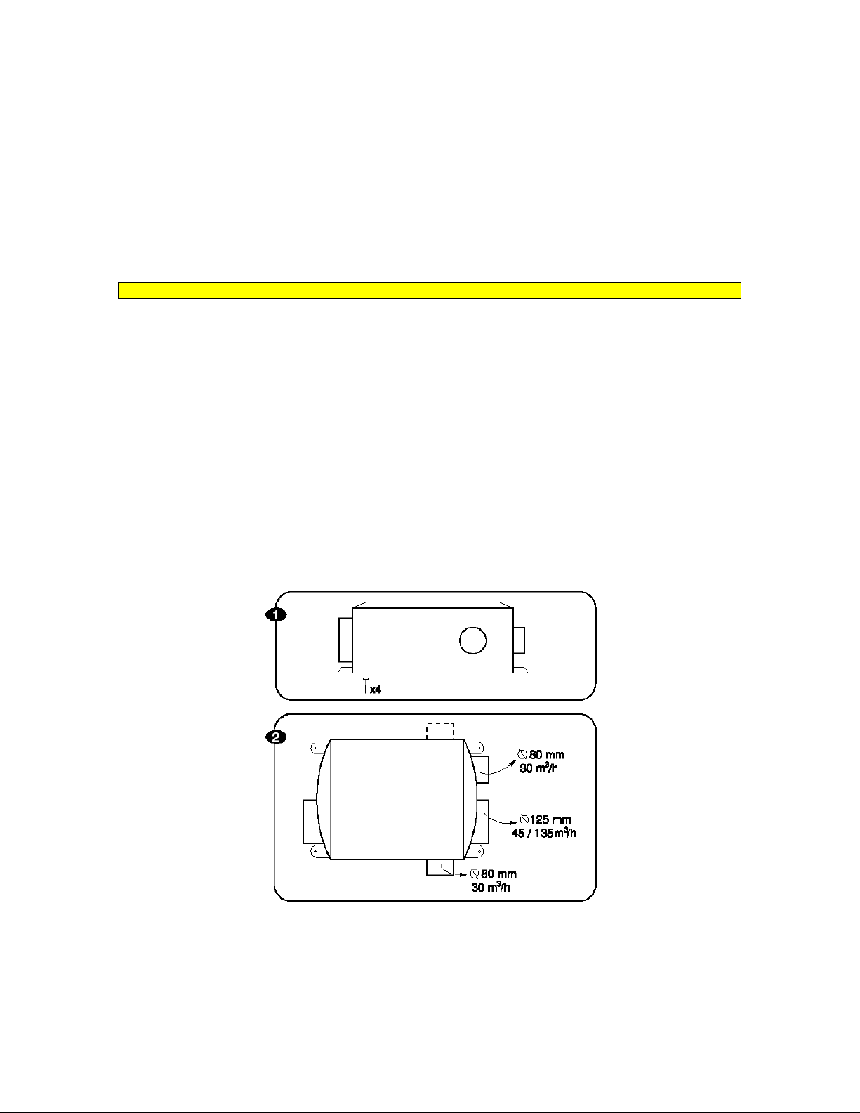
/h through three possible 80 mm connections and one 45 m3/h to 135 m3/h through 125 mm
2 Installations
IMPORTANT: Ensure that flue gasses from fuel-burning equipment are not drawn into a living area. If any room from
which air is extracted contains a fuel burning appliance, such as a central heating boiler, then its flue must be of the room
sealed or balanced flue type, or allowance must be made for an adequate supply of air into the room.
2.1 POSITIONING: (Refer to Fig.1)
2.2 MOUNTING: The unit is supplied with four anti-vibration mountings to provide noise attenuation, through holes to
allow the 4 fixing screw supplied to secure the unit. Make sure the 4 screws are fully secured.
The unit can be mounted in any position to wall, partition or directly to rafters. In the latter case allows for additional cross
support if the distance is greater than the fixing support dimensions.
2.3 Duct and duct connections, (refer to Fig. 1)
2.4 ELECTRICAL: (refer to Fig. 3)
WARNING: THESE APPLIANCES MUST BE EARTHED, AND ALL WIRING MUST BE TO CURRENT I.E.E.
REGULATIONS.
2.1.1 The unit should ideally be installed in the roof space, or, if this is not practical, in a heated area such as
the false ceiling of a WC, airing cupboard etc...
2.1.2 Where possible, the unit should not be installed so that it is directly above a bedroom, living room, or in an
area that is part of a living area or bedroom.
2.1.3 Consideration must be given to access for servicing of the fan.
2.3.1Two 125mm and Three (2 + 1 optional) 80 mm nominal diameter spigots are provided for the connection of
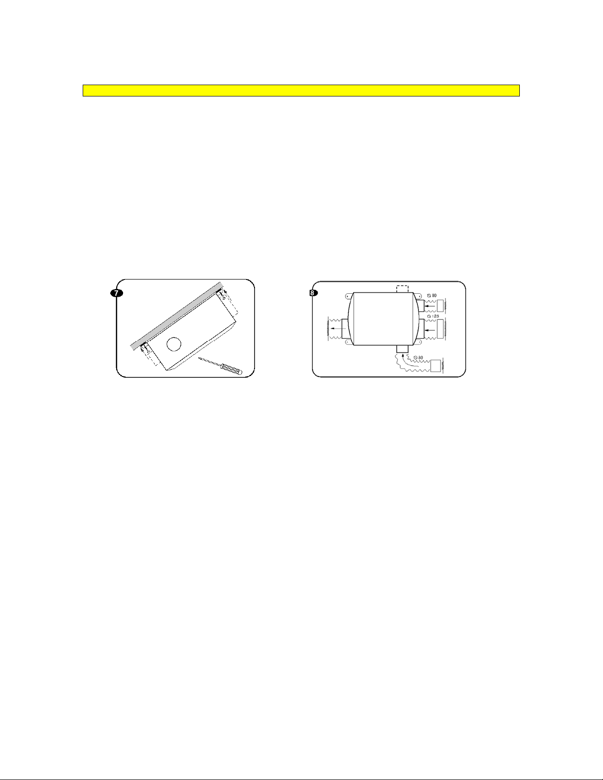
the ducting. These are clearly marked for correct connection of the extract and exhaust ducts. Flexible duct fits
over the spigots and must be secured with correct jubilee clips, whilst rigid duct fits into the spigots.
2.3.2. in applications where there are more than two extract points; a collector box should be connected to the
unit with a short length of flexible duct.
2.3.3 the duct layout must be designed to suit the requirements of the MEV system and building
Layout, and the protection of fire being transmitted through the ducting by means of suitable fire dampers.
2.3.4 Where rigid duct is used, it should be installed using the least number of fittings to minimize the air flow
resistance. Where possible, final connection to the grilles and the unit should be made with a flexible
connection.
2.3.5Where flexible ducts are used, ensure that:
2.3.6 Kitchen extracts must be filtered.
2.4.1 The unit is suitable for a 230V~50Hz single phase supply fused at 3A.
2.4.2 The unit is provided with a terminal strip for connection of the electrical supply cable. The terminals are
clearly marked ‘LIVE’, ‘NEUTRAL’ and ‘EARTH’.
2.4.3 The electrical cable must be 0.75mm2 twin and earth, E.C.C.6242Y to BS 6004, clipped and wired in
accordance with I.E.E. regulations (current edition).
2.4.4 A fused spur box, or double pole switch having a minimum contact separation of 3mm, must be used for
isolation of the unit.
2.4.5 Fan speed is controlled by the fan speed control switch (supplied loose and purpose made to fit a
standard single gang deep socket outlet box,
2.4.6 Location for the switch is remote from the unit, and the control is ideally suited for location in the kitchen
adjacent to the cooker.
a. Lengths of ducting longer than necessary are not used.
b. The duct is pulled taught so that it is smooth and straight.
c. Where bends are necessary, they have large radii - avoid sharp bends.
d. Where duct is run in restricted areas, the duct is not crushed.
 Loading...