

Greenwood AXSK, AXS100SELV, AXS150, AXS125 Installation Instructions And Operators Manual
Warning: The appliance is not intended
for use by young children or infirm persons
unless they have been adequately supervised
by a responsible person to ensure that they
can use the appliance safely. Young children
should be supervised to ensure that they do
not play with the appliance.
l
Observe appropriate safety precautions
if working on steps or ladders. Wear
eye protection when breaking out wall
or window materials etc.
l
Siting Notes:
Where an open-flued oil or gas- fuelled
appliance is installed in the kitchen,
extract ventilation can cause the
spillage of flue gases. Care must be
taken to ensure ventilation is reduced
as appropriate, as set out in the
building regulations. The guide to the
regulations suggests that the reduced
provision should be an extract rate
20 l/s (72 m
3
/h) maximum. Kitchens
with solid-fuel appliances should not
have extract fans fitted.
l
The fans should not be sited where
it would be subject to a direct source
of heat in excess of 40ºC.
l
When installing wall mounted fans,
ensure that there are no buried cables
or pipes in the way. It is recommended
that this fan is mounted 1.8m above
floor level.
l
A clearance of 75mm to be allowed
on at least one side of the fan for
the removal of the internal grille.
l
Cleaning Notes:
Always isolate from the mains before
cleaning. Do not use solvents to clean
the fan. Wipe the front grille clean
using a damp cloth avoiding getting
any water into the internal fan unit.
READ ALL INSTRUCTIONS BEFORE COMMENCING INSTALLATIONS
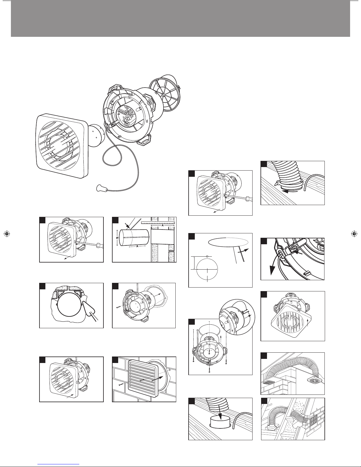
Remove one piece Internal Grille using
screwdriver. Push in to free catch then
twist to remove grille.
Cut the duct to width of the plasterboard
or tiled wall with slight fall to exterior.
(Make provisions for cable).
Using No 8 screws, secure fan body to
ducting first making sure back draught
shutter is fitted, if required, and electrical
cable passes through as appropriate. Wire
fan (See wiring details).
WALL MOUNTING
(Using ED wall duct and EG external grille, 100mm and 150mm only)
1
4
Replace internal grille ensuring no wires
are trapped.
5
Screw the protective wall grille over the
external duct opening.
6
2
AXS100 Ø = 125mm
AXSK/150 Ø = 170mm
Fill in any gaps with mortar or foam and
make good internal and external walls.
Make sure that ducting remains circular
and screw holes are horizontal.
3
CEILING MOUNTING
Remove one piece Internal Grille using
screwdriver. Push in to free catch then
twist to remove grille.
Cut an opening through the ceiling for the
fan and electrical cable.
Place flexible ducting over the spigot of
the fan.
1
4
Fit ducting to spigot using ties supplied,
making sure impeller rotates freely.
Maximum duct length to comply with
Building Regulations:
AXS100: 3m
AXSK/150: Wall mounting only
5
8
X
Ø 12 for cable
X = 67mm for AXS100
X = 78mm for AXS125
Ø = 105mm for AXS100
Ø = 130mm for AXS125
Ø
2
Secure to ceiling using suitable screws
first making sure backdraught shutters
are removed but shutter spider is left in
position. Wire fan (See wiring details).
3
9
6
Detach the cord from the PCB by pulling
the cord through the pull cord’s link.
Installation Instructions for Axial Fans
for Bathroom, Toilets, Utility Rooms and Kitchens
AXS100, AXS100SELV, AXS125, AXS150 & AXSK
Replace internal grille ensuring no wires
are trapped.
7
2
3
1
8
WIRING DETAILS
The electrical connections must be carried out
by a qualified electrician in accordance with
IEE or local regulations.
WARNING: Isolate electricity supply before
starting work.
l
The fans are double insulated and do not
require an earth connection.
l
The fans must be connected to a double
pole isolating switch having contact
separation of at least 3 mm.
l
When supplied from a 6 amp lighting
circuit no local fuse is required.
Specification:
230V~50Hz.
Consumption: AXS100 16W
AXS100SVI 19W
AXS125 28W
AXSK/150 33W
Cable Sizes:
Fixed flat wiring
2 core 1mm
2
3 core 1/1.5mm
2
Flexible round wiring
2 core 0.75mm
2
3 core 0.75mm
2
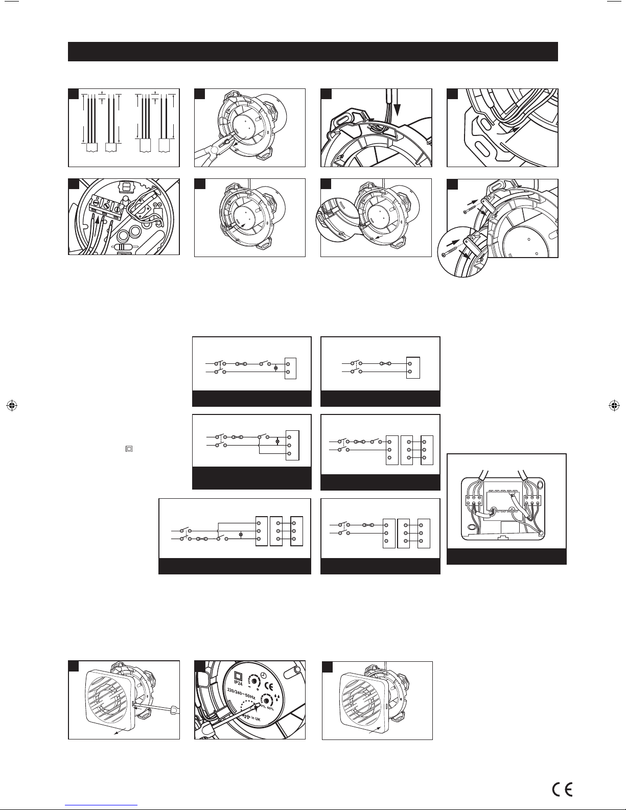
WIRING DIAGRAMS
L
N
Fan
Terminals
L
N
Double pole
isolating switch
Fuse
Light
Remote/Light
Switch
L
N
Fan
Terminals
L
N
Double pole
isolating switch
Fuse
L
N
Fan
Terminals
N
L
Double pole
isolating switch
Fuse
Light
Remote/Light
Switch
June 2010 (MCR499) 05.10.270 Issue 5 BP12895
TO CLEAN OR SERVICE FAN
The only user servicing required with this
fan is the removal and cleaning of the
front grille.
l Remove one piece Internal Grille using
screwdriver. Push in to free catch then
twist to remove grille.
l The fan may now be cleaned using
a brush or damp cloth. DO NOT
IMMERSE IN WATER.
l After cleaning replace Internal Grille
by pushing home.
WARNING: Always isolate fan
from mains supply before cleaning.
Do not use solvents to clean this fan.
Greenwood Air Management Ltd Greenwood House, Brookside Avenue, Rustington, West Sussex, BN16 3LF
Tel: (01903) 771021 Fax: (01903) 782398 Web: www.greenwood.co.uk Email: info@greenwood.co.uk
AXS100, AXS125 & AXS150
L
N
Fan
Terminals
L
N
Double pole
isolating switch
Fuse
L
N
Fan
Terminals
N
L
Double pole
isolating switch
Fuse
L
N
Controller
Terminals
12V Fan
Terminals
N
SL
L
2
3
1
Double pole
isolating switch
1
2
3
Fuse
L
N
Controller
Terminals
12V Fan
Terminals
N
SL
L
2
3
1
Double pole
isolating switch
1
2
3
Fuse
L
N
Fan
Terminals
Light Switch
Switch
Light
Light
Fuse
L1
N
L
Double pole
isolating switch
Remote/Light
Switch
AXS100SVIB
AXS100PC & AXSK
L
N
Fan
Terminals
L
N
Double pole
isolating switch
Fuse
L
N
Fan
Terminals
N
L
Double pole
isolating switch
Fuse
L
N
Fan
Terminals
Light Switch
Light
Light
Fuse
L1
N
L
Double pole
isolating switch
Remote/Light
Switch
AXS100T, AXS100TR, AXS100DT,
AXS100HT, AXS125TR, AXSKMA,
AXS150TR & AXSKT
L
N
Fan
Terminals
L
N
Double pole
isolating switch
Fuse
L
N
Fan
Terminals
N
L
Double pole
isolating switch
Fuse
L
N
Controller
Terminals
12V Fan
Terminals
N
SL
L
2
3
1
Double pole
isolating switch
1
2
3
Fuse
L
N
Controller
Terminals
12V Fan
Terminals
N
SL
L
2
3
1
Double pole
isolating switch
1
2
3
Fuse
Controller
Terminals
12V Fan
Terminals
N
SL
L
2
3
1
1
2
3
L
N
Fan
Terminals
Light Switch
Switch
Light
Light
Fuse
L1
N
L
Double pole
isolating switch
Remote/Light
Switch
L
N
Light Switch
Light (optional)
Fuse
Double pole
isolating switch
SELV Fans External wiring for operation in parallel with
room light or remote switch with or without pull cord
Remove the electrical cover.
Make all connections to the connector blocks.
Note: Mains cable must be fixed back to the
wall using appropriate cable cleats.
Replace electrical cover
Note: Do not fit more than one fan to the
controller or connect with any other product.
This equipment must be sited away from
direct water spray and heat in excess of 40˚C
the controller must not be sited within reach
of a person using a bath or shower nor within
a shower cubicle/enclosure.
Mains
230 V ~ 50 Hz
To Fan 12 V
SELV FANS ONLY
TO WIRE THE CONTROLLER
SVI 12 V Controller
(with switch line)
L
N
Fan
Terminals
L
N
Double pole
isolating switch
Fuse
L
N
Fan
Terminals
N
L
Double pole
isolating switch
Fuse
L
N
Controller
Terminals
12V Fan
Terminals
N
SL
L
2
3
1
Double pole
isolating switch
1
2
3
Fuse
L
N
Fan
Terminals
Light Switch
Light
Light
Fuse
L1
N
L
Double pole
isolating switch
Remote/Light
Switch
SELV Fans
External wiring for pull cord only
2 3
4
5
6 7
Before commencing wiring remove centre
safety cover over PCB using a pair of pliers.
Before replacing centre safety cover, after
wiring, make sure the pull cord link is
located correctly behind the PCB as shown
(inset diagram 5). Refit safety cover on
completion of wiring by pushing home.
Note: If cable is supplied with earth core
this can be cut to the same length and
‘parked’ as shown in diagram 7.
If fixed flat cable is used or flexible cable
which is secured with suitable wall fixings
the cable clamp is not required.
If flexible cable is used without suitable
fixings use cable clamp and screw supplied
loose with the fan (diagram 8).
For SELV fans only
Maximum cable length between fan and
controller:
Conductor Size Maximum length
0.75mm
2
2.3m
1.00mm
2
3.0m
SENSOR/TIMER ADJUSTMENTS
Note: Isolate from mains before commencing
work/adjusting timer.
The removal of the wiring cover and setting of
temperature and humidity controls may only
be carried out by a Qualified Electrician in
accordance with local regulations.
1 Remove one piece Internal Grille using
screwdriver. Push in to free catch then
twist to remove grille.
2 The timer is pre-set but may be adjusted
by using a screwdriver and rotating
clockwise to increase time and anticlockwise to reduce time overrun.
The humidity sensor is pre-set but may
be adjusted by using a screwdriver
and rotating clockwise to increase the
sensitivity and anti-clockwise to reduce
the sensitivity.
4 After adjustments replace Internal Grille
by pushing home.
Installation Instructions for AXS100, AXS100SELV, AXS125, AXS150 & AXSK Axial Fans
115mm
115mm
6mm
100mm
6mm
100mm
1
AXS100
AXSK, AXS125
& AXS150
 Loading...