

GreenWave Reality PowerNode NP222-B, PowerNode NP220-B, PowerNode NS220-B, PowerNode NS222-B User Manual

PowerNodes
NP220-B, NP222-B
NS220-B, NS222-B

Table of Contents
Introduction 1
PowerNode Overview 2
One-Port PowerNode 3
Multi-Port PowerNode 4
Installation 9
Common Z-Wave Tasks 14
Network Inclusion Process 14
Network Exclusion Process 16
Safety Information 18
About GreenWave 19
Product Specifications 20
The GreenWave Reality platform helps create a smart, energy
controlling of your
appliances and electronics (referred to as
impact to your lifestyle by using our products to easily manage your devices. Simply connect our Gateway to
GreenWave Reality energy management system
and control the devices’ power usage through a Web browser or
efficient home through the monitoring and
. You can conserve energy with minimal
, plug your devices into our PowerNodes, and then mo
Introduction
-
“devices”)
your
nitor
smartphone application.
1
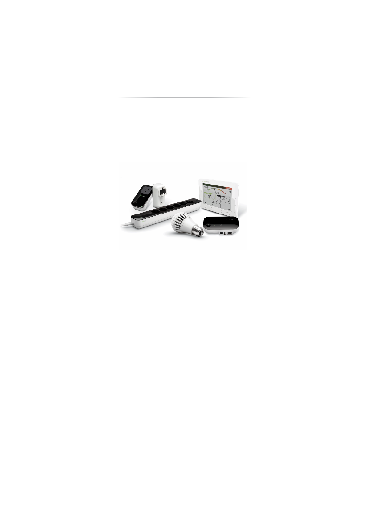
PowerNode Overview
The GreenWave Reality PowerNode is a smart outlet adapter that connects your
energy man
usage remotely through a Web browser or
The PowerNode automatically connects to your Green
home network). This connection enables the Gateway to securely
connect the devices you have powered through your PowerNode to
. The PowerNode collects data on
the energy consumption of the connected devices and transmits the
data to the Gateway. You can then control the energy consumption
of each connected device automatically using GreenWave Reality
fined Smart Controls allow you to turn
devices on or off remotely through a Web browser or
or to set a schedule for automatically turning your devices
to electrical outlets and
so that you can monitor and control your devices’ power
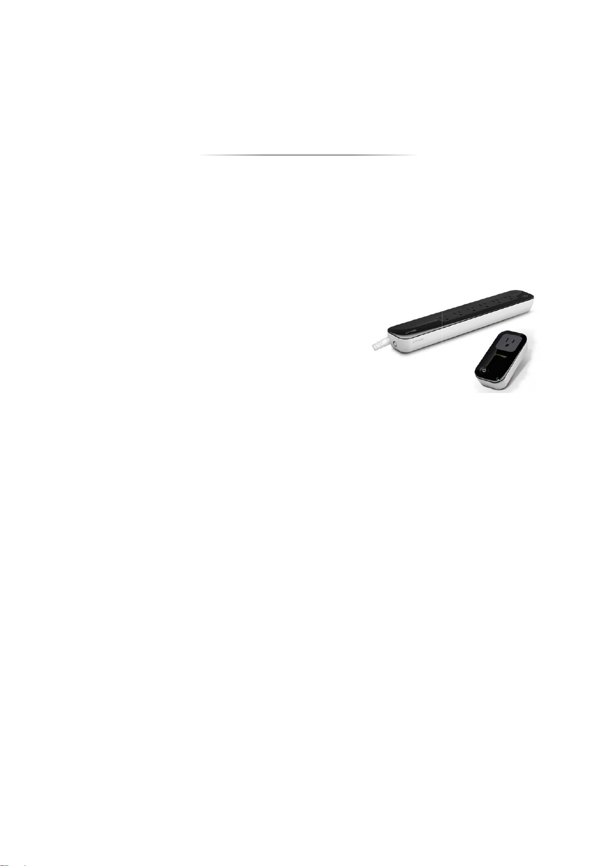
PowerNodes are available with a one
Wave Reality Gateway (the device that connects to your
your GreenWave Reality
multi-port configuration.
your energy management system
agement system
smartphone application.
devices
-port or
Smart Controls. These user-de
application
on or off at pre-defined times.
2
smartphone
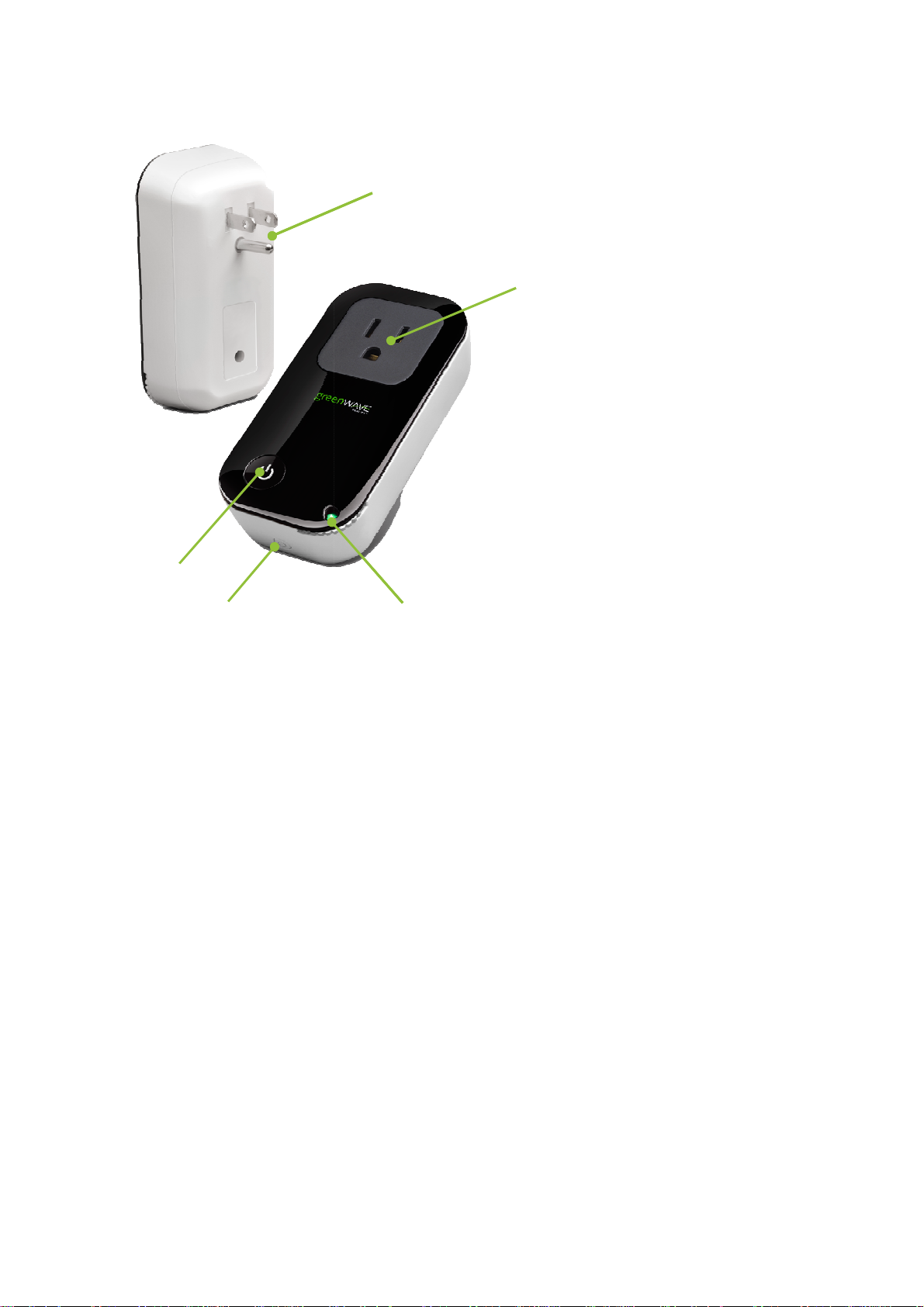
One-Port PowerNode
PowerNode plug
electrical
PowerNode
your device.
Room color selector
specify the associated room
button
sync PowerNode with Gateway
process call
Activity indicator and power on/off
button. Shows the status of synced
devices, and allows you to manually
turn the PowerNode ports on or off.
port PowerNodes, the power
button turns on
1.
1
2
into your
2.
in
3.
rotate to
color.
4. Sync
5.
multi-
: Prongs that you plug
outlet.
socket: Port where you plug
: Wheel that you
: Button that you press to
(a
ed “inclusion”).
For
or off all ports.
5
4
3
3
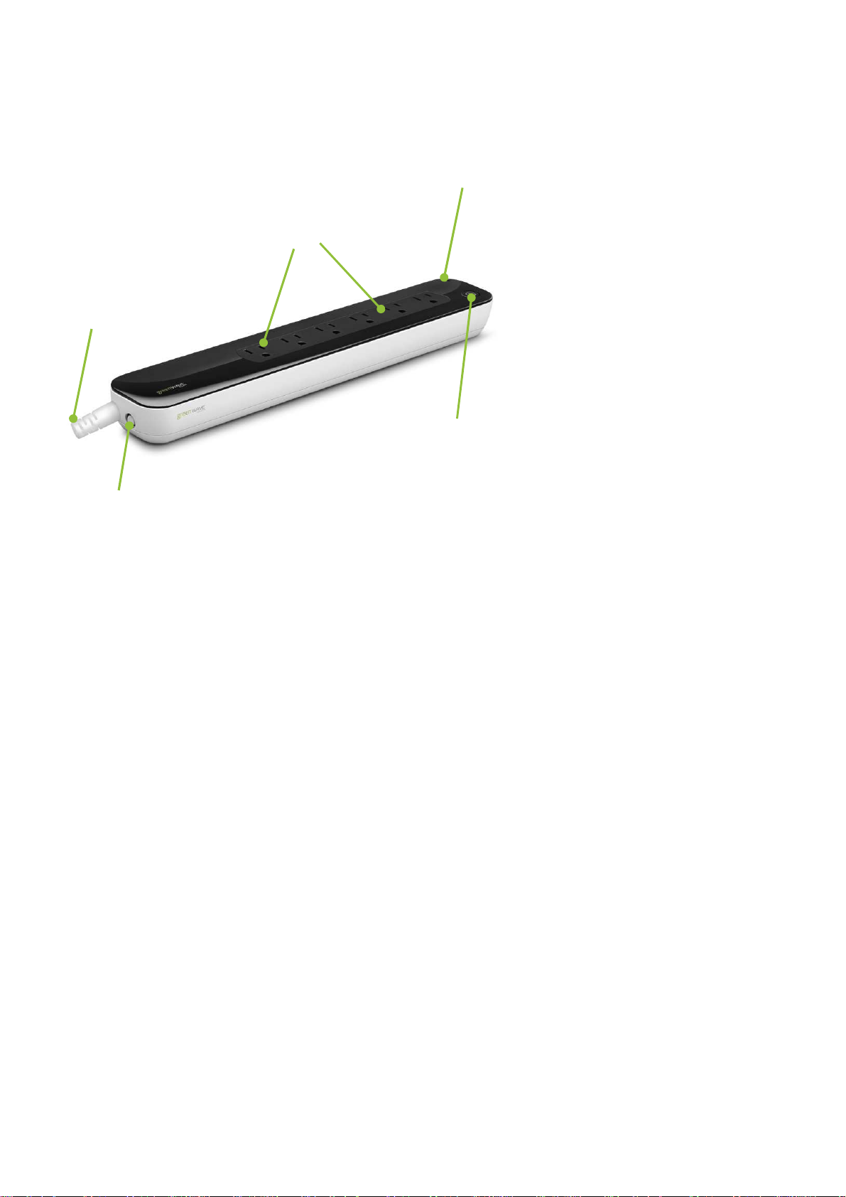
Multi-Port PowerNode
1
3
2
4
1. PowerNode power cord: Power cord
that you plug into your electrical outlet.
2. PowerNode sockets: Ports where you
plug in your devices.
3. Room color selector: Wheel that you
rotate to specify the associated room
color.
4. Activity indicator and power on/off
button. Shows the status of synced
devices, and allows you to manually
turn the PowerNode ports on or off. For
multi-port PowerNodes, the power
button turns on or off all ports.
5. Sync button: Button that you press to
sync PowerNode with Gateway (a
process called “inclusion”).
5
4

Room Colors
Your PowerNode has a corner wheel with colored numbers to
represent the room or device that the PowerNode is powering. Set
the PowerNode to the colored number you want to use to identify
the room or device (this is referred to as the “room color”). For
example, you can set the room color to blue. Then, when you
access your account through the Web or smartphone application,
the corresponding room is identified by the same blue color as your
PowerNode.
You can set PowerNodes in different rooms to different colors to
make those rooms easy to identify when managing the power
sources on the Web or smartphone application.
Special Wheel Colors
The PowerNode includes unnumbered white and black wheel colors that each serve a special purpose. The
white wheel color (which also contains a lock icon) is the locked position. Setting a PowerNode to white enables
monitoring but disables power management. You can monitor energy use information for devices plugged into a
PowerNode using the white wheel color, but you cannot power those devices on or off remotely (for example,
through Smart Controls). White is suggested for appliances such as refrigerators or medical equipment.
The black wheel color allows you to manage the connected devices without assigning them to a specific colored
number. All devices that you have plugged into a PowerNode using the black wheel color will be included under
5

one generic grouping when you access your account through the Web or smartphone application. You can still
monitor the devices’ energy use information and use them with Smart Controls as if they were categorized under
a standard wheel color. The only difference is the manner in which they are grouped under your account.
6
 Loading...