

Page 1

PowerNodes
NP160-F
NP162-F
Page 2

Table of Contents
Introduction 1!
PowerNode Overview 2!
Installation 6!
Common Z-Wave Tasks 10!
Network Inclusion Process 10!
Network Exclusion Process 11!
Factory Reset Process 13!
Safety Information 14!
About GreenWave 16!
Page 3
1
Introduction
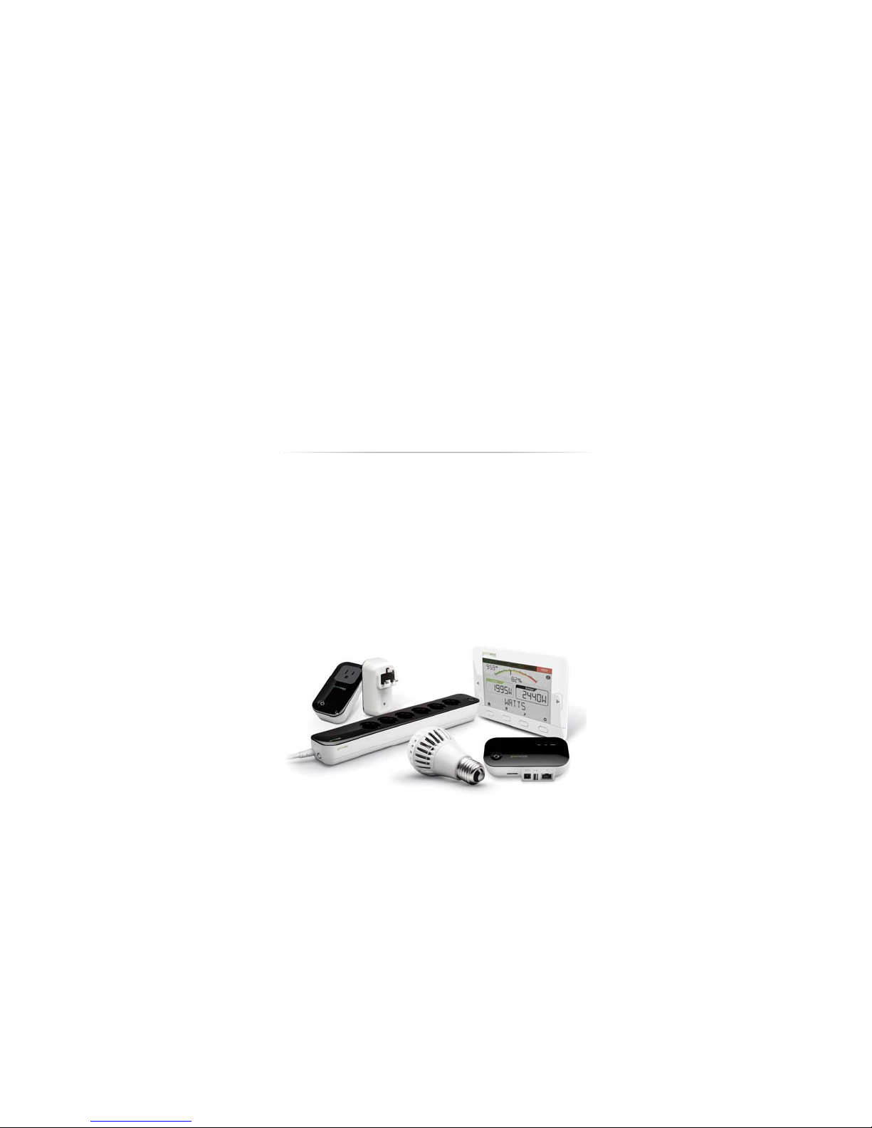
The GreenWave Reality platform helps create a smart, energy-efficient home through the monitoring and
controlling of your appliances and electronics (referred to as “devices”). You can conserve energy with minimal
impact to your lifestyle by using our products to easily manage your devices. Simply connect our Gateway to
your GreenWave Reality energy management system, plug your devices into our PowerNodes, and then monitor
and control the devices’ power usage through a Web browser or smartphone application.
Page 4

PowerNode Overview
The GreenWave Reality PowerNode is a smart outlet adapter that connects your devices to electrical outlets and
your GreenWave Reality energy management system so that you can monitor and control your devices’ power
usage remotely through a Web browser or smartphone application. PowerNodes are available with a one-port or
multi-port configuration.
The PowerNode automatically connects to your GreenWave Reality Gateway (the device that connects to your
home network). This connection enables the Gateway to securely connect the devices you have powered
through your PowerNode to your energy management system. The PowerNode collects data on the energy
consumption of the connected devices and transmits the data to the Gateway. You can then control the energy
consumption of each connected device automatically using GreenWave Reality Smart Controls. These user-
defined Smart Controls allow you to turn devices on or off remotely through a Web browser or smartphone
application or to set a schedule for automatically turning your devices on or off at pre-defined times.
Page 5
3
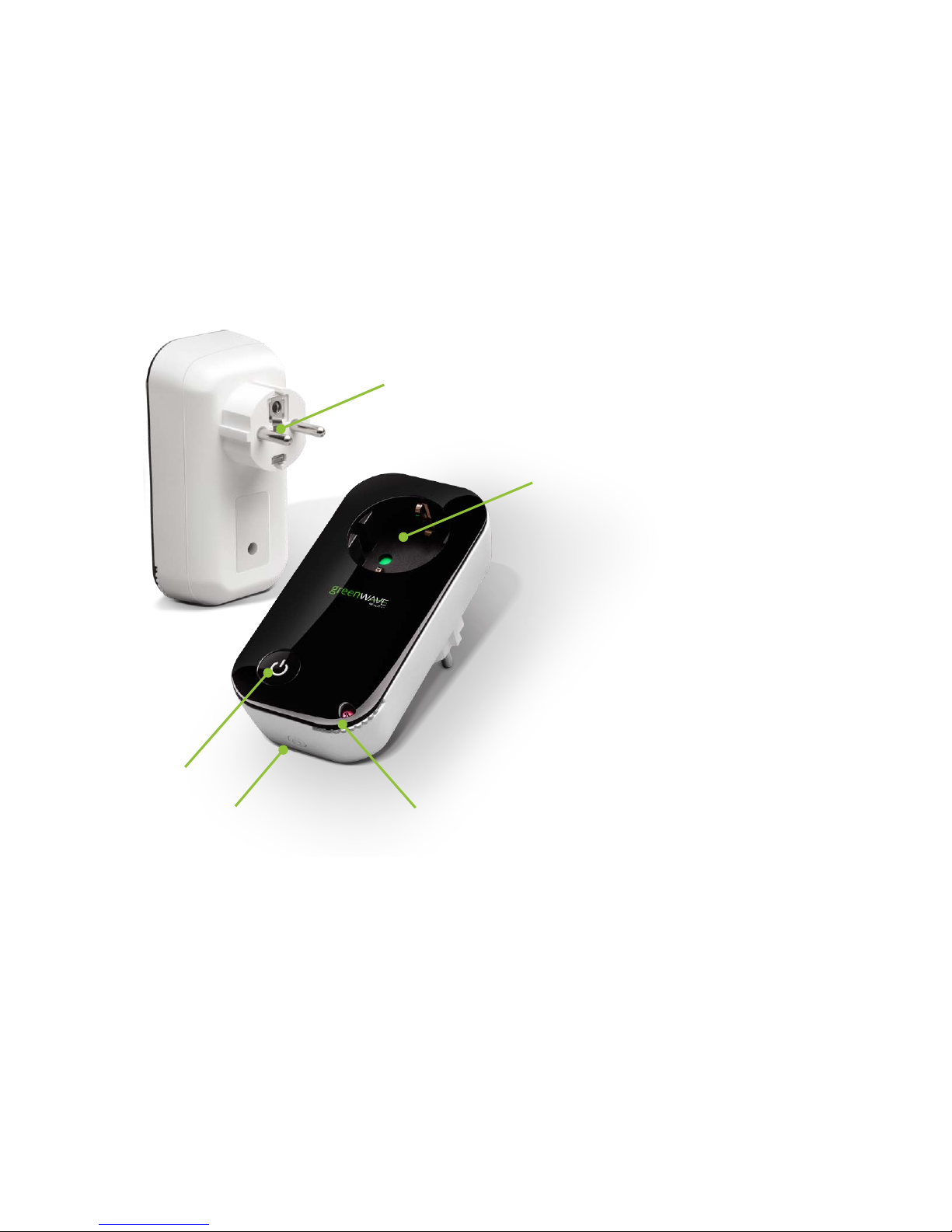
1. PowerNode plug: Prongs that you plug
into your electrical outlet.
2. PowerNode port: Port where you plug in
your device.
3. Room color selector: Wheel that you
rotate you specify the associated room
color.
4. Network button: Button that you press to
sync PowerNode with Gateway.
5. Activity indicator and power on/off
button. Shows the status of synced
devices, and allows you to manually
turn the PowerNode ports on or off.
5 1 2 3 4
Page 6
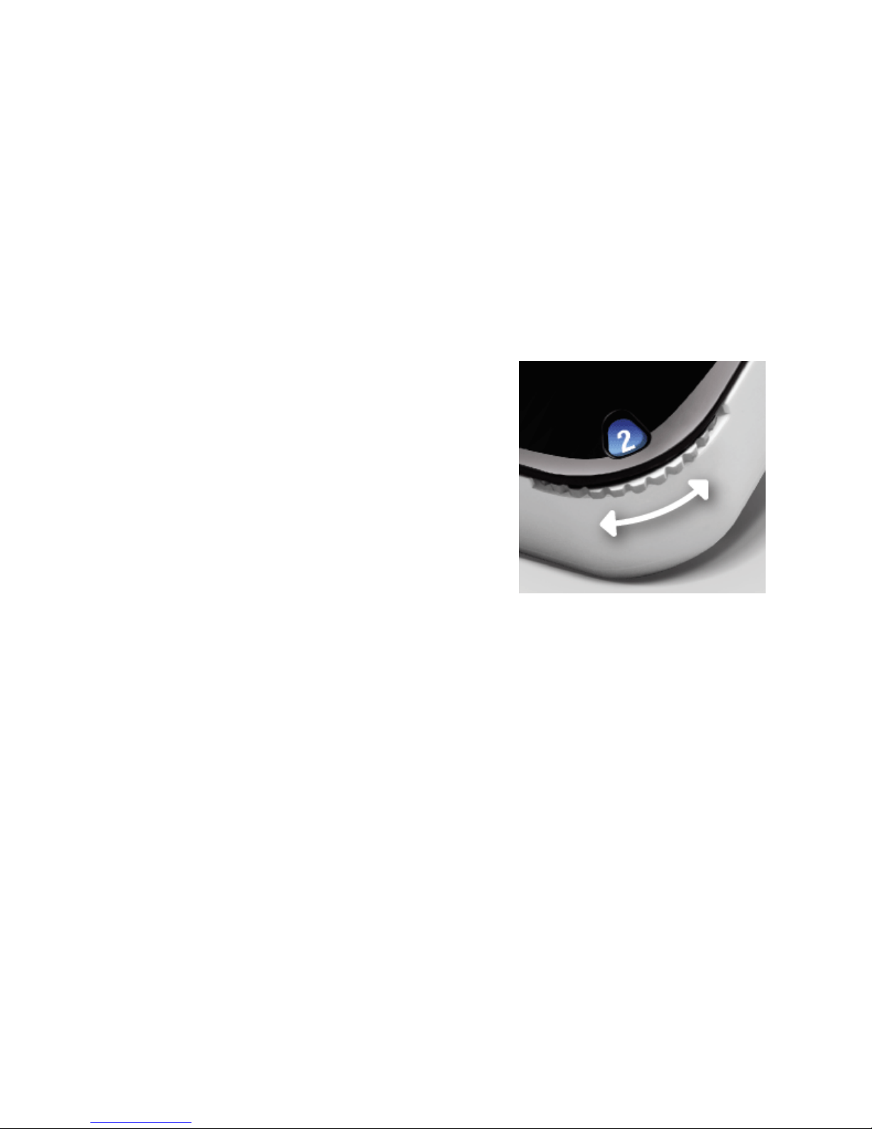
Room Colors
Your PowerNode has a corner wheel with colored numbers to
represent the room or device that the PowerNode is powering. Set
the PowerNode to the colored number you want to use to identify
the room or device (this is referred to as the “room color”). For
example, you can set the room color to blue. Then, when you
access your account through the Web or smartphone application,
the corresponding room is identified by the same blue color as your
PowerNode.
You can set PowerNodes in different rooms to different colors to
make those rooms easy to identify when managing the power
sources on the Web or smartphone application.
Page 7

5
Indicators
Your PowerNode has an indicator that displays any of the following patterns and colors to show you its current
status:
Off (no color): All PowerNode ports connected to
the Gateway are off.
Steady white in center: All PowerNode ports
connected to the Gateway are on.
Steady green in center: Some PowerNode ports
connected to the Gateway are on (some are off).
Two rotating green bars: PowerNode
is in inclusion mode to connect with
Gateway. When inclusion is
successful, the rotating bars stop and
all bars turn green for five seconds.
Two flashing green bars on each side of white flashing
center: PowerNode cannot communicate with Gateway.
This may occur if the PowerNode is out of range from the
Gateway. You can move the PowerNode closer to the
Gateway to improve reception. Or you can add additional
PowerNodes closer to the Gateway so that the PowerNode
can connect to the Gateway via the additional PowerNodes
(PowerNodes can “piggy back” on each other’s network
connection).
Page 8

Installation
Before you install your PowerNode and devices, make sure that your GreenWave Reality Gateway is already
connected to your energy management system and operating (refer to the instructions that came with your
Gateway).
There are four basic steps to install your PowerNode and devices:
1. Set the PowerNode room color.
2. Choose the device to connect and its location.
3. Prepare the PowerNode for the device.
4. Plug in the device and turn on the PowerNode.
Page 9

7
1. Set the PowerNode Room Color
Set the PowerNode to the colored number you want to use to identify the room or
device (this is referred to as the “room color”).
The room color selection is strictly to help you identify the room when you monitor
and control its power usage. Any color setting you use will work automatically with
your Gateway. Refer to the section above on room colors.
2. Choose the Device and Location
Choose the device you would like to connect to your PowerNode. Turn the device off and unplug it from any
power source. As discussed in the “Installation Tips” section, you should attach only one device to each
PowerNode port (one device for a single-port PowerNode or up to six devices for a multi-port PowerNode).
Locate a suitable electrical outlet nearby where you would like to place the device.
3. Prepare the PowerNode for the Device
Plug the PowerNode into the electrical outlet, and then turn the PowerNode off by pressing the power button.
The indicator light on the power button turns off to indicate the power is off.
Page 10

4. Plug in the Device and Turn on the PowerNode
Plug the device you want to power into the PowerNode port. Turn the PowerNode on by pressing the power
button, which will illuminate white to indicate the power is on. Turn the device on.
The device is now part of your GreenWave home network.
Installation Tips
Review the safety information. Be sure to review the information contained in the “Safety Information” chapter
for important safety information you should follow.
Connect only one device per PowerNode port. For best results, attach only one device to each PowerNode
port (one device for a single-port PowerNode or up to six devices for a multi-port PowerNode). Do not connect
power strips and extension cords (or other PowerNodes) to the PowerNode. The PowerNode can only reliably
monitor and control one device connected to one port at the time. Connecting more devices to one port interferes
with power consumption monitoring and may cause risk of malfunction and damage to your PowerNode from
overloading. If you would like to control more devices, you can easily add more PowerNodes to your energy
management system.
Keep radio signals clear. Your Gateway and PowerNodes have antennas built-in for radio communication with
Internet services and other devices on your energy management system. Just as you might experience reception
problems on your mobile phone inside a building, your Gateway can have trouble communicating with
Page 11

9
PowerNodes if their radio signals are blocked by obstacles such as large metal panels or walls containing wire
mesh. When placing these devices in your home, imagine invisible lines connecting between them. Try to keep
these lines clear from obstruction as much as possible. Also place your PowerNodes at least 1.5-3 feet (.5-1
meters) above floor level to promote reception.
Page 12

Common Z-Wave Tasks
The GreenWave Reality PowerNodes communicate wirelessly with the Gateway by use of Z-Wave mesh
networking, which is a robust connection technology designed for home automation with security and privacy in
mind. The more Z-Wave compatible devices installed in your home, the better coverage your private GreenWave
Reality energy management system will have.
Network Inclusion Process
The process for adding a PowerNode to your home network is called “inclusion.” It must only be performed once,
and you must have the Gateway plugged in and working first. You can start the inclusion process by pressing
and holding the Gateway network button for two seconds so the rotating “inclusion mode” pattern appears on the
Gateway activity Indicator. When this is completed, the Gateway is ready to perform the inclusion of the
PowerNode.
Page 13

11
If you attempt to include a PowerNode from another energy management system with an “alien” Gateway,
the inclusion will fail and the indicator bars will flash rapidly.
To complete the process you must perform the following steps:
1. Plug the PowerNode into an electrical outlet.
2. Locate the network button on the PowerNode. It is a small round button on the side of the device,
marked with the sync symbol.
3. Press and hold the network button for one second until the PowerNode activity indicator begins to
display a clockwise-rotating pattern, which shows that the PowerNode is attempting inclusion.
4. After a few seconds, the rotating pattern should stop and all bars turn green for five seconds to indicate
successful inclusion. The PowerNode is now part of your energy management system, and you can
connect a device (refer to the instructions that came with your PowerNode to plug in your device).
If the rotating pattern has stopped but the bars rapidly flash green for five seconds, then the PowerNode
inclusion process has failed, and you must start over.
Network Exclusion Process
Note: If your PowerNode is new and has never been used before, then you should not need to perform the
exclusion process.
Page 14

A PowerNode that has been previously used with a different Z-Wave network must have its association (homeID)
with the other network removed before you can connect it to your GreenWave Reality energy management
system. This process is called “exclusion” and requires two steps: one that must be performed with the Gateway
and then one that is performed with the PowerNode.
You can start the exclusion process through your Gateway user interface or by pressing and holding the
Gateway network button for five seconds until the “exclusion mode” pattern appears on the Gateway activity
indicator. When this is completed, the Gateway is ready to perform the exclusion of the PowerNode.
To complete the process you must perform the following steps:
1. Plug the PowerNode into an electrical outlet.
2. Locate the network button on the PowerNode. It is a small round button on the side of the device,
marked with the sync symbol.
3. Press and hold the network button for one second until the PowerNode activity indicator begins to
display a clockwise-rotating pattern, which shows that the PowerNode is attempting exclusion.
4. After a few seconds, the rotating pattern should stop and all bars turn green for five seconds to indicate
successful exclusion. Your PowerNode is now free of its former association, and you can perform an
inclusion process to include it in your GreenWave Reality energy management system (refer to the
“Network Inclusion Process” section above).
If the rotating pattern has stopped but the bars rapidly flash green for five seconds, then the PowerNode
exclusion process has failed, and you must start over.
Page 15

13
Factory Reset Process
The factory reset process allows you to reset your PowerNode to the factory defaults. This action is helpful if you
are not able to perform a successful exclusion from the Gateway or if you simply want to revert back to the
original factory settings. To complete the process you must perform the following steps:
1. Press and hold the power button while plugging the PowerNode into an electrical outlet.
2. Keep the power button pressed for five seconds until all bars turn green for five seconds, indicating that
the factory reset process has completed. Your PowerNode is now free of its former association, and you
can perform an inclusion process to include it in your GreenWave Reality energy management system
(refer to the “Network Inclusion Process” section above).
If all bars did not turn green for five seconds, then the PowerNode was not previously included.
Page 16

Safety Information
Indoor Use Only
Your PowerNode should be used only in dry, indoor locations. Do not use your PowerNode in high-humidity
locations such as greenhouses, saunas, washrooms, or patios. Do not use your PowerNode in locations where it
can get wet such as near aquariums or running water.
Do Not Disassemble
Your PowerNode has no user-serviceable parts inside. In case of persisting malfunction, please contact
Customer Service to arrange for repair at a certified service location. Do not attempt to disassemble the
PowerNode for any reason.
Page 17

15
Arrange for Service if Needed
Should you encounter any problems with your PowerNode, turn the device off by unplugging it from the electrical
outlet. Contact Customer Service to arrange for repair at a certified service location under the following
conditions:
When the power cable or plug is damaged or frayed
If the product has been exposed to rain or water
If the product casing has been damaged
Page 18

About GreenWave
GreenWave Reality is a global innovator in the emerging Home Energy Management market. GreenWave
Reality provides an affordable, easy-to-use, standards-based platform that allows utilities enhance their
relationship with consumers and better balance energy on the grid while consumers can conserve energy with a
minimal impact to their lifestyle by easily monitoring and controlling their appliances and adding intelligent LED
lighting. GreenWave Reality is led by a diverse team of proven leaders with global experience.
!
NORTH AMERICA
39 Parker, Suite 100
Irvine, CA 92618
USA
Tel. +1 714 805 WAVE (9283)
na@greenwavereality.com
EUROPE
GreenWave Reality ApS.
Dr. Neergaardsvej 3
2970 Hørsholm
DENMARK
Tel. +45 6913 2333
eu@greenwavereality.com
ASIA-PACIFIC
41 Science Park Road
#01-01 The Gemini (Science Park II)
SINGAPORE 117610
Tel. +65 3157 1700
apac@greenwavereality.com
Page 19

17
Document Version
1.02
Model Number
NP160-F
NP162-F
Environmental Conditions
Operating Temperature: 0°C to +25°C
Storage Temperature: -20°C to +60°C
Maximum Humidity: 5% to 90% N/C
IP-Class (Moisture Tolerance): IP20
Power Rating
Maximum Load Current: 10A
Maximum Load Power: 2400W (@240V)
Load Monitoring Precision: ±0.1W
Overcurrent Protection: 10A internal fuse
Supply Power: 250V~ AC, 50Hz
Surge Protection: Yes
Standby Power Consumption: 0.4W
Appliance Receptacle: DIN49440 (Schuko)
Wall Plug: CEE 7/7 (Schuko)
Wireless Network Features
Z-Wave Radio Frequency: 868.42MHz
Z-Wave Maximum Inter-node Range: 30m (measured
with line of sight, no obstacles, and height of devices
above floor >1m)
GreenWave Reality DeviceDNA: v1.0
Z-Wave Command Classes Certified
Binary Switch
Power Meter
Multichannel
Firmware Metadata
Page 20

(Back Cover)
 Loading...