

Page 1

PowerNodes User Guide | i
PowerNodes User Guide
Page 2

Table of Contents
PowerNodes User Guide | ii
Table of Contents
Introduction ................................................................................................................................................. 1!
PowerNode Overview ............................................................................................................................ 1!
Components ........................................................................................................................................... 2!
Getting Started ............................................................................................................................................ 5!
Step 1: Choose the Devices and Location ............................................................................................. 5!
Step 2: Set the Room Color ................................................................................................................... 6!
Step 3: Sync the PowerNode with Gateway .......................................................................................... 7!
Step 4: Add Devices to the PowerNode ................................................................................................. 8!
Step 5: Add Connected Devices to Your Online Account ...................................................................... 8!
Managing PowerNodes ............................................................................................................................ 10!
Add or Change Devices Connected to PowerNode ............................................................................. 10!
Move PowerNode to a Different Room or Change the Wheel Color .................................................... 10!
Re-establish the Gateway’s Radio Signal ............................................................................................ 11!
Advanced Z-Wave Tasks ......................................................................................................................... 12!
Remove PowerNode from Network ..................................................................................................... 12!
Operating Information .............................................................................................................................. 14!
Keep Radio Signals Clear .................................................................................................................... 14!
Disposing of Your Used Product .......................................................................................................... 15!
Safety Information .................................................................................................................................... 16!
About GreenWave Reality ........................................................................................................................ 17!
Product Specifications ............................................................................................................................. 18!
Page 3

Introduction
PowerNodes User Guide | 1
Introduction
The GreenWave Reality® platform helps create a smart, energy-efficient home by monitoring and
controlling your appliances and electronics. You can conserve energy with minimal impact to your lifestyle
by using our products to easily manage your devices. Simply connect the Gateway to your home network,
plug your devices into our PowerNodes, and then monitor and control the devices’ power usage through a
Web browser or smartphone application.
PowerNode Overview
A PowerNode is a smart outlet adapter that connects your devices to electrical outlets and your
GreenWave Reality energy management system. This allows you to monitor and control your devices’
power usage remotely through a Web browser or smart device application. PowerNodes are available
with a one-port or multi-port configuration.
• PowerNodes automatically connect to your Gateway, enabling the Gateway to securely connect
the devices you have powered through your PowerNode to your home network.
• PowerNodes collect and transmit data on the energy consumption of its connected devices to the
Gateway, enabling you to see your energy use information through a Web browser or smart
device application.
• Using a Web browser or smart device, you can power on or off the connected devices either from
within your home or from a remote location.
• You can control the energy consumption of each connected device using Smart Controls. These
user-defined controls allow you to turn devices on or off remotely through a Web browser or
smart device.
• You can also use Smart Controls to set a schedule that automatically turns your devices on or off
at pre-defined times.
Page 4
Introduction
PowerNodes User Guide | 2
Components
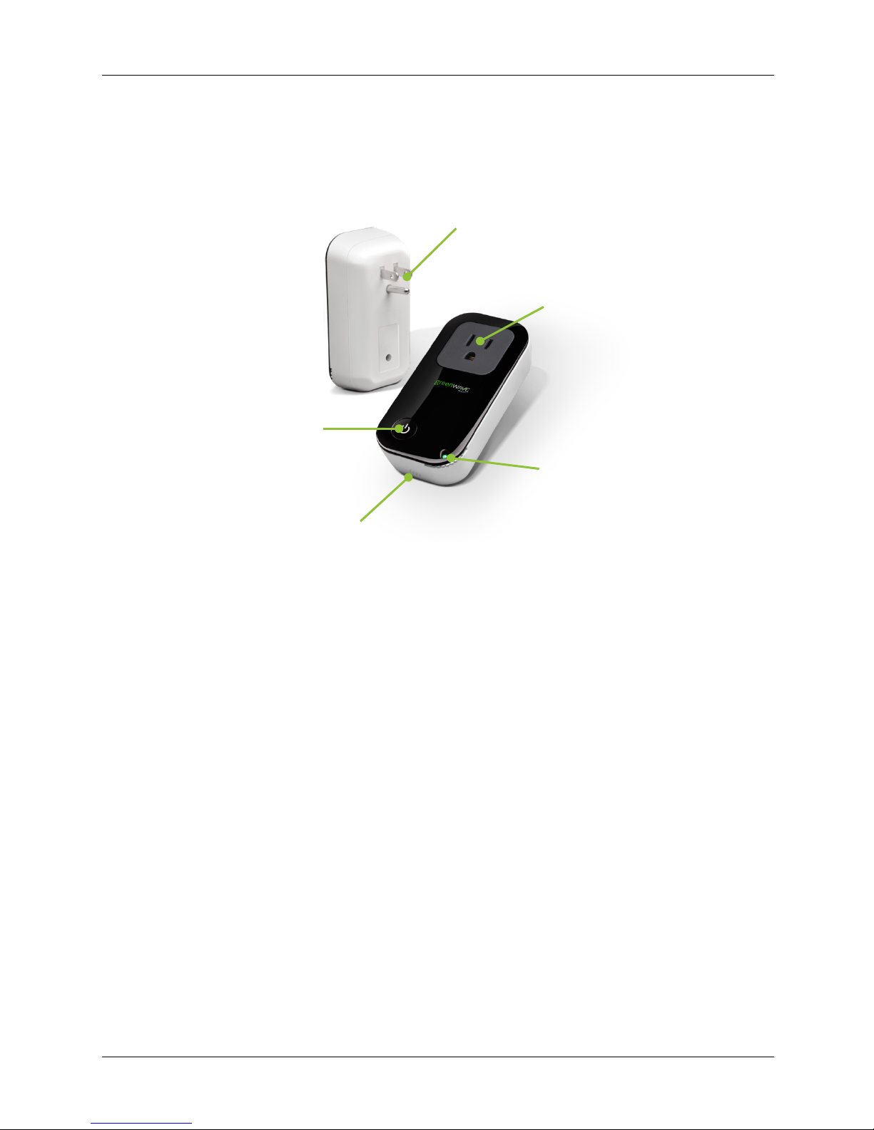
One-Port PowerNode
PowerNode Plug
Plugs into a standard electrical outlet.
PowerNode Port
Outlet where you plug your
device.
Room Color Selector
Specifies the room color
associated with the PowerNode.
Reset Button
Resets the PowerNode to factory
default settings.
Activity Indicator and Power Button
Displays the status of the connection to
the Gateway and controls the power. It
also synchronizes the PowerNode with
your Gateway.
Page 5
Introduction
PowerNodes User Guide | 3
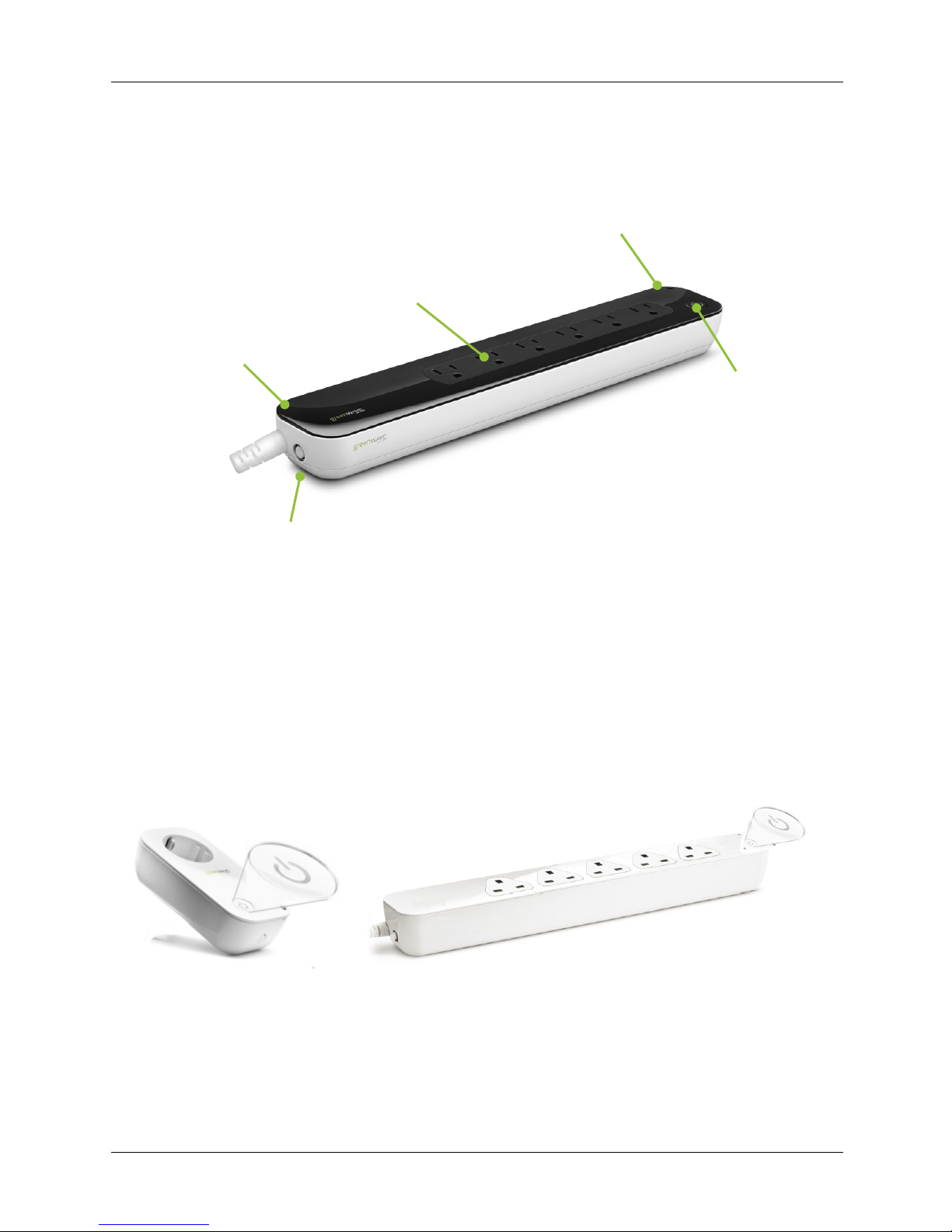
Multi-Port PowerNode
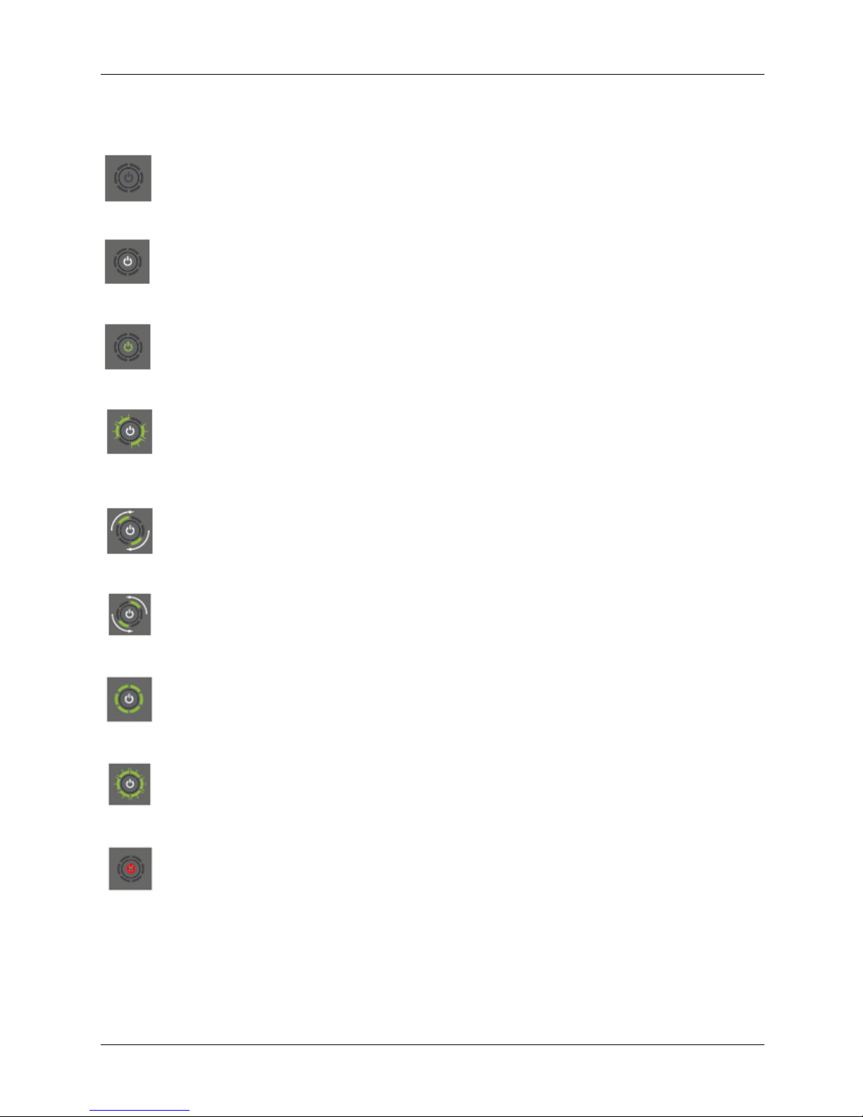
Indicators
The power button is combined with an indicator that displays patterns and colors to show its current
status.
PowerNode Ports
Outlets where you plug
your devices,
Room Color Selector
Specifies the room color
associated with the PowerNode.
Activity Indicator and Power
Button
Displays status of the connection
to the Gateway and controls the
power. It also synchronizes the
PowerNode with your Gateway.
PowerNode Power Cord
Plugs into a standard
electrical outlet.
Reset Button
Resets the PowerNode to
factory default settings.
Page 6
I ntroduction
PowerNodes User Guide | 4
The indicator may display the following patterns and colors:
Off (no color): All PowerNode ports are powered off.
Steady white in center: All PowerNode ports are powered on.
Steady green in center: Some ports on a multi-port PowerNode are powered on while
some are off. If you are expecting all ports to be powered on, access your online
account to verify your PowerNode and device settings and check their schedule.
Two flashing green bars on each side of white flashing center: The PowerNode
cannot communicate with the Gateway and may be out of range. You can move the
PowerNode closer to the Gateway or add additional PowerNodes closer to the Gateway.
The PowerNodes can piggyback on each other’s network connection.
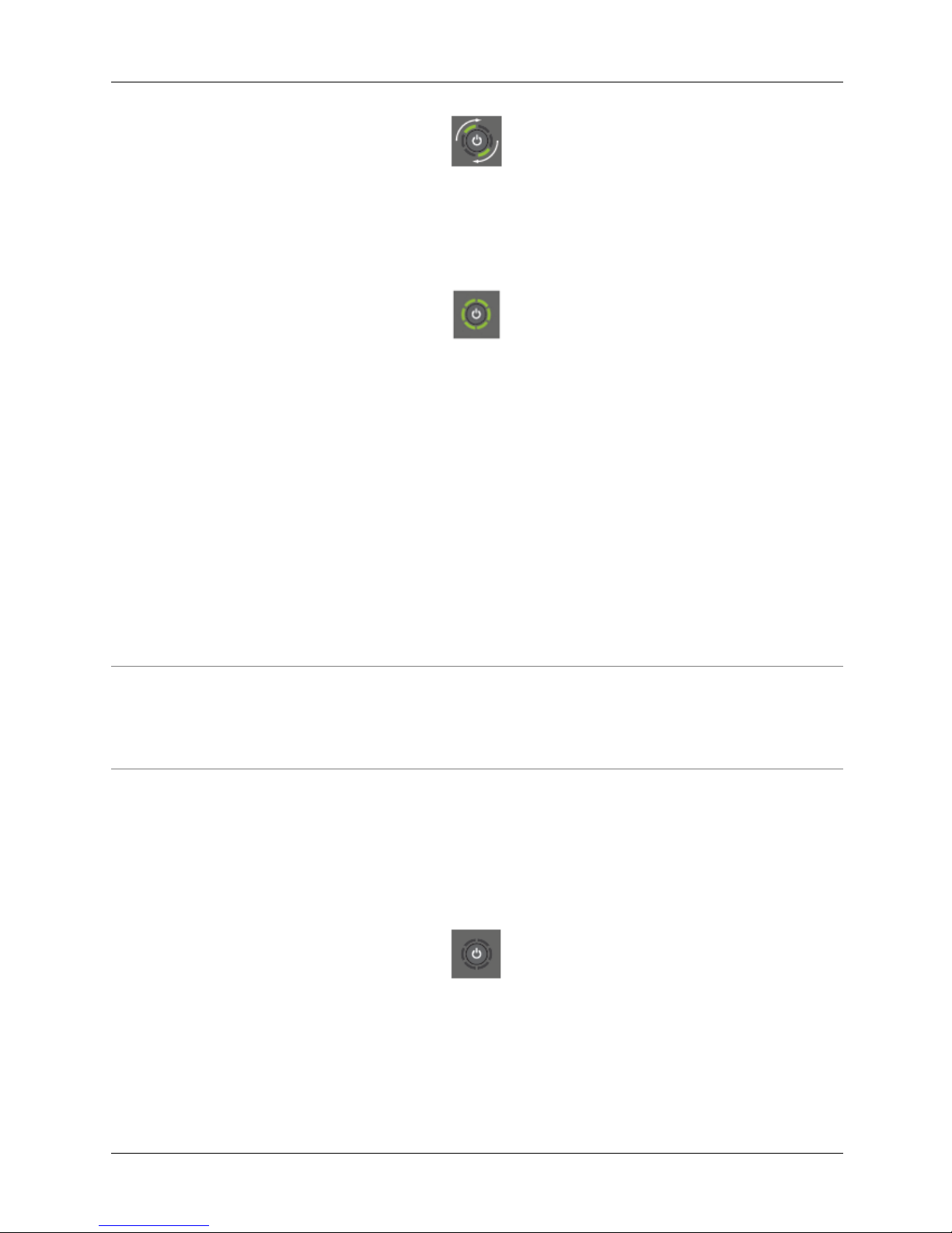
Two green bars rotating clockwise: The PowerNode is in inclusion mode to sync with
the Gateway.
Two green bars rotating counter-clockwise: The PowerNode is in exclusion mode to
disconnect from Gateway.
All steady green bars forming a circle: Inclusion or exclusion process was successful.
The bars remain green for several seconds.
All flashing green bars forming a circle: Inclusion or exclusion process was
unsuccessful.
Steady red in center: Over-current protection on the PowerNode is activated. Unplug
the attached device that caused the issue. Reset power by unplugging and replugging
the PowerNode into the electrical outlet.
Page 7

Getting Started
PowerNodes User Guide | 5
Getting Started
Before you plug in and install your PowerNodes, verify your Gateway is operating and connected to the
Internet. For information on setting up your Gateway, refer to the instructions that came with your
Gateway or energy management kit.
Follow these steps to install your PowerNode:
Step 1: Choose the devices and location
Step 2: Set the room color
Step 3: Sync the PowerNode with Gateway
Step 4: Add devices to the PowerNode
Step 5: Add connected devices to your online account
Step 1: Choose the Devices and Location
When choosing the devices and location to connect to your PowerNode, please keep the following in
mind:
• You should not plug devices, such as irons, space heaters and power tools into a PowerNode.
These types of devices should never be left unattended and should never be left in the on
position. Some devices, such as computers, are designed to require a staged power-down
process. It is possible that any instant loss of power, such as a PowerNode being powered off,
may cause temporary or permanent damage to such devices. We recommend you refer to the
manufacturer’s instructions before deciding if and how to use a PowerNode with such a device.!
• Medical equipment and other special appliances should never be powered on and off through a
PowerNode since you might inadvertently disconnect power to that device. You can connect the
device to your PowerNode, but be sure to use the white room color (the locked position). The
locked position stops the device from being powered remotely through the Web, mobile
application or Smart Controls.
• Attach only one device to each PowerNode port. Do not connect power strips and extension
cords or other PowerNodes to the PowerNode. Connecting more devices to one port interferes
with power consumption monitoring and may cause risk of malfunction and damage to your
PowerNode from overloading.
• To monitor and control your devices remotely, you must maintain a reliable wireless connection
between the PowerNode and Gateway. PowerNodes can piggyback on each other’s wireless
connection, allowing a distant PowerNode to connect through another PowerNode that is closer
to the Gateway.
Page 8
Getting Started
PowerNodes User Guide | 6
Perform the following steps:
1. Select the appliance or electronics devices to connect to your PowerNode.
2. Move the PowerNode to its chosen location and plug the PowerNode into a nearby electrical
outlet.
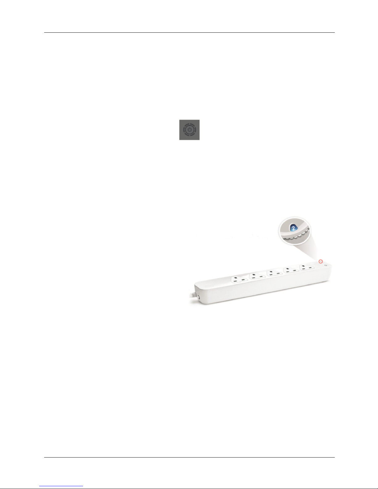
3. Turn the PowerNode off by pressing the Power button. The Power button turns dark to indicate
that power to the PowerNode ports is off.
Step 2: Set the Room Color
To easily identify rooms and devices powered by PowerNodes, your PowerNode has a corner wheel with
colored numbers. Rotate the wheel to select the colored number you want to represent the room or
device. This allows you to confidently turn devices on or off remotely using your online account as well as
set schedules that automatically turn your devices on or off at pre-defined times.
For example, you can set the room color to blue
(room number 2). When you access your online
account, the corresponding room is identified by
the same blue color as your PowerNode.
In addition, you can set PowerNodes in different
rooms to various colors, making those rooms
easy to identify when managing your power
sources.
If you use more than one PowerNode in the
same room you can set them to the same color.
Then, when you access your account, the same
colored PowerNodes will display together in the same room.
You can change the room color for a PowerNode as needed. For example, after having set a PowerNode
to a regular room color, you might later decide that you no longer want to be able to turn the device on
and off remotely. You could then switch the PowerNode’s room color to the unnumbered white locked
position to prevent control of the attached device remotely.
The PowerNode includes unnumbered white and black wheel colors that have the following purposes:
• White – allows you to monitor energy use for devices, but you cannot power those devices on or
off remotely. White is suggested for appliances, such as refrigerators or medical equipment that
should not be controlled remotely. The white selection locks all ports on a multi-port PowerNode.
• Black – allows you to manage devices without assigning them to a specific colored number. It
includes all devices under one generic grouping in your Web or mobile application. You can
change the room color at any time.
Page 9

Getting Started
PowerNodes User Guide | 7
You can change the room color for a PowerNode as needed. For example, you might decide that you no
longer want to be able to turn the connected device on and off remotely. You could then switch the
PowerNode’s room color to the white locked position to prevent control of the attached device remotely.
Perform the following:
• Turn the wheel to set the PowerNode to the colored number you want to use to identify the room
or device.
Step 3: Sync the PowerNode with Gateway
To allow the PowerNode and Gateway to communicate, you must sync your PowerNode with your
Gateway. This process is called “inclusion”.
Perform the following steps:
1. Temporarily, move the PowerNode close to the Gateway to ensure a strong radio signal.
If you will be syncing more than one PowerNode, start with the PowerNode that will be located
closest to the Gateway when the devices are plugged in. That way its wireless connection to the
Gateway will be available to more distant PowerNodes that may need to piggyback on the closer
PowerNode’s connection. You do not yet have to plug your devices into the PowerNode, so you
can leave the devices in their chosen location.
2. Plug the PowerNode into an electrical outlet that is located close to the Gateway. When the
PowerNode is powered, its activity indicator turns white.
3. On the Gateway, press and release the sync button once.
The activity indicator displays a clockwise rotating pattern. The Gateway is ready to be synced
with the PowerNode.
4. On the PowerNode, press and hold the sync button for approximately one second until the activity
indicator displays a clockwise rotating pattern. This indicates the PowerNode is attempting
inclusion.
Page 10
Getting Started
PowerNodes User Guide | 8
5. During this process, verify that the Gateway activity indicator still displays a clockwise rotating
pattern. If not, then the Gateway is not in inclusion mode and you must return to step 3.
After a few seconds, the rotating pattern on both the PowerNode and the Gateway stops. All bars
turn green forming a circle for several seconds. This indicates a successful inclusion.
If all bars on the activity indicator start flashing instead of forming a solid circle, then the
PowerNode inclusion process has failed, and you must start the sync process again. If syncing
continually fails even though the PowerNode is close to the Gateway, then it may be an indication
of a hardware fault, and the PowerNode might need replacing.
6. After you confirm the PowerNode is connected to the Gateway, move the PowerNode to the
location where you will plug in your devices. When you unplug the PowerNode to move it, the
PowerNode remains synced to the Gateway.
Step 4: Add Devices to the PowerNode
You can add your devices to the PowerNode, then add the devices to your online account. If you are
installing more than one PowerNode, you can wait until all PowerNodes are installed to add the devices
to your online account at the same time.
Note: PowerNodes and Gateway that are components of an energy management kit are synced prior to shipping.
If the PowerNodes is not a component of an energy management kit, then you must first sync it with your Gateway.
For additional information, refer to Sync the PowerNode with Gateway if Not Part of a Kit section in the Advanced
Z-Wave Tasks chapter.
Perform the following steps:
1. Turn the device off, unplug it from any power source, and then plug it into the PowerNode port.
2. Turn the PowerNode on by pressing the power button. The power button illuminates white to
indicate the power is on.
3. Turn the devices on. They are now part of your energy management system.
Step 5: Add Connected Devices to Your Online Account
You must set up your devices in your online account to be able to control and monitor them remotely.
Page 11

Getting Started
PowerNodes User Guide | 9
Perform the following steps:
1. Using your Web browser or smart device, log in to your account.
When you log in to your account, you can also access online help for additional information and
instructions on working with the Web application.
2. Click the My Settings menu.
3. When the Settings page opens, click the Set Up Wizard option in the menu on the left side of
the page.
4. Click the Rooms and PowerNodes option under Set Up Wizard.
5. Click the Launch Setup Wizard button. The wizard opens and walks you through the setup
process.
Page 12

Managing PowerNodes
PowerNodes User Guide | 10
Managing PowerNodes
You can perform the following tasks:
• Add or change devices connected to the PowerNode
• Move the PowerNode to a different room or change the wheel color
• Re-establish the Gateway’s radio signal after moving a PowerNode
Add or Change Devices Connected to PowerNode
To connect a new device to your PowerNode at a later time, you can simply plug the device into your
PowerNode. If you are replacing a device that was previously plugged into the PowerNode, the data from
the old device will remain in your account as historical information. All new data will be based on your
new device.
After plugging the new device into the PowerNode, you must update your online account by using the
following instructions:
1. Using your Web browser, log in to your account.
2. Click the My Home menu.
3. On the carousel, select the room card and then click the room icon for the room containing
the PowerNode.
4. Click the icon for the port where you plugged in the new device. If you are replacing an old
device, the icon for the old device will still display.
5. Under the Basic tab at the bottom of the page, click the Type field that says Identify me.
If you are replacing an old device, the old device type displays next to the label.
The wizard opens and walks you through updating the device information.
Move PowerNode to a Different Room or Change the Wheel Color
If necessary, you can move your PowerNode to a different room and/or change its wheel color. The only
requirement is that the PowerNode be able to maintain its wireless network connection with the Gateway
Common tasks include:
• Change the wheel color, while keeping the current devices connected. For example, after having
set a PowerNode to a regular room color, you might decide later that you no longer want to be
able to turn the device on and off remotely. You could then switch the PowerNode’s room color to
Page 13

Managing PowerNodes
PowerNodes User Guide | 11
the white locked position. When you change the wheel color, the change is automatically
transmitted to your online account so that you see the correct room color when accessed through
a Web browser or smart device.
• Change the wheel color and connected devices. The wheel color change is automatically
transmitted to your online account. However, if you are replacing devices on your PowerNode,
you must update the device information in your online account.
• Move the PowerNode to a new location, but keep the same room color and devices. For example,
you may need to move the PowerNode to improve reception. When you move a PowerNode you
must have the Gateway re-establish its radio signals with the PowerNodes on your energy
management system.
Re-establish the Gateway’s Radio Signal
When you move a PowerNode or manually sync a PowerNode with a Gateway, you must have the
Gateway re-establish its radio signal with the PowerNodes on your energy management system.
You can perform this through your online account by using the following steps:
1. Log in to your online account using a Web browser or smart device.
2. Click the My Settings menu.
3. When the Settings page opens, click the Set Up Wizard option in the menu on the left side of
the page.
4. Click the Rooms and PowerNodes option under Set Up Wizard.
5. Click the Repair Network button. A command is automatically sent to your Gateway to establish
the best radio connection with your PowerNodes.
Page 14

Advanced Z- Wave Tasks
PowerNodes User Guide | 12
Advanced Z-Wave Tasks
This chapter is for Advanced Users only.
The PowerNodes communicate wirelessly with the Gateway by use of Z-Wave mesh networking, which is
a robust connection technology designed for home automation with security and privacy. The more ZWave compatible devices installed in your home, the better coverage your energy management system
will have. As a Z-Wave enabled device, the PowerNode is compatible with Z-Wave enabled networks and
hardware from other manufacturers.
Remove PowerNode from Network
A PowerNode that has been previously used with a different Z-Wave network must have its association
(homeID) with the other network removed before you can connect it to your energy management system.
This process is called “exclusion” and requires you to perform steps with both the Gateway and the
PowerNode.
To complete the exclusion process, verify that your Gateway is plugged in and working, and then perform
the following steps:
1. Move the PowerNode close to the Gateway to ensure a strong radio signal.
2. Plug the PowerNode into an electrical outlet. When the PowerNode is powered, its activity
indicator turns white.
3. On the Gateway, press and hold the Sync button until the activity indicator begins to display a
counter-clockwise rotating pattern.
The Gateway is ready to perform the exclusion of the PowerNode.
4. On the PowerNode, press and hold the Sync button for approximately one second until the
PowerNode activity indicator begins to display a counter-clockwise rotating pattern. The
PowerNode is attempting exclusion.
Page 15

Advanced Z- Wave Tasks
PowerNodes User Guide | 13
5. During this process, verify that the Gateway activity indicator still displays a counter-clockwise
rotating pattern. If not, then the Gateway is not in exclusion mode and you must repeat step 3.
After a few seconds, the rotating pattern on both the PowerNode and the Gateway stops and all
bars turn green forming a circle for several seconds. This indicates a successful exclusion.
If all bars on the activity indicator start flashing instead of forming a solid circle, then the
PowerNode exclusion process has failed, and you must start the process again.
Page 16

Operating Information
PowerNodes User Guide | 14
Operating Information
Keep Radio Signals Clear
Your Gateway and wireless devices have antennas built-in for radio communication with Internet services
and your energy management system. Just as you might experience reception problems on your mobile
phone inside a building, your Gateway can have trouble communicating with wireless devices if their radio
signals are blocked by obstacles, such as large metal panels or walls containing wire mesh.
Several factors could affect radio signal strength between the Gateway and wireless devices:
• If the Gateway is too close to a wireless router, the radio signals from the router could interfere
with the signals the Gateway is processing from the wireless devices. However, the wireless
devices themselves do not typically have problems when used close to wireless routers.
• If the Gateway is very close to the floor, its signal could bounce off the floor and possibly cause
interference with the radio signals.
• If the Gateway is positioned vertically, such as attached to the wall, the radio signal strength
could be reduced.
• If the Gateway is behind a metal object, the radio signals could be blocked.
• If a wireless device is placed a significant distance or through several walls from the Gateway or
other smart device connected through the mesh network, the radio signals could lose strength.
• If the non-visible construction of a wall contains such things as large metal panels or wire mesh,
the walls could block the radio signal between the Gateway and devices. This may apply to an
entire wall or only specific areas of a wall.
Indoor Use Only
Your PowerNode should be used only in dry, indoor locations. Do not use your PowerNode in highhumidity locations such as greenhouses, saunas, washrooms or patios. Do not use your PowerNode in
locations where it can get wet, such as near aquariums or running water.
Do Not Disassemble
Your PowerNode has no user-serviceable parts inside. If you experience persistent malfunctions, please
contact Customer Service to arrange for repair at a certified service location. Do not attempt to
disassemble the PowerNode for any reason.
Page 17

Operating Information
PowerNodes User Guide | 15
Disposing of Your Used Product
This product complies with the WEEE Directive (2002/96/EC) marking
requirements. The affixed label indicates that you must not discard this
electrical / electronic product in domestic household waste.
WEEE Product Category. With reference to the equipment types in the WEEE
Directive Annex 1, this product is classed as category 3 “IT and
Telecommunications Equipment.”
DO NOT DISPOSE IN DOMESTIC HOUSEHOLD WASTE. To return unwanted products, contact your
local GreenWave Reality office.
Page 18

Safety Information
PowerNodes User Guide | 16
Safety Information
Caution
This device features an internal protection that will disconnect the surge protective component at the end
of its useful life but will maintain power to the load—now unprotected. If this situation is undesirable for
the application, follow the manufacturer’s instructions for replacing the device.
Risk of Electric Shock. Do not plug into another relocatable power tap.
Dangerous Devices
You should strongly consider whether to plug certain devices into PowerNodes:
• Hazardous if left unattended: Certain devices such as irons, space heaters and power tools
should never be left unattended and should never be left in the on position unless you are actively
using the device.
• Hazardous if power is interrupted: Certain devices such as medical equipment should never be
powered on and off through a PowerNode. Other devices such as refrigerators should also never
be powered on and off through a PowerNode since you might inadvertently disconnect power to
that device. Such devices should only be plugged into a PowerNode if the color wheel is in the
locked position.
If you want to plug any of these devices into a PowerNode to measure energy use information, then you
should set the color wheel on the PowerNode to the locked position (white wheel color). This will require
you to power the devices on and off directly on the device itself.
Page 19

About GreenWave Reality
PowerNodes User Guide | 17
About GreenWave Reality
GreenWave Reality is an Internet of Things (IoT) software and services company whose 360º solution
enables leading brands to quickly and easily deliver new products and services to consumers.
GreenWave works closely with its customers to design, build, deploy and manage connected appliances
and services that both improve efficiency and enhance productivity. Learn more about GreenWave at
www.GreenWaveReality.com or follow us on Twitter at @GrnWaveReality.
North America
133 Technology, Suite 200, Irvine CA-92618, USA
Tel. +1 714 805 WAVE (9283)
na@greenwavereality.com
Asia-Pacific
10 Science Park Road, #02-07/08 The Alpha, Science Park 2, Singapore 117684
Tel. +65 3157 1700
apac@greenwavereality.com
Europe
GreenWave Reality ApS.
Bregneroedvej 96
3460 Birkerød
DENMARK
Tel. +45 6913 2333
eu@greenwavereality.com
Page 20

Product Specifications
PowerNodes User Guide | 18
Product Specifications
General Specifications
!
Features
1, 5, or 6 sockets
Overcurrent protection
Surge protection (UK & NA models only)
Radio Frequency
Z-Wave Radio Frequency
868.4MHz (EU), 921.4MHz (AS/NZ), 908.4MHz (NA)
Z-Wave Maximum InterNode Range
30m; Line of sight
DeviceDNA
v1.0
Power – For power levels in specific regions, refer to the Specifications by Region section
Power (Rated)
120V ~ 240V 50/60Hz
Maximum Load Current
15A
Standby Power
<1W
Load Monitoring Precision
±0.1W
Environmental
Operating Temperature
0°C ~ +40°C
Operating Humidity
Up to 90% RH
Storage Temperature
-20°C to +60°C
IP Class – Moisture
Tolerance
IP20
Certificates
Z-Wave Certified
Supported Command Class
Meter CC V2
Multichannel CC V2 for multi-port only
Association CC V1
Configuration CC V1
Indicator CC V1
CRC-16 Encapsulation CC V1
Page 21

Product Specifications
PowerNodes User Guide | 19
Specifications by Region
!
Regions
AUS/NZ
EU
SK/GS
UK
NA
!
Model
1 port - NS24x-I
1 port - NS21x-U
1 port - NS31x-F
1 port - NS21x-G
1 port - NS22x-B
x=0; White
x=2; Black
6 port - NP24x-I
6 port - NP21x-KF
6 port - NP31x-F
5 port - NP21x-G
6 port - NP22x-B
Socket Type
Type I
Type C and K
Type F
Type G
Type B
Plug Type
AS/NZS 3112
CEE 7/17 and
CEE7/7
DIN49441
BS1363-1
NEMA 5-15P
Voltage (AC)
240V ~50Hz
250V~50/60Hz
250V~50Hz
250V~50Hz
120V ~60Hz
Amps
10A
10A
10A
13A
15A
Certificates
C-Tick, SAA
CE CE, GS
CE
FCC, UL
Protection
Over-current
Over-current
Over-current
Over-current
Surge
Over-current
Surge
Version: 8_2014_03_27
Page 22

Product Specifications
PowerNodes User Guide | 20
Federal Communication Commission Interference Statement
This device complies with Part 15 of the FCC Rules. Operation is subject to the following two conditions: (1) This device may not
cause harmful interference, and (2) this device must accept any interference received, including interference that may cause
undesired operation.
This equipment has been tested and found to comply with the limits for a Class B digital device, pursuant to Part 15 of the FCC
Rules. These limits are designed to provide reasonable protection against harmful interference in a residential installation. This
equipment generates, uses and can radiate radio frequency energy and, if not installed and used in accordance with the
instructions, may cause harmful interference to radio communications. However, there is no guarantee that interference will not
occur in a particular installation. If this equipment does cause harmful interference to radio or television reception, which can be
determined by turning the equipment off and on, the user is encouraged to try to correct the interference by one of the following
measures:
• Reorient or relocate the receiving antenna.
• Increase the separation between the equipment and receiver.
• Connect the equipment into an outlet on a circuit different from that to which the receiver is connected.
• Consult the dealer or an experienced radio/TV technician for help.
FCC Caution: Any changes or modifications not expressly approved by the party responsible for compliance could void the user's
authority to operate this equipment.
IMPORTANT NOTE:
FCC Radiation Exposure Statement:
This equipment complies with FCC radiation exposure limits set forth for an uncontrolled environment. This equipment should be
installed and operated with a minimum distance of 20cm between the radiator and your body.
Declaration(s) of Conformity
These CE Marked GreenWave Reality products incorporating Radio and Telecoms Terminal Equipment
functionality are in compliance with the essential requirements and other relevant provisions of Directive
1999/5/EC.
A copy of the original CE Declaration of Conformity is on file and available upon request for all CE
Marked GreenWave Reality products. Please visit www.greenwavereality.com to obtain a copy of the
Declaration.
The use of such device might not be harmonized throughout EU and EFTA Member States. The Final
Integrator of the product shall check that the use of such devices for power node is allowed for placing on
the market in any particular Member State.
 Loading...