


GREENTEL M2M Industrial Cellular Router
User Manual
For R200 M2M Industrial Cellular Router
- 1 -

ANNOUNCEMENTS ............................................................................................................................. 5
1. ROUTER INTRODUCTION ............................................................................................................. 9
1.1 FEATURES: ....................................................................................................................................... 9
1.2 APPLICATIONS: .............................................................................................................................. 10
1.3 PRODUCT KIT: ............................................................................................................................... 10
2. HARDWARE INTRODUCTION .................................................................................................... 11
2.1 R2X1HHW AND R2X1GC55 ......................................................................................................... 11
2.2 INTERFACE (FROM UP TO DOWN) .................................................................................................... 11
2.3 LED INDICATOR ............................................................................................................................ 12
2.4 R2X1UU ....................................................................................................................................... 13
2.5 R2X4HHW AND R2X4GC55 ......................................................................................................... 14
2.6 R2X4UU ....................................................................................................................................... 15
2.7 INSERT SIM/UIM .......................................................................................................................... 16
2.8. SCREW PLUGGABLE TERMINAL BLOCK ......................................................................................... 16
2.9 MAINTENANCE NOTES .................................................................................................................. 17
3. APPLICATION INTRODUCTION ................................................................................................. 18
4. ACCESSING THE ROUTER ......................................................................................................... 19
4.1 PC CONFIGURATION ...................................................................................................................... 19
4.2 LOGIN............................................................................................................................................ 19
4.3 SYSTEM CONFIGURATION .............................................................................................................. 20
4.3.1 SYSTEM -> BASIC SETUP ............................................................................................................ 20
4.3.2 SYSTEM -> TIME ......................................................................................................................... 21
4.3.3 SYSTEM -> SERIAL PORT ............................................................................................................. 21
4.3.4 SYSTEM -> ADMIN ACCESS ......................................................................................................... 22
4.3.5 SYSTEM -> SYSTEM LOG............................................................................................................. 24
4.3.6 SYSTEM -> CONFIG MANAGEMENT ............................................................................................. 25
4.3.7 SYSTEM -> UPGRADE ................................................................................................................. 25
4.3.8 SYSTEM -> REBOOT .................................................................................................................... 27
4.3.9 SYSTEM -> LOGOUT ................................................................................................................... 28
4.4 NETWORK ..................................................................................................................................... 28
4.4.1 NETWORK -> DIALUP ................................................................................................................. 29
4.4.2 NETWORK -> LAN ..................................................................................................................... 31
4.4.3 DNS ........................................................................................................................................... 32
4.4.4 DDNS ........................................................................................................................................ 32
4.4.5 STAT IC ROUTE ............................................................................................................................ 33
4.4.6 WAN (R2X4 ONLY) .................................................................................................................... 34
4.4.7 DMZ PORT (R2X4 ONLY) ........................................................................................................... 37
- 2 -

4.4.8 PORT MODE (R2X4 ONLY) .......................................................................................................... 37
4.5 SERVICE ........................................................................................................................................ 38
4.5.1 SERVICES -> DHCP SERVICE ...................................................................................................... 38
4.5.2 SERVICES -> DNS RELAY ........................................................................................................... 39
4.5.3 SERVICES -> VRRP .................................................................................................................... 40
4.5.4 SERVICES -> DEVICE MANAGER ................................................................................................. 40
4.5.5 SERVICES -> DTU ...................................................................................................................... 41
4.6 FIREWALL ...................................................................................................................................... 42
4.6.1 FIREWALL -> BASIC .................................................................................................................... 42
4.6.2 FIREWALL -> FILTERING ............................................................................................................. 43
4.6.3 FIREWALL -> PORT MAPPING ...................................................................................................... 44
4.6.4 FIREWALL -> VIRTUAL IP MAPPING ............................................................................................ 44
4.6.5 FIREWALL -> DMZ ..................................................................................................................... 45
4.6.6 FIREWALL -> MAC-IPBUNDLING .............................................................................................. 45
4.7 QOS .............................................................................................................................................. 46
4.8 VPN .............................................................................................................................................. 46
4.8.1 VPN -> IPSEC BASIC SETTING .................................................................................................. 47
4.8.2 VPN -> IPSEC TUNNELS ........................................................................................................... 48
4.8.3 VPN -> GRE TUNNELS .............................................................................................................. 51
4.8.4 VPN -> L2TP CLIENTS ............................................................................................................... 51
4.8.6 VPN -> L2TP SERVER ................................................................................................................ 52
4.8.7 VPN -> PPTP CLIENTS ............................................................................................................... 52
4.8.8 VPN -> PPTP SERVER ................................................................................................................ 53
4.8.9 VPN -> OPENVPN TUNNELS ..................................................................................................... 54
4.8.10 VPN -> OPENVPN ADVANCED................................................................................................. 55
4.8.10 VPN -> CERTIFICATE MANAGEMENT ....................................................................................... 55
4.9 TOOLS ........................................................................................................................................... 56
4.9.1 TOOLS -> PING .......................................................................................................................... 56
4.9.2 TOOLS -> TRACEROUTE .............................................................................................................. 56
4.9.3 TOOLS -> LINK SPEED TEST ....................................................................................................... 57
4.10 STATU S ........................................................................................................................................ 57
4.10.1 STAT US -> SYSTEM ................................................................................................................... 58
4.10.2 STAT US -> MODEM ................................................................................................................... 58
4.10.3 STAT US -> NETWORK CONNECTIONS ........................................................................................ 59
4.10.4 STAT US -> ROUTE TABLE .......................................................................................................... 59
4.10.5 STAT US -> DEVICE LIST ............................................................................................................ 59
4.10.6 STAT US -> LOG ......................................................................................................................... 60
5. HOW TO UPGRADE NEW FIRMWARE ..................................................................................... 61
6. HOW TO DIAGNOSE ..................................................................................................................... 62
7. CONFIGURE VIA TELNET ........................................................................................................... 63
- 3 -

8. CONFIGURE VIA SERIAL PORT ................................................................................................ 64
9. HOW TO RESET TO FACTORY DEFAULTS SETTINGS ........................................................ 68
9.1 RESET BY SOFTWARE ..................................................................................................................... 68
9.2 RESET BY HARDWARE ................................................................................................................... 68
9.3 RESET BY TELNET ......................................................................................................................... 69
10. SUPPORT ...................................................................................................................................... 71
- 4 -

Announcements
Thank you for choosing our product. GREENTEL R200 series is Machine-to-machine (M2M)
industrial cellular router with Din-rail mounting, which works on 2G/3G cellular networks,
provides reliable and robust wireless connections.
GREENTEL R200 series is specified for industrial M2M usage. Designed to endure extreme
conditions, such as temperatures ranging from -25°C to +70°C and low power consumption.
GREENTEL R200 series also supports the OpenVPN, PPTP, L2TP, GPE, IPSec VPN tunnel
providing high-grade network security.
Please read this manual carefully before using the product.
Copyright Announcement
Copyright GREENTEL LIMITED 2010.
All rights reserved.
Reproduction, transfer, distribution or storage of part or all of the contents in this document in
any form without the prior written permission of GREENTEL is prohibited.
Information Edition: GL – A – R200 – 2.5
- 5 -

Important Safety Information
This product is not intended for use in the following
circumstances
x Area(s) where radio transmission equipment (such as cell phone) are not permitted.
x Hospitals, health care facilities and area(s) where cell phones are restricted by law.
x Gas stations, fuel storage and places where chemical are stored.
x Chemical plants or places with potential explosion hazard.
x Any metal surface that may weaken the radio signal level.
x The appliance is intended to be installed in restricted access location. Only service
person or authorized person is allowed to access.
RF safety distance
For GPRS router, the compliance boundary distance is r=0.26m for GSM 900MHz and r=0.13m
for DCS 1800 MHz.
For HSUPA router, the compliance boundary distance is r=0.26m for GSM 900MHz and
r=0.13m for DCS 1800 MHz, r=.0.094 for WCDMA 900MHz, r=0.063 for WCDMA 2100MHz.
Warning
This is a class A product. In a domestic environment this product may cause radio interference
in which case the user may be required to take adequate measures.
- 6 -

Agency approvals and standards compliance
For R211HHW-232 and R201HHW-232
Type Approval / Compliance
3.1a Health EN 50385: 2002
3.1a Safety EN 60950-1:2006+A11
3.1b EMC EN 301 489-1 V1.8.1
EN 301 489-7 V1.3.1
EN 301 489-24 V1.4.1
EN 300 386 V1.4.1
3.2 Radio EN 301 511 V9.0.2
EN 301 908-1 V3.2.1
EN 301 908-2 V3.2.1
For R211GC55-232 and R201GC55-232
Type Approval / Compliance
3.1a Health EN 50385: 2002
3.1a Safety EN 60950-1:2006+A11
3.1b EMC EN 301 489-1 V1.8.1
EN 301 489-7 V1.3.1
EN 300 386 V1.4.1
3.2 Radio EN 301 511 V9.0.2
- 7 -

WEEE Notice
The Directive on Waste Electrical and Electronic Equipment (WEEE), which entered into force
as European law on 13th February 2003, resulted in a major change in the treatment of
electrical equipment at end-of-life.
The purpose of this Directive is, as a first priority, the prevention of WEEE, and in addition, to
promote the reuse, recycling and other forms of recovery of such wastes so as to reduce
disposal.
The WEEE logo (shown at the left) on the product or on its box indicates that this product must
not be disposed of or dumped with your other household waste. You are liable to dispose of all
your electronic or electrical waste equipment by relocating over to the specified collection point
for recycling of such hazardous waste. Isolated collection and proper recovery of your
electronic and electrical waste equipment at the time of disposal will allow us to help conserving
natural resources. Moreover, proper recycling of the electronic and electrical waste equipment
will ensure safety of human health and environment. For more information about electronic and
electrical waste equipment disposal, recovery, and collection points, please contact your local
city centre, household waste disposal service, shop from where you purchased the equipment,
or manufacturer of the equipment.
- 8 -

1. Router Introduction
GREENTEL R200 series is Machine-to-machine (M2M) industrial cellular router with
Din-rail mounting, which works on 2G/3G cellular networks, provides reliable and robust
wireless connections.
GREENTEL R200 series is specified for industrial M2M usage. Designed to endure
extreme conditions, such as temperatures ranging from -25°C to +70°C and low power
consumption.
GREENTEL R200 series also supports the OpenVPN, PPTP, L2TP, GPE, IPSec VPN
tunnel providing high-grade network security.
1.1 Features:
Highly Reliable Network Performance
z High performance platform, 200 MIPS ARM9, 8 Mbytes NORFlash, 16 Mbytes
SDRAM
z Software and hardware watchdog
z Always online: PPP LCP echo and ICMP keep alive for link inspection
z Dial on demand activated by Call/SMS/Local data flow
z High sensitivity: low signal strength required (CSQ>12)
z Remote and local firmware upgrade based on redundant firmware backup
z Large scale remote management via Greentel Device Manager
Ease to Use
z Embedded Linux system, TCP/IP and PPP stack, Plug and Play
z Configuration via WEB, TELNET, Hyper Terminal and SSH
z Backup and restore settings
z Reset button, software and hardware reset to factory default settings
z LED indicators for three level cellular network signal strength
z LED indicators for Power, Status, Warn, Error, Modem
Security
z VPN IPSec: DES, 3DES, AES, MD5 and SHA-1
z Authentication: Pre-shared key, digital certificate
z Support OpenVPN, PPTP, L2TP, GRE tunnels
z Firewall: Stateful Packet Inspection(SPI), filtering multicast, filtering PING packet,
preventing DoS attack, different firewall strategies
z Access control: Access control of TCP, UDP, ICMP packet
z MAC and IP filter, MAC address bundling
z DMZ: support virtual servers
z VRRP: Hot backup, auto switch to slave router when master router failed
- 9 -

Robust design for Industrial Application
z Rugged casing with DIN-rail mounting and wall mounting
z Inside SIM card slot, provides SIM card anti-steal
z Industrial power terminal block, 12 to 48VDC wide range voltage power supply,
anti-RCE (reverse connection error), over-current protection
z One Ethernet port (R2x1xx series) or four Ethernet port (R2x4xx series), one RS232
for debug console, one serial port for data transmission (RS232 or RS485 optional)
z Support DTU mode, data transparent transmission via serial port
z Support Modbus RTU to Modbus TCP via serial port
z Wide range operation temperature: -25°C to 70°C
z Operation humidity: 5% to 95%, non-condensing
z IP30 grade protection
z Optimized EMC design
1.2 Applications:
z Machine-to-machine (M2M)
z Tel em e t r y
z SCADA
z Monitoring and Surveillance
z DSL/Cable Infrastructure Backup
z AVL
z Credit card verifications, POS and ATM
1.3 Product Kit:
z M2M Industrial Cellular Router
z AC/DC Adapter
z Rubber antenna and magnetic mount antenna optional
z DIN-rail optional
z RS232 to RS485 converter optional
z Ethernet Cable RJ45
z Debug console cable RJ45-RS232 optional
z CD
- 10 -
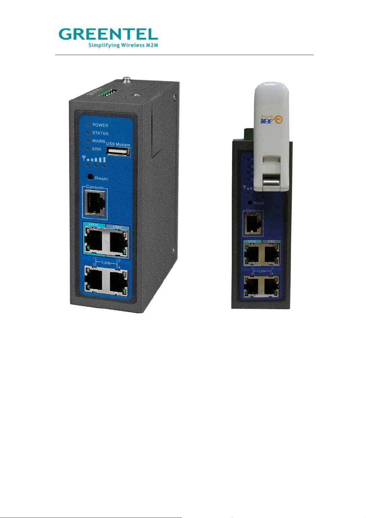
2. Hardware Introduction
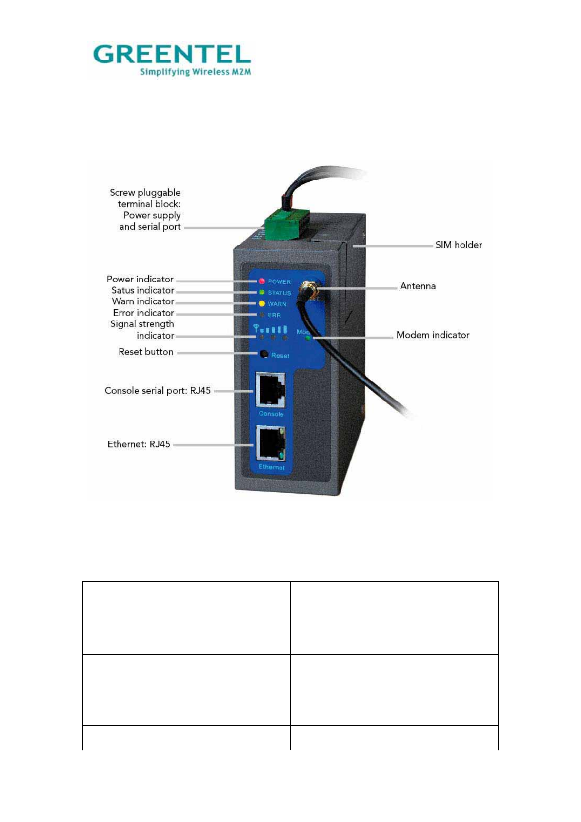
2.1 R2x1HHW and R2x1GC55
Figure 2.1 Front Panel
2.2 Interface (from up to down)
Name Description
Screw pluggable terminal block Including power supply connector and serial
port interface (one RS232 or one RS485
optional)
SIM holder Insert the SIM into socket
Antenna Cellular antenna
Reset button Power off router, press and hold ‘reset
button’, power on at the same time (please
do not release the reset button), when ERR
LED starts blinking, please release the reset
button, after few seconds, it will reset to
factory defaults.
Console port Debug console serial port
Ethernet port LAN
- 11 -
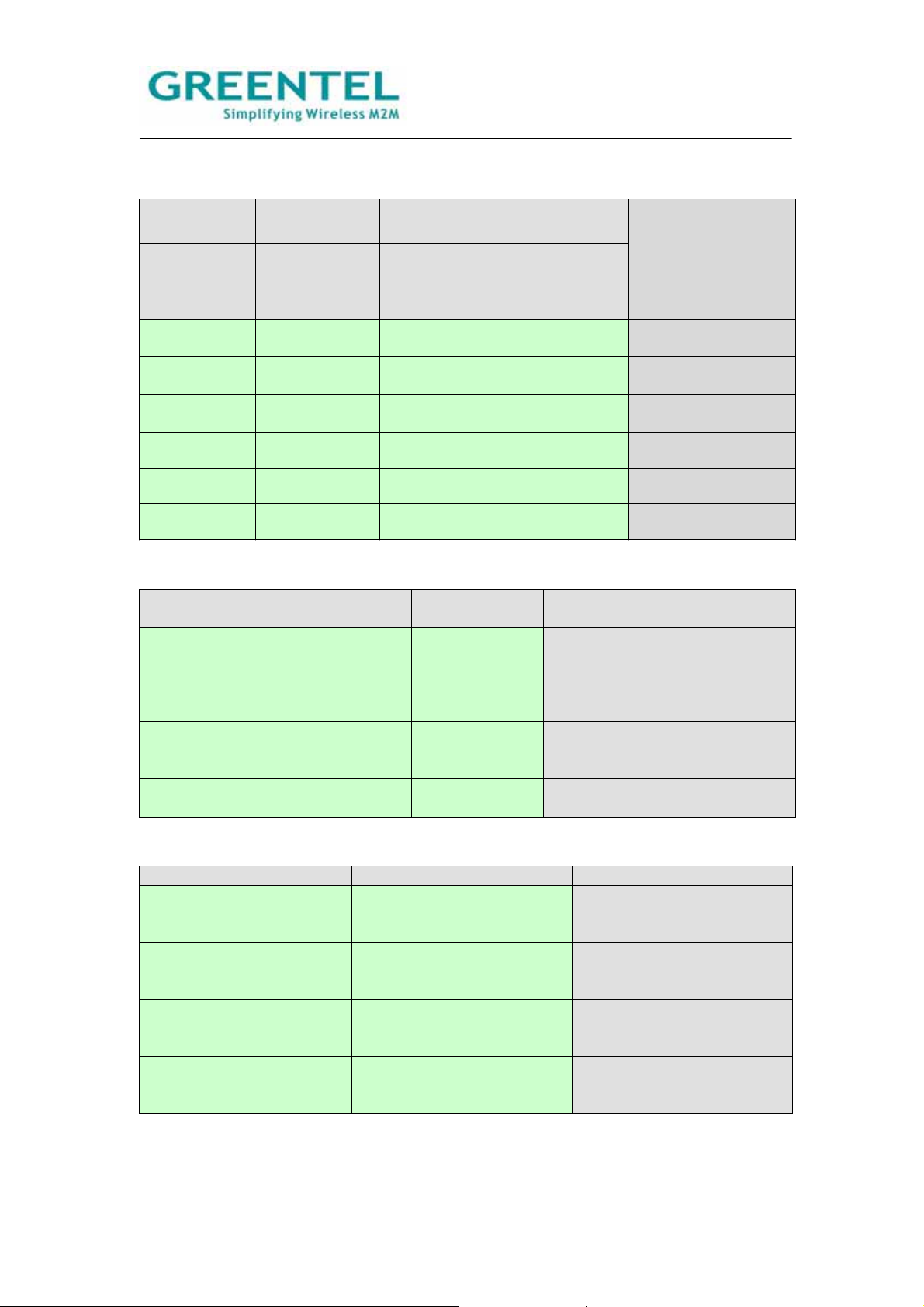
2.3 LED indicator
System indicators
POWER STATUS WARN ERROR
Power supply
indicator
(Red)
Running
status
indicator
Alarm
indicator
(Yellow)
Error indicator
(Red)
Description
(Green)
On On On Off Powered on
On Blinking On Off Power-on is
successful
On Blinking Blinking Off Dialing to cellular
networks
On Blinking Off Off Dialing successful
On Blinking Blinking Blinking Upgrading firmware
On Blinking On Blinking Reset is successful
Signal Strength indicators
Signal strength
indicator 1
Signal strength
indicator 2
Signal strength
indicator 3
Description
On Off Off Signal Status 1-9: signal status is
poor, please check if the antenna
is correctly installed, and the
router is located under good
signal coverage.
On On Off Signal Status 10-19: signal
status is average and the
equipment can work normally.
On On On Signal Status 20-31: signal
status is good.
Ethernet Interface indicators
Yellow indicator Green indicator Description
On On A normal 100M connection
is through this port, no data
packets are transmitting.
Blinking On A normal 100M connection
is through this port, data
packets are transmitting.
On Off A normal 10M connection is
through this port, no data
packets are transmitting.
Blinking Off A normal 10M connection is
through this port, data
packets are transmitting.
- 12 -
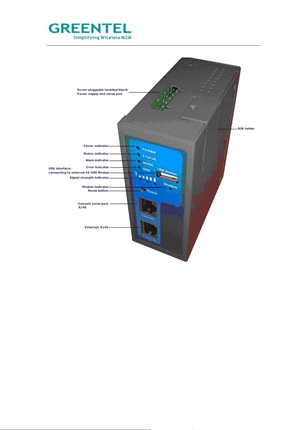
2.4 R2x1UU
Figure 2.2 Front Panel (USB host type – without built in cellular module)
- 13 -
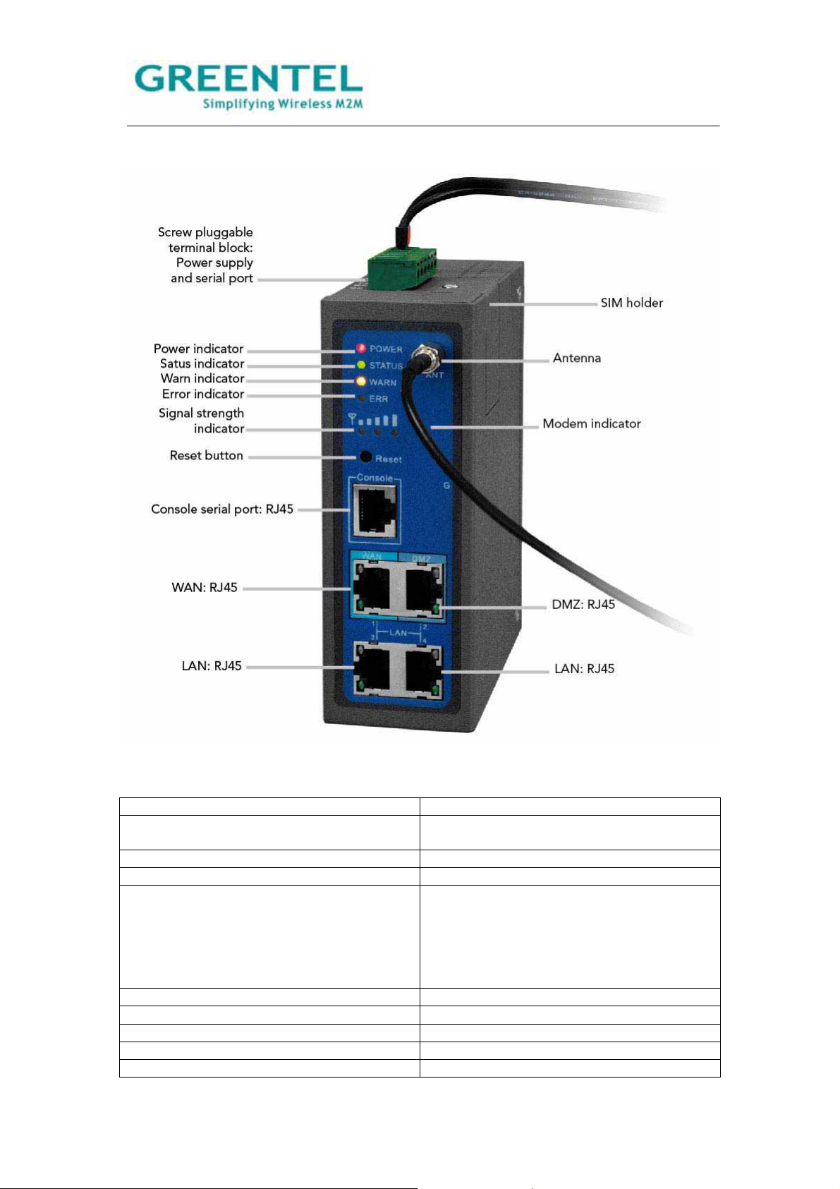
2.5 R2x4HHW and R2x4GC55
Figure 2.3 Front Panel
Name Description
Screw pluggable terminal block Including power supply connector and serial
port interface (RS232 and RS485 optional)
SIM holder Insert the SIM into socket
Antenna Cellular antenna
Reset button Power off router, press and hold ‘reset
button’, power on at the same time (please
do not release the reset button), when ERR
LED starts blinking, please release the reset
button, after few seconds, it will reset to
factory defaults.
Console port Debug console serial port
Ethernet port WAN
Ethernet port DMZ
Ethernet port LAN
Ethernet port LAN
- 14 -
2.6 R2x4UU
- 15 -

2.7 Insert SIM/UIM
Figure 2.4: Insert SIM/UIM
Power off the router, remove the SIM card cover on the base of router and insert the card
into the card slot; put back the SIM card cover.
Notice: Please insert SIM into USB Modem for R2xxUU model.
2.8. Screw pluggable terminal block
Figure 2.5: Screw pluggable terminal block
- 16 -

PIN Assignments
V+
V-
1248V DC power supply positive polarity
1248V DC power supply negative polarity
NC None connect
TXD/485- 232 TX, 485-
RXD/485+
232 RXˈ485+
GND Digital ground
2.9 Maintenance Notes
Fuse F1 Specification:
Object/Part
No.
Fuse (F1) Brightking (Shenzhen)
Manufacturer/Trademark Type/Model Technical
Data
BK60-110 Vmax=60V
Co Ltd
Ih=1.1A
Standard Mark(s) of
conformity
-- UL NO.
E244500
It=2.2
Imax=40
Replacing the Fuse F1:
Replacement of the fuse is straightforward, but only fuses supplied by the manufacturer or
with any other same fuses with the same specification can be used. Any other fuse will
invalidate the certification.
- 17 -
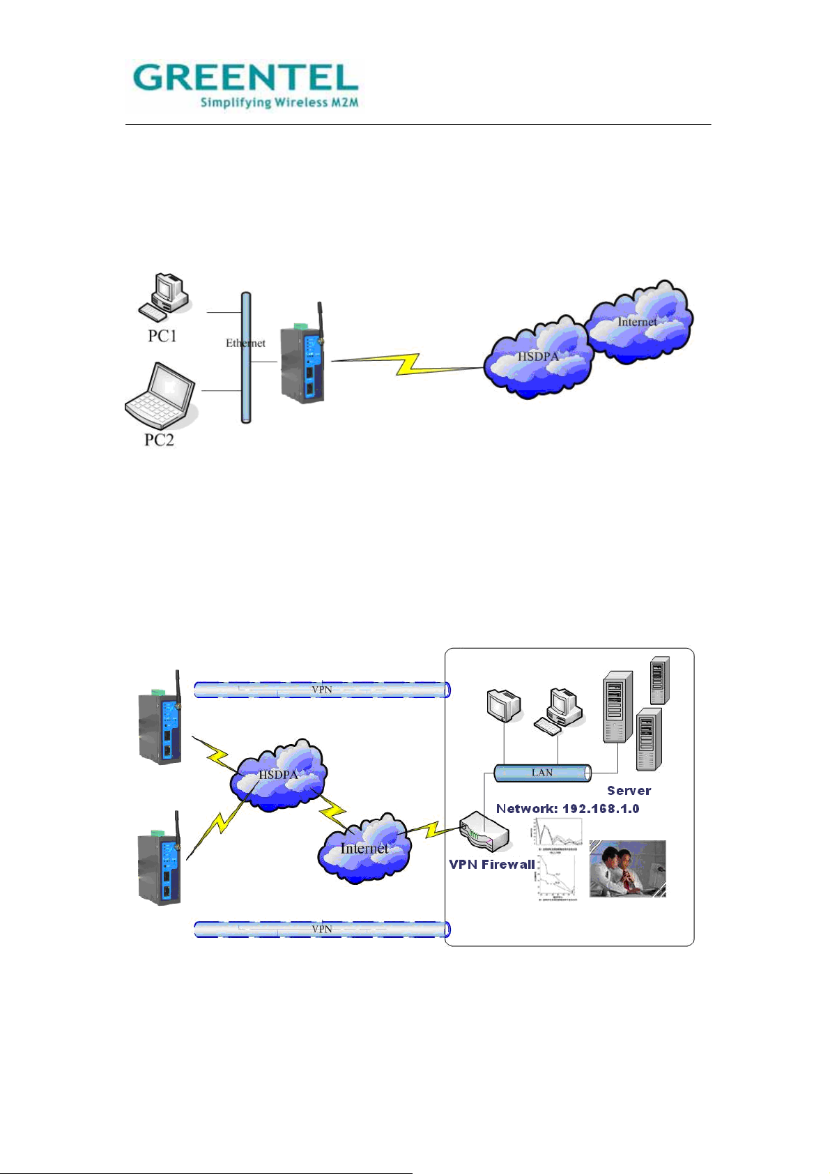
3. Application Introduction
Use as Ordinary Router:
R200 series router can be used as ordinary router, through which users can easily access
into the Internet.
Figure 3.1: Use as Ordinary Router:
VPN Application:
R200 Series has the VPN (Virtual Private Network) function, supporting IPSec and other
VPN protocols. Multiple different LANs can communicate with each other through VPN.
Atypical network structure is as in the following illustration.
Figure 3.2: Use as VPN Router
- 18 -
4. Accessing the Router
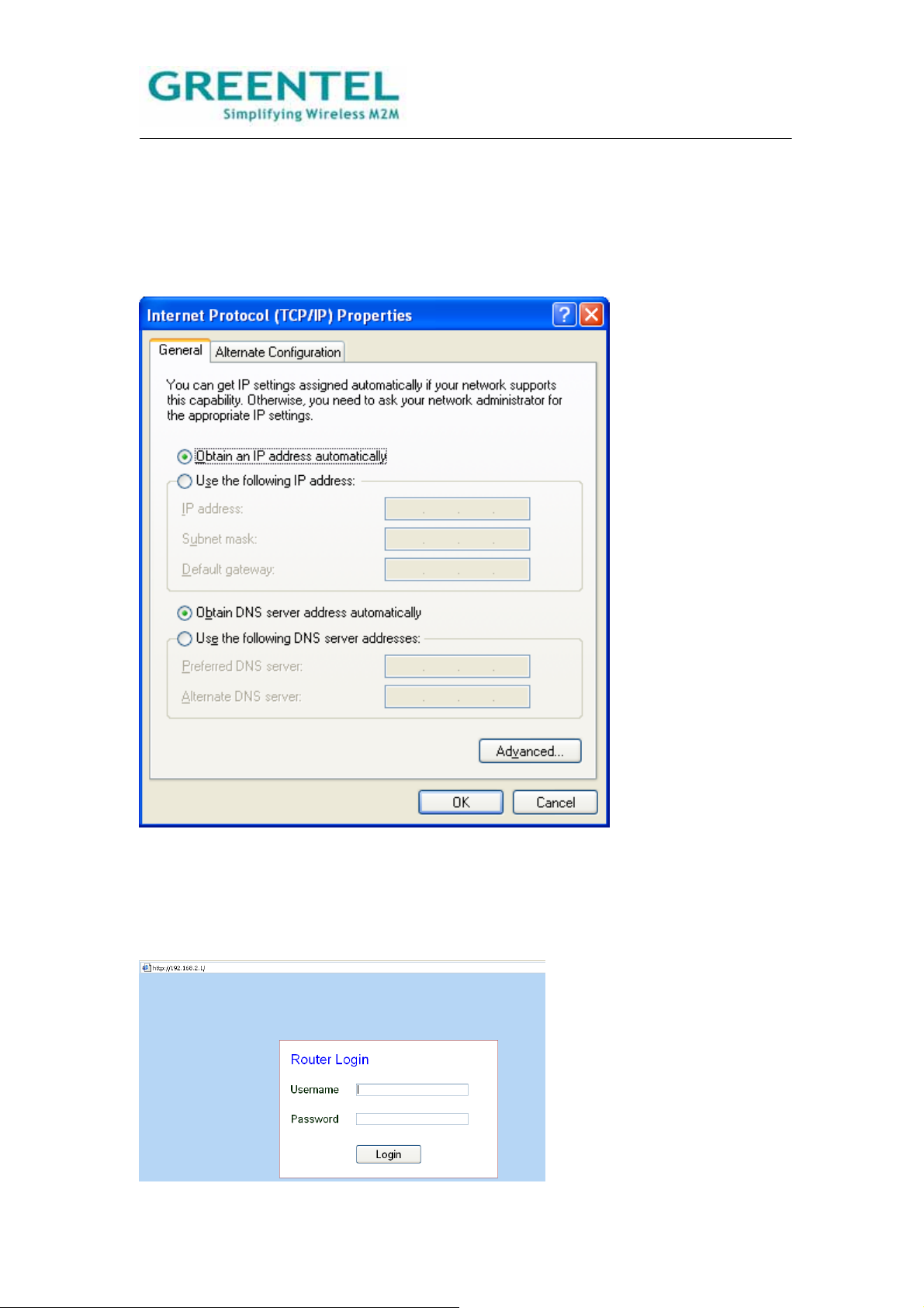
4.1 PC configuration
R200 has been set as DHCP server as default. Please configure your Ethernet connection
as follow, then Router will auto assign IP address 192.168.2.x to your PC:
Figure 4.1 Network Connections->Properties->Internet Protocol (TCP/IP)
4.2 Login
Open Internet Explorer (or other web browsers), enter the IP address of router in the URL
link field, e.g. http://192.168.2.1 (- default IP of R200).
- 19 -

Login
User name: adm
Password: 123456
4.3 System Configuration
System includes 9 groups of system parameter settings: Basic Setup, Time, Serial Port,
Admin Access, System Log, Config Management, Upgrade, Reboot, and Logout.
4.3.1 System -> Basic Setup
This page allows user to adjust basic settings of web configuration, e.g. configuration
language.
Basic Setup
Overall description: to select the language of the configuration interface and to set a
personalized name for the router.
Item Description Default Value
Language Select the language for Web
English
Configurations.
Router Name Give a name to the router. Router
Hostname Give a name to the host
Router
connecting to the router.
- 20 -
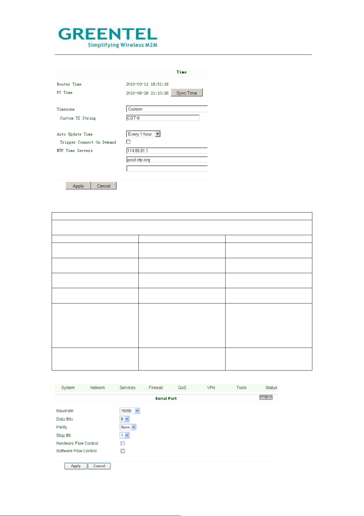
4.3.2 System -> Time
This page allows user to set time related parameters, including router time, timezone, and
time server, etc.
Time
Overall description: to select local timezone and configure NTP to automatically update
time.
Item Description Default Value
Router Time Shows current time on the
1970-01-01 8:00:00
router.
PC Time Shows current time on the
PC.
Timezone Select the local timezone of
Custom
the router’s location.
Custom TZ String Enter local timezone string
CST-8
manually.
Auto Update Time Select whether to
Disabled
automatically update router
time through NTP time
server, can select to auto
update on startup or every
1/2/… hours.
NTP Time Server (Appear
when Auto Time Update is
Set up network time server
address (maximum to 3).
pool.ntp.org
enabled)
4.3.3 System -> Serial port
- 21 -
This page allows user to configure the transmission properties of the serial port of the
router (can be used only under DTU mode).
Serial Port
Overall description: configure the serial port parameters according to its applications.
Item Description Default Value
Baudrate Set the Baudrate of the
19200
serial port.
Data Bits Set the Data Bits of the
8
serial Port.
Parity Set the parity of data
None
transmission of the serial
port.
Stop Bit Set the stop bit of data
1
transmission of the serial
port.
Hardware Flow Control Select whether to enable
Disabled
hardware flow control, select
to enable.
Software Flow Control Select whether to enable
Disabled
software flow control, select
to enable.
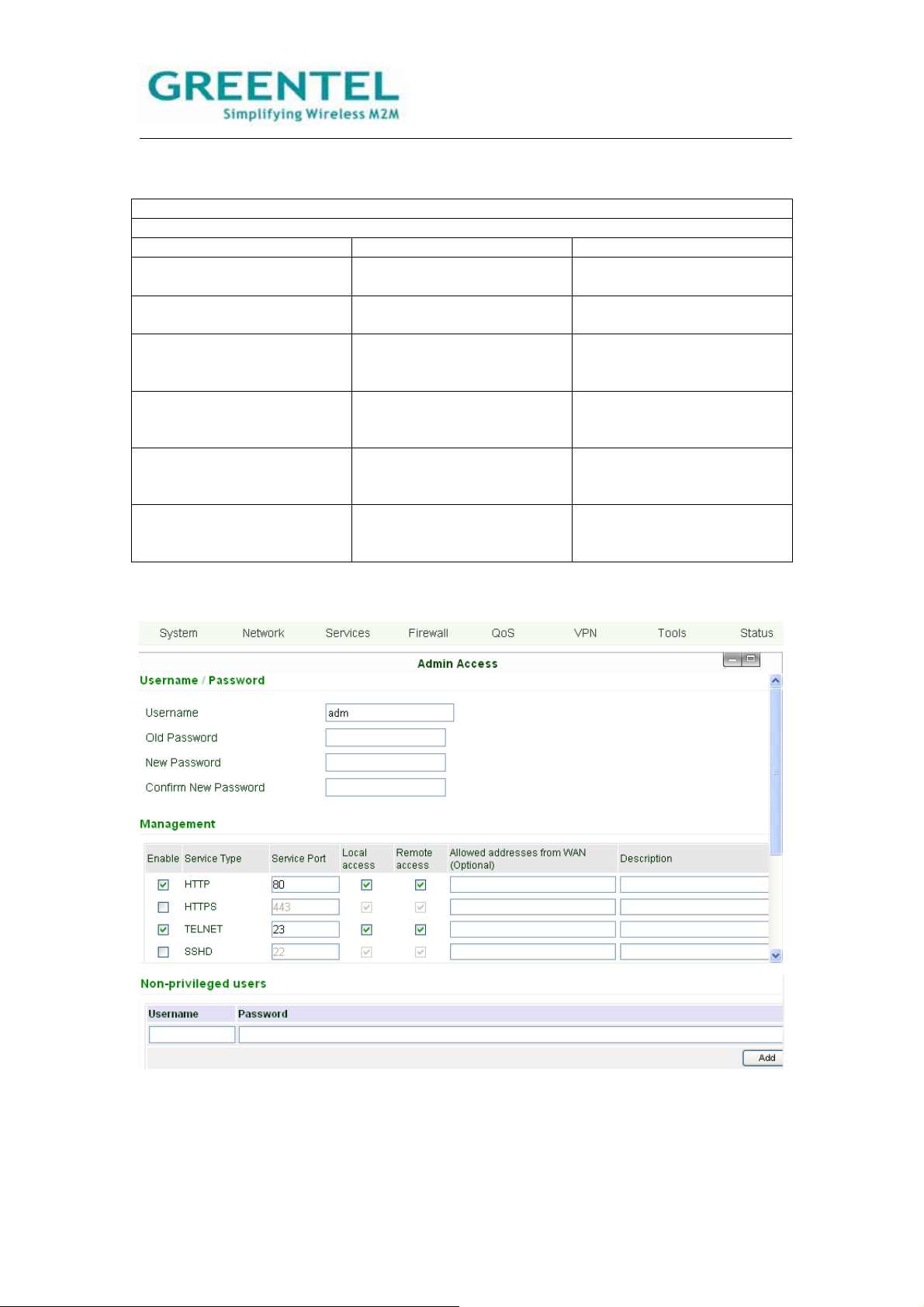
4.3.4 System -> Admin access
- 22 -

This page allows user to set administration access parameters, including username and
password, HTTP/HTTPS/TELNET/SSHD/Console access management, etc.
Admin Access
Overall descriptions:
1. Modify the username and/or password to access the router.
2. Configure management methods: HTTP, HTTPS, TELNET, SSHD, and Console.
3. Set the length of time for login timeout.
Item Description Default
Value
Username / Password
Username Set the Username for web configuration. adm
Old Password Enter the current password that is to be replaced. 123456
New Password Enter the new password for web configuration.
Confirm New
Enter the new password again to double-check the input.
Password
Management – HTTP/HTTPS/TELNET/SSHD/Console
Enable Select to enable a service type. Enabled
Service port Enter respective service ports of the service types: HTTP,
HTTPS, TELNET, SSHD, and Console.
HTTP: 80
HTTPS:
443
TELNET:
23
SSHD: 22
Console:
nil
Local access Select to enable.
Enable—to allow local LAN to access and manage the
router through a service type, e.g. HTTP.
Disabled—not to allow local LAN to access and manage
the router through a service type, e.g. HTTP.
HTTP:
Enabled
HTTPS:
Enabled
TELNET:
Enabled
SSHD:
Enabled
Console:
Enabled
Remote access Select to enable.
Enable-- to allow remote host to access and manage the
router through a service type, e.g. HTTP.
Disabled — not to allow remote host to access and
manage the router through a service type, e.g. HTTP.
HTTP:
Enabled
HTTPS:
Enabled
TELNET:
Enabled
SSHD:
Enabled
Console:
- 23 -

Enabled
Allowed
addresses from
WAN (Optional)
To set allowed address scope of remote host for remote
access. (Only applied to HTTP, HTTPS, TELNET, and
SSHD.)
Description For user to Write down descriptions of the management
options and parameters for future reference, with no
influence to the functioning of the router.
Non-privileged users
Username Non-privileged users could only access to R200 via Telnet,
could not access to R200 via website
Password Non-privileged user password
Other Parameters
Login Timeout Set the length of a period of time over which when there is
no operation on the pages, router will automatically logout.
500
seconds
SMS Control Select to enable disable
SMS Reboot
Command
Enable: user could input any reboot command in English
characters, after receiving the SMS command router will
auto reboot.
Remark: the command should identify uppercase and
lowercase
Send SMS
Command To
COM
Select to enable, after enable router will also output the
SMS Reboot Command to COM port, for example when
user set “Reboot” as reboot command, after receiving
“Reboot” SMS command, router will reboot and output
“Reboot” to COM during the same time
4.3.5 System -> System log
On this page, user can set the router to send system log to a remote log server.
System Log
Overall descriptions: to set IP address and port of remote log server, the router logs will
then be sent and recorded in the remote log server.
Item Description Default Value
Log to Remote System Select to enable sending
Disabled
system log to a remote log
server.
IP Address / Port (UDP) To set the IP address and
Port: 514
port of the remote log server.
- 24 -

4.3.6 System -> Config management
This page allows user to import or backup a router configuration file, a modem driver, or a
Network Provider list, there is also the button to restore the router to factory default
configuration.
Config Management
Overall description:
1. Import a set of user’s pre-stored configuration, or backup current configuration to local
PC.
2. Import the latest Modem driver, or to backup current driver to local PC (- applicable only
to external Modems).
3. Import updated Network Provider list, or backup current list to local PC. Router
manufacturers usually keep updating this list so users are able to choose from all available
mobile networks.
Item Description Default Value
Router Configuration Import a configuration or
backup current one.
Restore default
configuration
Press this button will restore
the router to the factory
default configuration. Note:
It will require a system
reboot to take effect.
Modem Drivers (R2xxU only) Import a driver of the
external modem, or backup
the current one.
Network Provider (ISP) To set in parameters of the
global major Network
Providers -- the APN,
Username, Password, etc.
4.3.7 System -> Upgrade
To upgrade the firmware of the router, go to “System” -> “Upgrade”, click “Browse” to select
a firmware file, and then click on “Upgrade”.
Detail steps are:
Step 1: Click “Browse”, browse to select the firmware file to use then clicks “Open”.
- 25 -

Step 2: Click “Upgrade”, then click “OK” on the pop-up dialog box.
Step 3: The following page will be shown during upgrading:
- 26 -

Step 4: Upgraded successfully. Click “Reboot” to restart the router and have the new
firmware come in effect.
4.3.8 System -> Reboot
- 27 -

When user need to reboot the system, click “System” => “Reboot”.
4.3.9 System -> Logout
To logout, simply click “System” => “Logout”; the system will return to the login page.
4.4 Network
Under Network are 8 configuration items: Dialup, LAN, DNS, DDNS, and Static Route are
items for R2x1 and R2x4, WAN, DMZ Port, Port Mode items are for R2x4 only.
- 28 -

4.4.1 Network -> Dialup
- 29 -

This page is to configure the Dialup port, including Network Provider, username and
password, etc.
Dialup
To setup the parameters for PPP dial-in. Users usually need to set only the basic
parameters and do not need to make changes on the advanced options.
Item Description Default Value
Enable Select to enable PPP dial. Enabled
Shared Connection Select to enable.
Enabled
Enable—to allow local devices that
linked to the Router to access Internet
through it.
Disable—not to allow local devices that
linked to the Router to access Internet.
Network Provider
(ISP)
APN (Not applicable
to CDMA 2000
Series.)
Access Number Enter the access number provided by the
Select the local Network Provider to get
service from.
Enter the APN parameter provided by
the mobile network operator.
mobile network operator.
Customization
Please consult your
Network Provider if
needed.
Please consult your
Network Provider if
needed.
User name Enter the user name provided by the
mobile network operator.
Please consult your
Network Provider if
needed.
Password Enter the password provided by the
mobile network operator.
Please consult your
Network Provider if
needed.
Network Select
Type
Options include: Auto, 2G only, 3G only
Remark: 2G includes GPRS and EDGE;
Auto
3G includes UMTS and HSPA
Band Options include: All, GSM 850, GSM
All
900, GSM 1800, GSM 1900, WCDMA
850, WCDMA 900, WCDMA 1900,
WCDMA 2100
Static IP Select to enable static IP. (You need to
Disabled
first request the Network Provider to
open this service for your account.)
Connection Mode Options include: Always Online, Connect
Always online
On Demand, and Manual.
Connect On Demand includes: Triggered
by Data, Triggered by Call, Triggered by
SMS
Redial Interval To set a length of time over which the
router will redial in case of login failure.
Show Advanced
Options
Select to show advanced options, as are
the following options in this table.
Initial Commands Initial commands are used for advanced
network parameter settings, it is
generally not needed to be filled in.
Dial Timeout Set a length of time over which the dial in
will be timeout. (System will reboot on
dial timeout.)
- 30 -
30 Seconds
Disabled (Below items
are all advanced
options)
Blank
120 Seconds

MTU Set the Maximum transmission Unit. 1500
MRU Set the Maximum receiving Unit. 1500
TX queue length Set transmission Queue Length. 3
Enable IP head
Select to enable IP Head compression. Disabled
compression
Use default
asyncmap
Use peer DNS Select to use the DNS allocated by the
Select to enable asyncmap, an
advanced PPP option.
Disabled
Enabled
mobile operator.
Link Detection
Interval
Link Detection Max
Retries
Set length time for the interval of link
detection.
Set the maximum number of trials for link
detection failure.
30 Seconds
3
Debug Select to enable Debug mode. Enabled
Expert Options To provide extra PPP parameters, which
Blank
users generally do not need to set.
ICMP Detection
Server
Set the ICMP detection server, leaving
blank means not to enable ICMP
Blank
detection.
ICMP Detection
Interval
ICMP Detection
Timeout
Set length time for the interval of ICMP
detection.
Set the length of time over which ICMP
detection will get timeout. (System will
30 Seconds
5 Seconds
reboot on detection timeout.)
ICMP Detection Max
Retries
Set maximum number of trials when
ICMP detection fails.
5
4.4.2 Network -> LAN
This page allows user to configure the LAN ports, setting the IP address, netmask, MTU,
etc.
LAN
Overall description: set the LAN port parameters.
Item Description Default Value
MAC Address Set the MAC address of the
LAN port.
Globally unique MAC
address.
- 31 -

IP Address Set the IP address of the
LAN port.
192.168.2.1
(After changing, please use
the new IP address to login
configuration.)
Netmask Set the Netmask of the LAN
255.255.255.0
port.
MTU Maximum Transmission
Default (1500)
Unit, may choose to use the
default value or to set
manually.
Multi-IP Settings
(May set up to 8 extra IP addresses.)
IP Address Enter the extra IP address of
Blank
LAN port.
Description Write down the description
Blank
of the multiple IP addresses.
4.4.3 DNS
This page allows user to set up the DNS servers, including the primary DNS and secondary
DNS.
DNS Settings
Overall description: set up the DNS servers manually. Usually these are left blank and the
DNS server that’s acquired on dialup will be used; however you need to enter them
manually when you are using static IP on WAN port.
Item Description Default Value
Primary DNS Enter the IP address of your
Blank
network’s Primary DNS
Server.
Secondary DNS Enter the IP address of your
Blank
network’s Secondary DNS
Server.
4.4.4 DDNS
- 32 -

This page allows user to configure the DDNS.
DDNS
Overall description: configure DDNS.
Item Description Default Value
Current Address Display current IP of Router Blank
Service Type Select ISP providing DDNS
Disabled
service.
4.4.5 Static Route
This page allows user to set up static routes by entering the destination, netmask, and
gateway parameters.
Static Route
Overall description: add or remove extra static routes for the router. Generally, users do not
need to set this.
Item Description Default Value
Destination Enter the IP address of
Blank
destination network.
- 33 -

Netmask Enter the Netmask of
255.255.255.0
destination network.
Gateway Enter the gateway of
Blank
destination network.
Interface Select to access destination
Blank
network through LAN port or
WAN port.
Description Write down descriptions of
Blank
the static routes for future
reference.
4.4.6 WAN (R2x4 only)
This page allows user to select WAN port type, includes Static IP, Dynamic Address
(DHCP), ADSL Dialup (PPPoE), Disabled.
Default value is Disabled.
After selecting “Static IP”, or “Dynamic Address (DHCP)”, or “ADSL Dialup (PPPoE)”,
system will disable cellular WAN port connection and popup follow warn windows.
Static IP:
- 34 -

WAN
Overall description: set the WAN port parameters.
Item Description Default Value
Shared Connection Select to enable.
Enabled
Enable—to allow local
devices that linked to the
Router to access Internet
through it.
Disable—not to allow local
devices that linked to the
Router to access Internet.
MAC Address Set the MAC address of the
WAN port.
IP Address Set the IP address of the
WAN port.
Globally unique MAC
address.
192.168.1.29
(After changing, please use
the new IP address to login
configuration.)
Netmask Set the Netmask of the WAN
255.255.255.0
port.
Gateway Set the Gateway of the WAN
192.168.1.1
port.
MTU Maximum Transmission
Default (1500)
Unit, may choose to use the
default value or to set
manually.
Show Advanced Options Select to Enable Disable
ICMP Detection Server Enter the address of ICMP
Blank
detection server.
ICMP Detection Interval Set the interval length of
30 Seconds
ICMP detection.
ICMP Detection Timeout Set the timeout length of
3 Seconds
ICMP detection.
ICMP Detection Retries Set the maximum times of
3
retries in case of ICMP
detection failure.
Multi-IP Settings
(May set up to 8 extra IP addresses.)
IP Address Enter the extra IP address of
Blank
LAN port.
Description Write down the description
Blank
of the multiple IP addresses.
- 35 -

DHCP
ADSL:
- 36 -

4.4.7 DMZ Port (R2x4 only)
This page allows user to set up dedicated DMZ Port.
4.4.8 Port Mode (R2x4 only)
- 37 -

This page allows user to set port mode, user could set 4 Ethernet ports as 4 LAN ports, or
1 WAN port 3 LAN ports, or 1 WAN port, 1 DMZ port and 2 LAN ports.
4.5 Service
The Services tab includes 5 configuration items: DHCP Service, DNS Relay, VRRP, Device
Manager, and DTU settings.
4.5.1 Services -> DHCP Service
This page allows user to configure the DHCP service, including setting the starting and
ending address of IP pool, setting static DHCP, etc.
DHCP Service
Overall description: user need to enable DHCP when your hosts connected to the router
use automatically acquired IP addresses. And with Static DHCP, a host can acquire a
permanent IP addresses from the DHCP server.
Item Description Default Value
Enable DHCP Select to enable DHCP
Enabled
service to acquire IP
addresses automatically
allocated.
IP Pool Starting Address Enter the starting address of
192.168.2.2
IP pool for dynamic
allocation.
IP Pool Ending Address Enter the ending address of
192.168.2.100
IP pool for dynamic
- 38 -

allocation.
Lease Enter the lease valid period
60 Minutes
of the dynamically allocated
IP address.
DNS Edit the IP address of DNS
192.168.2.1
server.
Windows Name Server
(WINS)
Enter the IP address of
Windows Name Server.
0.0.0.0
Static DHCP
(May set up to 20 Static DHCP designations.)
MAC Address Enter the MAC address of a
Blank
host for Static DHCP
designation. (Note: MAC
addresses should be
unique, to avoid conflict with
each other.)
IP Address Enter the permanent IP
192.168.2.2
address designated for the
MAC address.
Host Enter a name for the host. Blank
4.5.2 Services -> DNS Relay
This page allows user to configure the DNS Relay service, designate IP address and
domain name bundles, etc.
DNS Relay
Overall description: user need to enable this service if your hosts connected to the router
are using automatically acquired DNS server.
Item Description Default Value
Enable DNS Relay Select to enable DNS relay
service.
Enabled. (DNS Relay is
automatically enabled when
DHCP service is enabled.)
Static [IP address <=>Domain name] Pairing
(May set up to 20 IP address<=>Domain name pairs.)
IP Address Enter the IP address of the
Blank
IP address <=>Domain
name pair.
Host Enter the domain name of
Blank
the IP address <=>Domain
name pair.
- 39 -

Description Write down the description
Blank
of the IP address
<=>Domain name pair for
future reference.
4.5.3 Services -> VRRP
This page is to configure VRRP function.
VRRP
Overall description: to configure VRRP.
Item Description Default Value
Enable Select to enable VRRP Disabled
Group ID Select a Group ID 1-255 to
1
label router group.
Priority Set a priority level within
1-254.
Advertisement Interval Set the advertisement
10 (The larger number, the
higher priority.˅
60 seconds
interval.
Virtual IP Set a virtual IP Blank
Authentication Type Select none to bypass or
password authentication.
None (Enter the password if
choose Password
Authentication.)
4.5.4 Services -> Device Manager
- 40 -

This page allows user to configure the Device Manager service, including setting the
vendor, device ID, and Device Manager server address.
Device Manager
Overall description: Device Manager client end connects to remote Device Manager
server, for users to manage the router and devices connected to the router remotely.
Item Description Default Value
Enable Select to enable Device
Disabled.
Manager service.
Vendor Choose Vendor. Default
Device ID Enter the device ID to label
Serial number of R200
the device.
Server Enter the address of the
Blank
Device Manager service.
Port Enter the port of the Device
9010
Manager service.
Login Retries Set the number of times to
3
retry for login failure.
Heartbeat Interval Set time length for heartbeat
120
interval.
Packet Receiving Timeout Set time length for data
Blank
packet receiving timeout.
Packet Transmit Retries Set number of times to retry
Blank
when data packet receiving
fails.
Query SMS Interval Query SMS interval 24
Trust Phone List Trust mobile phone list Blank
4.5.5 Services -> DTU
- 41 -

This page is to configure the DTU function, including selecting the protocol, work mode,
and setting DTU server, etc.
DTU
Overall description: to realize common DTU functions.
Item Description Default Value
Enable Select to enable DTU
Disabled.
function.
DTU Protocol Select Transparent, DC,
Transparent
Modbus-Net-Bridge or
Virtual-Serial
Protocol Select UDP or TCP protocol. UDP protocol
Work Mode Select client end or server
Client
end.
Frame Interval Frames interval 100mseconds
Serial Buffer Frames Serial port buffer frames 4 Kbytes
Multi-Server Policy Select the multi-server
Parallel
policy from Parallel or Poll
Min Reconnect Interval Minimum reconnect interval 15
Max Reconnect Interval Maximum reconnect interval 180
DTU ID Enter the ID of DTU. Blank
4.6 Firewall
The Firewall configurations include Basic, Filtering, Port Mapping, Virtual IP Mapping, DMZ,
and MAC-IP Bundling.
4.6.1 Firewall -> Basic
This page allows user to configure the basic settings of Firewall, including firewall policy,
Ping filtering, and multicast filtering, etc.
- 42 -

Firewall – Basic
Overall description: set the basic rules of firewall.
Item Description Default Value
Default Filter Policy Select Accept or Block. Accept
Block Anonymous WAN
Requests
Filter Multicast Select to enable the Filter
Select to filter PING
requests.
Not enabled
Enabled
Multicast function.
Defend DoS Attack Select to enable Defend
Enabled
DoS
Attack.
4.6.2 Firewall -> Filtering
This page is to configure access filters with parameters like protocol type, source address,
etc.
Filtering (May set up to 50 filters.)
Overall description: filter data packets passing through the router according to their
protocol, source/destination addresses and ports, to provide a safe intranet environment.
Item Description Default Value
Enable Select to enable the filter. Blank
Proto Select TCP/UDP/ICMP/All. All
Source Enter source address for the
Blank
filter.
Source Port Enter source port for the
Blank
filter.
Destination Enter destination address
Blank
for the filter.
Destination Port Enter destination port for the
Blank
filter.
Action Select Accept or Block. Accept
Log Select to enable, so system
Disabled
will make the log of filtering.
Description Write down descriptions of
Blank
the
filtering parameters for
future reference.
- 43 -

4.6.3 Firewall -> Port Mapping
This page allows user to set up portmaps, entering the source and internal address and
port to map each other.
Port Mapping (May set up to 50 rules.)
Overall description: also called Virtual Server. With portmaps set, an external host will be
able to access a designated port on the internal host of designated IP.
Item Description Default Value
Enable Select to enable portmap. Disabled.
Source Enter the source IP address
0.0.0.0/0
of the portmap.
Service Port Enter the service port of the
8080
portmap.
Internal Address Enter the internal IP address
Blank
of the portmap.
Internal Port Enter the internal port of the
8080
portmap.
Log Select to enable system to
Not enabled
log
portmap activities.
Description Write down descriptions of
Blank
each portmap settings for
future reference.
4.6.4 Firewall -> Virtual IP Mapping
This page allows user to set up virtual IP mapping, by entering the router’s virtual IP, the
range of source IP, etc.
- 44 -

Virtual IP Mapping (May set up to 50 virtual IP mappings.)
Overall descripton: map the IP addresses of the router and internal hosts to their virtual IP
addresses respectively. Without changing IP allocation of intranet, hosts from extranet can
access internal hosts by their virtual IPs. This function is often used together with VPN.
Item Description Default Value
Virtual IP for Router Enter the virtual IP address
Blank
for the router.
Source IP Range Enter the range of source IP
Blank
address.
Virtual IP Enter the virtual IP. Blank
Real IP Enter the real IP
Blank
corresponding to the virtual
IP.
Log Select to enable system to
Disabled
log virtual IP mapping
activities.
Description Write down descriptions of
Blank
each virtual IP mapping
settings for future reference.
4.6.5 Firewall -> DMZ
This page allows user to set up a DMZ host and the source IP address restriction rules.
DMZ
Overall description: setting a DMZ will provide more safety to your intranet.
Item Description Default Value
Enable DMZ Select to enable DMZ. Disabled
DMZ Host Enter the address of the
Blank
DMZ host.
Source Address Restriction Set restriction rules of
Blank
source addresses.
(Optional)
4.6.6 Firewall -> MAC-IP Bundling
- 45 -

This page allows user to set up MAC-IP bundles.
MAC-IP Bundling
(May set up to 20 MAC-IP bundles.)
Overall description: when the firewall default policy in basic settings is set as
‘Block’, only devices set in MAC-IP Bundling list can access the Internet.
Item Description Default Value
MAC Address Enter the MAC address of
Blank
the device.
IP Address Enter the IP address to be
192.168.2.2
bundled with the MAC
address.
Description Write down descriptions of
Blank
each MAC-IP bundle
settings for future reference.
4.7 QOS
Under the QoS tab, there is simply the Basic Settings of QoS.
On this page, user can set the basic parameters for flow control, including the outbound
and inbound bandwidth limits.
QoS
Overall description: control flow amount by setting bandwidth limits of Internet access.
Item Description Default Value
Enable Select to enable flow
Disabled
control.
Outbound Limit: Max
Bandwidth
Inbound Limit: Max
Bandwidth
Set the maximum limit for
outbound bandwidth.
Set the maximum limit for
inbound bandwidth.
100000kbit/s
100000kbit/s
4.8 VPN
- 46 -

We will introduce IPSEC client only in this part, for further PPTP, L2TP, GRE, OpenVPN
and CA certificate technical support, please contact with us.
4.8.1 VPN -> IPSEC Basic Setting
This page allows user to configure the basic parameters of IPSec VPN, including NAT
Traversal, data Compression, Debug, etc.
IPSec VPN Basic Settings
Overall description:
1. Select whether to enable NATT, this is usually set as enabled unless it’s confirmed there
is no NAT router in the network. To maintain the connection of VPN tunnel, you also need to
set an appropriate length of NATT interval.
2. Select whether to enable data compression and debug mode.
Item Description Default Value
Enable NAT-Traversal
(NATT)
Keep Alive Time Interval of
NATT
Select to enable
NAT-Traversal (NATT).
Set the time length of
interval to keep
Enabled
60 Seconds
NAT-Traversal alive
- 47 -

Enable Compression Select to enable data
compression.
Debug Select to enable debug
mode.
4.8.2 VPN -> IPSEC Tunnels
Click “Add” to go to the “Edit IPSec Tunnel” page.
Enabled
Disabled
- 48 -

This page is to configure the IPSec tunnel parameters, including basic parameters, Phase
I parameters, Phase II parameters, etc.
IPSec Tunnel
Overall description: configure IPSec tunnel.
Item Description Default Value
Show Advanced Options Select the box to have
Disabled
advanced
options shown.
Basic Parameters
Tunnel Name Give a name for the tunnel. IPSec_tunnel_1
Destination Address Enter the IP/domain name of
Blank
the opposite end of VPN.
Startup Modes Select from: Auto Activation,
Auto Activation
Data Triggering, Passive,
and Manual Activation
Negotiation Mode Select Main mode or
Aggressive mode.
Main mode
Remarks: Generally, you
should select Main mode
here.
IPSec Protocol (Advanced
Select ESP or AH protocol. ESP
Option)
IPSec Mode (Advanced
Option)
Tunnel Type Select from 4 types:
Select Tunnel Mode or
Transport Mode.
Tunnel Mode
Subnet – Subnet
Host-Host,
Host-Subnet,
Subnet-Host,
Subnet-Subnet.
Local Subnet Set the local IPSec
192.168.2.1
protection subnet.
Local Netmask Set the netmask of the local
255.255.255.0
IPSec protection subnet.
Remote Subnet Set the protection subnet on
Blank
the opposite end of IPSec.
Remote Netmask Set the netmask of the
255.255.255.0
protection subnet on the
- 49 -

opposite end of IPSec.
Phase I Parameters
IKE Policy Select 3DES-MD5-96 or
3DES-MD5-96
AES-MD5-96.
IKE Lifetime Set the lifetime of IKE. 86400 Seconds
Local ID Type Select from FQDN,
IP Address
USERFQDN, and IP
Address.
Local ID
(Applicable only for FQDN
Enter the ID according to
selected ID type.
Blank
and USERFQDN IDs)
Remote ID Type Select from FQDN,
IP Address
USERFQDN, and IP
Address.
Remote ID
Applicable only for FQDN
Enter the ID according to
selected ID type.
Blank
and USERFQDN IDs)
Authentication Type Select Share Key or
Shared Key
Certificate.
Key
(Displayed when
Set up the shared key of
IPSec VPN.
Blank
Authentication Type is set as
‘Shared Key’˅
Phase 2 Parameters
IPSec Policy Select 3DES-MD5-96 or
3DES-MD5-96
AES-MD5-96.
IPSec Lifetime Set the lifetime of IKE. 3600 Seconds
Perfect Forward Serecy
(PFS) (Advanced Option)
Select from None,
GROUP1, GROUP2, and
GROUP5.
None
(This setting should match
with the server end.)
Link Detection Parameters (Advanced Options)
DPD Time Interval Set the interval length of
60 Seconds
DPD.
DPD Timeout Set the timeout length of
180 Seconds
DPD.
ICMP Detection Server Enter the address of ICMP
Blank
detection server.
ICMP Detection Interval Set the interval length of
30 Seconds
ICMP detection.
ICMP Detection Timeout Set the timeout length of
5 Seconds
ICMP detection.
ICMP Detection Retries Set the maximum times of
3
retries in case of ICMP
detection failure.
- 50 -

4.8.3 VPN -> GRE Tunnels
4.8.4 VPN -> L2TP Clients
- 51 -

4.8.6 VPN -> L2TP Server
4.8.7 VPN -> PPTP Clients
- 52 -

4.8.8 VPN -> PPTP Server
- 53 -

4.8.9 VPN -> OpenVPN Tunnels
- 54 -

4.8.10 VPN -> OpenVPN Advanced
4.8.10 VPN -> Certificate Management
- 55 -

4.9 Tools
Tools tab include 3 groups of configurations: PING, Traceroute and Link Speed Test.
4.9.1 Tools -> PING
This page provides the Ping tool: enter host, count and packet size, Ping the host to test
the connection.
PING
Overall description: a tool to Ping from the router to extranet.
Item Description Default Value
Host Enter the address of the
Blank
host to Ping.
Ping Count Enter the count (i.e. times)
4
to PING.
Packet Size Set the packet size of PING. 32 Bytes
Expert Options To enter advanced settings
Blank
of Ping.
4.9.2 Tools -> Traceroute
- 56 -

On this page, user can enter a host address and related settings to check the route
directing to this host.
Traceroute
Overall description: to trace routing problems in the network.
Item Description Default Value
Host Enter the destination host
Blank
address for the tracing.
Maximum Hops Set maximum hops for the
20
tracing.
Timeout Set the timeout length for
3 Seconds
the tracing.
Protocol Select ICMP or UDP. UDP
Expert Options To enter advanced settings
Blank
for the tracing.
4.9.3 Tools -> Link Speed Test
On this page, user can test upload and download link speed.
4.10 Status
- 57 -

Under Status tab are 6 groups of configurations: System, Modem, Network Connections,
Route Table, Device List, and Log.
4.10.1 Status -> System
This page shows basic information of the system status: name, model, version, router time,
PC time (- click “Sync Time” to have the router’s time sync with PC), up time, CPU load,
and memory consumption status.
4.10.2 Status -> Modem
This page allows user to check real-time status of the built-in Cellular Module (R2xxHHW
or R2xxGC only) or 3G USB modem (R2xxUU only).
- 58 -

4.10.3 Status -> Network Connections
This page displays the connection status of WAN, Dialup, and LAN ports.
The WAN connection part displays the MAC address, connection type, IP address,
netmask, gateway, DNS, MTU, status, and connection time. With DHCP dynamic
allocation, you may apply to renew or release the lease.
The Dialup connection part displays the connection type, IP address, netmask, gateway,
DNS, MTU, status, and connection time. And you may connect/disconnect the link by
clicking the corresponding buttons.
The LAN connection part displays the MAC address, IP address, netmask, MTU, and DNS.
4.10.4 Status -> Route Table
This page displays the current route table, including the destination, netmask, gateway,
metric, and interface of the routes.
4.10.5 Status -> Device List
- 59 -

Device List is shown on this page, the device information include the interface, MAC
address, IP address, host, and lease.
4.10.6 Status -> Log
This page lets user review the system logs. user may select to view 20/50/…/all recent
lines of the log, or have the logs ranked by information Level (Info/Debug/Alert), Time,
Module, or Content.
user may clear logs, download log file, or download System Diagnosing Data with the
buttons on the page bottom. The default refreshing rate of this page is every 1 minute,
which user may change by stopping the refreshing and select a desired rate from the
pull-down list on the left.
- 60 -

5. How to upgrade new firmware
Please refer to section 4.3.7 Upgrade for upgrade new firmware operation.
- 61 -

6. How to diagnose
When user faced problem during testing, please power off the router, then power on and
keep it running for 3 minutes, go to page “Status -> Log”, download system diagnosing
data and send to Greentel for analyzing.
- 62 -

7. Configure via Telnet
Open command window. (Click “Start” => “Run”, enter “cmd” in the pop-up dialog box to
have DOS window opened.) Enter “telnet 192.168.2.1” (i.e. to connect to R200 when its IP
is 192.168.2.1).
User name: adm
Password: 123456
- 63 -

8. Configure via Serial Port
Connect the computer to the console RJ45 port of R200 with a serial cable, open the
Windows tool – Hyper Terminal.
- 64 -

- 65 -

- 66 -

User name: adm
Password: 123456
- 67 -

9. How to reset to factory defaults settings
9.1 Reset by Software
Press ‘Restore default configuration’ button will restore the router to the factory default
configuration. Note: It will require a system reboot to take effect.
9.2 Reset by Hardware
1. Power off, and then hold pressing reset button, then power on;
2. After Status LED blinking and Error LED on, stop holding reset button;
- 68 -

3. After step 2, Error LED will off;
4. In 30 seconds, please hold pressing reset button until Status and Error LED blinking;
5. Stop hold pressing reset button, and router has restored to factory default.
9.3 Reset by Telnet
1. Login R200 via Telnet
User name: adm
Password: 123456
- 69 -

2. Input “en” and Enter, to login the enable mode.
2. Input “restore” and Enter, then router will restore to factory default.
- 70 -

10. Support
In case you have problems with the installation and use, please address them to the
Technical Assistance Department by e-mail support@greentel.cn.
GREENTEL LIMITED
Address: 11 Daling Rd, Huizhou, China, 516001
WEB: http://www.greentel.cn
EMAIL: info@greentel.cn
Copyright Greentel Limited 2001-2010. All rights reserved.
Subject to alterations without notice.
- 71 -

Annex:FCCRFExposurerequirements:
To maintain compliance with FCC RF exposure requirements, use handset that maintain a 20cm
separation distance between the user's body and the host.
MPE limit for RF exposure at prediction frequency is 0.558mW/cm2 for 850MHz band and
1mW/cm2 for 1900MHz band. The maximum MPE for 850MHz band is 0.333 mW/cm2 and
0.415mW/cm2 for 1900MHz band. It satisfy RF exposure compliance.
This device complies with part 15 of the FCC rules. Operation is subject to the following two
conditions: (1) this device may not cause harmful interference, and (2) this device must accept any
interference received, including interference that may cause undesired operation.
NOTE: The manufacturer is not responsible for any radio or TV interference caused by
unauthorized modifications to this equipment. Such modifications could void the user’s authority
to operate the equipment.
NOTE: This equipment has been tested and found to comply with the limits for a Class B digital
device, pursuant to part 15 of the FCC Rules. These limits are designed to provide reasonable
protection against harmful interference in a residential installation. This equipment generates
uses and can radiate radio frequency energy and, if not installed and used in accordance with the
instructions, may cause harmful interference to radio communications. However, there is no
guarantee that interference will not occur in a particular installation. If this equipment does
cause harmful interference to radio or television reception, which can be determined by turning
the equipment off and on, the user is encouraged to try to correct the interference by one or more
of the following measures:
- Reorient or relocate the receiving antenna.
- Increase the separation between the equipment and receiver.
-Connect the equipment into an outlet on a circuit different from that to which the receiver is
connected.
-Consult the dealer or an experienced radio/TV technician for help
 Loading...