

Greentek 60-150W, 185-300W User Manual
LED SHOEBOX LIGHT INSTRUCTION
Cautions:
1. Can not use the electric generator to test the LED lamp
2. Please abide by related country, regioinal and local law and
regulations when installing this fixture
3. To avoid electrical shock and damage, please do not install the
lights on rainy days
Notices:
1. To prevent from electric shock or fire risk, the installation must be
conducted by operator who has professional electrical knowledge
2. Please wear gloves to avoid injury before installing lamps
3. During or after installation, if there are situations such as
smoke, fire in the wires or lamps, please turn off the power
immediately and notify relevant personnel of an overhaul.
4. This light can be used for outdoor installation
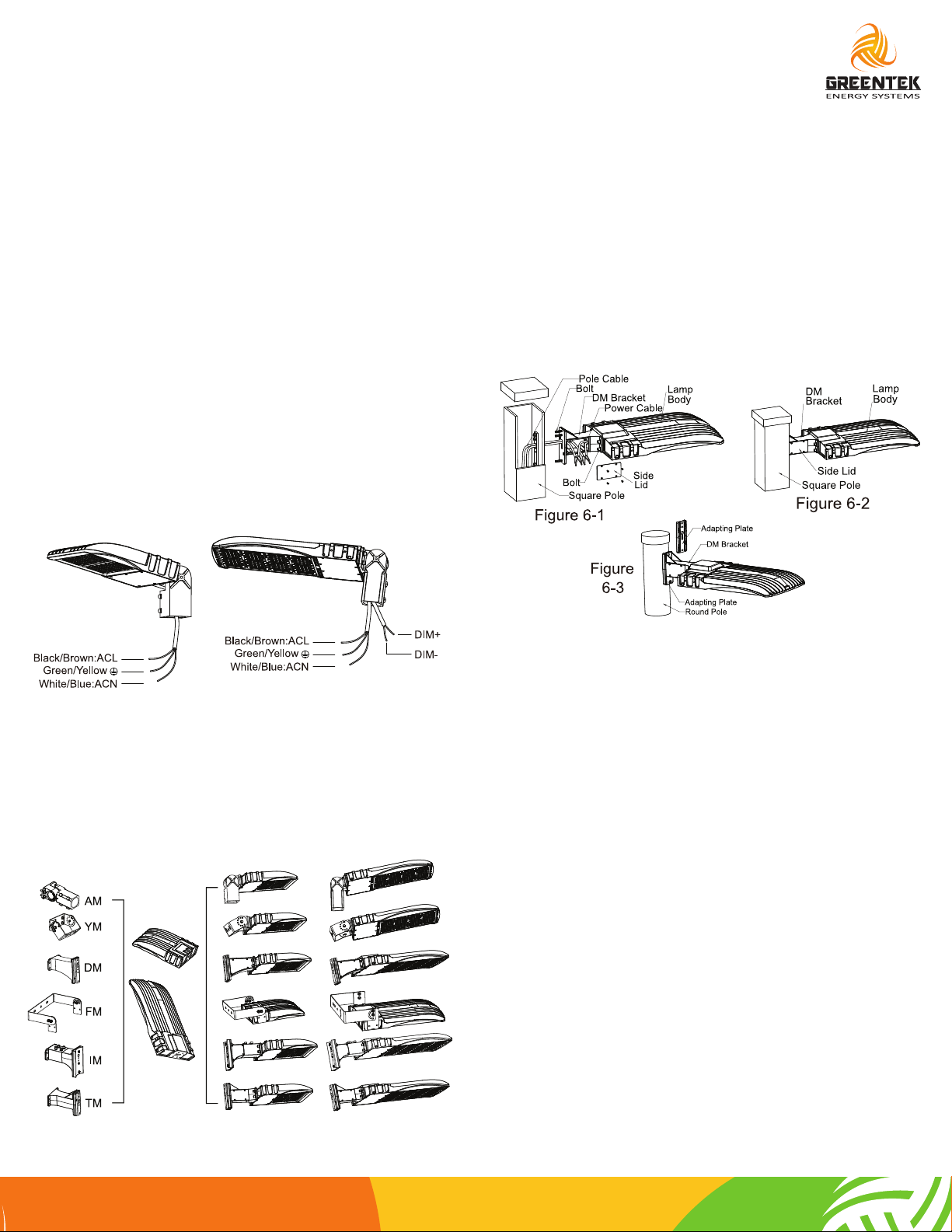
Wiring Diagram:
60-150W
185-300W
Installation VI: TM Mounting Installation Steps:
1. Open the side lid on DM bracket. Let the power cable go
thorugh the DM bracket. Fix the DM bracket to the end of lamp
body by bolt. Let the pole cable go through the DM bracket.
(Figure 6-1)
2. Fix the DM bracket to the square pole by bolt. Connect the
power cable with pole cable, make sure good protection on the
wire connection, and put the wire in the DM bracket; close the
side lid and tighten it, (Figure 6-2) then finish installation
3. Notice: Round pole should be with adapting plate (Figure 6-3)
As for the wire color of DIM+ and DIM-,
please check the lamp label!
Optional Brackets:
There are 6 optional brackets for this fixture. The following is
shoebox fixtures with different brackets:
Notice:
1. 60-150W shoebox light could be with Photocell (built in) and
surge protector. 185-300W shoebox light could be with
Photocell (external), surge protector and microwave sensor,
installation manual won’t change.
2. 185-300W shoebox light could be with 1-10V dimming
function. If you don’t need such function, please don’t take off
the silicon protective cover on wire.
Standard wire
L/live wire: Black\Brown
N/null wire: White\Blue
Ground wire: Green\Yellow-green
Warning/Arertissement:
MIN 75ºC SUPPLY CONDUCTOR
THIS PRODUCT MUST BE INSTALLED IN ACCORDANCE
WITH THE APPLICABLE INSTALLATION CODE BY A
PERSON FAMILIAR WITH THE CONSTRUCTION AND
OPERATION OF THE PRODUCT AND THE HAZARDS
INVOLVED
LES FILS D’ALIMENTATION 75ºC MIN
CE PRODUIT DOIT ÊTRE INSTALLÉ SELON LE CODE
D’INSTALLATION PERTINENT, PAR UNE PERSONNE QUI
CONNAÎBIEN LE PRODUIT ET SON FONCTIONNEMENT
AINSI QUE LES RISQUES INHÉRENTS.
GreentekEnergySystems.com
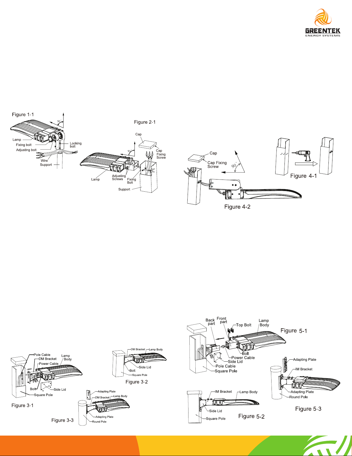
Installation I: ADJUSTABLE FITTER MOUNTING
Installation Steps:
1. Loosen the 4 locking bolts on the slip fitter, connect the wire
correctly and put the wire into pole. Then fasten the locking bolts
between slip fitter and the pole. (Figure 1-1)
2. Loosen the fixing bolts and adjusting bolts, align the fixture to
required angle. Tightn adjusting bolt and fixing bolts after the
angle is confirmed. (Figure 1-1)
Installation II: YOKE MOUNTING
Installation Steps:
1. Loosen cap fixing screw and take cap off. Loosen fixing bolt,
fixed the fixture on the support and tighten fixing bolts. (Figure 2-1)
2. Let the AC wire go through support hole and connected
correctly. Close cap and tighten cap fixing screw after AC cable is
well placed in the support. (Figure 2-1)
3. Loosen adjusting screws, align the fixture to required angle
and fasten the screws. (Figure 2-1)
Installation III: YOKE MOUNTING
Installation Steps:
1. Open the side lid of direct bracket, let the power cable go
through the direct bracket. Fix the direct bracket to the end of
lamp body with bolt. Let the pole cable go through the direct
bracket. (Figure 3-1)
2. Fix the direct bracket to the square pole with bolt. Connect the
power cable to the pole cable, make sure good protection on the
wire connection, and put the wire in the direct bracket; close the
side lid and tighten it, (Figure 3-2) then finish installation.
3. Notice: Round pole should be with adapting plate. (Figure 3-3)
Installation IV: FLOOD MOUNTING
Installation Steps:
1. Use electric drill to drill holes on the poles or suspended walls.
(The hole pitch should be according to the actual application of
products , the hole size should be same as the screw the user has).
(Figure 4-1)
2. Put the installation bracket on the pole position, and using
screws and nuts to fix the light tight, adjusting to the desired light
angle. (Figure 4-2)
3. Connect the wire of the lamp to the mians according to local
wiring rules, make good protection on the connection, put the
wire into the pole, cover thepole cover, tighten the side screws.
(Figure 4-2)
Installation V: INSERT MOUNTING
Installation Steps:
1. Take off the top bolt on IM bracket. Open side lid on the back
part after take IM bracket apart into the front part and the back
part. Let the power cable go through the front part of the IM
bracket. Fix the front part to the end of lamp body with bolt. Let
the pole cable go through the back part of the IM bracket, Fix the
back part of the IM bracket to the pole with bolt. (Figure 5-1)
2. Let the power cable in the front part of the IM bracket go
through the back part. Sheath the front part to the back part and
fix them with top bolt. Connect the power cable with back part,
Close the side lid and tighten it, (Figure 5-2) then finish installation.
3. Notice Round pole should be with adapting plate. (Figure 5-3)
GreentekEnergySystems.com
 Loading...