

Page 1
PROTECT
Owner’s Manual
Page 2

Welcome
Thank you for purchasing purePower PROTECT. We encourage you to read through
this Owner’s Manual before moving forward with the installation process.
If you have any questions or concerns, please visit www.GreenTechEnv.com
Contents
Warnings ................................................................2
Installation Procedure ..................................................... 3
Test Procedures & Troubleshooting .......................................... 4
Specications & Ratings ................................................... 5
Warranty Information ...................................................6 - 7
Warnings
1. Opening the unit without prior permission from GreenTech Environmental will void
its warranty coverage. Contact your purePower Dealer with any questions.
2. Apply this unit to 250VAC 50/60 Hz 1-Phase residential load only.
(120VAC Line to Neutral)
3. The unit must be mounted vertically using the four mounting holes.
4. The unit must be installed by a licensed electrician in compliance with
local electrical code.
5. This unit must be connected directly to a dedicated 2-pole 20 AMP circuit
breaker. Do not, under any circumstances, hard-wire install without a
dedicated breaker.
6. Do not install on 3-Phase Systems.
2
Page 3
Copyright © 2016 GreenTech Environmental | All Rights Reserved
You Will Need
1. A dedicated 2-pole 20 AMP circuit breaker.
2. Appropriate tools, including conduit.
NOTE: (Conduit & Nut included. 1/2 Straight Connector. 1 - 20” Conduit.)
3. A licensed electrician for installation.
Mounting purePower PROTECT
1. Inspect the exterior of the unit to ensure that it has not been damaged in
transit. Ensure that the front label is intact and that the wires protruding
from the unit have not been damaged.
2. Mount the unit to a wall near the power panel. Lengthening of the wires to
accomodate mounting the unit further away from the panel than the current
wiring allows may be necessary. As a general rule, the length of the wires
should be kept as short as possible and electricians should follow standard
electrical code regarding adding wire to the unit. When mounted, the
indication lights should be visible.
3. Run conduit (according to code) between the conduit connector on the box,
and the power panel, and feed the connection cables through the conduit
into the power panel.
Installation Procedures
1. If possible, de-energize the power panel prior to connection of the unit.
2. Install the circuit breaker onto the power panel.
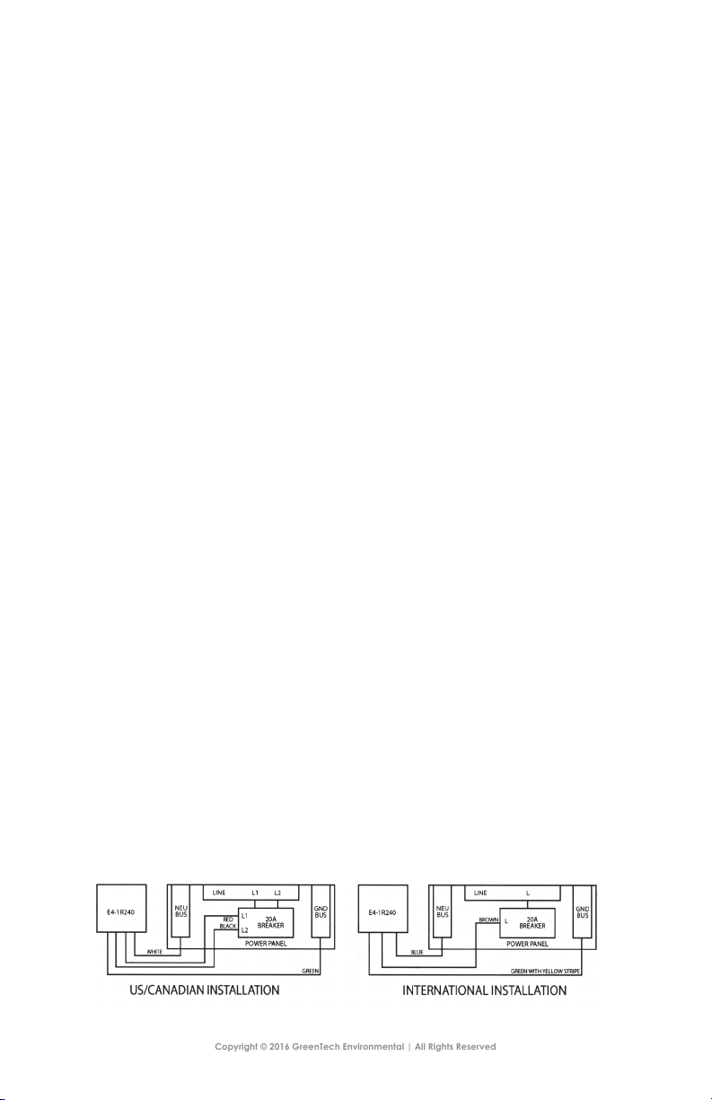
3. Connect the L1 (RED) and the L2 (BLACK) wires to the circuit breaker, the
Ground Cable (GREEN) to the ground bus, and the Neutral Cable (WHITE)
to the Neutral Bus, as shown in the diagram below.
3
Page 4

Test Procedures
1. Energize the Power Panel.
2. Close the Circuit Breaker leading to the unit.
3. Check in Line 1, Line 2, and Power Lights are on. If not, de-energize the unit
and ensure proper wire connections.
NOTE: For International Appliances, only 1 Indicator Light may be on.
4. Check the Power, Ground, and Neutral Wire Connections.
5. Keep these instructions near the unit for future use.
Troubleshooting
1. In the event one or both of the “LINE” LEDs are not on, check the breaker.
This indicates power from one or both of your power lines is not getting to
the unit.
2. If one or both of the “MOV” LEDs are not on, your unit has encountered a surge
and has been damaged. Please go to www.GreenTechEnv.com and request a
warranty replacement.
4
Page 5

Copyright © 2016 GreenTech Environmental | All Rights Reserved
Specications & Ratings
VOLTAGE: 250 V AC, 1-Phase, 50/60Hz
CONFIGURATION: 2-Wire Plus Ground and Neutral
CAPACITANCE: 30µf
LINE CURRENT: 3.77 A at 250V AC
KVAR RATING: .6 at 250V AC
Dimensions
5
Page 6

purePower PROTECT
Limited Warranty & Equipment Protection Coverage
10 Year Limited Warranty
Your purePower PROTECT (“UNIT”) is warranted by GreenTech Environmental (“GTE”) to be free from all
defects in material and workmanship in normal residential use for a period of ten (10) years from the
date of purchase. This warranty is granted only to the original purchaser (“BUYER”) and is subject to the
following provisions.
If UNIT is damaged by a power surge or fails to work (“MALFUNCTION”) within ten (10) years of purchase,
GTE will, at its sole discretion, repair or replace UNIT. As a matter of warranty policy, GTE will not refund the
BUYER’s purchase price.
This warranty covers damage caused by a power surge, dened as an electrical transient or spike on the
AC power lines, including those caused by indirect lightning, subject to the EXCLUSIONS herein.
The above remedy is the sole remedy under this warranty, whether based on contract, tort, including
negligence or otherwise. Unless this warranty is expressly renewed or extended by GTE, any repaired or
replaced part of UNIT shall be warranted to the original purchaser only for the length of the unexpired
portion of the original warranty.
EXCLUSIONS: Warranty is void if UNIT is determined by GTE, at its sole discretion, to have been: (a)
subjected to improper storage, installation, operation, accident, abuse or negligence of any part other
than GTE; (b) damaged due to a direct lightning strike or sustained overvoltage condition; (c) installed
by anyone other than a contractor insured to perform electrical installations; (d) installed or serviced in
a manner other than according to the manufacturer’s instructions; (e) out of working order immediately
prior to the EVENT or MALFUNCTION.
6
Page 7

Copyright © 2016 GreenTech Environmental | All Rights Reserved
$100,000 Equipment Coverage
Subject to the provisions detailed below, GTE guarantees to BUYER that UNIT will protect connected
residential electrical equipment from a power surge or spike (“EVENT”) originating from your electrical
utility or your local electrical system, subject to the EXCLUSIONS herein. If UNIT fails to protect said
equipment, GTE will cover the repair or replacement cost, at GTE’s sole discretion, up to $2,500 per item
damaged and no more than a total of $100,000 per event.
This coverage applies only to the BUYER of a new unit and is non-transferable. Coverage is secondary to
any insurance, warranties, or other coverages in effect at the time, including the BUYER’s homeowner’s
insurance policy. If a submitted claim is determined by GTE, at its sole discretion, to be valid, GTE will
pay up to the deductible of the homeowner’s insurance or the cost of the damage, whichever is less.
Coverage is limited to ten (10) years from the original purchase of UNIT.
EXCLUSIONS: Coverage does not apply to equipment that is determined by GTE, at its sole discretion,
to have been: (f) damaged by an act of God or subjected to improper storage, installation, operation,
maintenance, accident, misuse, abuse or negligence of any part other than GTE; (g) damaged due to
a direct lightning strike or sustained overvoltage condition; (h) disconnected from the electrical system
protected by UNIT at the time of the EVENT; (i) lacking valid UL® or CSA® approval; (j) intended or used
for commercial purposes or in a commercial environment. (k) intended or used for life support, medical
equipment, or home security. (l) This coverage does not cover reimbursement for labor, transportation,
gaining access, removal, installation, temporary power, or any other expenses which may be incurred in
connection with repair or replacement of UNIT or damaged equipment.
REGISTRATION: BUYER must register their UNIT with GTE within thirty (30) days of purchase. BUYER should visit
http://www.GreenTechEnv.com/warranty or call +1 (800) 957-1136 and provide all required information.
Failure to register UNIT within thirty (30) days voids warranty and coverage detailed herein.
FILING A CLAIM: Call +1 (800) 957-1136 to notify GTE within thirty (30) days of the EVENT or UNIT failure.
BUYER must provide, via email or postal mail, their full name, complete address including zip-code (no
PO boxes allowed), dated proof of purchase for UNIT and any damaged electrical equipment involved
in the claim, a letter explaining the EVENT or UNIT failure, a copy of any insurance claim affecting UNIT
or damaged equipment with detailed information regarding the damaged items and the cost of repair
or replacement. GTE has the right to inspect UNIT, the electrical system in which UNIT was being used,
and any damaged electrical equipment involved in the claim. Before shipping anything to GTE, BUYER
must contact GTE to obtain a Return Merchandise Authorization (“RMA”) number. The RMA number must
be clearly written on any shipments before their arrival at GTE. BUYER is responsible for all shipping costs
incurred in relation to a claim. Failure to initiate a claim within thirty (30) days of the EVENT or UNIT failure
voids warranty and coverage detailed herein.
IN NO EVENT SHALL GTE BE LIABLE FOR SPECIAL, CONSEQUENTIAL, OR INCIDENTAL DAMAGES. GTE GRANTS
NO OTHER COVERAGE OTHER THAN THAT PRESENTED HEREIN, EXPRESS OR IMPLIED, INCLUDING, BUT NOT
LIMITED TO, THE IMPLIED WARRANTIES OR CONDITIONS OF MERCHANTABILITY AND FITNESS FOR A PARTICULAR
PURPOSE. SOME STATES OR JURISDICTIONS DO NOT ALLOW THE EXCLUSION OF EXPRESS OR IMPLIED
WARRANTIES, SO THIS ABOVE EXCLUSION MAY NOT APPLY TO YOU. IN THAT EVENT, SUCH WARRANTIES
ARE LIMITED IN DURATION TO THE LIMITED WARRANTY PERIOD. SOME STATES OR JURISDICTIONS DO NOT
ALLOW LIMITATIONS ON HOW LONG AN IMPLIED WARRANTY LASTS OR THE EXCLUSION OR LIMITATION OF
INCIDENTAL OR CONSEQUENTIAL DAMAGES, SO THE ABOVE LIMITATIONS AND/OR EXCLUSIONS MAY NOT
APPLY TO YOU. NOTHING IN THIS COVERAGE DOCUMENT AFFECTS ANY STATUTORY RIGHTS OF CONSUMERS
THAT CANNOT BE WAIVED OR LIMITED BY CONTRACT. THIS COVERAGE GIVES YOU SPECIFIC LEGAL RIGHTS,
AND YOU MAY ALSO HAVE OTHER RIGHTS WHICH VARY FROM JURISDICTION TO JURISDICTION. THIS LIMITED
WARRANTY AND COVERAGE SHALL BE GOVERNED BY THE LAWS OF THE STATE OF TENNESSEE, U.S.A.
COVERAGE IS EFFECTIVE JANUARY 1, 2017 AND IS SUBJECT TO CHANGE WITHOUT NOTICE.
7
Page 8

www.GreenTechEnv.com
 Loading...