

Page 1

Owner’s Manual
Page 2

2
Page 3

TABLE OF CONTENTS
About pureHeat GARAGE & PATIO ..............................4
Features ....................................................4
Specications ...............................................4
Product Contents ............................................5
Unit Diagram ................................................6
Important Instructions ........................................7
Unit Setup - Floor Stand .................................... 8 - 9
Unit Setup - Wall/Ceiling Mount ...............................10
Control Panel/Remote Diagrams ..............................11
Using pureHeat GARAGE & PATIO .............................12
Maintenance/Cleaning/Storage/Troubleshooting ................13
Warranty ...................................................14
RECORDS
Please record the name and phone number of your Dealer.
Name: __________________________________________________________________
Phone #: ________________________________________________________________
Please record the serial number of your pureHeat GARAGE & PATIO.
Serial #: _________________________________________________________________
3
Page 4

ABOUT PUREHEAT GARAGE & PATIO
Thank you fo r your purchase of pu reHeat GARAGE & PATIO. T his heater provides
consi stent warmth to outdoor spaces using carbon infrared heating technology,
warm ing your friends and fa mily di rectly instead of just heating the sur rounding ai r.
pureHeat GARAGE & PATIO can be mounted using easy-to- install bracket, or it can
be placed on an adjustabl e metal stand for mobi lit y. Eith er way, the si lent and
odor les s heating element i s a safe distance from children and pets.
For optimum comfort, three different levels of heat can be produced with almost
no war m- up time. A 24-hour ti mer all ows fo r specic shut-of f time selection, and a ll
features can be adjusted using the included remote control. pureHeat GARAGE &
PATIO is durable, light weight, mai ntenance-free, and can connect to your standard
household electrical outlet.
FEATURES
• High Efficiency Carbon Fiber Heating Element
• 3 Power Modes
• Shut- Off Timer
• 360° Tip -Over Safety
• Floor Stand and Wall Mounting Options
SPECIFICATIONS
Model Number: ......................................... PHGARAGE17A
Power Input: .......................................120VAC/60Hz | 12.5A
Power Usage: ...................................... 500W/1000W/1500W
Heat Output: .................................................5100 BTU
Unit Dimensions: ................................7.6” H x 30.0” W x 3.6” D
Unit Weight: .................................................... 5.7 lb
Stand Dimensions: ..................... 42.8” - 71.5” H x 19.7” W x 19.7” D
Stand Weight: ................................................. 14.7 lb
Warranty: ..................................................... 3 Years
4
Page 5
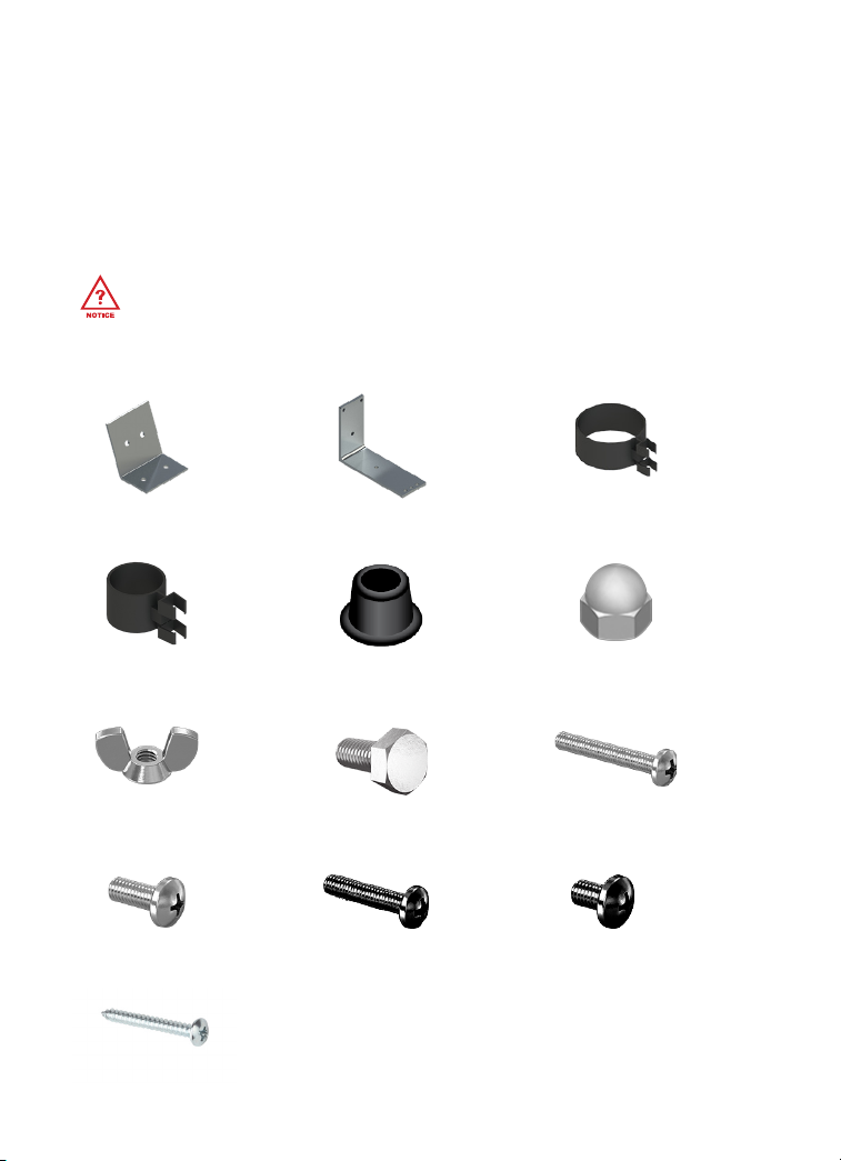
PRODUCT CONTENTS
1 - Owner’s Manual
1 - pureHeat GARAGE & PATIO Heater
1 - Remote Control (Batteries Not Included)
1 - Telescoping Stand
Thread Diameter is denoted in mm by the rst number. (i.e. M5*12 = 5mm diameter)
Screw Length is denoted in mm by the second number. (i.e. M5*12 = 12mm length)
1 - Mounting Bracket 1
1 - Small Cord Clip 1 - Base Cover
2 - Wing Nuts
1 - Mounting Bracket 2
2 - M6*14 Bolts
1 - Stand Base
3 - Cord Clips
1 - Grille Guard
2 - Large Cord Clip
2 - Acorn Nuts
2 - M6*35 Screws
4 - M5*12 Screws
3 - ST4*35 Screws
4 - M6*30 Screws 6 - M5*6 Screws
5
Page 6
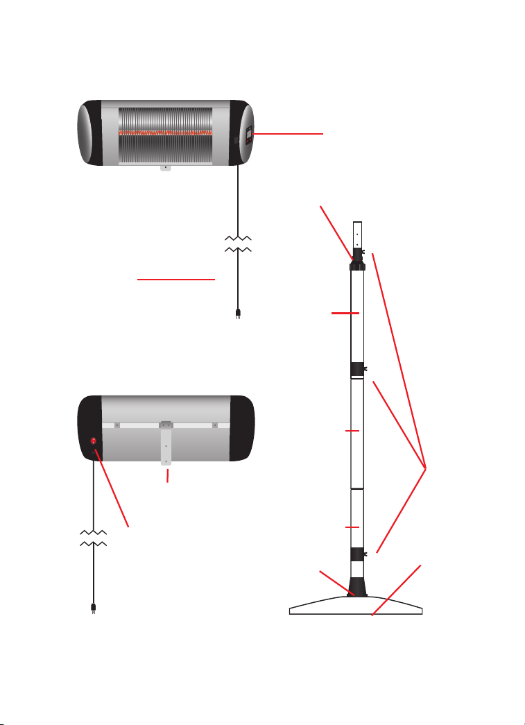
UNIT DIAGRAM
Power Cord
Control Panel
Telescoping Lock
Top Post
Middle Post
Mounting Bracket
Power Switch
Bottom Post
Base Cover
6
Cord Clips
Stand Base
Page 7

IMPORTANT INSTRUCTIONS
When using electrical appliances, basic precautions should always be followed to
reduce the risk of fire, electric shock, and injury to persons, including the following:
• Read all instructions before using this heater.
• This heater is hot when in use. To avoid burns, do not let bare skin touch hot surfaces. If
provided, use handles when moving this heater. Keep combustible materials, such as
furniture, pillows, bedding, papers, clothes, and curtains at least 3 feet (0.9 m) from the
front of the heater and keep them away from the sides and rear.
• Extreme caution is necessary when any heater is used by or near children or invalids and
whenever the heater is left operating and unattended.
• Always unplug heater when not in use. (This item may be omitted if the heater is
provided with a clock-operated switch).
• Do not operate any heater with a damaged cord or plug or after the heater
malfunctions, has been dropped or damaged in any manner. Discard heater, or return
to authorized service facility for examination and/or repair.
• This heater is not intended for use in bathrooms, laundry areas and similar indoor
locations. Never locate heater where it may fall into a bathtub or other water container.
• Do not run cord under carpeting. Do not cover cord with throw rugs, runners, or similar
coverings. Do not route cord under furniture or appliances. Arrange cord away from
trafc area and where it will not be tripped over.
• To disconnect heater, turn controls to off, then remove plug from outlet.
• Connect to properly grounded outlets only.
• Do not insert or allow foreign objects to enter any ventilation or exhaust opening as this
may cause an electric shock or re, or damage the heater.
• To prevent a possible re, do not block air intakes or exhaust in any manner. Do not use
on soft surfaces, like a bed, where openings may become blocked.
• A heater has hot and arcing or sparking parts inside. Do not use it in areas where
gasoline, paint, or ammable liquids are used or stored.
• Use this heater only as described in this manual. Any other use not recommended by the
manufacturer may cause re, electric shock, or injury to persons.
• Always plug heaters directly into a wall outlet/receptacle. Never use with an extension
cord or relocatable power tap (outlet/power strip).
• SAVE THESE INSTRUCTIONS
• This heater is for use on 120 volts. The cord has a plug as shown at (A) in the gure below.
An adapter as shown at C is available for connecting three-blade grounding-type plugs
to two-slot receptacles. The green grounding lug extending from the adapter must
be connected to a permanent ground such as a properly grounded outlet box. The
adapter should not be used if a three-slot grounded receptacle is available.
Grounding Pin
(A) (B)
Adapter
Metal Screw
(Grounded)
7
Page 8

UNIT SETUP - Floor Stand
INSPECT THE UNIT FOR DAMAGE BEFORE SETUP OR USE.
1. Begin by connecting the Bottom Post
(Post with a Flat Base) to the Base, using
the provided Four (4) M6*30 Screws.
2. Slide the Base Cover over the connected
post to cover the screws and then slide
One (1) Large Cord Clip over the post.
3. Place the Middle Post (Optional for extra
17.5” height) onto the Bottom Post and
fasten them together using Three (3) M5*6
Screws on the sides. Slide the remaining
(1) Large Cord Clip over the post.
4. Place the Large and Small Cord Clips
on the Top Post then place the Post
onto the Middle Post (or Bottom Post if
you want a lower height) and fasten
them together using Three (3) M5*6
Screws on the sides.
8
Page 9

UNIT SETUP - Floor Stand
5. Use Two (2) M6*14 Bolts and Two (2)
Acorn Nuts to combine Top of Bracket
1 (Long End) to the Bottom of Bracket 2
(Short End) .
6. Use Two (2) M6*35 Screws and Two
(2) Wing Nuts to install the Front of
Bracket 2 (Long End) to the rear
of the Telescoping Post.
7. Use Two (2) M5*12 Screws to install
Bracket 1 (Short End) to the rear of
the Heater Body.
8. Use the Two (2) remaining M5*12 Screws
to mount the Grille Guard to the rear of
the Heater Body. The Grill Guard should
extend over the front of the unit.
x2
x2
9. Loosen the Telescoping Lock and slide
the pole and unit up or down to your
desired height, then re-tighten the
Telescoping Lock.
9
Page 10

UNIT SETUP - Wall Mount
FOR YOUR SAFETY, READ ALL IMPORTANT INSTRUCTIONS (PAGE 7) AND USAGE (PAGE 13)
BEFORE USING YOUR PUREHEAT PATIO.
HEATER MUST BE MOUNTED HORIZONTALLY OR THE TIP OVER SAFETY SWITCH WILL ENGAGE
AND THE UNIT WILL NOT OPERATE.
1. Ensure the desired mounting location can t the unit in a horizontal orientation and is
near an outlet but free from electrical cables, communication lines, and pipes that
could be damaged by excessive heat.
2. If needed, pre-drill your wall and insert
3 Wall Anchors. Use Bracket 2 as a
template for hole placement.
3. Use Two (2) M6*14 Bolts and Two (2) Acorn
Nuts to combine Top of Bracket 1 (Long
End) to the Bottom of Bracket 2 (Short End) .
4. Use (3) ST4*35 Screws and fasten the
Mounting Bracket to the Wall in a
vertical orientation. Use the top hole
and the outside holes on the bottom.
5. Use Two (2) M5*12 Screws to install the
Mounting Bracket to the rear of the
Heater Body.
x2
x2
Mounting Surface
10
Page 11

CONTROL PANEL/REMOTE DIAGRAMS
Control Panel
Power Mode/Timer Hours
88
24
Function ON LED
Remote
Power Mode 1 (500W)
Power Mode 3 (1500W)
Mode Button
Power Button
LED
MODE TIMER
P1 P2
P3 TIMER
11
Timer Button
Power Mode 2 (1000W)
Timer Button
Page 12

USING PUREHEAT GARAGE & PATIO
READ ALL IMPORTANT INSTRUCTIONS (PAGE 5) BEFORE USING YOUR PUREHEAT GARAGE & PATIO.
Power
pureHeat GARAGE & PATIO starts in Standby Mode when rst turned on. The unit has
power but is not actively heating.
To turn the unit on, toggle the Power Switch to “ - ”.
Modes
Changing the Power Mode increases the Heat Output.
P1 is the Lowest Heat Output Mode and P3 is the Maximum Heat Output Mode.
P1 Press the Mode Button once to change to Power Mode 1(500W).
P2 Press the Mode Button again to change to Power Mode 2 (1000W).
P3 Press the Mode Button a third time to change to Power Mode 3 (1500W).
Pressing the Mode Button once more puts the unit in Standby Mode again.
Timer
While the unit is active, a timer can be set to turn the unit OFF after a desired amount of hours.
Press the Timer Button to change the amount of hours before the unit will shut off. The
time will increase in 1 Hour Increments, up to 24 Hours.
12
Page 13

MAINTENANCE
Your pureHeat GARAGE & PATIO should be maintenance free for many years, but
sometimes the unexpected happens. If you have any trouble with your unit, contact
GreenTech Environmental by phone or visit www.GreenTechEnv.com/Support.
CLEANING
TURN PUREHEAT GARAGE & PATIO OFF AND DISCONNECT FROM THE OUTLET BEFORE CLEANING.
To extend the life of your pureHeat GARAGE & PATIO, perform regular cleanings with a
damp cloth. Do not disassemble the unit; clean only the exterior.
STORAGE
To prevent accidents, or save some space, store your pureHeat GARAGE & PATIO in a
cool, dry place. Per form a cleaning and allow it to dry before packing it away.
TROUBLESHOOTING
Unit Fails to Turn On
First, check to ensure your unit is plugged in and the power switch on the rear is in the
“on” position. If these have already been checked, your Tip-Over Safety Switch may be
stuck. Tilt the unit 90° to the side and then back into a standing position. Set your heat
level to P3 to make sure it is working.
If your unit still won’t turn on, contact GreenTech Environmental Customer Service.
www.GreenTechEnv.com/Support
13
Page 14

LIMITED WARRANTY INFORMATION
Your pureHeat GARAGE & PATIO (Product) is warranted to be free from all defects in material and
workmanship in normal household use for a period of 3 Years from date of purchase. The warranty is
granted only to the original purchaser. The warranty is subject to the following provisions:
Any damages or malfunctions caused by negligence, abuse, or use not in accordance with the Product
Owner’s Manual are not covered by this warranty. Likewise, any defects or damages caused by
unauthorized service or the use of other than Genuine pureHeat Parts are not covered.
All shipping charges are the responsibility of the purchaser. GreenTech Environmental will, at its option,
repair or replace a defective Product or part(s) for the Product that is/are covered by this warranty.
As a matter of warranty policy, GreenTech Environmental will not refund the customer’s purchase price.
OBTAINING WARRANTY SERVICE
To obtain warranty service you must return the defective product along with proof of purchase to the
pureHeat Authorized Service Center. All shipping costs submitted under this Warranty shall be borne by
purchaser. Unless this Warranty is expressly renewed or extended by pureHeat, any repaired or replaced
part of unit shall be warranted to the original purchaser only for the length of the unexpired portion of the
original warranty. For the location of the nearest pureHeat Authorized Service Center or for other service
information, please visit us online or contact Customer Service at:
www.GreenTechEnv.com/Support
Before any product is sent for service, the customer should contact the pureHeat Service Center to
obtain a Return Merchandise Authorization (RMA) Number. This RMA Number should be clearly written on
the box before shipping. All components/parts including the remote (if applicable), manuals, and original
packaging should be included in the return if available.
FURTHER LIMITATIONS AND EXCLUSIONS ARE AS FOLLOWS
Any warranty that may be implied in connection with your purchase or use of the Product, including any
warranty of merchantability or any warranty for Fitness For A Particular Purpose is limited to the duration
of this warranty. Some states do not allow limitations on how long an implied warranty lasts, so the above
limitations may not apply to you.
Your relief for the breach of this warranty is limited to the relief expressly provided above. In no event
shall pureHeat be liable for any consequential or incidental damages you may incur in connection with
your purchase or use of the Product. Some states do not allow the exclusion or limitation of incidental or
consequential damages, so the above limitation or exclusion may not apply to you.
This Warranty gives you specic legal rights, and you may also have other rights which vary from state to state.
REGISTRATION
Please register your Product within 10 days of purchase by visiting www.GreenTechEnv.com/Warranty.
Registering your new pureHeat product entitles you to the most up-to-date pureHeat warranty
and promotion information.
14
Page 15

15
Page 16

OM Revision: GTE-pureHeat_GARAGE&PATIO-OwnersManual-190116
www.GreenTechEnv.com
16
 Loading...