

Page 1

Owner’s
Manual
Introduction (Thanks / Warnings / Records)
Features / Benefits
Controls / Diagrams
Initial Setup
Operations
Maintenance
LCD Reminders
Disassemby / Assembly
Cleaning
Troubleshooting
Consumer Information
Specifications
Warranty Information
(Placement / Settings)
3
4
5
8
9
9
9
10
12
13
14
14
14
www.GreenTechEnv.com
Page 2

Page 3
Introduction
Page 3
Thanks
Welcome to a better, healthier environment!
The GT3000 is one of the most advanced air
purication systems on the market today.
Incorporating photo catalytic oxidation
technology, high level negative ionization, safe
levels of ozone, and electrostatic ltration,
the GT3000 reduces particles and inactivates
microbes providing a cleaner, healthier
environment for you and your family.
The GT3000 is designed to provide years of
trouble-free service when properly maintained.
This manual will guide you through proper
operation of the purier as well as maintenance
procedures. When properly cared for, some
parts of the unit will need replaced periodically.
Replacement parts can be obtained from your
authorized distributor or directly from GreenTech
Environmental (www.GreenTechEnv.com).
Warnings
WARNING: Never operate the unit near
a heat source, open ame, or ammable/
combustable uids.
WARNING: Do not operate the unit
unless the following are properly
installed: PCO CELL, PURIFICATION
PLATE, REAR FILTER ASSEMBLY (with
all three pieces in place), and the REAR
COVER.
WARNING: Eye damage may result from
directly viewing the light produced by
the lamp inside of this unit. Eye damage
occurs after 20 minutes of continuous
exposure one inch from grill.
CAUTION: Never adjust the setting
to exceed the square footage of the
ventilated space being treated.
Thank you for purchasing the GT3000 by
GreenTech Environmental.
CAUTION: Do not use AWAY MODE in
occupied spaces. Short term exposure
to ozone levels above .05 ppm can cause
temporary adverse reactions.
CAUTION: The unit should be powered
off and the POWER CORD should
be disconnected whenever cleaning/
disassembling/reassembling/servicing.
Records
Purchase Date: ________________________________________________________________________
Model Number: ________________________________________________________________________
Serial Number: ________________________________________________________________________
Distributor Name: _____________________________________________________________________
Distributor Phone: ____________________________________________________________________
Page 4
Features / Benets
Page 4
The GT3000 is one of the most advanced and
most versatile whole house air purication
systems on the market today.
Using four advanced technologies, the GT3000
helps to eliminate Odors, smoke, pollen, dust,
bacteria, mold, carbon monoxide, pet dander,
viruses, and much more. Noticeable pollution is
eliminated in as little as 15 minutes, and the most
difcult pollution in as few as 24 hours.
Unlike other air puriers that have only one or
two ways of eliminating pollution, the GT3000
has four advanced technologies to destroy
pollution from the air, embedded in walls,
ceilings, oors, carpets, furniture, clothing,
on countertops and other surfaces. These
technologies help to sanitize everything in the
house and reduces or eliminates all odors,
including cigarette smoke, mildew, cooking
odors, and more.
The advanced variable frequency drive fan system
of the GT3000 runs quietly. In addition, the
GT3000 is very low maintenance and requires
no lter replacement. You simply clean the
electrostatic honeycomb and mesh lter with
running water! The GT3000 is ideal for any
room in your home where airborne and surface
pollution may be present.
Needlepoint Ionization: The GT3000
generates a continuous stream of millions of
negative ions that circulate throughout the home.
These ions charge particles of dust, dander,
bacteria and viruses; causing them to attract
other particles and clump together. As more
and more particles come together, they become
heavier, making them easier to pull into the
homes furnace lter or just fall to the oor to be
vacuumed up. Unlike HEPA lters that can lter
out particles of .5 microns or larger, the ionizer in
the GT3000 can reduce ultra-ne particles, even
nano-particles, that are much more dangerous
than the larger particles you can see. This means
your family breathes easier with less particles in
the breathing space, less exposure to bacteria,
mold and virus particles as well.
Scalable Purication: In High Mode the
purication plate is activated to generate
activated oxygen to assist in breaking down mold,
bacteria, and other biological contaminates which
cause odors. By setting the purier based upon
the area to be treated, just the right amount of
purication is produced to keep the home fresh
and clean. For faster cleanup an “Away Mode”
feature which has a auto-shutoff programmable
timer allows for maximum output to be used
when the room or home is unoccupied.
Four Advanced Technologies
Advanced Photo Catalytic Oxidation (PCO)
Cell: The PCO technology in the GT3000 not
only destroys biological contaminates traveling
through the cell, but it produces a purifying
plasma which breaks down odors, mold, bacteria
and viruses. Photo Catalytic Oxidation reactors
have been proven to reduce dangerous pathogens
by over 99% in 24 hours or less. The process is
molecular disassociation, which doesn’t just cover
up the source, it actually breaks the molecule
down. The result at the end of the breakdown
process is Carbon Dioxide and Water Vapor.
Copyright © 2010 GreenTech Environmental | All Rights Reserved
CAUTION: Do not use AWAY MODE in occupied
spaces. Short term exposure to ozone levels above
.05 ppm can cause temporary adverse reactions.
Electrostatic Filtration: An advanced
electrostatic lter is included with the GT3000
to help keep the purier clean while at the same
time lter out particles which clump together
thanks to the needlepoint ionization. Unlike
expensive HEPA lters, the electrostatic lter is
washable and can be used over and over again.
Additional Information
Model: . . . . . . . . . . . . . . . . . . . . . . . . Whole House
Maximum Coverage Area: . . . . . . . . . . 3000 sq. ft.
Warranty: . . . . . . . . . . . . . . . . . One Year Warranty
Page 5
Controls / Diagrams
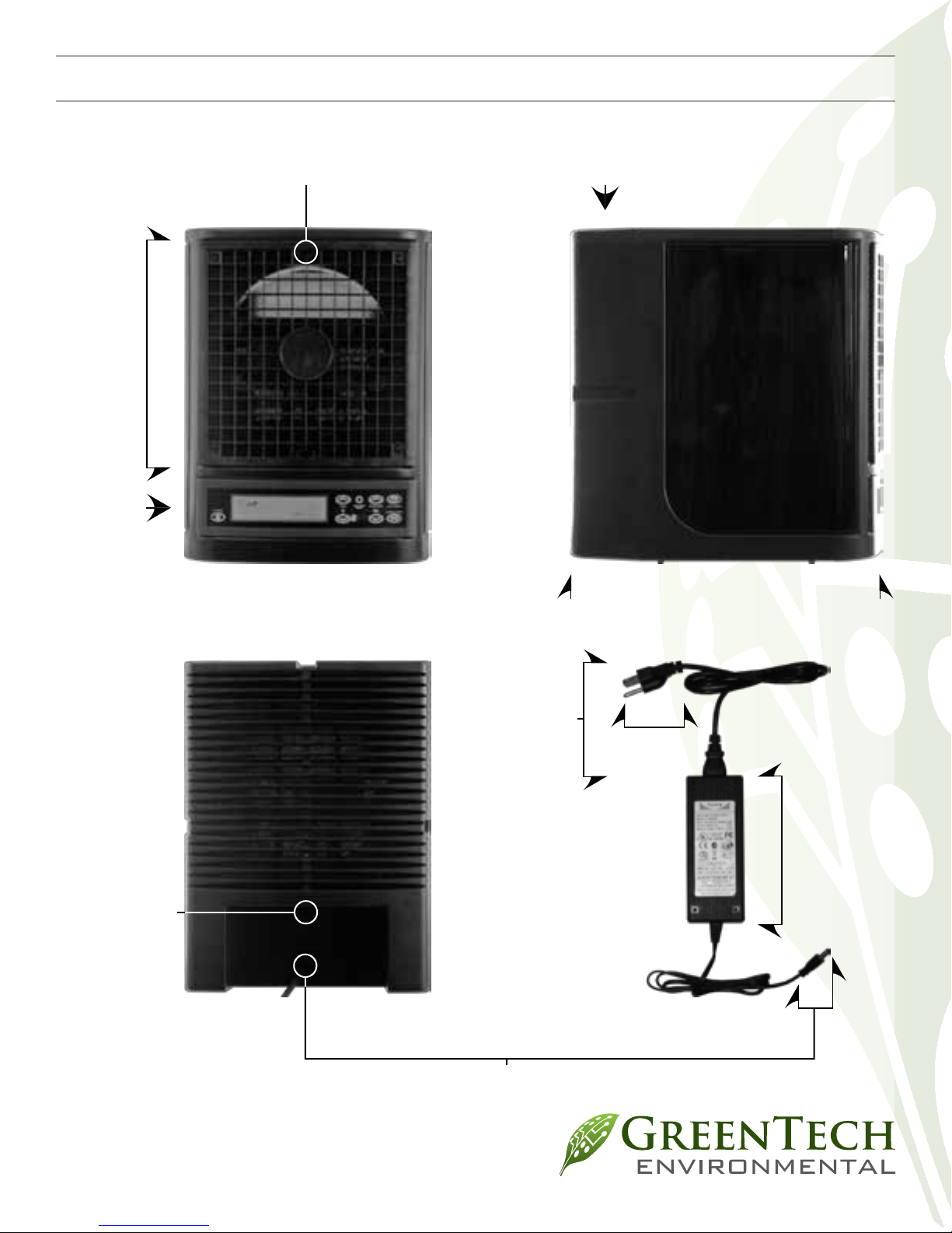
Control
Unit Exterior
Page 5
Front
Grille
Panel
Ionization
needle
Rear
Cover
Unit
Rear
Unit
Front
Rear
Cover
Screw
Power
Cord
Power
Plug
Power
Adapter
Power
Adapter
Plug
Page 6

Control Panel
Controls / Diagrams Continued
Page 6
Power
Button
Mode
Normal
Fan Level
Indicator
Technology
Indicator
NORMAL
Control
Fan Level
Indicator
Reminder Reset
Button
Fan
Infrared
Reciever
Purifier
Warning
Away Mode
Toggle
Purifier
Control
Normal/
High
Toggle
Square
Footage
Indicator
Away
Mode
Fan Level
Indicator
AREA MUST BE
UNOCCUPIED
Away mode
Warning
Normal Mode
Indicator
Away Mode
Timer
Away mode
Indicator
HRS
AWAY
High
Mode
Purifier Capacity
Indicator
LCD
Reminders
PURIFIER SETTING
MUST NOT EXCEED
SIZE OF AREA
REPLACE PLATE
REPLACE PCO CELL
PERFORM CLEANING
2
FT
HIGH
High mode
Indicator
Purifier Capacity
Indicator
Copyright © 2010 GreenTech Environmental | All Rights Reserved
LCD Reminders
Page 7

Page 7
Unit Rear
Filter Removed
Unit Rear
Filter Assembly
Power
Button
Remote
POWER SLEEP
Thumbscrews
Assembly
Power Cord
Connector
Sleep
Toggle
Brass
Filter
Purifier
Control
Normal/
High Mode
Toggle
AWAY
MODE
FAN
PURIFIER
NORMAL
HIGH
See Owner’s Manual for complete
operating instructions
Fan
Control
Away Mode
Toggle
PCO Cell
Thumb Nuts
Purification
Plate
PCO Cell
Power Connector
Power Cord
Connector
Page 8

Initial Setup
Page 8
Page 8
Ideal Placement
When selecting a place for the unit within the
environment there are some things to keep in
mind. Find a location in the room(s) as far away
from the HVAC air return duct as possible, so
that the purication produced by the unit is
optimally circulated. Place the unit on top of a
bookshelf, shelf, or mounting bracket as high
as possible leaving twelve to twenty-four inches
between the unit and the ceiling. Make sure that
there is as much space as possible in front of the
unit and at least six inches behind the unit so it
can intake air. Never place an operating unit on
the oor.
Initial Settings
Before using the unit you will need to nd the
area (square footage) of the environment. Take
into account all rooms which have doors that
normally remain open to the environment as the
purication that the unit produces does not ow
readily through closed doors. The unit can cover a
maximum of 3000 square feet.
For example: Suppose you have a 2500 square
foot house. The living room is attached to the
kitchen, three bedrooms, and a laundry room.
The kitchen and three bedroom’s doors remain
open the majority of the time but the laundry
room and den usually remain closed off from the
rest of the house. Together, the laundry room and
den have a combined area of 500 square feet. The
area of your environment would be 2000 square
feet.
After you have established the placement of your
unit and the area of the environment, connect
the POWER CORD to the POWER ADAPTER.
Connect the POWER ADAPTER PLUG to the
unit, plug the POWER PLUG into the wall outlet,
turn the unit on (See “CONTROLS”), and set it to
NORMAL mode.
Leave the unit on NORMAL mode for at least
24 hours to begin with. After 24 hours, set the
unit to HIGH mode and set the square footage
to 250 square feet. Then, every 8-12 hours,
gradually increase the square footage setting of
the unit until it is set to the square footage of the
ventilated space.
Using the purier at a setting less than the square
footage of the area being treated is acceptable
and may be desirable when the environment is
relatively free of pollutants.
Copyright © 2010 GreenTech Environmental | All Rights Reserved
Page 9

Operations & Maintenance
Page 9
Turning the Unit On
Press the POWER BUTTON on the CONTROL
PANEL or REMOTE to turn the unit on. Unit will
initially be set to “NORMAL MODE”
Dimming the Display
Press the SLEEP TOGGLE button on the
REMOTE to toggle the display backlight through:
bright, dim, and off.
Normal Mode
Press NORMAL/HIGH button until “NORMAL”
is shown in the lower right of the DISPLAY.
Use FAN UP/DOWN buttons to control the fan
speed.
High Mode
Press NORMAL/HIGH button until “HIGH” is
shown in the lower right of the DISPLAY.
Use PURIFIER UP/DOWN buttons to set the
square footage on the DISPLAY. (See “INITIAL
SETUP: INITIAL SETTINGS”)
Use FAN UP/DOWN buttons to control the fan
speed.
CAUTION: Never adjust the setting to exceed
the square footage of the ventilated space being
treated.
Away Mode
Press the AWAY MODE button and verify that
“AWAY” is shown in the lower right of the
DISPLAY.
Press AWAY MODE to add two hours per press to
the AWAY MODE TIMER.
Select 2:00, 4:00, 6:00, or 8:00 hours or press
AWAY MODE again after 8:00 hours to switch
the unit back to NORMAL MODE.
LCD Reminders
Replace Plate
The PURIFICATION PLATE has reached the
end of it’s useful life and must be replaced.
Contact your distributor or GreenTech
Environmental (www.GreenTechEnv.com)
to order a replacement. Once a replacement
has been obtained, follow the instructions in
”DISASSEMBLY / ASSEMBLY” to replace the old
PURIFICATION PLATE with your new one.
Replace PCO Cell
The PCO CELL has reached the end of it’s
useful life and must be replaced. Contact your
distributor or GreenTech Environmental
(www.GreenTechEnv.com) to order a
replacement. Once a replacement has
been obtained, follow the instructions in
”DISASSEMBLY / ASSEMBLY” to replace the old
PCO CELL with your new one.
Perform Cleaning
The 30 day operation cycle between cleanings has
passed and the unit requires a complete cleaning.
Follow the instructions in “CLEANING” and then
see “RESETTING REMINDERS” to reset the
reminders. The PERFORM CLEANING reminder
will appear again after 30 days of operation.
CAUTION! The unit should be powered off and
the POWER CORD should be disconnected
whenever cleaning/reassembling/servicing.
Resetting Reminders
After replacing the PURIFICATION PLATE or
the PCO CELL the corresponding reminders will
reset themselves. After performing a cleaning
of the unit (See “CLEANING”) you should reset
the reminders by holding down the RESET
REMINDERS button on the CONTROL PANEL
of the unit. The reminder has been reset when
PERFORM CLEANING no longer appears.
CAUTION: Do not use AWAY MODE in occupied
spaces. Short term exposure to ozone levels above
.05 ppm can cause temporary adverse reactions.
Page 10

Disassembly / Assembly
DISASSEMBLY:
Page 10
You will need a #1 PHILLIPS SCREWDRIVER.
WARNING! Do not operate the unit unless
the following are properly installed: PCO
CELL, PURIFICATION PLATE, REAR FILTER
ASSEMBLY (with all three pieces in place), and
the REAR COVER.
CAUTION! The unit should be powered off and
the POWER CORD should be disconnected
whenever cleaning/disassembling/reassembling/
servicing.
1. Turn the unit off. (See “CONTROLS”)
2. Removing The Power Cord:
(a) Unplug POWER CORD from wall outlet.
(b) Remove POWER ADAPTER PLUG from
rear of unit.
3. Clean the exterior of the unit if necessary (See
“CLEANING: UNIT EXTERIOR”).
4. Removing The Rear Cover:
(a) Using your SCREWDRIVER, remove
the REAR COVER SCREW from the REAR
COVER (above the POWER CORD PORT).
Place the REAR COVER SCREW where you
will nd it easily during reassembly.
(b) Squeeze the tabs on both sides of the
REAR COVER (where the grooves are)
until they release and tilt the REAR COVER
upwards until the top tab releases. Clean if
necessary with compressed air or a damp
cloth, then set the REAR COVER aside.
5. Removing The Filter Assembly:
(a) Remove BRASS THUMBSCREWS from
the top corners of the FILTER ASSEMBLY.
Place BRASS THUMBSCREWS where you will
nd them easily during reassembly.
(b) Grasp the top of the FILTER ASSEMBLY
and tilt the FILTER ASSEMBLY away from
the unit. Clean if necessary (See “CLEANING:
FILTER ASSEMBLY”) and set the FILTER
ASSEMBLY aside.
6. Removing The Purication Plate:
(a) Grasp the PURIFICATION PLATE on the
ceramic between the black arrows and gently
pull the PURIFICATION PLATE out of the
grooves on the sides. Clean if necessary (See
“CLEANING: PURIFICATION PLATE”) and
set the PURIFICATION PLATE aside.
7. Removing The Pco Cell:
(a) Locate the PCO CELL POWER
CONNECTOR on the right of the rear of
the unit almost halfway up (beside the
PURIFICATION PLATE SLOT). Squeeze
the tabs on the top and bottom of the PCO
CELL POWER CONNECTOR and pull gently
until free from the PCO CELL POWER
CONNECTOR OUTLET.
(b) Remove the THUMB NUTS from the
SCREW POSTS on the right and left below the
PCO CELL. Place THUMB NUTS where you
will nd them easily during reassembly.
(c) Gently slide the PCO CELL out of the unit.
Clean if necessary (See “CLEANING: PCO
CELL”) and set the PCO Cell aside.
8. Clean the interior of the unit if necessary (See
“CLEANING: UNIT INTERIOR”)
9. Removing The Front Grille:
(a) Locate the four FRONT GRILLE SCREWS
in the four corners of the FRONT GRILLE.
Using your SCREWDRIVER, carefully remove
the four FRONT GRILLE SCREWS. Place the
FRONT GRILLE SCREWS where you will nd
them easily during reassembly.
(b) Remove the FRONT GRILLE carefully
to ensure that the IONIZATION NEEDLE
(in the top center of the front of the unit) is
not damaged. Clean the FRONT GRILLE if
necessary (using compressed air, vacuum
cleaner, a damp cloth, or warm soapy water)
and set the FRONT GRILLE aside. Clean
the IONIZATION NEEDLE if necessary (See
“CLEANING: IONIZATION NEEDLE”).
Copyright © 2010 GreenTech Environmental | All Rights Reserved
Page 11

Disassembly / Assembly Cont.
Assembly
Page 11
You will need a #1 PHILLIPS SCREWDRIVER.
WARNING! Do not operate the unit unless
the following are properly installed: PCO
CELL, PURIFICATION PLATE, REAR FILTER
ASSEMBLY (with all three pieces in place), and
the REAR COVER.
CAUTION! The unit should be powered off and
the POWER CORD should be disconnected
whenever cleaning/disassembling/reassembling/
servicing.
1. Installing the FRONT GRILLE:
(a) Gently put the FRONT GRILLE in place
on the front of the unit, being careful not to
damage the IONIZATION NEEDLE at the top
center of the front of the unit.
(b) Insert the four FRONT GRILLE SCREWS
one at a time until they are in place, but not
tight. After all four FRONT GRILLE SCREWS
are in place tighten them carefully.
2. Installing the PCO CELL:
(a) Gently slide the PCO CELL - tabs toward
the rear of the unit - into place at the top
of the rear of the unit. Ensure the SCREW
POSTS slide into their holes in the tabs on the
PCO CELL.
(b) Screw the THUMB NUTS onto the SCREW
POSTS until they are snug.
(c) Align the PCO CELL POWER
CONNECTOR to the PCO CELL POWER
CONNECTOR OUTLET and insert gently
until the tabs at the top and bottom of the
PCO CELL POWER CONNECTOR snap into
place, holding it in the PCO CELL POWER
CONNECTOR OUTLET.
3. Installing The PURIFICATION PLATE:
(a) Holding the PURIFICATION PLATE by
the ceramic between the black arrows, slowly
insert the PURIFICATION PLATE into the
PURIFICATION PLATE SLOT, ensuring that
the PURIFICATION PLATE is sliding into the
grooves on either side and the black arrows
on the PURIFICATION PLATE are pointing
towards the front of the unit. NOTE: About
halfway in, the PURIFICATION PLATE will
encounter resistance as the PURIFICATION
PLATE CONNECTORS are parted. Continue
sliding the PURIFICATION PLATE into
the PURIFICATION PLATE SLOT until
there is approximately one inch of the
PURIFICATION PLATE remaining outside
of the PURIFICATION PLATE SLOT and
signicant resistance is met. Be careful not
to force the PURIFICATION PLATE further
into the PURIFICATION PLATE SLOT as this
could seriously damage your unit.
4. Installing the FILTER ASSEMBLY:
(a) Hold the FILTER ASSEMBLY with the at
side facing the interior of the unit. Insert the
bottom of the FILTER ASSEMBLY into the
tabs on the rear of the unit and then seat the
FILTER ASSEMBLY on the rear of the unit.
(b) Screw the BRASS THUMBSCREWS into
their holes at the top corners of the FILTER
ASSEMBLY.
5. Installing the REAR COVER:
(a) Place the tab at the top of the REAR
COVER into the hole at the top of the FILTER
ASSEMBLY then lay the REAR COVER at
against the rear of the unit until the tabs on
the sides of the REAR COVER click into place
on the unit.
(b) Carefully insert the REAR COVER SCREW
into its hole on the REAR COVER (above the
POWER CORD PORT) and tighten.
6. Installing the POWER CORD:
(a) Insert the POWER ADAPTER PLUG into
the rear of the unit.
(b) Ensure the POWER CORD is properly
connected to the POWER ADAPTER
(b) Insert the POWER PLUG into a wall
outlet.
7. Turn the unit ON. Ensure that the unit’s
settings are adjusted to suit the environment
(See “OPERATIONS”).
Page 12

Cleaning
Page 12
WARNING! Do not operate the unit unless
the following are properly installed: PCO
CELL, PURIFICATION PLATE, REAR FILTER
ASSEMBLY (with all three pieces in place), and
the REAR COVER.
CAUTION! The unit should be powered off and
the POWER CORD should be disconnected
whenever cleaning/disassembling/reassembling/
servicing.
Unit Exterior
Wipe down the exterior with a damp cloth or use
compressed air or a vacuum cleaner to remove
dust. A non-abrasive cleaner may be used on
the surfaces of the exterior, but do not let nonalcohol based cleaners come in contact with the
IONIZATION NEEDLE at the top center of the
FRONT GRILLE.
Filter Assembly
Clean water or compressed air may be passed
through the lter assembly or through
the individual parts of the lter when it is
disassembled. To disassemble the FILTER
ASSEMBLY grasp the assembly by the sides of the
rim around the lter and separate the rim from
the FILTER ASSEMBLY. The three lters (mesh,
foam, and honeycomb) can then be removed and
cleaned separately. If using water you must allow
the lters to dry separately before reassembly.
When reassembling, the HONEYCOMB FILTER
goes in rst, then the FOAM FILTER, and nally
the thin MESH FILTER. Then simply reattach the
rim to the FILTER ASSEMBLY.
PCO Cell
Using compressed air or a vacuum blow/suck the
dust out of the PCO Cell. Do not use any liquid to
clean the PCO CELL.
Purication Plate
Using a 50/50 mix of warm water and clear
ammonia, soak the PURIFICATION PLATE
from 1-8 hours. Using a soft-bristle brush,
scrub the wire mesh to remove debris lodged
inside the mesh. Rinse thoroughly and allow
to dry completely before reinstalling. Using
a soft cloth and rubbing alcohol, clean the
contacts on the interior of the unit that touch the
PURIFICATION PLATE when installed.
For convenient and easy cleaning, consider
purchasing and using a PURIFICATION PLATE
CLEANING KIT (item: PLATE-KIT) which can
be obtained from your distributor or GreenTech
Environmental (www.GreenTechEnv.com).
Purification Plate
Ionization Needle
Using a cotton applicator (Q-Tip), apply a small
amount of clear alcohol based cleaner (or rubbing
alcohol) to the IONIZATION NEEDLE. You may
also use compressed air to blow off any dust that
may accumulate near the IONIZATION NEEDLE.
Unit Interior
Using a damp cloth, a clear alcohol based cleaner,
or compressed air/vacuum cleaner carefully clean
the walls and components inside of the unit, after
completing the DISASSEMBLY procedures.
Copyright © 2010 GreenTech Environmental | All Rights Reserved
PCO Cell
Page 13

Troubleshooting
Page 13
WARNING! Do not operate the unit unless
the following are properly installed: PCO
CELL, PURIFICATION PLATE, REAR FILTER
ASSEMBLY (with all three pieces in place), and
the REAR COVER.
CAUTION! The unit should be powered off and
the POWER CORD should be disconnected
whenever cleaning/disassembling/reassembling/
servicing.
Unit Fails to Turn On
1. Verify that the POWER PLUG is plugged into
an operational wall outlet.
2. Ensure that the POWER CORD is properly
connected to the POWER ADAPTER
3. Ensure that the POWER ADAPTER PLUG is
fully seated in the receptacle on the back of
the unit.
4. Verify the POWER BUTTON has been
activated on the CONTROL PANEL.
5. If POWER BUTTON on the CONTROL
PANEL fails, use the POWER BUTTON
on the REMOTE CONTROL. If the unit
activates when using the POWER BUTTON
on the REMOTE CONTROL but not the
CONTROL PANEL the CONTROL PANEL
is inoperational. Contact your distributor or
GreenTech Environmental
(www.GreenTechEnv.com).
Unit is Operating in High Mode or Away
Mode, but no Noticeable Purication is
Being Produced
5. Operating the purier in a darkened
room, look through the FRONT GRILLE
at the PURIFICATION PLATE. If the
PURIFICATION PLATE is operating properly,
it will produce a dim purple glow.
The Purication Plate Generates an
Electrical Arc, Arcing Noise, or Burning
Odor
The PURIFICATION PLATE is damaged and
must be replaced. The unit may or may not
display the REPLACE PLATE LCD Reminder.
The PCO Cell is not Lighting Up
1. Ensure the PCO CELL POWER CONNECTOR
is properly seated in the PCO CELL
POWER CONNECTOR OUTLET (See
“DISASSEMBLY/ASSEMBLY”).
2. If the PCO CELL still fails to properly operate,
you will need to replace it. Contact your
distributor or GreenTech Environmental
(www.GreenTechEnv.com).
Ionization Needle Creates an Electrical
Arc
The IONIZATION NEEDLE needs cleaned (See
“CLEANING: IONIZATION NEEDLE”). Be
sure to complete all of the cleaning procedures
described in “CLEANING” every 30 days of
operation.
Fan Does Not Operate Properly
1. Try adjusting the fan speed using the
CONTROL PANEL or REMOTE CONTROL
1. Ensure that the PURIFICATION PLATE is
clean (See “CLEANING: PURIFICATION
PLATE:).
2. Try installing a new PURIFICATION PLATE
to nd whether the PURIFICATION PLATE
needed replacing.
3. Check the electrical contact arms which touch
the plate to ensure that they are making
proper contact with the metal weave on the
PURIFICATION PLATE.
4. Ensure the electrical contact arms which
touch the plate are clean. To be sure, clean
them with a soft cloth and rubbing alcohol.
2. Remove the FRONT GRILLE (See
“DISASSEMBLY/ASSEMBLY”) and ensure
there are no obstructions to the movement of
the FAN. Clean the FAN by grasping it gently
by the center (hub) and sliding it straight out
of the front of the unit. Clean it thoroughly
and also clean the mount that it sits on.
3. If FAN continues to operate improperly or not
at all, contact your distributor or GreenTech
Environmental (www.GreenTechEnv.com)
Page 14

Consumer Info / Specs / Warranty
Page 14
Consumer Information
GreenTech Environmental declines all
responsibility for all damages arising from
improper use of the unit or in case of tampering
with the unit.
Specications
Unit
• Size: 12” high x 9” wide x 12” deep
• Weight: 16 lb.
• Coverage: 250ft² to 3000ft² (23m² to 279m²) *
Power Cord
• Fuyuang Switching Power Supply
• Model: FY3803000
• Input: 100-240VAC 50/60Hz 2.5A
• Output: 38VDC 3A
• See the power supply label for certications
and warnings.
PCO Cell
• Normal Mode Output: < 0.02 ppm ozone
(ambient room concentration)
Purication Plate
• High Mode Output: 25-360mg ozone per hour
Ionization Needle
• 24 to 30 KV, 20-30 Khz Ion Generation
Pulsator
• 6 KV DC Needle Ion Generator
* Depending on variables such as the severity and frequency
of pollution, ow of air in the environment, humidity, and
temperature.
LIMITED WARRANTY
Your GT3000 Air Purier is warranted to be free from all defects
in material and workmanship in normal household use for a period
of (1) year from date of purchase. The warranty is granted only
to the original purchaser and members of his or her immediate
household. The warranty is subject to the following provisions.
This warranty does not cover parts of the Air Purier that require
replacement under normal use. This includes the purier plate
and rear lter assembly. Although the PCO cell requires periodic
replacement, the cell is warranted for the same 1 year period as
the purier. Any damages or malfunctions caused by negligence,
abuse, or use not in accordance with the Owner’s Manual are
not covered by this warranty. Likewise, any defects or damages
caused by unauthorized service or the use of other than Genuine
GreenTech parts are not covered.
GreenTech will, at its option, repair or replace a defective Air
Purier or part(s) for the Air Purier that is covered by this
warranty. As a matter of warranty policy, GreenTech will not
refund the customer’s purchase price.
To register your warranty, please visit www.GreenTechEnv.com/
warranty or ll out and return the enclosed warranty registration
card.
To obtain warranty service you must return the defective Air
Purier or Air Purier parts along with proof of purchase to the
GreenTech Authorized Warranty Station. All transportation
charges on parts, or units, submitted under this Warranty shall be
borne by purchaser. Unless this Warranty is expressly renewed or
extended by GreenTech Environmental, any repaired or replaced
part of unit shall be warranted to the original purchaser only for the
length of the unexpired portion of the original warranty. For the
location of the nearest GreenTech Authorized Warranty Station or
for service information in the United States or Canada, please visit
us online at: www.GreenTechEnv.com/service
Further Limitations And Exclusions Are As Follows
Any warranty that may be implied in connection with your purchase
or use of the Air Purier, including any warranty of merchantability
or any warranty for Fitness For A Particular Purpose is limited to
the duration of this warranty. Some states do not allow limitations
on how long an implied warranty lasts, so the above limitations
may not apply to you.
Your relief for the breach of this warranty is limited to the
relief expressly provided above. In no event shall GreenTech
Environmental be liable for any consequential or incidental
damages you may incur in connection with your purchase or use of
the Air Purier. Some states do not allow the exclusion or limitation
of incidental or consequential damages, so the above limitation or
exclusion may not apply to you.
This Warranty gives you specic legal rights, and you may also have
other rights which vary from state to state.
Registration
Please register your new GreenTech Air Purication product
within 10 days of purchase by visiting www.GreenTechEnv.com/
warranty or ll out and return the enclosed warranty registration
card. Registering your new GreenTech product entitles you to
the most up-to-date GreenTech product warranty and promotion
information.
Copyright © 2010 GreenTech Environmental | All Rights Reserved
Page 15

Page 16

www.GreenTechEnv.com
 Loading...