

Page 1

Side 1 af 27
LRS 2001 – 2401
Quadsaw
Handbook
13. Edition. Juli. 2015
©Greentec Limited
Page 2

Side 2 af 27
UK:
This page is intentionally left
Page 3

Side 3 af 27
Important Information
GreenTec LRS 2001-2401
HANDBOOK
3rd Edition – Juli 2015
The information contained in this Handbook is correct at the time of publication.
However, in the course of constant development, changes in specification are
inevitable. Should you find the information given in this book different to the
machine it relates to please contact the “After Sales Department” for advice
GreenTec Machinery Limited 2015
Please ensure that this manual is handed to the operator before using the
machine for the first time. If the machine is resold the Handbook must be
given to the new owner!
Merkurvej 25
DK 6000 Kolding
Danmark
Tlf: +45 75553644
Fax: +45 75554243
Email: [email protected]
http: www.greentec.eu
Page 4

Side 4 af 27
IMPORTANT INFORMATION .......................................................................................................................................... 3
INTRODUCTION ............................................................................................................................................................. 5
IMPORTANT .................................................................................................................................................................. 6
GENERAL INFORMATION ............................................................................................................................................... 7
CE DECLARATION OF CONFORMITY ............................................................................................................................... 8
VEHICLE / TRACTOR PREPARATION ............................................................................................................................... 9
VEHICLE BALLAST ................................................................................................................................................................... 9
FRONT WEIGHTS .................................................................................................................................................................... 9
REAR WEIGHTS ...................................................................................................................................................................... 9
FACTORS THAT AFFECT STABILITY ............................................................................................................................................. 10
SUGGESTIONS TO INCREASE STABILITY ...................................................................................................................................... 10
MOUNTING THE QUADSAW ........................................................................................................................................ 11
ATTACHMENT TO ARMSYSTEM OR MOUNTING CARRIGE .............................................................................................................. 12
HYDRAULIK DIAGRAM ........................................................................................................................................................... 13
OPERATION / INTRODUCTION ..................................................................................................................................... 13
DRIVING RECOMMENDATIONS .................................................................................................................................... 15
MAINTENANCE ............................................................................................................................................................ 16
LUBRICATION ...................................................................................................................................................................... 16
HYDRAULIC HOSES ............................................................................................................................................................... 16
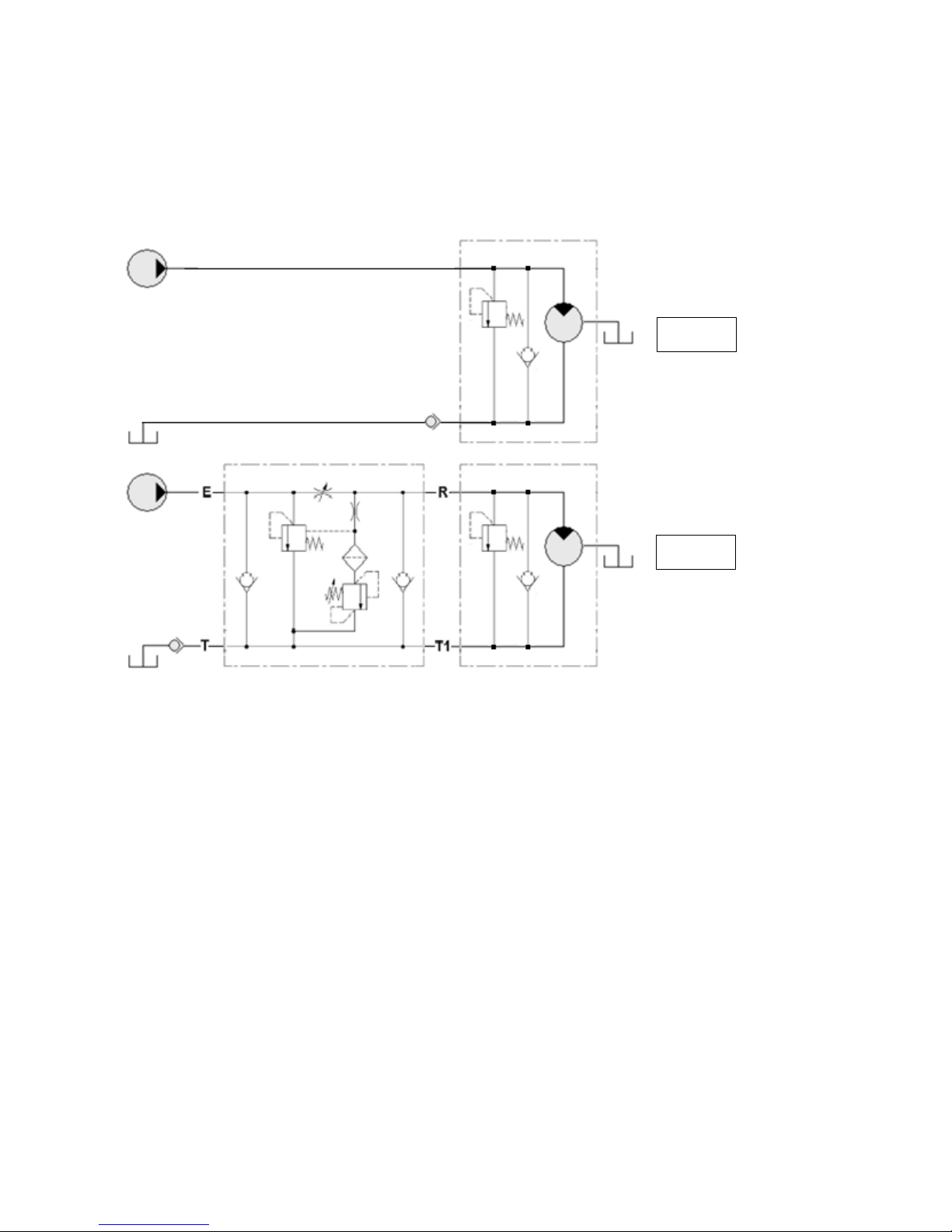
HYDRAULIK DIAGRAM ........................................................................................................................................................... 17
OIL SUPPLY ......................................................................................................................................................................... 17
REGULAR MAINTENANCE TASKS.............................................................................................................................................. 18
REGRINDING ....................................................................................................................................................................... 18
TENSIONING THE BELTS ......................................................................................................................................................... 19
BELT DIAGRAM .................................................................................................................................................................... 19
TECHNICAL DATA AND DESCRIPTION OF WORKING TOOL ........................................................................................... 20
SAFETY ......................................................................................................................................................................... 21
POTENTIAL DANGERS ASSOCIATED WITH THE USE OF THIS MACHINE ............................................................................................... 21
BEFORE USING THIS MACHINE ................................................................................................................................................. 22
Always: ....................................................................................................................................................................... 22
Never: ......................................................................................................................................................................... 23
ADDITIONAL SAFETY ADVICE .................................................................................................................................................. 24
Training ...................................................................................................................................................................... 24
Working in Public Places ............................................................................................................................................ 24
Warning Signs ............................................................................................................................................................ 24
Suggested Warning Signs Required ............................................................................................................................ 24
Use of Warning Signs ................................................................................................................................................. 24
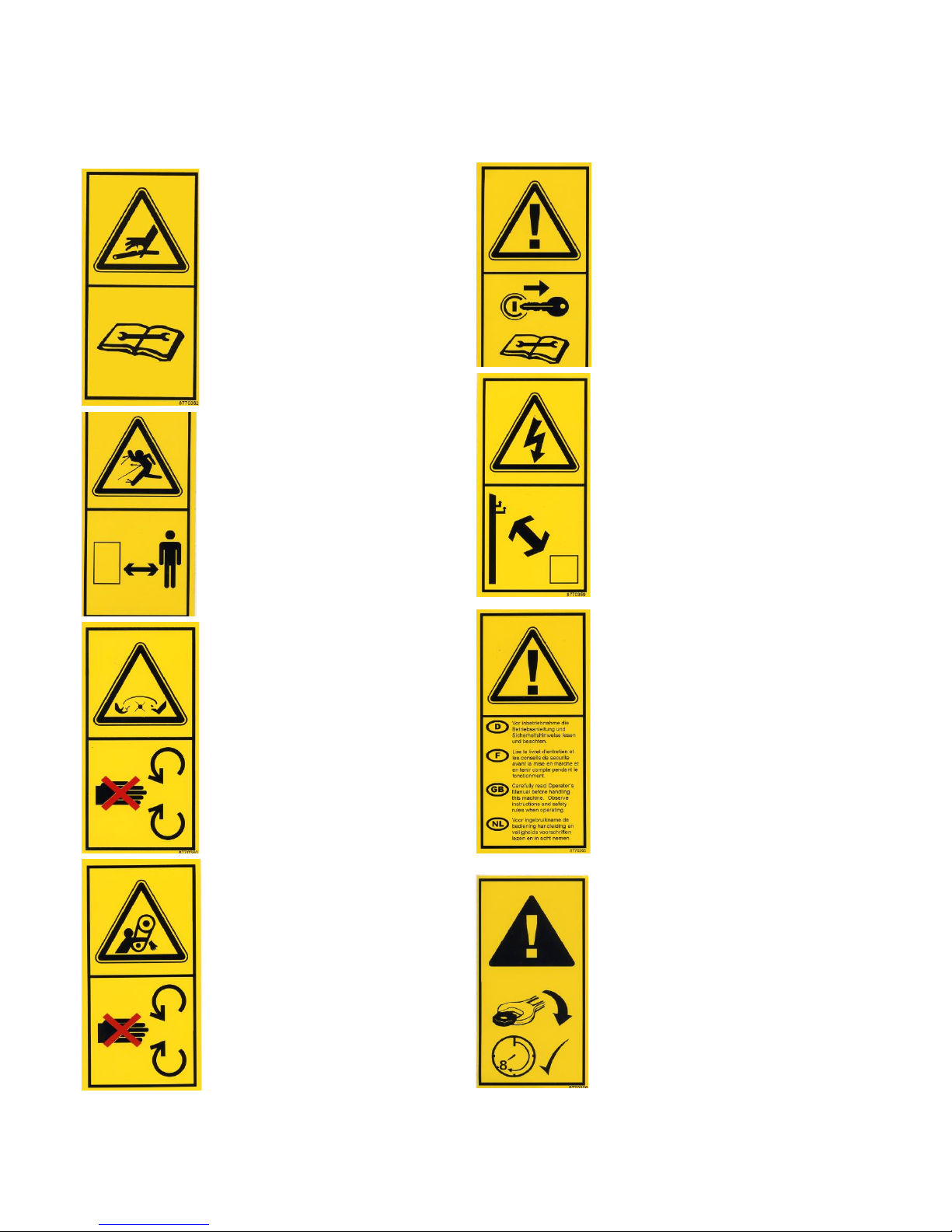
SAFETY STICKERS .................................................................................................................................................................. 25
STORAGE ..................................................................................................................................................................... 26
NOISE MEASURING ...................................................................................................................................................... 26
SUPLIERINFORMATION AND CE-DECLARATIONS ......................................................................................................... 26
WARNINGS, BAN AND DIRECTIONS ............................................................................................................................. 27
DISASSEMBLE .............................................................................................................................................................. 27
Page 5

Side 5 af 27
Introduction
Dear customer!
Your new Greentec machine is constructed with background in more than 20 years experience with tractor
mounted machines to maintenance of green areas. This machine is produced by the latest technology and
recognized safety regulations, standards and regulations.
We want to make a product available in such a way, that neither the use of the machine during transportation
or maintenance of the machine causes any damage or misunderstandings.
This parts list contains information that are important and useful for maintaining your Greentec machine's reliability, dependability and value.
You are welcome to visit our website www.greentec.eu - where the login via the dealer's access gives you the
latest updates on instructional and part books on our entire product range. The password for dealer log-in:
PUBLISHER
We hope, you will be pleased with your new Greentec machine.
Best regards,
John Christensen
Sales Director Greentec A/S
Greentec’s vision is to develop and sell quality machines for the maintenance of green areas, including in
agriculture, in industry, at airports and in the local sector. Through innovative product development, we will
strive to become a leader in our field.
All machines are developed in a simple and functional design in close cooperation with dealers and end users.
It is our goal to cover every need in the market segment with preferably 2 different solutions. In-depth analysis
of requirements and serious advice to the customer is offered the best solution, where individual needs can be
met through the modularity of the product program.
Our goal is also to offer the best possible after sales service, and a quick and efficient spare parts supply.
Page 6

Side 6 af 27
Important
Please ensure that this manual is handed to the operator before using the machine for the first time.
The operator must fully understand the contents of this manual before using this machine.
(If the machine is resold the Manual must be given to the new owner.)
Please, fill out the following information. It is practical information that is useable when ordering
spare parts.
Serielnumber: ……………………………………………………
Delivery date: ……………………………………………………
Dealer name: ……………………………………………………
Address: ……………………………………………………
……………………………………………………
Tel. / Fax No.: ……………………………………………………
Greentec A/S
Merkurvej 25
Dk-6000 Kolding
Tel: +45 7555 3644
Fax: +45 7555 4243
E-mail: [email protected]
Http: www.greentec.eu
Page 7

Side 7 af 27
General Information
Read this manual before fitting or operating the machine or accessory. Whenever any doubt
exists contact your local dealer or the GreenTec Service Department for assistance.
Only use ‘Genuine GreenTec Parts’ on GreenTec machinery and equipment.
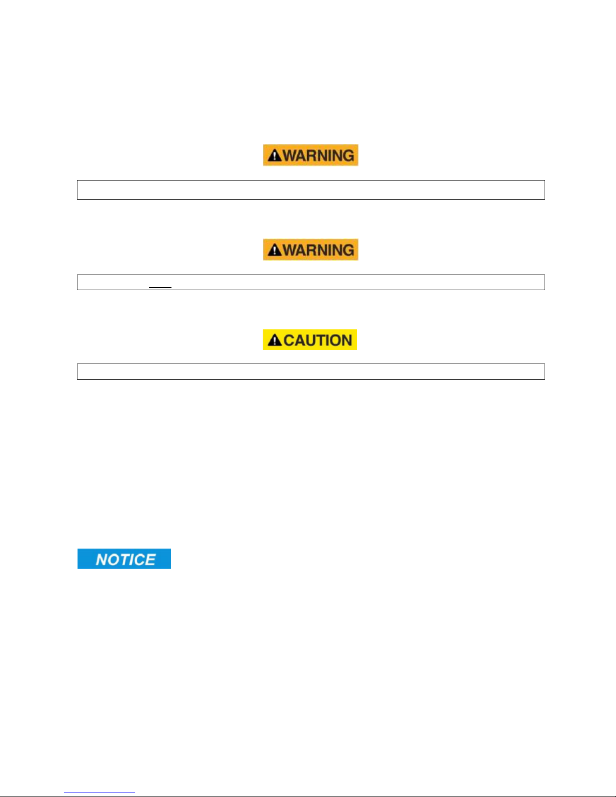
DEFINITIONS: The following definitions apply throughout this manual;
DANGER: Alerts to a hazardous situation which will result in death or serious injury if not
observed carefully.
WARNING: Alerts to a hazardous situation which could result in death or serious injury if not
observed carefully.
CAUTION: Alerts to a hazardous situation which could result in damage to the machine
and/or equipment if not observed carefully.
NOTICE: Specific or general information considered important or useful to emphasise.
LEFT HAND (LH) & RIGHT HAND (RH): These terms are applicable to the machine when
fitted to the tractor and viewed from the rear; these terms also apply to tractor references.
SERIAL PLATE
All machines are equipped with a serial number plate containing important information
relating to the machine including a unique serial number used for identification purposes.
Note: Images in this manual are provided for instruction and informational purposes only and may
not show components in their entirety. In certain instances images may appear different to the actual
machine; where this occurs the general procedure will be basically the same.
Page 8

Side 8 af 27
Merkurvej 25, DK-6000 Kolding, Denmark
CE Declaration of Conformity
Adapted EEC directive
2006/42/EC, 89/392/EEC & 98/37/EC
We, GreenTec A/S, Merkurvej 25, 6000 Kolding, hereby declare that in terms of its design, method
of construction and our execution thereof, the item of machinery described below complies with the
basic health and safety regulations of the respective EU Directives. The Machinery Directive is supported by the following harmonized standards:
DS/EN ISO 12100 3rd edition 2011. Safety of Machinery – General principles for design –
Risk assessment and risk reduction.
DS/EN 953+A1 4th edition 2010. Safety of Machinery – Guards-General requirements for the
design and construction of fixed and movable guards.
DS/EN ISO 4413 1th edition 2010. Hydraulic fluid power – General rules and safety require-
ments for systems and their components.
Product: Quadsaw LRS 2001
Product code: 9992001L
Serial no: 214824671
Type: Quadsaw
The EC Declaration only applies if the machine stated above is used in accordance with the
operating instructions.
on behalf of
Date: 26.09.2014 Signature:________ _________________________
John Christensen Sales Director
Page 9
Side 9 af 27
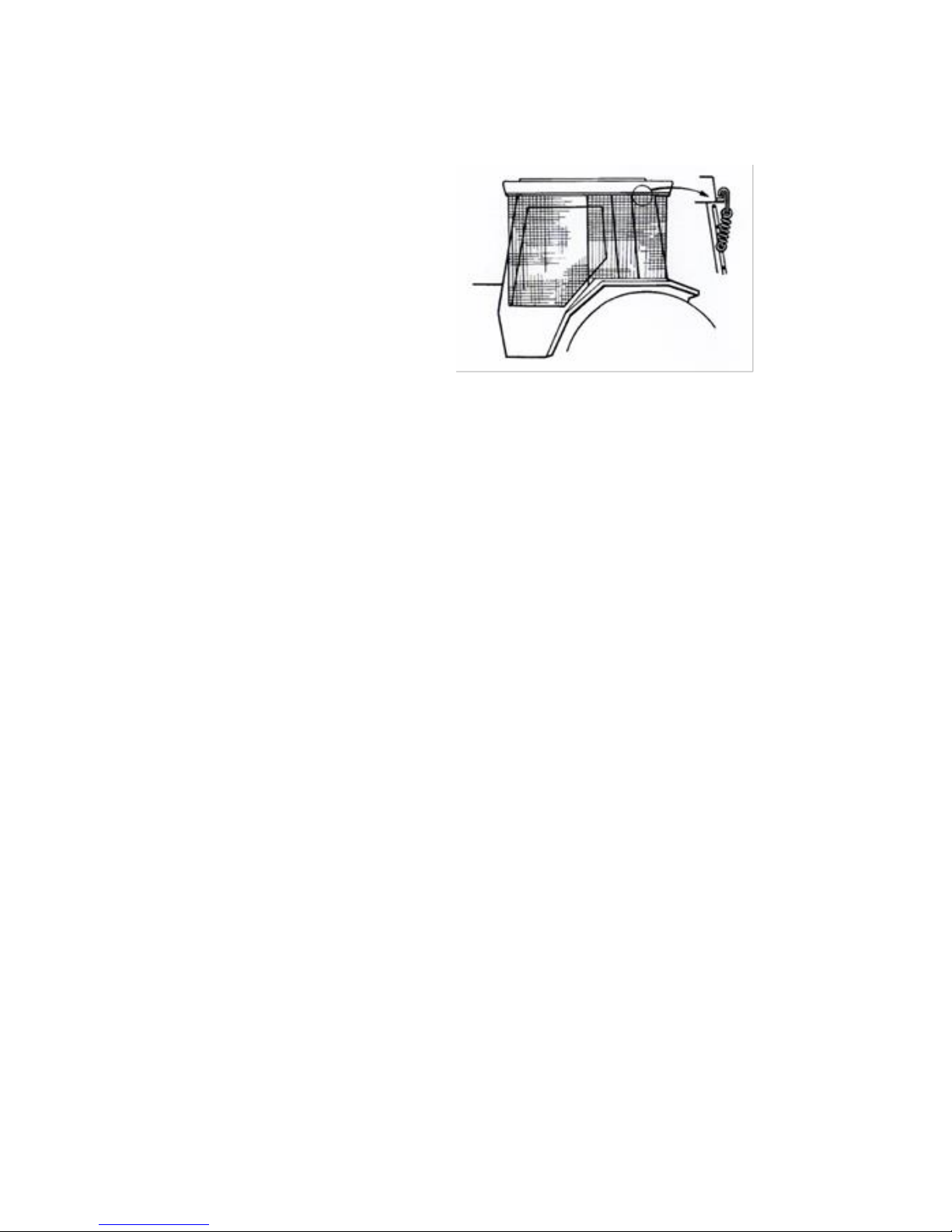
VEHICLE / TRACTOR PREPARATION
We recommend vehicles are fitted with cabs
using ‘safety glass’ windows and protective
guarding when used with our machines.
Fit Operator Guard (See drawing) using
the hooks provided. Shape the mesh to cover
all vulnerable areas. The driver must be
looking through mesh and/or polycarbonate
glazing when viewing the working tool in any
working position - unless the vehicle/ cab
manufacturer can demonstrate that the penetration resistance is equivalent to, or higher
than, that provided by mesh/polycarbonate glazing. If the tractor has a roll bar only, a frame
must be made to carry both mesh and polycarbonate glazing. The operator should also use
personal protective equipment to reduce the risk of serious injury such as; eye protection
(mesh visor to EN1731 or safety glasses to EN166), hearing protection to EN352, safety
helmet to EN297, gloves and high visibility clothing.
Vehicle Ballast
It is imperative when attaching ‘third-party’ equipment to a vehicle that the
maximum possible stability of the machine and vehicle combination is achieved – this can be
accomplished by the utilisation of ‘ballast’ in order to counter-balance the additional
equipment added.
Front weights
May be required for rear mounted machines to place 15% of total outfit
weight on the front axle for stable transport on the road and to reduce ‘crabbing’ due to the
drag of the cutting unit when working on the ground.
Rear weights
May be required to maintain a reasonable amount of rear axle load on the
opposite wheel from the arms when in work; for normal off-ground work i.e. hedge cutting
this should be 20% of rear axle weight or more for adequate control, and for ground work i.e.
verge mowing with experienced operators, this can be reduced to 10%.
All factors must be addressed in order to match the type and nature of the equipment added
to the circumstances under which it will be used – in the instance of Power Arm hedgecutters
it must be remembered that the machines centre of gravity during work will be constantly
moving and will differ from that during transport mode, therefore balance becomes critical.
Page 10

Side 10 af 27
Factors that affect stability
Centre of gravity of the tractor/machine combination.
Geometric conditions, e.g. position of the cutting head and ballast.
Weight, track width and wheelbase of the tractor.
Acceleration, braking, turning and the relative position of the cutting head during these
operations.
Ground conditions, e.g. slope, grip, load capability of the soil/surface.
Rigidity of implement mounting.
Suggestions to increase stability
Increasing rear wheel track; a vehicle with a wider wheel track is more stable.
Ballasting the wheel; it is preferable to use external weights but liquid can be added to
around 75% of the tyre volume – water with anti-freeze or the heavier Calcium Chloride alternative can be used.
Addition of weights – care should be taken in selecting the location of the weights to
ensure they are added to a position that offers the greatest advantage.
Front axle locking (check with tractor manufacturer).
NOTE: The advice above is offered as a guide for stability only and is not a guide to vehicle strength. It is recommended that you consult your vehicle manufacturer or local dealer to obtain specific advice on this subject, additionally advice should be sought from a tyre specialist with regard to tyre pressures and ratings suitable for the
type and nature of the machine you intend to fit.
Page 11
Side 11 af 27
Mounting the Quadsaw
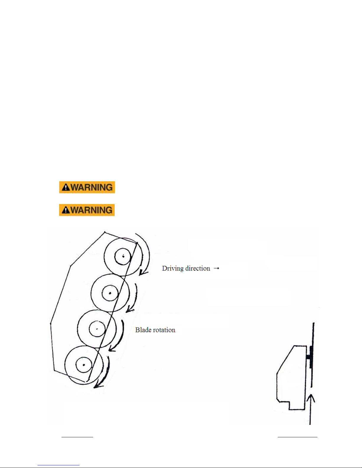
The blades MUST be mounted in a downward cut rotation. Mount the blades so they are cutting
down (Must run same way as the tractor) (Fig. 1).
Mount the Quadsaw so the blades are running in the driving direction (Fig. 2).
Mount the hydraulic hoses so the blades are running in correct direction. Separate drainage hose
(max 1,5 bar) must be led directly to the oil reservoir.
Also separate, the Return hose must be led directly to the oil reservoir (max 15 bar)
Check for oil leak.
First time the machine is used. Measure the blade rpm. LRS 2001 and 2401 (3000 – 3200 rpm).
Holding this speed is important for the best optimum performance.
Never use the machine with broken or missing sawblades.
Blades must be mounted in a downward cutting rotation only.
Fig. 1 Blade rotation Fig. 2 Driving direction
Page 12
Side 12 af 27
Attachment of the machine must be performed in a safe location on a firm level site.
Care should be adopted at all times when handling or manoeuvring the machine during the
attachment procedure; ensure all persons remain clear of the cutting blades which possess the
potential to cause injury even when stationary. For reasons of safety the blade guard should be
fitted to machine at all times and only removed for machine operation.
Never use the machine on a vehicle that is unstable or unsuitable.
Attachment to Armsystem or Mounting Carrige
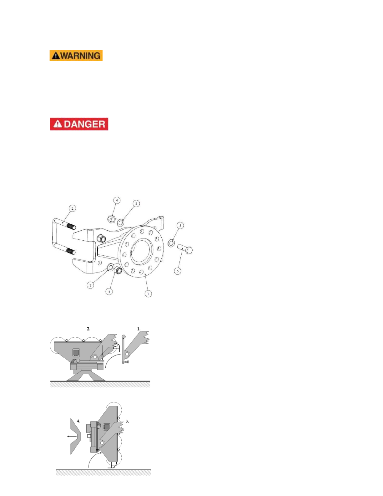
Can be attached to Arm-system with a clamp bracket. Nuts should be torqued 200 Nm.
Spearhead Twiga & GreenTec HXF 2802, 3300 & 3302 are all specially designed to carry the Quadsaw.
The HXF is a mounting carriage designed for attaching Quadsaws to Tractor loaders and Tele-
handlers. features a reach of approximately 2,0-
2.5 metres, 180° manual folding system, and
hydraulic collision safety. The overall weight of
the unit, without tools, is 180-225kg. If necessary, suitable ballasting should be fitted to the
vehicle to ensure the unit remains stable and
balanced in all working positions under all conditions.
The Spearhead Twiga system features a reach of
approximately 4,5-9,0 metres, hydraulic folding
system, and hydraulic collision safety. The overall weight of the unit, without tools, is 1100-
1750 kg. If necessary, suitable ballasting should
be fitted to the vehicle to ensure the unit remains stable and balanced in all working positions under
all conditions.
1. Drive up to the machine, tilt attach
ment bracket into the horizontal
position.
2. Locate attachment bar into hooks
and secure latches.
3. Tilt bracket backwards 900.
4. Detach supporting legs (only some
models)
Page 13
Side 13 af 27
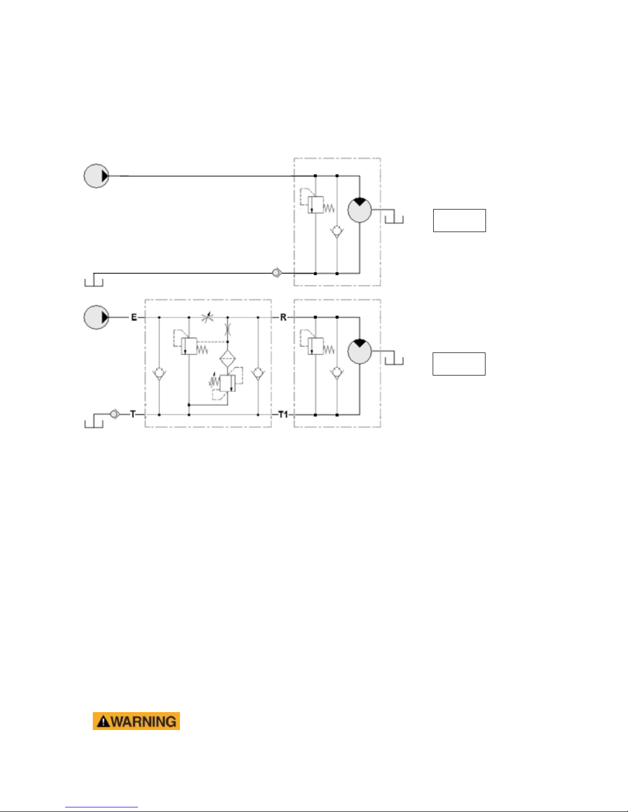
Hydraulik diagram
Fig 1. Standard
Fig. 2 Med mængdedeler
Operation / Introduction
The Quadsaw is used for cutting branches and trees up to a max. diameter of (LRS 2001 120 mm).
(LRS 2401 160 mm). Branches thicker than (LRS 2001 80 mm) (LRS 2401 120 mm) must be cut one
of the time.
Vertical cutting is allowed up to a 45 degree angle. Horizontal cutting is possible on hedges with a
width up to 1.2 m and a branch diameter up to 40 mm. thicker branches might stop the blades and get
stuck in the machine.
It is recommended that forward speed is kept to a minimum when starting work in order to retain the
correct working speed of the blades. Set the angle of the Quadsaw so it is positioned at right angles to
the work and adjust the machine position so the branches meet the saw blades ‘straight on’.
Wherever possible try to keep the blades running vertical in relation to the direction of travel,
this will help prevent them from ‘distorting’ during operations.
Should small branches, debris or unwanted material get stuck in the blades the machine and tractor
must be switched off and the starting key removed before attempting to clear the blockage. If necessary, remove the belt cover to gain better access to the blockage; replace cover immediately before
starting or using the machine.
Never run the machine without beltcover mounted.
Fig. 1
Fig. 2
Page 14

Side 14 af 27
Great care must taken when attempting to clear debris from the blade
and/or belt area of the machine; sharp components and numerous pinch
risk points exist in these locations. Safety gloves and safety eyewear
should be worn and wherever possible the use a suitable tool should be
used to remove any debris to ensure hands and fingers are kept clear of
any risk areas.
Never use the machine as a stationary saw for making firewood.
Never use the machine as a crane.
When in charge of the machine always obey the following rules;
Always inspect the work area prior to operation and remove any dangerous materials.
Never operate the machine with persons or animals in close proximity.
Ensure all cab guarding is in place and the tractor windows are kept shut.
Only operate the machine at the correct blade speed.
Never transport the machine without the blade protection guards fitted.
Never approach the machine when it is running, always switch it off and stop the tractor.
Always remove the vehicle ignition key before leaving the cab.
Never use the machine to perform tasks it was not designed for.
Always lower the machine to rest on the ground with blade protection guards fitted when
the unit is parked up or not in use.
Page 15

Side 15 af 27
Driving recommendations
It is recommended to travel at a slow forward speed when starting work in order to obtain and keep
the recommended rpm of the blades. Adjust the angle of the saw to approx 90 degrees in relation to
the branches. If a thick branch is approaching the branch reflectors, the working height must be adjusted for the branch to hit the saw blades straight on.
If small branches or other unwanted material get stuck in the blades, the machine must be stopped
and cleaned.
Always ensure that the blades are running vertical related to the direction of the travel. This will prevent the blades from bending too much.
It might be an advantage to mount a skid at the bottom of the Quadsaw to prevent the saw blades from hitting the ground. (Optional equipment)
The cutting angle is as std. a “top-link”, and can only be adjusted when the machine is stopped.
A hydraulically ram (option), can be mounted. Operate the ram in the required
direction to set the desired cutting angle before starting work. The ram may be
operated during work to make minor angling adjustments, but it is recommended to stop work before
making major adjustments to the cutting angle.
To prevent sawblades in blocking there is mounted a Branchcarrier part no.
200112.0, a Plastic-strip part no. 200110.0 in the full length of the machine
and wearplates part no. 200153.0 under each sawblade to prevent sawblades bending. If the sawblades anyway blocks, then stop the saw, stop the carrier, take out the ignitionkey, pull the handbrake, take your safety goggles and gloves on and remove the jammed piece of wood.
Page 16

Side 16 af 27
Maintenance
Beware of blades and belt areas when maintaining and servicing.
After 2 hours work all Taper-lock must be retightened to 31 Nm.
After 10 hours work all bolts, screws and Taper-lock bushes must be retightened. If the bushes
loosen at a later time they may be secured with Locktite.
All bolts must be retightened on a regular basis.
Year 2001-2011: The plastic strips are adjusted down to 1 mm clearance from the blades. The
plastic strips must be replaced if this exceeds 5 mm. The branch deflectors must be adjusted as
close as possible to the blades without touching.
Year 2011 and forward: The plastic strip on LRS 2401should be in line to the body.
Dismount the belt guard to clean the housing.
Inspect and if necessary adjust the belts. (See belt diagram here or under belt guard).
GreenTec A/S recommend changing all sawblade-axles after 1500 hours of work, because of the
possibility of metal fatigue.
After inspection or service ALL protection plates and guards must be replaced.
GreenTec A/S recommend changing all sawblade-axles after 1500 hours of
work, because of the possibility of metal fatigue.
Lubrication
Grease the lubrication points on machine on the following basis;
Daily prior to use.
Always prior to storage.
Always after it has been washed.
Never use grease that contains Molybdenum Disulfide on nylon bushes.
Hydraulic Hoses
Inspect hydraulic hoses and fittings on a daily basis prior to using the machine; ensure they
are free from damage or leaks and that the hoses are not rubbing on machine components.
Any damaged hoses or fittings should be repaired or replaced immediately.
Run new hoses alongside the old ones prior to removal to ensure the correct routing is
retained. When replacing a hose avoid twisting it, use 2 spanners to tighten it.
Ensure hoses bend with machine movements and that they do not twist or strain.
All hose connections are of a ‘soft seal’ type and should only be turned a further 1/2 turn
more than hand tight in order to be leak-proof (see table below).
BSP (size)
Nm
1/4”
24 Nm
3/8”
33 Nm
1/2”
44 Nm
3/4”
84 Nm
1”
115 Nm
Page 17
Side 17 af 27
Hydraulik diagram
Fig 1. Standard
Fig. 2 Med mængdedeler
Oil Supply
Check oil level in the tank each day prior to starting work - it is good practice to constantly
keep an eye on the sight glass level as a ruptured pipeline can empty a system within
minutes; a pump or motor that runs out of oil will be damaged beyond repair very quickly.
The oil must be changed if there are signs that it is contaminated (discolored).
Ensure cleanliness when replacing or topping up the oil by;
Carefully cleaning around the filler neck prior to opening.
Always using clean containers for refilling the system.
Regular inspection of the filtration system.
Never letting the oil level fall below the level in the sight glass.
Check daily for all hydraulic connections and fittings are in good condition. Any defect or leak
must be immediately repaired, it is part of the daily maintenance that will reduce costs and
prolong machine life.
If fittings require retightening always use 2 spanners and avoid over tightening. If the fitting
continues to leak, replace it.
Fig. 1
Fig. 2
Page 18
Side 18 af 27
Regular Maintenance Tasks
After every 4 hours of use the following maintenance task should be observed;
Check bolts for tightness and – retighten if required.
Check valve block, hoses and fittings for signs of leaks – retighten or replace seals if
required.
Bolts and bushes should be greased and retightened.
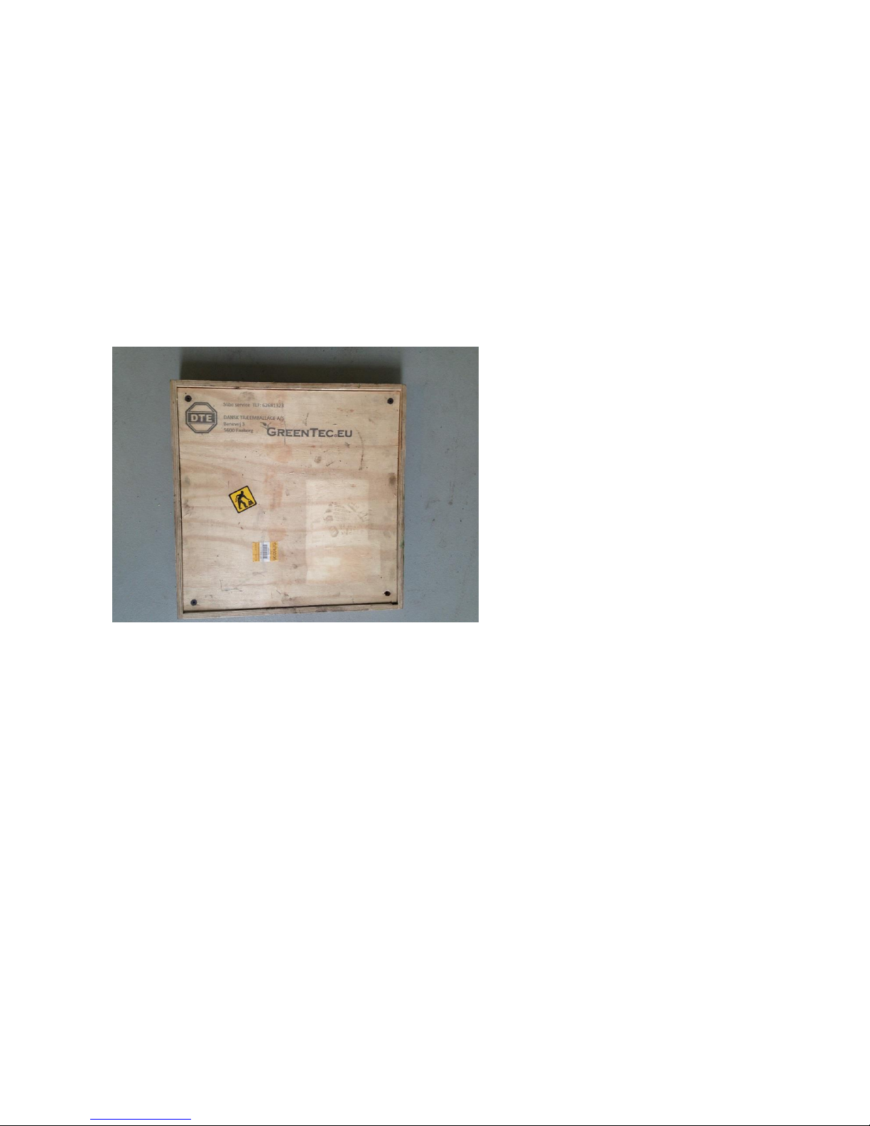
Regrinding
If sawblades are send to regrinding, GreenTec offers a wooden box made for that purpose. can contain four sawblades.
Page 19
Side 19 af 27
Tensioning the Belts
Great care must be adopted when servicing the machine as there is
risk of trapping hands or fingers in the belts, pulleys or sawblades.
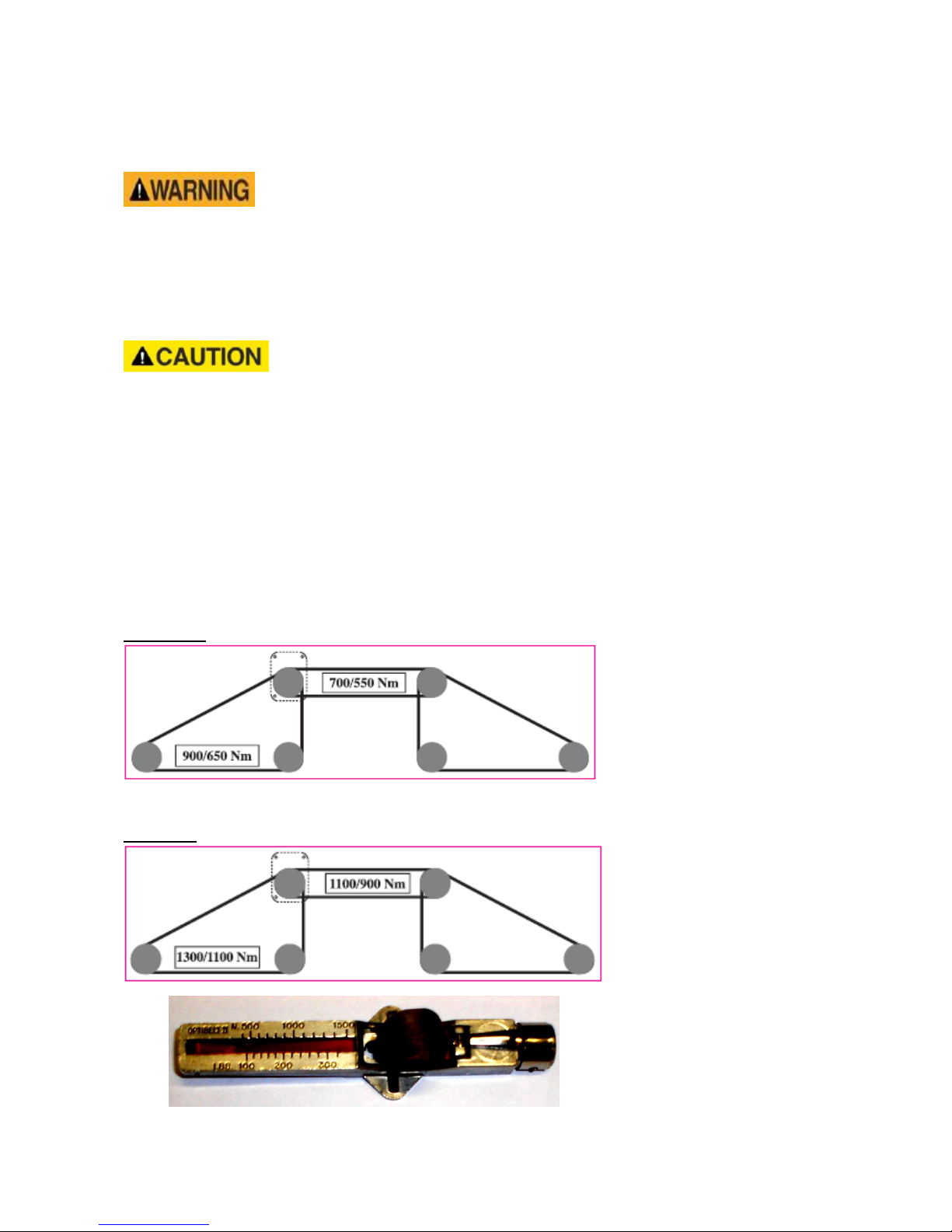
It is utmost importance that the belts are correctly mounted and tightened. When new belts are
mounted they must be tensioned to (LRS 2001 700 Nm) (LRS 2401 1100 Nm) for the short and (LRS
2001 900 Nm) (LRS 2401 1300 Nm) for the long belts.
After 3-5 working hours the belts may have slackened and must be checked.
The tension has now changed to (LRS 2001 550 Nm) (LRS 2401 900 Nm) for
the short and (LRS 2001 650 Nm) (LRS 2401 1100 Nm) for the long belts.
Take the lid off.
Check the Nm setting with tool 200155.0
Adjust powerbelts if required.
Re-check again with tool 200155.0
Remount the lid.
Contact GreenTec A/S After Sales Department if you have any questions. We might help you with a
piece of good advice.
Belt diagram
LRS 2001
LRS 2401
Tool for belt tension control
Part no. 200155.0
Page 20

Side 20 af 27
Technical data and description of working tool
Quadsaw for mounting on hydraulic hedge cutters.
Frame with 4 shafts.
500 mm or 590 mm saw blades. Depending on model.
Each shaft is driven by vee belts, and the whole unit is powered by a hydraulic motor.
Branch deflectors are placed between the blades.
The Quadsaw is supplied with a special bracket enabling mounting on various vehicles / carriers.
Model
Lrs 2001
Lrs 2401
Working width
2000 mm
2380 mm
Blade speed
3000 – 3200 rpm.
3000 – 3200 rpm.
Blade diameter
500 mm
590 mm
Teeth per blade
72 teeth.
78 teeth.
Material
Hardened steel with special teeth
HM precision blade
Hardened steel with special teeth
HM precision blade
Performance
1 – 120 mm branch diameter
1 - 160 mm branch diameter
Application
Vertical
Vertical
Oil flow 15,0 CC
50 Litres. Relief valve 180 bar
50 litres. Relief valve 180 bar
Oil flow 28,0 CC
85 Litres. Relief valve 150 bar
85 litres. Relief valve 150 bar
e. g. Twiga 4-7000
PTO speed 540
PTO speed 540
e. g. Twiga MID
PTO speed 540
PTO speed 540
e. g. Twiga PRO HP
PTO speed 440
PTO speed 440
Driving
1-5 km/h
1-5 km/h
Page 21

Side 21 af 27
Safety
This machine has the potential to be extremely dangerous - in the wrong hands it can
kill or maim; it is therefore imperative that both owner and operator of the machine
reads and understands the following section to ensure they are fully aware of the
dangers that do, or may exist, and their responsibilities surrounding the use and
operation of the machine. The operator of this machine is responsible not only for
their own safety but equally for the safety of others who may come into the close
proximity of the machine, as the owner you are responsible for both.
All operators must be fully competent in the use of this machine and also the machine
to which it is attached and must read and understand the operation manuals for both
machines before attempting to attach or operate this equipment.
When the machine is not in use it should be lowered to rest on the ground. In the
event of any fault being detected with the machine’s operation it must be stopped
immediately and not used again until the fault has been corrected by a qualified
technician.
Potential Dangers associated with the use of this machine
▲ Being hit by debris thrown by rotating components.
▲ Being hit by machine parts ejected through damage during use.
▲ Being caught on a rotating power take-off (PTO) shaft.
▲ Being caught in other moving parts i.e.: belts, pulleys and cutting heads.
▲ Electrocution from Overhead Power Lines (by contact with or ‘flashover’ from).
▲ Being hit by cutting heads or machine arms as they move.
▲ Becoming trapped between tractor and machine when hitching or unhitching.
▲ Tractor overbalancing when machine arm is extended.
▲ Injection of high-pressure oil from hydraulic hoses or couplings.
▲ Machine overbalancing when freestanding (out of use).
▲ Road traffic accidents due to collision or debris on the road.
Page 22

Side 22 af 27
Before using this machine
Always:
Ensure the operator has read this handbook and has been trained to use the machine.
Ensure that the tractor meets the minimum weight recommendations of the machine manufac-
turer and that ballast is used if necessary.
Ensure all cab safety guards are in place and all tractor windows are closed. Newer allow an
inexperienced person to operate the machine without supervision. If tractor is without cabin
then mount metal mesh or polycarbonate guards of suitable size and strength to protect the operator against thrown debris or parts
Wear ear defenders if operating without a quiet cab or with the cab windows open.
Inspect work area for wire, steel posts, large stones and other dangerous materials. If such items
are found, remove them.
Work at a safe speed, taking into account terrain, passing vehicles and obstacles.
Never start or continue to work a machine if people are nearby or approaching - Stop and
wait until they are at a safe distance before continuing. WARNING: Some cutting heads
may continue to ‘freewheel’ for up to 20 seconds or more after being stopped.
Remove the ignition key, before leaving the cab.
Ensure that the saw or flail head is firmly on the ground, no weight is on the tractors hydraulics
and blades / knifes have stopped spinning, before leaving the tractor cab
Check that all safetyguards are properly fitted, check there are no damaged or loose parts.
Beware of the danger of overhead power cables. The operator must be aware of the maximum
height and reach of the machine when working under power cables. The minimum legal height
for 11,000 and 22,000-volt cables is 5.2 metres from the ground. When fully extended, the machine may well exceed this height so extreme caution should be practised. For more information contact the Health and Safety Executive or your local power company.
Operate the blades at a speed between 3000-3200 rpm (depending on model).
Ensure that all warning labels are always visible and that they are not damaged, defaced or
missing.
Follow the manufacturer’s instructions for attachment and removal of machine from the tractor.
Page 23

Side 23 af 27
Never:
Operate the machine until you have read and understood the relevant Handbook and are famil-
iar with the controls.
Operate the machine with other people present, as it is possible for debris to be thrown from the
saw blades in all directions.
Use a machine that is poorly maintained or has guards that are damaged or missing.
Allow an inexperienced person to operate the machine without supervision.
Use or fit a machine onto a tractor if it doesn’t meet the manufacturer’s specification.
Allow children to play on or around the machine at any time.
Attempt any maintenance or adjustment without first disengaging the pto/hydraulicpump, low-
ering the head to the ground, stopping the tractor engine and applying the tractor parking brake.
Stop the engine with the power take-off (PTO) engaged.
Transport with the power take-off (PTO) engaged.
Exceed maximum oil pressure of 250 bar in the hydraulic hoses.
Use a machine if the hydraulic system shows signs of damage.
Attempt to detect a hydraulic leak with your hand, use a piece of card.
Operate the tractor or any controls from any position other than from the driving seat.
Transport without the blade protection guards mounted.
Operate with sawblades/flails missing.
Operate with wire around the rotor/sawblade. Stop immediately.
Use the head at an angle, which may throw debris towards the cab.
Leave the cab without removing the ignition key.
Attempt to use the machine for any purpose other than that it was designed for.
Attempt any maintenance or adjustment without first disengaging the PTO, lowering the head
to the ground, stopping the tractor engine and applying the tractor parking brake.
Enter the working area of the machine (risk of injury!).
Page 24

Side 24 af 27
Additional Safety Advice
Training
Operators need to be competent and fully capable of operating this machine in a safe and efficient
way prior to attempting to use it in any public place. We advise therefore that the prospective operator make use of relevant training courses available such as those run by the Agricultural Training
Board, Agricultural Colleges, Dealers and GreenTec.
Working in Public Places
When working in public places such as roadsides, consideration should be paid to others in the vicinity. Stop the machine immediately when pedestrians, cyclists and horse riders etc. pass. Restart only
when they are at a distance that causes no risk to their safety.
Warning Signs
It is advisable that any working area be covered by suitable warning signs and statutory in public
places. Signs should be highly visible and well placed in order to give clear advanced warning of the
hazard. Contact the Department of Transport or your Local Highways Authority to obtain detailed
information on this subject. The latter should be contacted prior to working on the public highway
advising them of the time and location of the intended work asking what is required by way of signs
and procedure. – ‘Non-authorised placement of road signs may create offences under the Highways Act’.
Suggested Warning Signs Required
‘Road works ahead’ warning sign with a supplementary ‘Hedge cutting’ plate. ‘For 1 km’ or ap-
propriate shorter distance may be added to the plate.‘Road narrows’ warning signs with supplementary ‘Single file traffic’ plate. White on blue ‘Keep left’ (*) arrow sign on rear of machine.
* Note – this applies to EU Market machines where traffic passes to the left of a machine working in the same direction as the traffic flow. The direction, use and colour of the arrow sign will depend on the country of use and the Local
Highway Authorities regulations in the locality.
Use of Warning Signs
▲ On two-way roads one set of signs is needed facing traffic in each direction.
▲ Work should be within 1 km of the signs.
▲ Work only when visibility is good and at times of low risk e.g.: NOT during ‘rush-hour’.
▲ Vehicles should have an amber-flashing beacon.
▲ Ideally, vehicles should be conspicuously coloured.
▲ Debris should be removed from the road and path as soon as practicable, and at regular inter-
vals, wearing high visibility clothing and before removing the hazard warning signs.
▲ Collect all road signs promptly when the job is completed.
Safety Gear: It is recommended that the following personal protective equipment is worn when operating and/or maintaining this machine; Coveralls, safety boots, safety glasses, hearing protection,
safety helmet, protective gloves.
Although the information stated here covers a wide range of safety subjects it is impossible to predict every eventuality that can occur under differing circumstances whilst operating this machine.
No advice given here can replace ‘good common sense’ and ‘total awareness’ at all times, but will
go a long way towards the safe use of your GreenTec machine.
Page 25
Side 25 af 27
Safety Stickers
Warning
Danger – flying objects.
Keep safe distance from
the machine as long as
the engine is running.
Warning
Stop engine and remove
key before performing
maintenance or repair work.
Warning
Avoid fluid escaping under pressure. Consult
technical manual for service procedures.
Warning
Carefully read operator’s
manual before handling this
machine. Observe instructions and safety rules when
operating.
Warning
Stay clear of rotating
sawblades / knifes.
Warning
Do not remove / open
guard when parts are rotating.
Warning
Beware of overhead electrical power lines.
Warning
Check all nuts and
bolts are tight every
8 hours – retighten if
required.
Page 26

Side 26 af 27
Storage
Before storing away, thoroughly wash the machine, removing all traces of grass and dirt.
Great care must be taken when washing with high-pressure hoses, do not hold
the water jet close to the paintwork. Use steam cleaners with caution, be sure
to remove all detergents to avoid any discolouring or damage to paint. Grease all grease points until
fresh grease shows. Slacken rotor drive belts (where fitted).
It is important where possible to store undercover to protect against rain and sunlight. Always ensure
a firm level surface.
Smear grease on all areas vulnerable to corrosion, in particular the chrome on
the ramrods.
Remember: regular maintenance will greatly increase the life of the machine.
Noise measuring
Noise measuring has been made on the machine during normal working conditions at GreenTec A/S,
Denmark, with a Delta OHM Noise measurer, type HD 8701.
The energy A-weighted Sound pressure is lower than: 90 dB (A).
The test has been done in a distance of 1 meter from the machines critical noise maker and in a height
of 1,5 m over the ground.
Suplierinformation and CE-declarations
Company name : GreenTec A/S
Address : Merkurvej 25
Mail code /City : DK-6000 Kolding
Country : Denmark
Tlf : +45 75 55 36 44
Telefax : +45 75 55 42 43
CE-declaration
Producent : GreenTec A/S
Tlf : +45 75 55 36 44
Telefax : +45 75 55 42 43
Machine No. : Lrs 2001 Lrs 2401
Delivery date : _____________
Delivery year : 2015
Page 27
Side 27 af 27
Warnings, ban and directions
Never attempt any maintenance or adjustment without first disengaging the pto/hydraulicpump.
Only authorised personal must do maintenance work on the equipment.
Read this manual carefully before using the machine.
Disassemble
Machine disengaged from all connections.
To ensure the most environmentally friendly removal, the machine must be
disassembled and the parts separated as following:
Category Example of parts
Rubber and plastic Hoses, plastic strip
Technical components Pumps, motors, hydraulic hoses
Pure metal Plates, pipes, guard
Removal of the parts must be done according to national and EU legislation.
 Loading...