

GREENSTAR 12Ri ErP, 15Ri ErP, 18Ri ErP, 24Ri ErP Installation, Commissioning And Servicing Instructions
Page 1
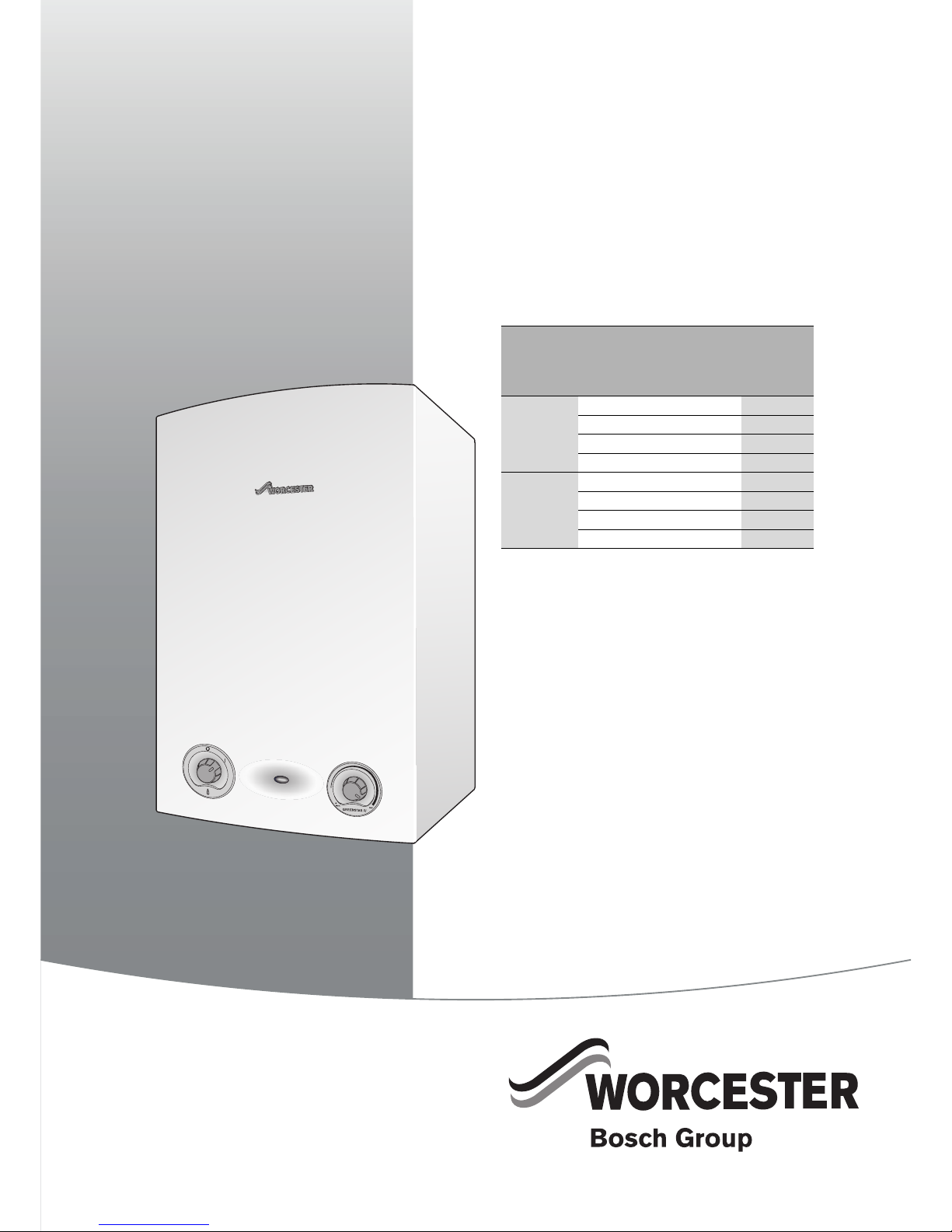
INSTALLATION, COMMISSIONING AND SERVICING INSTRUCTIONS
WALL HUNG RSF GAS FIRED CONDENSING BOILER
Greenstar Ri
ErP
6720644744-00.1Wo
FOR OPEN VENTED & SEALED CENTRAL HEATING SYSTEMS & INDIRECT MAINS FED DOMESTIC HOT WATER
6 720 813 283 (2015/07)
If you smell gas:
▶ Well away from the building: call the National Gas Emergency
Service on 0800 111 999.
▶ L.P.G. boilers: Call the supplier’s number on the side of the gas tank.
These appliances are for use with:
Natural Gas or L.P.G.
(Cat. II 2H 3P type C13, C33 & C53)
Model GC Number
Natural Gas 12Ri
ErP
41-406-41
15Ri
ErP
41-406-43
18Ri
ErP
41-406-45
24Ri
ErP
41-406-47
LPG 12Ri
ErP
41-406-42
15Ri
ErP
41-406-44
18Ri
ErP
41-406-46
24Ri
ErP
41-406-48
Page 2

CONTENTS
Greenstar Ri
ErP
- 6 720 813 283 (2015/07)2
CONTENTS
1 KEY TO SYMBOLS AND SAFETY PRECAUTIONS . . . . . . . . . . . . 3
1.1 Key to symbols . . . . . . . . . . . . . . . . . . . . . . . . . . . . . . . . . 3
1.2 Safety precautions . . . . . . . . . . . . . . . . . . . . . . . . . . . . . . 4
2 Regulations . . . . . . . . . . . . . . . . . . . . . . . . . . . . . . . . . . . . . . . . . . 5
3 APPLIANCE INFORMATION . . . . . . . . . . . . . . . . . . . . . . . . . . . . . 6
3.1 Appliance . . . . . . . . . . . . . . . . . . . . . . . . . . . . . . . . . . . . . . 6
3.2 Technical data . . . . . . . . . . . . . . . . . . . . . . . . . . . . . . . . . . 7
3.3 Energy efficiency . . . . . . . . . . . . . . . . . . . . . . . . . . . . . . . . 8
3.4 Boiler main components . . . . . . . . . . . . . . . . . . . . . . . . 10
4 PRE-INSTALLATION . . . . . . . . . . . . . . . . . . . . . . . . . . . . . . . . . . 11
4.1 Cleaning primary systems . . . . . . . . . . . . . . . . . . . . . . . 11
4.2 Mains supply . . . . . . . . . . . . . . . . . . . . . . . . . . . . . . . . . 11
4.2.1 Electrical supply . . . . . . . . . . . . . . . . . . . . . . . . . . . . . . 11
4.2.2 Gas supply . . . . . . . . . . . . . . . . . . . . . . . . . . . . . . . . . . . 11
4.3 Water systems and pipe work . . . . . . . . . . . . . . . . . . . . 11
4.4 Condensate pipe work . . . . . . . . . . . . . . . . . . . . . . . . . 13
4.4.1 Internal connections . . . . . . . . . . . . . . . . . . . . . . . . . . . 13
4.4.2 External connections . . . . . . . . . . . . . . . . . . . . . . . . . . 14
4.5 PRESSURE RELIEF PIPE WORK . . . . . . . . . . . . . . . . . . 15
4.6 Boiler location and clearances . . . . . . . . . . . . . . . . . . . 15
4.6.1 Installation . . . . . . . . . . . . . . . . . . . . . . . . . . . . . . . . . . . 15
4.6.2 Servicing clearances -
Ventilated compartment . . . . . . . . . . . . . . . . . . . . . . . . 15
4.6.3 Compartments: . . . . . . . . . . . . . . . . . . . . . . . . . . . . . . . 16
4.6.4 Boiler clearances- Unventilated compartments . . . . . 16
4.6.5 Installation clearances - unventilated compartments . 16
4.6.6 Bathrooms . . . . . . . . . . . . . . . . . . . . . . . . . . . . . . . . . . . 16
4.7 Plumbing manifold . . . . . . . . . . . . . . . . . . . . . . . . . . . . 17
4.7.1 Connections . . . . . . . . . . . . . . . . . . . . . . . . . . . . . . . . . . 17
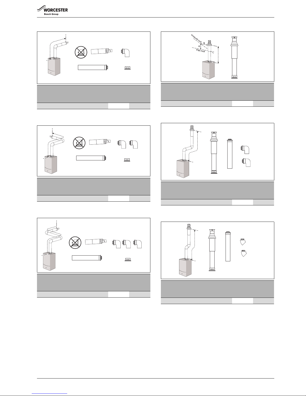
4.8 FLUE OPTIONS . . . . . . . . . . . . . . . . . . . . . . . . . . . . . . . 18
4.8.1 Flue lengths . . . . . . . . . . . . . . . . . . . . . . . . . . . . . . . . . . 18
4.9 Flue terminal positions . . . . . . . . . . . . . . . . . . . . . . . . . 20
4.10 Plume management terminal positions . . . . . . . . . . . . 21
4.10.1 Determine the plume management system length . . . 22
5 INSTALLATION . . . . . . . . . . . . . . . . . . . . . . . . . . . . . . . . . . . . . . 22
5.1 Unpacking the wall frame & ancillary items . . . . . . . . . 22
5.2 Wall mounting template & flue opening . . . . . . . . . . . . 23
5.3 Outer case removal . . . . . . . . . . . . . . . . . . . . . . . . . . . . 24
5.4 Boiler connection . . . . . . . . . . . . . . . . . . . . . . . . . . . . . 24
5.4.1 Condensate connection . . . . . . . . . . . . . . . . . . . . . . . . 25
5.5 Flue turret/adaptor installation . . . . . . . . . . . . . . . . . . 26
5.6 Electrical connections . . . . . . . . . . . . . . . . . . . . . . . . . . 27
6 COMMISSIONING . . . . . . . . . . . . . . . . . . . . . . . . . . . . . . . . . . . . 28
6.1 Pre-Commissioning checks . . . . . . . . . . . . . . . . . . . . . . 28
6.2 Filling the system . . . . . . . . . . . . . . . . . . . . . . . . . . . . . . 29
6.3 Water treatment . . . . . . . . . . . . . . . . . . . . . . . . . . . . . . . 29
6.4 Starting the appliance . . . . . . . . . . . . . . . . . . . . . . . . . . 29
6.5 Commissioning . . . . . . . . . . . . . . . . . . . . . . . . . . . . . . . . 30
6.5.1 Checking the gas inlet pressure . . . . . . . . . . . . . . . . . . . 30
6.5.2 Checking the gas rate . . . . . . . . . . . . . . . . . . . . . . . . . . . 31
6.6 CO and Combustion checks . . . . . . . . . . . . . . . . . . . . . . 31
6.7 Finishing commissioning . . . . . . . . . . . . . . . . . . . . . . . . 32
6.7.1 Replace the outer case: . . . . . . . . . . . . . . . . . . . . . . . . . 32
6.7.2 Install the bottom panel . . . . . . . . . . . . . . . . . . . . . . . . . 32
6.7.3 Hand over . . . . . . . . . . . . . . . . . . . . . . . . . . . . . . . . . . . . 32
6.7.4 Appliance guarantee . . . . . . . . . . . . . . . . . . . . . . . . . . . . 32
7 SERVICE AND SPARES . . . . . . . . . . . . . . . . . . . . . . . . . . . . . . . . 33
7.1 Inspection and service . . . . . . . . . . . . . . . . . . . . . . . . . . 33
7.2 Checking gas inlet pressure . . . . . . . . . . . . . . . . . . . . . . 34
7.3 Checking flue integrity . . . . . . . . . . . . . . . . . . . . . . . . . . 34
7.4 Fan pressure test . . . . . . . . . . . . . . . . . . . . . . . . . . . . . . 34
7.5 Flue gas analysis . . . . . . . . . . . . . . . . . . . . . . . . . . . . . . . 35
7.6 Setting the air/gas ratio . . . . . . . . . . . . . . . . . . . . . . . . . 36
7.6.1 Setting the CO/CO2 . . . . . . . . . . . . . . . . . . . . . . . . . . . . 36
7.7 Cleaning the heat exchanger . . . . . . . . . . . . . . . . . . . . . 36
7.7.1 Syphon removal and cleaning . . . . . . . . . . . . . . . . . . . . 38
7.8 Replacement of parts . . . . . . . . . . . . . . . . . . . . . . . . . . . 39
7.8.1 Removing the outer casing . . . . . . . . . . . . . . . . . . . . . . . 39
7.8.2 Primary sensor (CH NTC) . . . . . . . . . . . . . . . . . . . . . . . . 39
7.8.3 Overheat thermostat . . . . . . . . . . . . . . . . . . . . . . . . . . . 39
7.8.4 Flue overheat thermostat
(with grommet) . . . . . . . . . . . . . . . . . . . . . . . . . . . . . . . 40
7.8.5 Lowering the boiler controls to the service position: . . 40
7.8.6 Gas valve . . . . . . . . . . . . . . . . . . . . . . . . . . . . . . . . . . . . . 41
7.8.7 Air/gas manifold and fan assembly . . . . . . . . . . . . . . . . 41
7.8.8 Air pressure switch . . . . . . . . . . . . . . . . . . . . . . . . . . . . . 42
7.8.9 Fan . . . . . . . . . . . . . . . . . . . . . . . . . . . . . . . . . . . . . . . . . . 42
7.8.10 Electrode assembly and burner . . . . . . . . . . . . . . . . . . . 43
7.8.11 Re-assembly of the burner clamping plate . . . . . . . . . . 43
7.8.12 Heat exchanger . . . . . . . . . . . . . . . . . . . . . . . . . . . . . . . . 44
7.8.13 Syphon removal . . . . . . . . . . . . . . . . . . . . . . . . . . . . . . . 45
7.8.14 Access to boiler control components . . . . . . . . . . . . . . 45
7.8.15 PCB Fuse . . . . . . . . . . . . . . . . . . . . . . . . . . . . . . . . . . . . . 45
7.8.16 Code plug . . . . . . . . . . . . . . . . . . . . . . . . . . . . . . . . . . . . 45
7.8.17 Transformer/PCB . . . . . . . . . . . . . . . . . . . . . . . . . . . . . . 45
7.9 Short parts list . . . . . . . . . . . . . . . . . . . . . . . . . . . . . . . . . 47
8 FAULT FINDING AND DIAGNOSIS . . . . . . . . . . . . . . . . . . . . . . . 48
8.1 Fault finding . . . . . . . . . . . . . . . . . . . . . . . . . . . . . . . . . . 48
8.1.1 Internal wiring diagram . . . . . . . . . . . . . . . . . . . . . . . . . . 49
8.2 Boiler function . . . . . . . . . . . . . . . . . . . . . . . . . . . . . . . . . 50
8.3 Protection function . . . . . . . . . . . . . . . . . . . . . . . . . . . . . 51
Page 3
KEY TO SYMBOLS AND SAFETY PRECAUTIONS
Greenstar Ri
ErP
- 6 720 813 283 (2015/07) 3
1 KEY TO SYMBOLS AND SAFETY PRECAUTIONS
1.1 Key to symbols
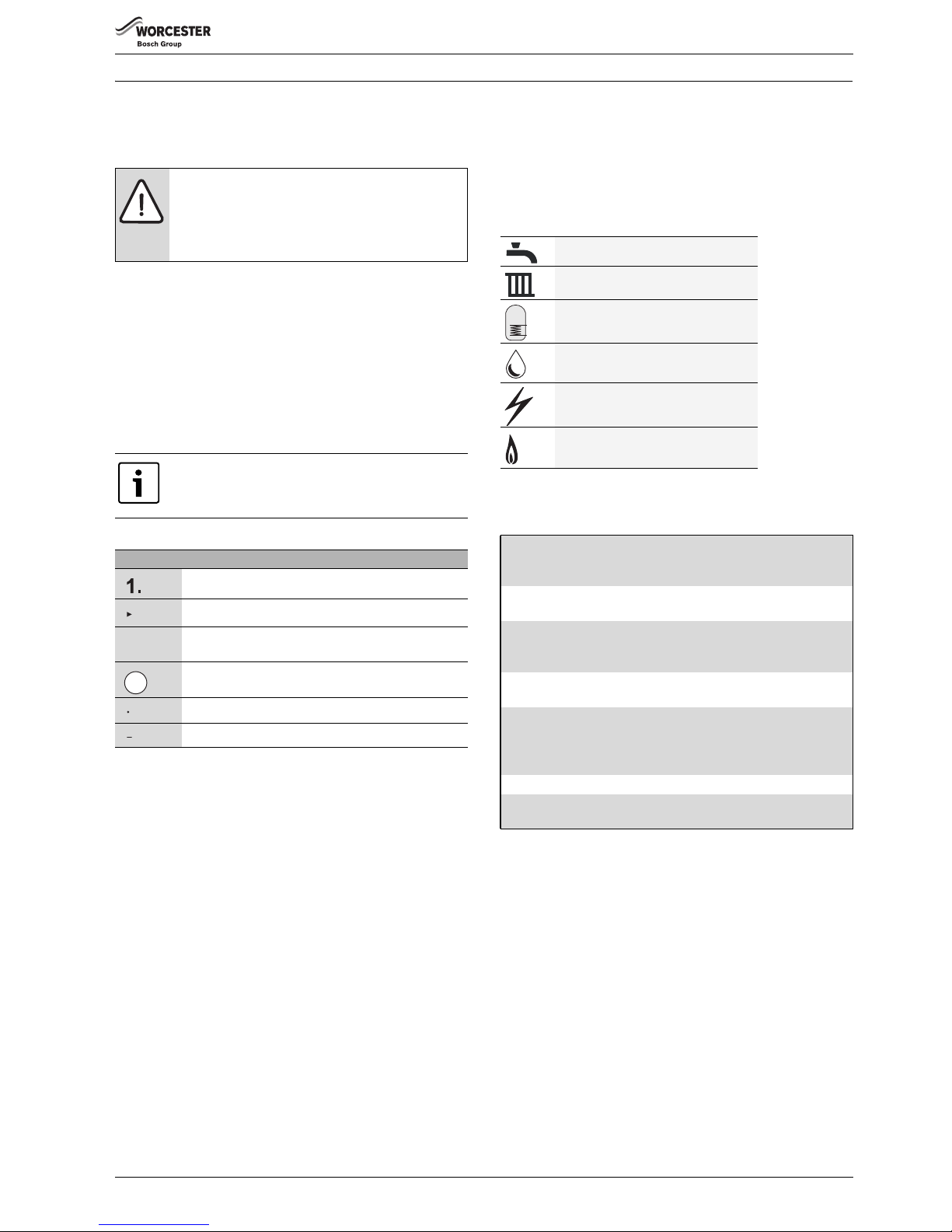
Warnings
The following keywords are defined and can be used in this document:
• NOTICE indicates a situation that could result in damage to property
or equipment.
• CAUTION indicates a situation that could result in minor to medium
injury.
• WARNING indicates a situation that could result in severe injury or
death.
• DANGER indicates a situation that will result in severe injury or
death.
Important information
Additional symbols
Examples of additional symbols used
A numbered step in an action sequence
A sequence of numbered steps or actions carried out in a specific order
to complete a task.
1. First action
2. Second action
3. Third action
etc.
A step in an action sequence
A sequence of defined actions or steps carried out in order to complete
a task.
▶Action
▶ Next action
▶etc
A reference to a related part in the document or to other related
documents.
To refer the reader to a specific figure/table/section within the manual.
e.g. figure 1.
A reference number to identify or refer to a part or item.
In a related figure, items or parts identified by a sequential number.
List entries, first and second levels
• A single component/item
• A component/list, made up of multiple parts/items.
– Sub component or sublist of main component/list.
–etc.
SYMBOLS USED IN THIS MANUAL
PLEASE READ THESE INSTRUCTIONS CAREFULLY BEFORE
STARTING INSTALLATION.
Warnings in this document are identified by a warning
triangle printed against a grey background.
Keywords at the start of a warning indicate the type and
seriousness of the ensuing risk if measures to prevent
the risk are not taken.
This symbol indicates important information where
there is no risk to people or property.
Symbol Meaning
a numbered step in an action sequence
a step in an action sequence
a reference to a related part in the document or to other
related documents
a reference number to identify or refer to a part or item
a list entry
a list entry (second level)
Table 1 Symbols
1
Domestic Hot Water
Central Heating
Hot Water Storage Cylinder
Domestic Cold Water Supply
Electrical Supply
Gas Supply
Table 2 Commonly used symbols
These instructions are applicable to the Worcester appliance model(s)
stated on the front cover of this manual only and must not be used with
any other make or model of appliance.
These instructions apply in the UK and Ireland only and must be
followed except for any statutory obligations.
This appliance must be installed and serviced by a GAS SAFE
registered, competent person. Failure to install correctly could lead to
prosecution.
If you are in any doubt, contact the Worcester Technical helpline
(0330 123 3366).
Please leave these instructions with the completed BENCHMARK
CHECKLIST, (or a certificate confirming compliance with IS 813, Eire
only) and the user manual with the owner or at the gas meter after
installation or servicing.
Distance learning and training courses are available from Worcester.
The BENCHMARK CHECKLIST can be found in the back of this
Installation manual.
Page 4
KEY TO SYMBOLS AND SAFETY PRECAUTIONS
Greenstar Ri
ErP
- 6 720 813 283 (2015/07)4
1.2 Safety precautions
IF YOU SMELL GAS
A gas leak could potentially cause an explosion. If you smell gas, observe
the following rules.
▶ Prevent flames or sparks:
– Do not smoke, use a lighter or strike matches.
– Do not operate any electrical switches or unplug any equipment.
– Do not use the telephone or ring doorbells.
▶ Turn off the gas at the meter or regulator.
▶ Open windows and doors.
▶ Warn your neighbours and leave the building.
▶ Prevent anyone from entering the building.
▶ Well away from the building: call the National Gas Emergency Service
on 0800 111 999.
▶ L.P.G. boilers: Call the supplier’s number on the side of the gas tank.
Appliance operation:
This appliance can be used by children aged from 8 years and above and
persons with reduced physical, sensory or mental capabilities or lack of
experience and knowledge, if they have been given supervision or
instruction concerning the use of the appliance, in a safe way, and
understand the hazards involved.
Children shall not play with the appliance.
Cleaning and user maintenance shall not be made by children without
supervision.
Benchmark places
responsibilities on both
manufacturers and
installers.
The purpose is to ensure
that customers are provided with the correct equipment for their needs,
that it is installed, commissioned and serviced in accordance with the
manufacturer's instructions by competent persons and that it meets the
requirements of the appropriate Building Regulations. The Benchmark
Checklist can be used to demonstrate compliance with Building
Regulations and should be provided to the customer for future
reference.
Installers are required to carry out installation, commissioning and
servicing work in accordance with the Benchmark Code of Practice
which is available from the Heating and Hotwater Industry Council who
manage and promote the scheme.
Visit centralheating.co.uk for more information.
Health and safety
The appliance contains no asbestos and no substances have been used
in the construction process that contravene the COSHH Regulations
(Control of Substances Hazardous to Health Regulations 1988).
Combustion and corrosive materials
Do not store or use any combustible materials (paper, thinners, paints
etc.) inside or within the vicinity of the appliance.
Chemically aggressive substances can corrode the appliance and
invalidate any warranty.
Fittings and modifications
Fitting the appliance and any controls to the appliance may only be
carried out by a competent engineer in accordance with the current Gas
Safety (Installation and Use) Regulations.
Flue systems must not be modified in any way other than as described in
the fitting instructions. Any misuse or unauthorised modifications to the
appliance, flue or associated components and systems could invalidate
the warranty. The manufacturer accepts no liability arising from any
such actions, excluding statutory rights.
Servicing
Advise the user to have the system serviced annually by a competent,
qualified Gas Safe registered engineer. Approved spares must be used
to help maintain the economy, safety and reliability of the appliance.
Important
The service engineer must complete the Service Record on the
Benchmark Checklist after each service.
Flue System
Only use the approved Worcester Condensfit II flue system with this
appliance.
Worcester original spare parts
Only use Worcester original spare parts with this appliance.
Non Worcester original spare parts will invalidate the guarantee (if
applicable) and any warranty.
ØDiameter
NG Natural Gas
LPG Liquid Petroleum Gas
CH Central Heating
DHW Domestic Hot Water
DCW Domestic Cold Water
DWTA Domestic Water Treatment Association
PRV Pressure Relief Valve
NTC Negative Temperature Coefficient (sensor)
IP Ingress Protection
RCD Residual Current Device
TRV Thermostatic Radiator Valve
ECV Emergency Control Valve
WRAS Water Regulations Advisory Scheme
SEDBUK Seasonal Efficiency of Domestic Boilers in the United
Kingdom
Table 3 Abbreviations use in this manual
Page 5

REGULATIONS
Greenstar Ri
ErP
- 6 720 813 283 (2015/07) 5
2Regulations
Installation regulations
Current Gas Safety (Installation & Use) Regulations:
All gas appliances must be installed by a competent person in
accordance with the above regulations.
Failure to install appliances correctly could lead to prosecution.
The appliance must be installed in accordance with, and comply to, the
current: Gas Safety Regulations, IET Regulations, Building Regulations,
Building Standards (Scotland) (Consolidation), Building Regulations
(Northern Ireland), local water by-laws, Health & Safety Document 635
(The Electricity at Work Regulations 1989), EU Regulations No. 811/
2013 - Energy Labelling and any other local requirements.
British standards
Where no specific instruction is given, reference should be made to the
relevant British Standard codes of Practice.
BS7074:1 Code of practice for domestic and hot water supply
BS6891 Installation of low pressure gas pipe work up to 28mm (R1)
BS5546 Installation of gas hot water supplies for domestic purposes
EN12828 Central heating for domestic premises
BS5440:1 Flues and ventilation for gas appliances of rated heating not
exceeding 70kW (net): Flues
BS5440:2 Flues and ventilation for gas appliances of rated heating not
exceeding 70kW (net): Air Supply
BS7593 Treatment of water in domestic hot water central heating
systems
BS6798 Installation of gas fired boilers of rated input up to 70kW (net)
L.P.G. Installations
An appliance using L.P.G. must not be installed in a room or internal
space below ground level unless one side of the building is open to the
ground.
Irish Standards
The relevant Irish standards should be followed, including:
• ECTI National rules for electrical installations
• IS 813:2002 for Domestic Gas Installations.
Timber Framed Buildings
Where the boiler is to be fitted to a timber framed building the guidelines
laid down in BS5440: Part 1 and IGE "Gas Installations in Timber Frame
Buildings” should be adhered to.
Potable Water
All seals, joints and compounds (including flux and solder) and
components used as part of the secondary domestic water system must
be approved by WRAS.
CH Water
Artificially softened water must not be used to fill the central heating
system.
Page 6
APPLIANCE INFORMATION
Greenstar Ri
ErP
- 6 720 813 283 (2015/07)6
3 APPLIANCE INFORMATION
3.1 APPLIANCE
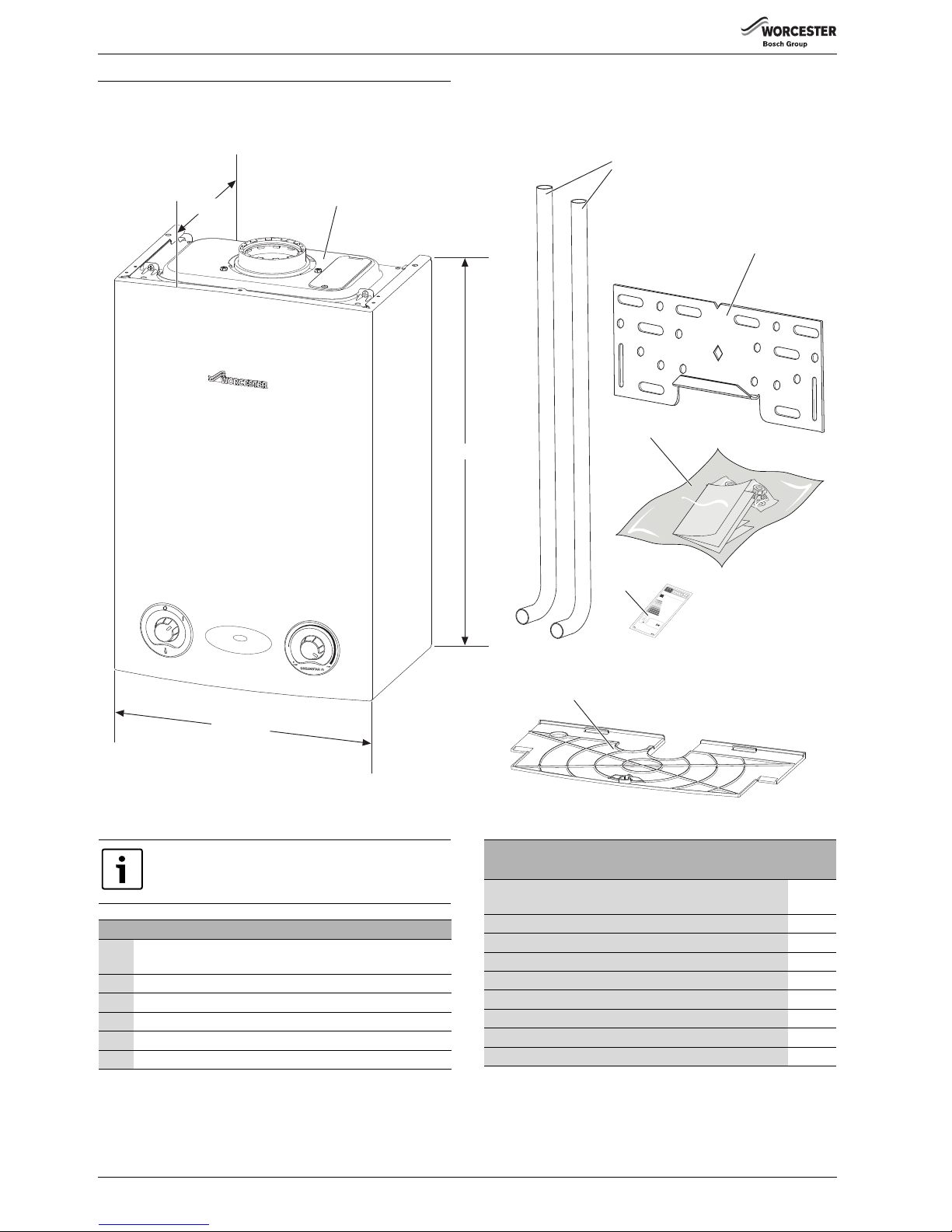
Fig. 1 Appliance
1
2
3
6
6720813283-02.1Wo
390mm
270mm
*600mm to top of case front
590mm*
4
5
Do not use the pre-formed copper pipes supplied with
the boiler for the gas supply.
These copper pipes are for water only.
STANDARD PACKAGE:
1 Wall hung gas fired condensing regular boiler for central
heating and domestic hot water
2 Tail pipes - water only
3 Wall plate
4 Hardware literature pack (see checklist)
5ErP Label
6 Bottom panel and wall mounting template
CHECK LIST
- HARDWARE LITERATURE PACK:
Qty.
Greenstar Ri Installation, Commissioning and Servicing
Instructions
1
Users Instructions 1
Consumer Guarantee Card 1
Sealing Pack: 1
- Compression Nut 22mm 3
- Compression Ring 22mm 3
Elbow assembly pack 1
- Elbow Assembly 1
- Fibre Washer 1
Table 4 Hardware lit pack - checklist
Page 7
APPLIANCE INFORMATION
Greenstar Ri
ErP
- 6 720 813 283 (2015/07) 7
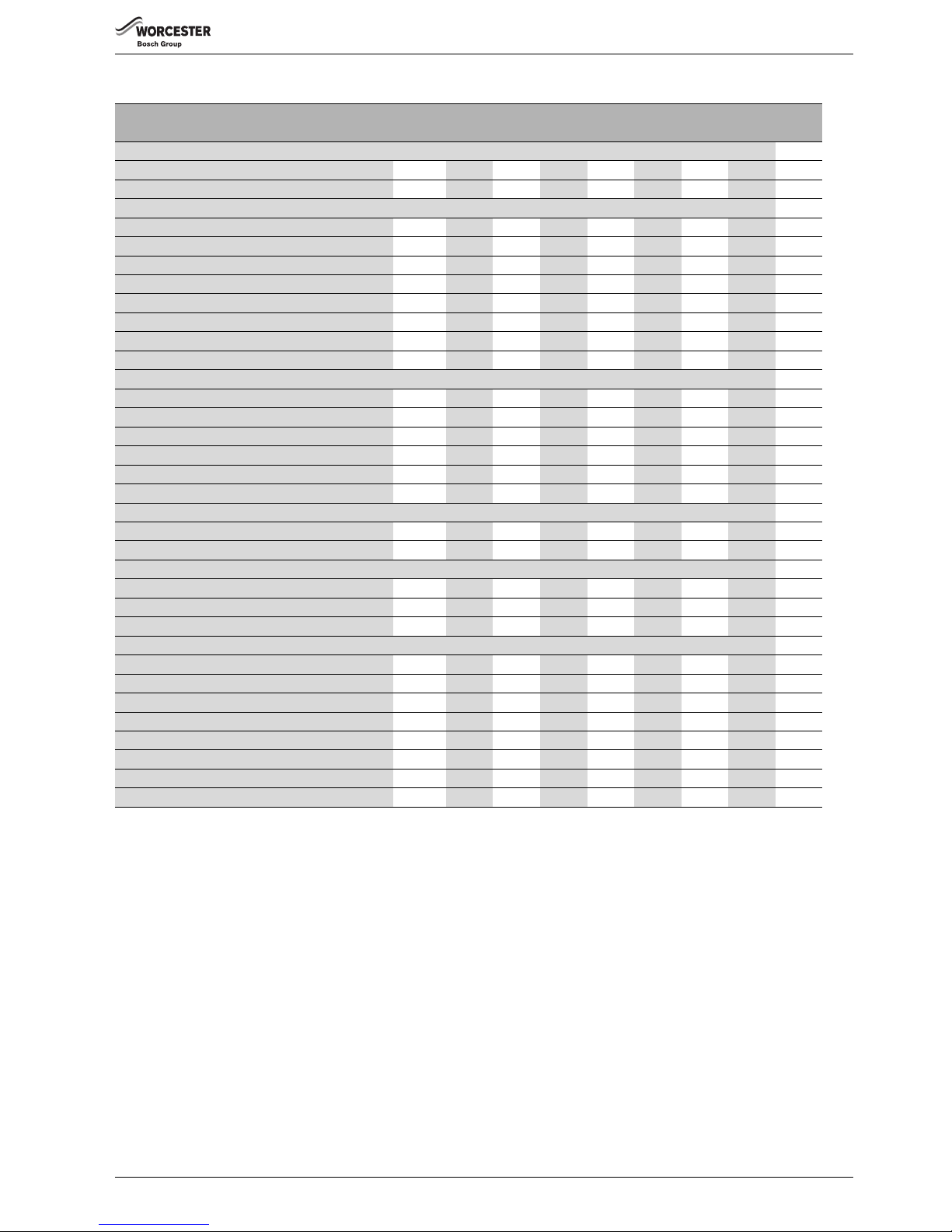
3.2 TECHNICAL DATA
DESCRIPTION NATURAL GAS LPG
UNIT 12Ri 15Ri 18Ri 24Ri 12Ri 15Ri 18Ri 24Ri
Gas flow rate - Max. 10 minutes from lighting
Natural Gas G20 m³/h 1.3 1.63 1.96 2.6 ---Propane Gas (LPG) kg/h ----0.96 1.20 1.44 1.91
Central Heating
Max. rated heat input (net) kW 12.32 15.40 18.48 24.62 12.32 15.40 18.48 24.62
Min. heat input kW 3.45 4.62 5.54 7.38 5.95 5.95 9.64 9.64
Maximum rated heat output 40/30 °C kW 12.85 16.06 19.28 25.67 12.85 16.06 19.28 25.67
Maximum rated heat output 50/30 °C kW 12.74 15.92 19.11 25.45 12.74 15.92 19.11 25.45
Maximum rated heat output 80/60 °C kW 12 15 18 24 12 15 18 24
Maximum flow temperature °C 82 82 82 82 82 82 82 82
Maximum possible flow temperature °C 87 87 87 87 87 87 87 87
Maximum permissible operating pressure bar 2.5 2.5 2.5 2.5 2.5 2.5 2.5 2.5
Flue
Flue gas temp. 80/60 °C, rated/min. load °C 62/56 66/58 70/60 78/63 62/57 66/59 71/61 79/64
Flue gas temp. 40/30 °C, rated/min. load °C 41/33 44/33 48/34 54/35 43/35 46/36 49/37 55/38
CO2 level at max. rated heat output (after 30 min) % 9.65 9.8 9.8 9.8 11.0 11.0 11.0 11.0
CO2 level at min. rated heat output (after 30 min) % 8.65 9.2 9.2 9.2 10.5 10.5 10.5 10.5
NOx class 55455545
NOx rating mg/kWh 39 60 84 66 44 60 84 66
Condensate
Maximum condensate rate l/h 0.93 1.2 1.5 2.0 0.7 0.9 1.2 1.5
pH value, approx. 4.8 4.8 4.8 4.8 4.8 4.8 4.8 4.8
Electrical
Electrical power supply voltage A.C. V 230 230 230 230 230 230 230 230
Frequency Hz 50 50 50 50 50 50 50 50
Maximum power consumption W 37 50 53 54 36 48 52 58
General data
Appliance protection rating IP 20 20 20 20 20 20 20 20
Permissible ambient temperatures °C 0 - 50 0 - 50 0 - 50 0 - 50 0 - 50 0 - 50 0 - 50 0 - 50
Nominal capacity of appliance litre 1.1 1.1 1.1 1.1 1.1 1.1 1.1 1.1
Packaged boiler weight kg 31 31 31 31 31 31 31 31
Total boiler weight kg 27.4 27.4 27.4 27.4 27.4 27.4 27.4 27.4
Lift weight kg 22.6 22.6 22.6 22.6 22.6 22.6 22.6 22.6
SEDBUK band AAAAAAAA
SEDBUK 2005 % 90.1 90.1 90.1 90.2 91.4 91.4 91.4 92.0
Table 5 Technical data Ri
Page 8
APPLIANCE INFORMATION
Greenstar Ri
ErP
- 6 720 813 283 (2015/07)8
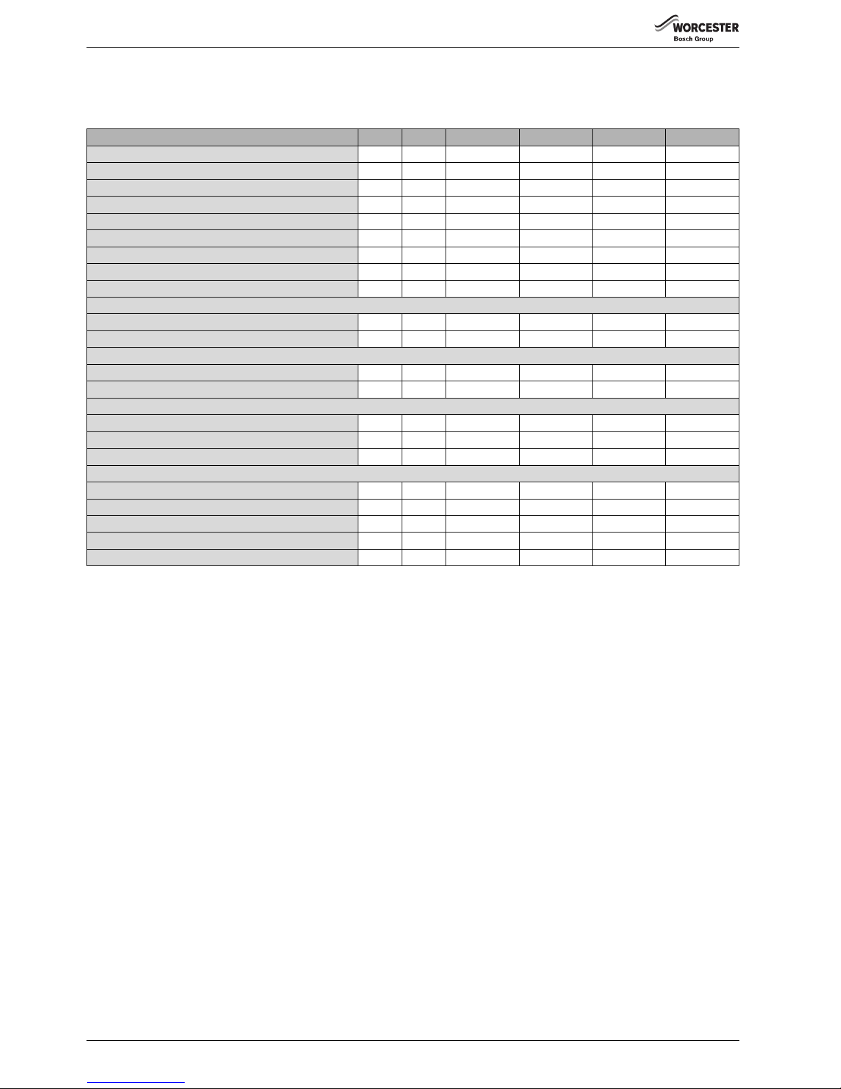
3.3 Energy efficiency
NATURAL GAS APPLIANCES
The following product data satisfy the requirements of the EU Regulations No. 811/2013 and No. 812/2013 supplementing Directive 2010/30/EU.
Product data Symbol Unit 7733600074 7733600072 7733600070 7733600068
Product type – – 12Ri ErP NG 15Ri ErP NG 18Ri ErP NG 24Ri ErP NG
Condensing boiler – – Yes Yes Yes Yes
Low temperature boiler – – No No No No
B1 boiler – – No No No No
Cogeneration space heater (CHP) – – No No No No
Combination heater – – No No No No
Rated heat output P
rated
kW 12 15 18 24
Seasonal space heating energy efficiency
s
% 91919192
Energy efficiency class –– AAAA
Useful heat output
At rated heat output and high temperature regime
1)
1) High-temperature regime means 60 °C return temperature at heater inlet and 80 °C feed temperature at heater outlet.
P
4
kW 12 15 18 24
At 30 % of rated heat output and low temperature regime
2)
2) Low temperature means for condensing boilers 30 °C, for low-temperatur e boilers 37 °C and for other heaters 50 °C return temperature (at heater inlet).
P
1
kW4568
Useful efficiency
At rated heat output and high temperature regime 1)
4
% 87.7 87.7 87.7 88
At 30 % of rated heat output and low temperature regime 2)
1
% 97979797.9
Auxiliary electricity consumption
At full load el
max
kW 0.037 0.05 0.053 0.052
At part load el
min
kW 0.020 0.025 0.027 0.021
In standby mode P
SB
kW 0.006 0.006 0.006 0.006
Other items
Standby heat loss P
stby
kW 0.059 0.059 0.059 0.059
Ignition burner power consumption P
ign
kW0000
Emissions of nitrogen oxides NOx mg/kWh 35 54 76 59
Annual energy consumption Q
HE
kWh---Sound power level, indoors L
WA
dB(A)45485050
Table 6 Product data for energy consumption
Page 9
APPLIANCE INFORMATION
Greenstar Ri
ErP
- 6 720 813 283 (2015/07) 9
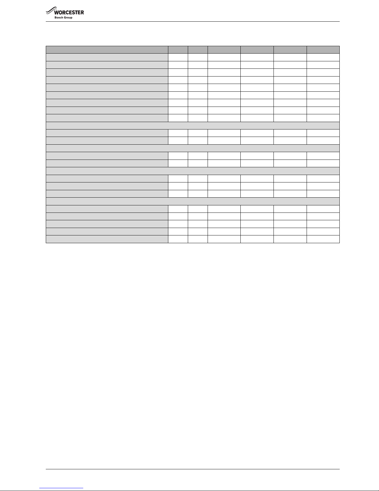
LPG appliances
The following product data satisfy the requirements of the EU Regulations No. 811/2013 and No. 812/2013 supplementing Directive 2010/30/EU.
Product data Symbol Unit 7733600075 7733600073 7733600071 7733600069
Product type – – 12Ri LPG 15Ri LPG 18Ri LPG 24Ri LPG
Condensing boiler – – Yes Yes Yes Yes
Low temperature boiler – – No No No No
B1 boiler – – No No No No
Cogeneration space heater (CHP) – – No No No No
Combination heater – – No No No No
Rated heat output P
rated
kW 12 15 18 24
Seasonal space heating energy efficiency
s
% 91919192
Energy efficiency class –– AAAA
Useful heat output
At rated heat output and high temperature regime
1)
1) High-temperature regime means 60 °C return temperature at heater inlet and 80 °C feed temperature at heater outlet.
P
4
kW 12 15 18 24
At 30 % of rated heat output and low temperature regime
2)
2) Low temperature means for condensing boilers 30 °C, for low-temper ature boilers 37 °C and for other heaters 50 °C return temperature (at heater inlet).
P
1
kW4568
Useful efficiency
At rated heat output and high temperature regime
1)
4
% 87.7 87.7 87.7 88
At 30 % of rated heat output and low temperature regime 2)
1
% 97979797.9
Auxiliary electricity consumption
At full load el
max
kW 0.036 0.048 0.052 0.058
At part load el
min
kW 0.023 0.021 0.026 0.023
In standby mode P
SB
kW 0.006 0.006 0.006 0.006
Other items
Standby heat loss P
stby
kW 0.059 0.059 0.059 0.059
Ignition burner power consumption P
ign
kW0000
Emissions of nitrogen oxides NOx mg/kWh 35 54 76 59
Annual energy consumption Q
HE
kWh---Sound power level, indoors L
WA
dB(A)45485050
Table 7 Product data for energy consumption
Page 10
APPLIANCE INFORMATION
Greenstar Ri
ErP
- 6 720 813 283 (2015/07)10
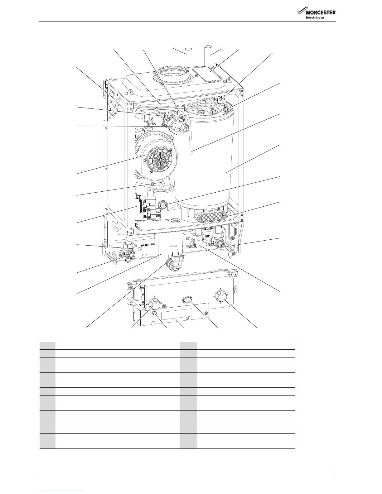
3.4 BOILER MAIN COMPONENTS
1 Air/Gas Manifold 15 Power and fault indicator (blue)
2 Sensor - Boiler flow 16 Wiring connections cover
3 Flow pipe 17 Burner indicator (green)
4 Return pipe 18 Boiler ON/OFF switch
5 Removable servicing panel 19 Condensate connection
6Electrode assembly 20 Syphon / Trap
7 Overheat thermostat 21 Gas inlet connection
8 Silicon tube - Heat Exchanger air vent 22 Mains cable inlet
9Heat Exchanger 23 Gas Valve
10 Flue overheat thermostat 24 Flue air pressure switch connection
11 Access panel - Heat Exchanger/Sump cleaning 25 Fan
12 Return connector with drain point 26 Manual vent point
13 Flow connector 27 Fan pressure test point
14 Boiler Temperature control and Reset knob 28 Air pressure switch
1
23
4
5
6
7
8
9
10
11
12
13
14
15
16
17
18
19
20
21
22
23
24
25
26
27
28
6720804541-01.1Wo
Page 11
PRE-INSTALLATION
Greenstar Ri
ErP
- 6 720 813 283 (2015/07) 11
4 PRE-INSTALLATION
4.1 CLEANING PRIMARY SYSTEMS
BEFORE CLEANING THE SYSTEM:
▶ Ensure that the system and pipe work is in good working order.
▶ Where possible keep the existing boiler/circulating pump in place
when flushing the system.
FOLLOW THE GUIDANCE OF BS7593:
Treatment of water in domestic hot water central heating and also the
flushing guidelines below.
FLUSHING THE SYSTEM
▶ Fill the system with cold water and check for leaks.
▶ Open all drain cocks and drain the system.
▶ Close drain cocks and add a suitable flushing agent compatible with
aluminium at the correct strength for the system conditions in
accordance with the manufacturer‘s instructions.
The pH value of the system water must be less than 8 or the
appliance guarantee will be invalidated.
▶ Circulate the flushing agent before the boiler is started.
▶ Run the boiler/system at normal operating temperature as directed by
the manufacturer of the flushing agent.
▶ Drain and thoroughly flush the system to remove the flushing agent
and debris.
▶ It may be necessary to use a power flushing machine to aid the
cleansing procedure in some circumstances.
▶ Close the drain cocks and refill with fresh water and a suitable
inhibitor.
▶ Vent any air from the boiler and system.
INHIBITOR
Add a suitable inhibitor or combined inhibitor/anti-freeze, if the system
is exposed to freezing conditions, to the heating system in accordance
with the DWTA code of practice and manufacturer‘s guidelines.
WATER TREATMENT PRODUCTS
Suitable water treatment products can be obtain from the following
manufacturers:
ARTIFICIALLY SOFTENED WATER
It is possible to have an Ion exchange water softener fitted to the cold
water system of the property. However, the boiler requires an untreated
cold water connection taken from the mains supply, before the water
softener, to the primary water filling point of the heating system.
Alternatively there are water softening/treatment devices that do not
adjust or alter the pH levels of the water. With these devices it may not
be necessary to provide an untreated water by-pass to the primary water
filling point of the heat system.
4.2 MAINS SUPPLY
4.2.1 ELECTRICAL SUPPLY
• Supply: 230V - 50 Hz, 140 Watts
• Cable: PVC insulated 0.75mm
2
(24 x 0.2mm) temp. rated to 90 °C.
• External 3A fuse to BS1362.
• The appliance must be earthed.
• Do not connected the appliance to a 3 phase supply.
• IP20.
• Wiring must comply with the latest edition of BS 7671 (IET wiring
regulations).
4.2.2 GAS SUPPLY
To ensure that the equipment is in good working order and can meet the
gas flow and pressure requirements, in addition to the demand from any
other appliance being served, the following applies:
• Boilers using Natural Gas (NG) must be connected to a governed
meter.
• Liquid Petroleum Gas (LPG) must be connected to a regulator.
• Installation and connection of the gas supply to the boiler must be in
accordance with BS6891.
• Gas pipe sizing should be calculated to ensure no more than the
permitted mbar drop between the meter/governor to the appliance
inlet. ( Commissioning section).
• The meter or regulator and pipe work to the meter must be checked,
preferably by the gas supplier.
4.3 WATER SYSTEMS AND PIPE WORK
PLASTIC PIPE WORK:
• Any plastic pipe work must have a polymeric barrier with 600mm
(minimum) length of copper pipe connected to the boiler.
• Plastic pipe work used for underfloor heating must be correctly
controlled with a thermostatic blending valve limiting the temperature
of the circuits to approximately 50 °C.
PRIMARY SYSTEMS CONNECTIONS/VALVES:
• All system connections, taps and mixing valves must be capable of
sustaining a pressure up to 3 bar.
• Radiator valves should conform to BS2767:10.
• All other valves should conform to BS1010.
• Thermostatic radiator valves (TRV) must be used on all radiators
within the sleeping accommodation.
The radiator where the room thermostat is sited must be fitted with
lock-shield valves and left open.
• A drain cock is required at the lowest point in the system.
• An air vent is required at all high points in the system.
NOTICE: All the following Pre-Installation sections must
be read and requirements met before starting boiler or
flue installations.
CAUTION: Isolate the mains supplies before starting any
work and observe all relevant safety precautions.
NOTICE: Debris from the system can damage the boiler
and reduce efficiency.
Failure to comply with the guidelines for the use of water
treatment with the appliance will invalidate the
appliance warranty.
NOTICE: Artificially softened water must not be used to
fill the central heating system.
WARNING: Sealing agents
▶ Normally the addition of sealing agents to the system
water is not permitted as this can cause problems
with deposits left in the heat exchanger.
▶ In cases where all attempts to find a micro leak have
failed, Worcester, Bosch Group supports the use of
Fernox F4 leak sealer.
FERNOX 0870 601 5000 or www.fernox.com
SENTINEL 0800 389 4670 or www.sentinel-solutions.net
Page 12
PRE-INSTALLATION
Greenstar Ri
ErP
- 6 720 813 283 (2015/07)12
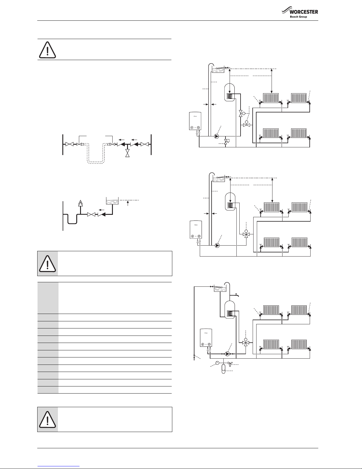
SEALED PRIMARY SYSTEM:
• The CH sealed system must be filled using a WRAS approved filling
loop or comply with figure 2 for system fill.
• An expansion vessel, of a size suitable for the system, must be fitted
as close as possible to the appliance in the central heating return.
• Also fit a pressure gauge, a 3 bar pressure relief valve and stop cock
(fixed cylinder type or sealed system approved connection).
• Do not use galvanised pipes or radiators.
SYSTEM FILL
Fig. 2 System fill/System make-up
S AND Y PLAN SYSTEMS:
FULLY PUMPED SEALED SYSTEM:
The central heating sealed system must be filled using a WRAS approved
filling loop or comply with figure 2 for System fill.
S PLAN LAYOUT
Fig. 3 S plan
Y PLAN LAYOUT
Fig. 4 Y plan
SEALED SYSTEM Y PLAN LAYOUT
Fig. 5 Sealed system
NOTICE: Artificially softened water must not be used to
fill the central heating system.
NOTICE: Bypass
▶ Generally a bypass is not necessary on a Y plan system
as one of the ports is open to flow.
1 Static head -
Minimum static head 250mm measured from the highest
point in the heating system (top surface of the appliance or
the highest point in the heating system) to the water level in
the feed and expansion tank
2 Heating vent (22mm minimum)
3 Primary cold feed (15mm minimum)
4 Diverter/Zone valve
5 Pump, maximum power 90 Watts
6 Automatic bypass
7 Radiator valve (Flow)
8 Lock shield valve (Return)
9 Expansion vessel
10 Pressure gauge
11 3 bar pressure relief valve
12 Stop cock
Table 8 Key to figures 3, 4 & 5
NOTICE: A drain cock should be fitted at the lowest
point of the heating circuit and beneath the appliance.
SYSTEM FILL
CV = Check Valve
SV = Stop Valve
SV SV
Test point
Temporary hose
Hose union
CV
CV
Heating
return
Mains
supply
SYSTEM MAKE UP
AA = Auto Air vent
CV = Check Valve
SV
CV
AA
Make up
vessel
Heating
return
1000 mm (39 in)
above the highest
point of the system.
6720644743-08.2Wo
8
7
1
3
2
4
6
5
150 mm
max
M
M
reset max
6720644744-03.1Wo
8
7
1
3
2
4
5
150 mm
max
reset max
M
6720644744-04.1Wo
MCW
8
7
4
10
12
11
9
5
reset max
M
6720644744-05.1Wo
Page 13
PRE-INSTALLATION
Greenstar Ri
ErP
- 6 720 813 283 (2015/07) 13
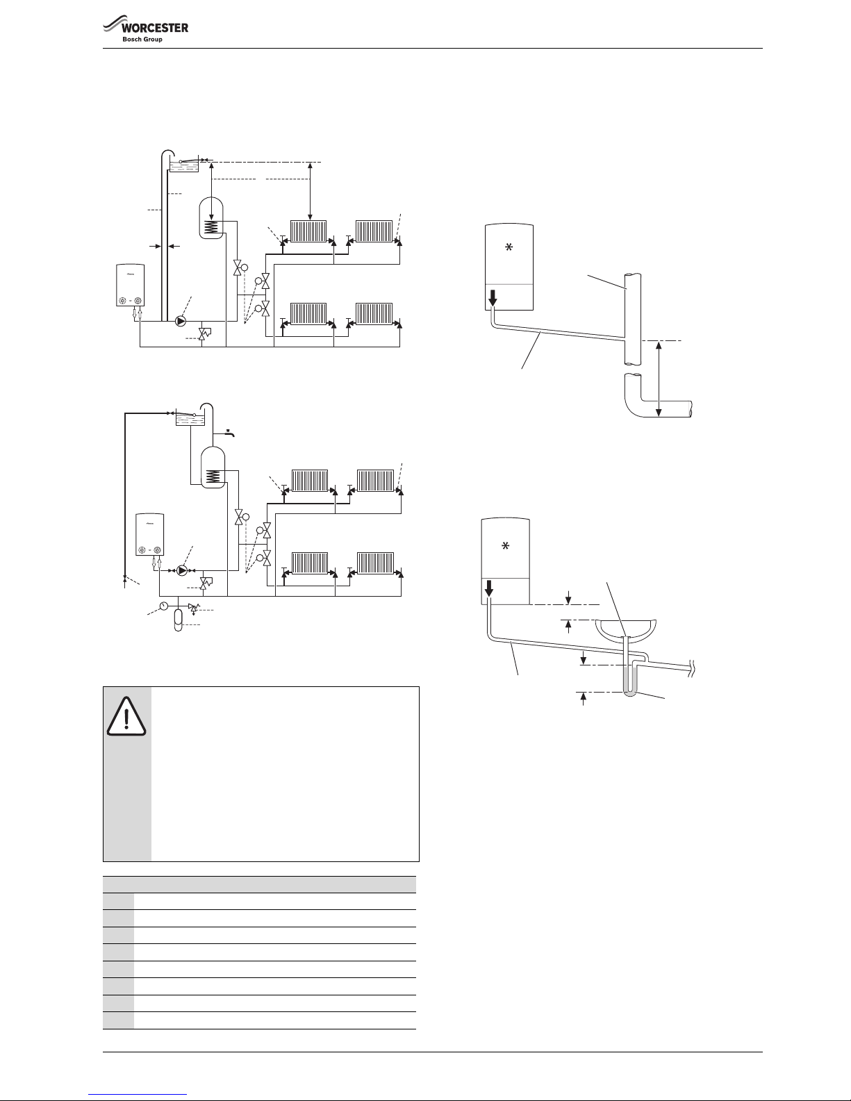
NEW BUILD SYSTEM LAYOUTS
The latest Part L1a regulation for new installations require separate zone
controls for the central heating.
Open vent with two heat zones
Fig. 6
Sealed system with two heat zones
Fig. 7
4.4 CONDENSATE PIPE WORK
4.4.1 INTERNAL CONNECTIONS
In order to minimise risk of freezing during prolonged cold spells, the
following methods of installing condensate drainage pipe should be
adopted, in order of priority.
Wherever possible, the condensate drainage pipe should be routed and
terminated so that the condensate drains away from the boiler under
gravity to a suitable internal foul water discharge point such as an
internal soil and vent stack. A suitable permanent connection to the foul
waste pipe should be used.
Fig. 8 Disposal to soil vent stack
Alternatively if the first option is not possible an internal kitchen or
bathroom waste pipe, washing machine waste pipe etc. can be used.
Ensure that the condensate drain pipe is connected “down stream” of
the waste trap.
Fig. 9 Disposal to a waste pipe
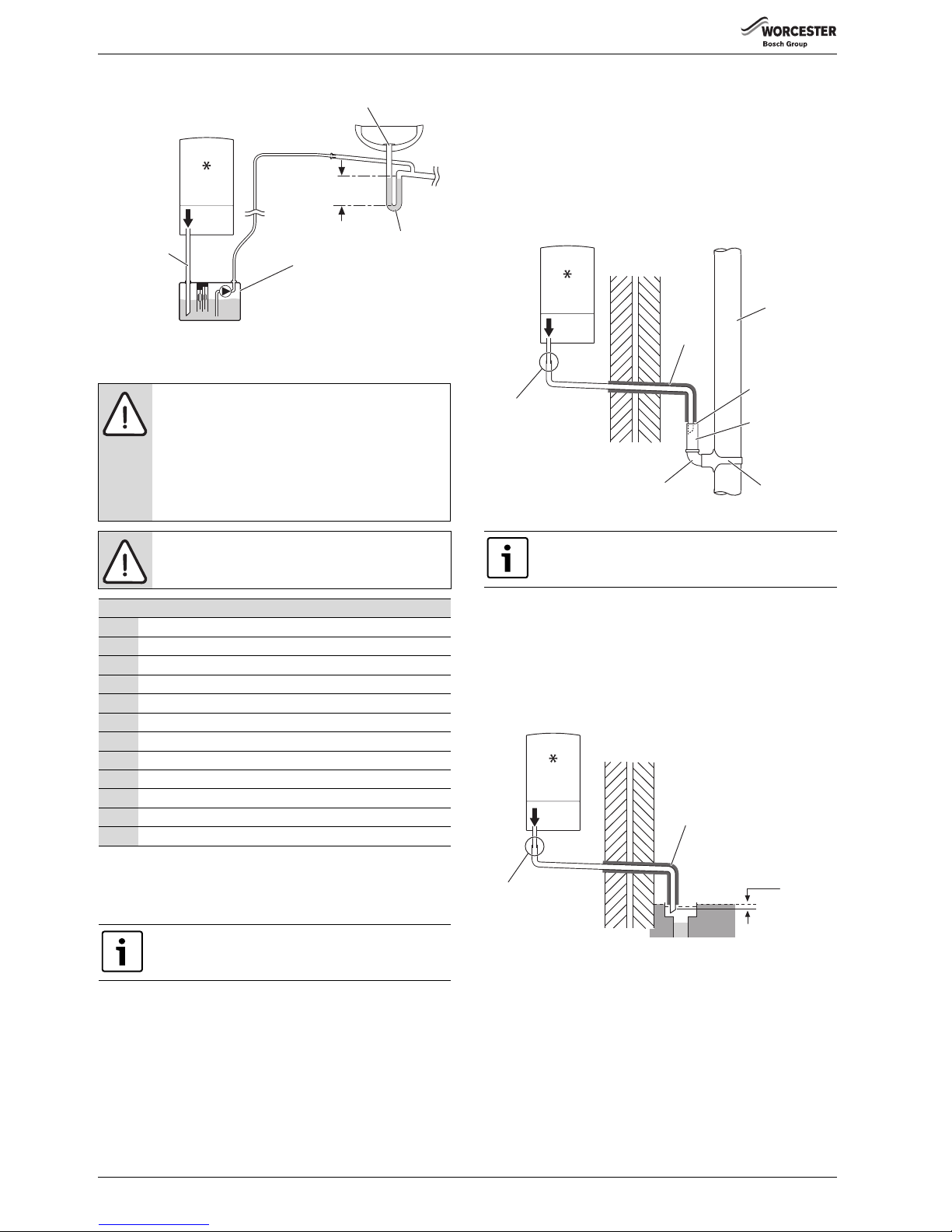
CONDENSATE PUMP
Where “gravity discharge” to an internal termination is not physically
possible, or where very long internal runs would be required to reach a
suitable discharge point, condensate should be removed using a
proprietary condensate pump, of a specification recommended by the
boiler or condensate pump manufacturer.
The pump outlet pipe should discharge to a suitable internal foul water
discharge point such as an internal soil and vent stack, internal kitchen
or bathroom waste pipe, washing machine waste pipe etc. A suitable
permanent connection to the foul waste pipe should be used.
NOTICE:
▶ Where a new or replacement boiler is being installed,
access to an internal “gravity discharge” point should
be one of the factors considered in determining boiler
location.
▶ The condensate pipe must be nominally
22mm Ø plastic pipe.
▶ T he c ond ens ate pi pe w ork mus t fa ll a t le as t 52 mm p er
metre towards the outlet and should take the shortest
practicable route.
▶ Ensure there are no blockages in the pipe run.
Key to condensate illustrations
1 Condensate discharge from boiler
2 Soil and vent stack
3 Minimum 450mm and up to three storeys
4 Visible air break at plug hole
5 Sink or basin with integrated overflow
6 75mm sink waste trap
7Condensate pump
* Condensate trap of 75mm already incorporated into the boiler
6720644744-61.1Wo
8
7
1
3
2
4
6
5
150 mm
max
M
reset max
MM
OPEN VENT LAYOUT
6720644744-62.1Wo
8
7
4
6
5
M
reset max
MM
SEALED SYSTEM LAYOUT
MCW
12
10
11
9
2
22mm Ø
1
3
6720644744-06.3Wo
100mm
75mm
min.
4
5
6
1
22mm Ø
6720644744-07.3Wo
Page 14
PRE-INSTALLATION
Greenstar Ri
ErP
- 6 720 813 283 (2015/07)14
Fig. 10 Condensate pump disposal
4.4.2 EXTERNAL CONNECTIONS
If no other discharge method is possible then the use of an externally run
condensate drainage pipe terminating at a suitable foul water discharge
point, or purpose-designed soak away, may be considered. If this
method is chosen then the following measures should be adopted:
▶ The external run be kept as short as possible and not exceed 3 metres.
▶ The pipe should be run internally as far as possible before going
externally and the pipe diameter should be increased to 32mm before
it passes through the wall to the exterior. The pipe should be insulated
using suitable waterproof and weather resistant insulation, if not
using a CondenseSure siphon.
▶ The external pipe should take the shortest and least exposed route to
the discharge point, and should "fall" as steeply as possible away from
the boiler, with no horizontal runs in which condensate might stand.
▶ The use of fittings, elbows etc. should be kept to a minimum and any
internal “burrs” on cut pipe work should be removed so that the
internal pipe section is as smooth as possible.
FITTING AN EXTERNAL AIR BREAK
• Refer to figure 11 when a rain water down pipe is used to dispose of
condensate.
• An air break must be installed in the 43mm pipe work, between the
boiler condensate outlet and the drainpipe, outside the property, to
avoid flooding during adverse weather conditions.
Fig. 11 Disposal into a rainwater down pipe
Where the pipe terminates over an open drain or gully, the pipe should
terminate below the grating level, but above water level, in order to
minimise “wind chill” at the open end.
The use of a drain cover (such as those used to prevent blockage by
leaves) may offer further protection from wind chill.
Pipe drainage will be improved if the end is cut at 45° as opposed to a
straight cut.
Fig. 12 External disposal
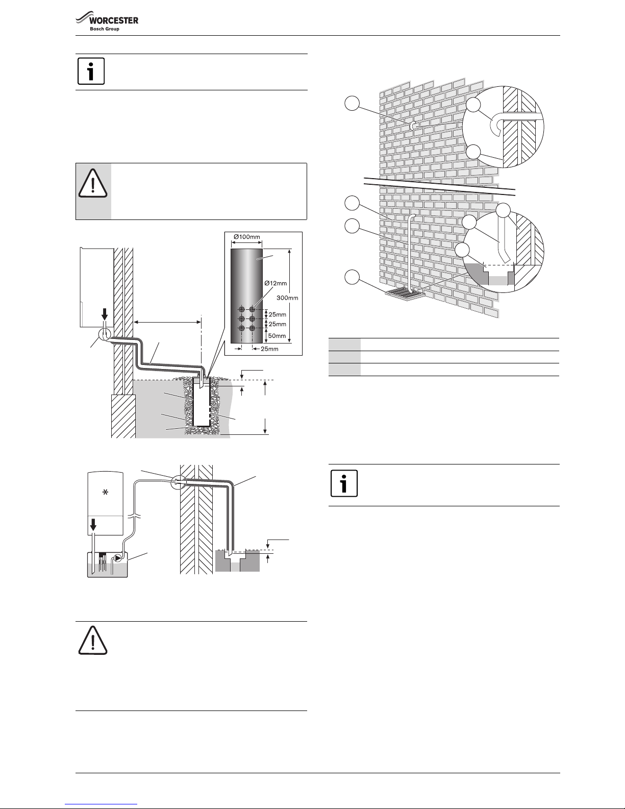
CONDENSATE SOAK AWAY
• The condensate drainage pipe may be run above or below the ground
to the soak away. The examples shown on this page run above ground.
• The soak away must use a 100mm Ø plastic tube with two rows of
three 12mm holes on 25mm centres and 50mm from the bottom of
the tube. The holes must face away from the house.
• The tube must be surrounded by at least 100mm of limestone
chippings to a depth of 400mm.
NOTICE: Freezing conditions
▶ When the position of the boiler prevents internal
routing, we recommend installing a CondenseSure
siphon to significantly reduce the risk of freezing.
▶ Pipe work length should be kept to a minimum and the
route as vertical as possible.
▶ Weather proof insulation must be used, if not using a
CondenseSure siphon.
NOTICE: Condensate waste
▶ Care should be taken when siting a soak-away to avoid
obstructing existing services.
Continued - Key to condensate illustrations
8 PVCu strap on fitting
9 100mm Ø minimum plastic pipe
10 Drainage holes
11 Limestone chippings
12 Bottom of sealed tube
13 Insulate and increase pipe size
14 Pipe work transition
15 External air break
16 Air gap
17 External rain water pipe into foul water
18 43mm 90° male/female bend
* Condensate trap of 75mm already incorporated into the boiler
Use of the CondenseSure siphon will prevent
condensate freezing on a 3 metre straight, 32mm Ø ,
uninsulated pipe at a temperature of -15 °C for 48 hours.
75mm
min.
4
7
5
6
1
22mm Ø
6720644744-08.3Wo
Condensate drainage pipe can be run above or below
ground.
18 8
13
14
17
15
16
1
6720644744-09.3Wo
25mm min.
14
13
1
6720644744-10.3Wo
Page 15
PRE-INSTALLATION
Greenstar Ri
ErP
- 6 720 813 283 (2015/07) 15
In situations where there are likely to be extremes of temperature or
exposure, the use of a proprietary trace-heating system for external pipe
work, incorporating an external frost thermostat, should be considered.
If such a system is used, the requirement to use 32mm pipe does not
apply. However, all other guidance above and the instructions for the
trace heating system, should be closely followed.
Fig. 13 Soak away
Fig. 14 Condensate pump to external disposal
4.5 PRESSURE RELIEF PIPE WORK
• The pressure relief drain pipe (1) from the boiler should be at least
15mm diameter copper pipe and run downwards, away from any
electrical equipment or other hazard, preferably to an external drain
or soak away.
• Pipe (1) should be finished with a partial bend, near the outlet to face
the external wall (as shown) to help prevent freezing.
Fig. 15 Pressure relief pipe work
4.6 BOILER LOCATION AND CLEARANCES
4.6.1 Installation
This appliance is only suitable for installing internally within a property at
a suitable location onto a fixed, rigid surface at least the same size as the
appliance and capable of supporting the appliance weight.
The appliance must be installed where:
• An engineer can gain clear and safe access to work on the product or
component, including making adequate provision for visual
inspection of flues in voids.
• The homeowner can gain clear and safe access to the controls,
check, top up or reset the appliance.
• Products in loft cavities must have permanent fixed lighting, a
permanent fixed retractable ladder and a fixed floor area sufficient to
allow access for normal use and servicing directly under and around
the product and between and the access hatch.
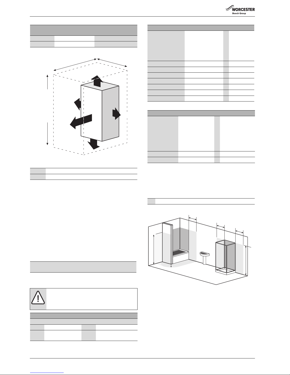
4.6.2 SERVICING CLEARANCES -
VENTILATED COMPARTMENT
Figure 16 shows the minimum space required to install and service the
boiler in a ventilated compartment.
• If a boiler is installed in a compartment with clearances less than
shown in the tables 12, 13, or 14 ventilation is required. Refer to
table 10 for ventilation requirements.
Minimum hole size for the condensate soak away must b e
400mm deep by 300mmØ .
NOTICE: Unheated internal areas.
▶ Internal pipe runs in unheated areas such as lofts,
basements and garages should be treated as external
runs and consideration should be given to using a
CondenseSure siphon.
NOTICE:
▶ The pressure relief valve is a safety device for the
boiler and if activated may discharge boiling water or
steam through the relief valve drain pipe.
▶ Care should be taken when siting the outlet pipe so
that it does not cause an obstruction or discharge
above a window, entrance or other public access
where it could cause a hazard.
13
14
10
500mm min.
25mm min.
400mm
min.
1
12
11
9
6720644744-11.2Wo
9
10
*
25mm min.
14
13
1
7
6720644744-12.3Wo
2Outside wall
1,3 Drain pipe
4External drain
Table 9 Key to fig 15
No surface protection is required against heat transfer
from the appliance.
1
2
3
4
2
3
4
1
2
6720646608-123.1Wo
Page 16
PRE-INSTALLATION
Greenstar Ri
ErP
- 6 720 813 283 (2015/07)16
Fig. 16 Ventilated compartment
4.6.3 COMPARTMENTS:
Follow the requirements of BS6798 and BS5440 Part 2 and note:
• Minimum clearances must be maintained.
• An access door is required to install, service and maintain the boiler
and any ancillary equipment.
• If the boiler is installed in an unventilated airing/storage cupboard,
there is no requirement to make a partition between the boiler and the
storage space as long as the minimum clearances around the boiler
are maintained.
• Ideally, storage should be below the boiler, where the boiler is
mounted in the upper part of the cupboard, whilst maintaining the
clearances given in tables 12, 13, or 14.
4.6.4 BOILER CLEARANCES- UNVENTILATED COMPARTMENTS
4.6.5 INSTALLATION CLEARANCES - UNVENTILATED
COMPARTMENTS
4.6.6 BATHROOMS
The boiler may only be installed outside the shaded area.
Additional RCD (Residual Current Device) protection may be required.
Refer to the latest IET wiring regulations.
Fig. 17 Bathroom installations
Vent position
To room or internal
space
Direct to outside
High level Min. free area 122cm2Minimum free area 61cm
2
Low level Min. free area 122cm2Minimum free area 61cm
2
Table 10 Compartment ventilation
* Minimum clearance to removable door
** Minimum clearance required for servicing
Table 11 Minimum clearances
The tables below show the options for the minimum space required to
install and service the boiler inside an unventilated compartment.
CAUTION: CLEARANCES
▶ Top and bottom clearances must not be reduced
below the values shown in table 12 as they are the
minimum clearances required for servicing.
Unventilated Compartment Installation Clearances (millimetres)
Suggested total unventilated compartment minimum clearances are:
Side Above Below Front (to removable door)
400mm 170mm approx.
(30mm above elbow)
200mm 100mm
Table 12 Minimum unventilated compartment clearances
6720643895-121.2Wo
+ 30 mm
above elbow
930 mm 410 mm
20 mm*
600 mm**
5 mm
Using 100 mm
ue kit
1080 mm
Using 125 mm
ue kit
1100 mm
200 mm
5 mm
If Side Clearances are Reduced (millimetres)
If total side clearance is
reduced to: (Combined
left and right
clearances excluding
the boiler)
Increase height
clearances to (approx.):
(Combined top &
bottom clearances
excluding the
appliance)
ORFront clearance
(to removable
door) must be
increased to:
350 441 129
300 523 161
250 617 200
200 717 243
150 856 295
100 1012 358
50 1202 434
Table 13 Reduced side clearances
If Front Clearance is Reduced (millimetres)
If front clearance
(to removable
door) is reduced
to:
Increase overall height
clearances to
(approx.):
(Combined top and
bottom clearances
excluding the
appliance)
ORIncrease total side
clearance to:
(Combined left and
right clearances
excluding the
appliance)
50mm 511mm 505mm
25mm 596mm 569mm
Table 14 Reduced front clearances
2* Without the end wall, zone 2 must extend 600mm from the bath
6720646608-124.3Wo
2*
Radius 600mm
1
2
1
2
2
1
600mm
600mm
600mm
2250mm
2250mm
2*
Page 17
PRE-INSTALLATION
Greenstar Ri
ErP
- 6 720 813 283 (2015/07) 17
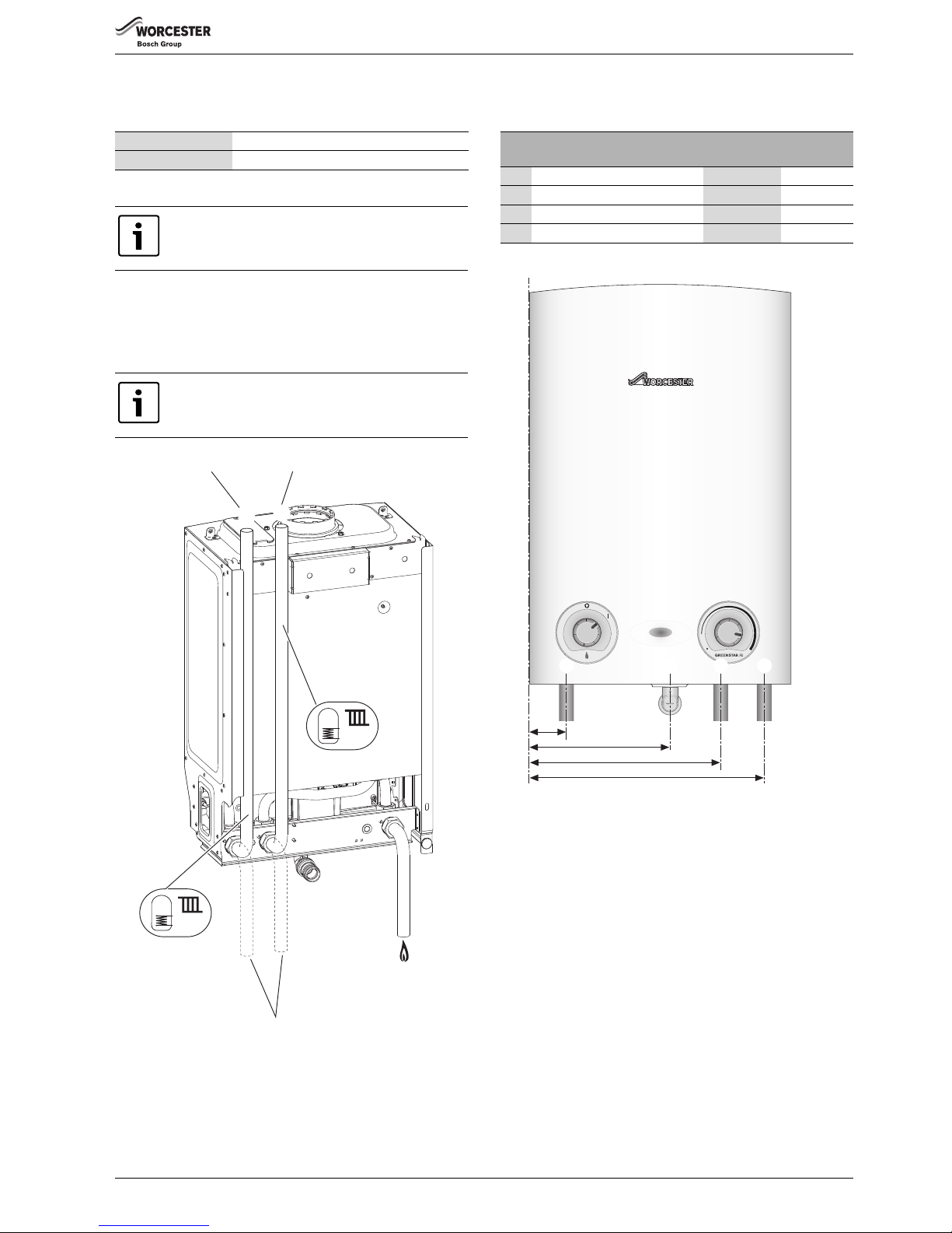
4.7 PLUMBING MANIFOLD
4.7.1 CONNECTIONS
Use the fittings supplied in the Hardware literature pack:
• Use the 22mm copper pipes (1 & 2) provided with the appliance, as
shown in the diagram opposite.
• If the flow and return pipes are to be run behind the appliance it
maybe an advantage to connect the pipes before hanging on the wall
especially if space is limited.
Fig. 18 Plumbing manifold
Fig. 19 Pipe work dimensions
Heating System 22mm compression fittings
Gas 22mm compression fittings
Do not use the pre-formed copper pipes supplied with
the boiler for the gas supply.
These copper pipes are for water only.
Further guidance on pipe routing can be found printed
on the boiler template (supplied with the boiler).
1
2
4
3
3
4
6720644744-13.1Wo
Pipes in alternative position
Return Flow
# Function
From left
case edge
Diameter of
pipe
1Gas 55mm 22mm
2Condensate 210mm 22mm
3Cylinder & CH Flow 285mm 22mm
4 Cylinder & CH Return 350mm 22mm
Table 15 Key to figures 18 & 19
6720644744-17.1Wo
reset max
1 2 3 4
Page 18
PRE-INSTALLATION
Greenstar Ri
ErP
- 6 720 813 283 (2015/07)18
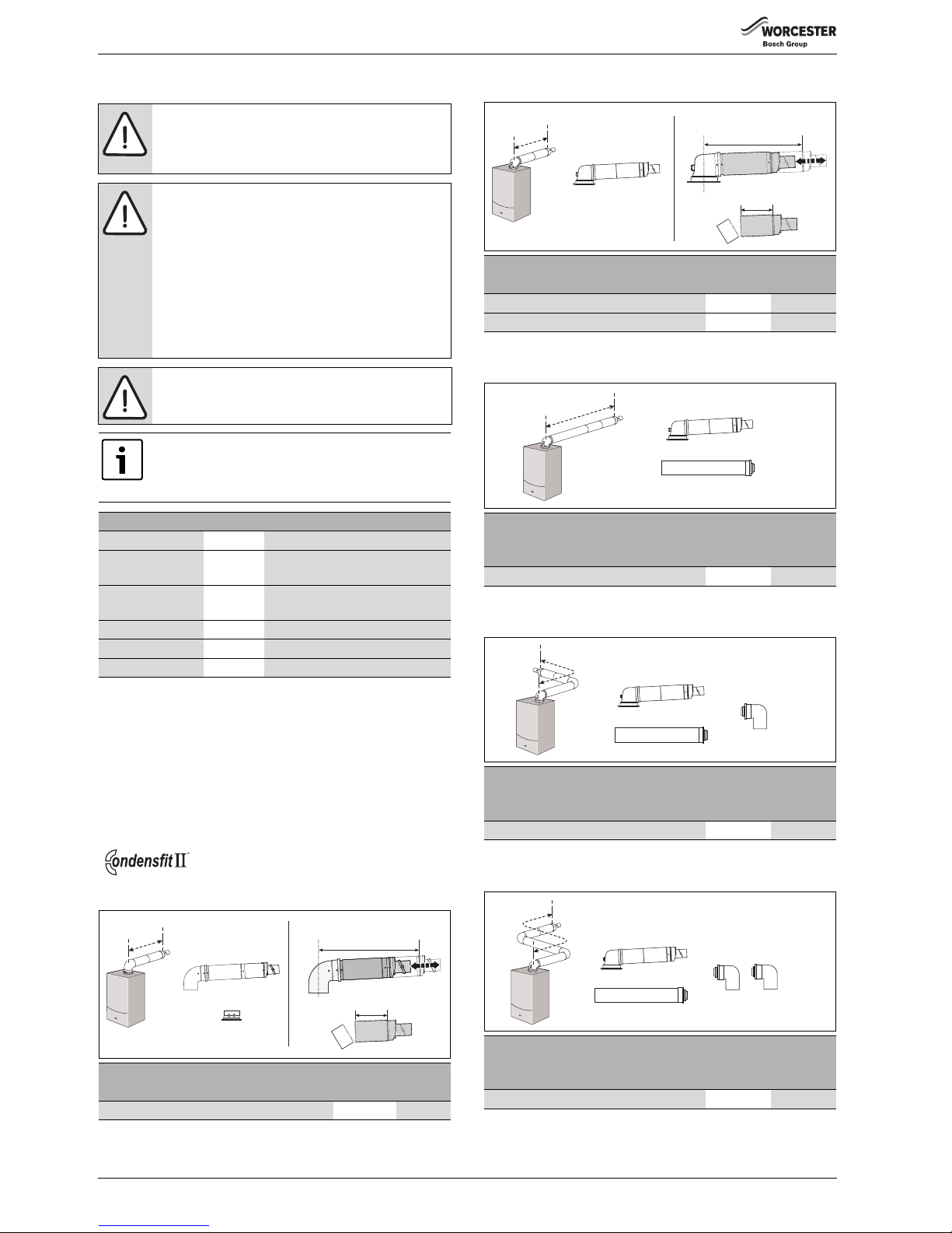
4.8 FLUE OPTIONS
4.8.1 Flue lengths
The flue systems have different maximum flue lengths
The Greenstar series has the option of two horizontal 60/100 RSF
(telescopic and longer telescopic) and one horizontal 80/125 RSF
(telescopic) flue system and two vertical RSF (60/100 or 80/125) flue
systems:
Refer to the following example Flue options for the maximum flue
lengths.
Horizontal high level flue assembly
TELESCOPIC HORIZONTAL FLUE ASSEMBLY
Extended horizontal flue
Horizontal flue with additional elbow (1 x 90 ° bend)
Horizontal flue with additional elbows (2 x 90 ° bends)
WARNING: Flue systems
▶ Only use Worcester, Bosch approved flue systems, no
other manufacturer’s flue systems have been
approved for use with Worcester appliances.
CAUTION: Non accessible flue systems:
▶ Where a flue system is not going to be accessible,
provision must be made for service and inspection.
▶ Voids containing concealed flues must have at least
one inspection hatch no less than 300mm square.
▶ Flue joints within the void must not be more than 1.5
metres from the edge of the inspection hatch.
▶ Inspection hatches should be located at changes of
direction.
▶ If this is not possible, bends should be viewable from
both directions.
NOTICE: Effective flue lengths:
▶ each 90° bend is equivalent to 2 metres of straight flue
▶ each 45° bend is equivalent to 1 metre of straight flue
Plume management kits are available for the 60/100
horizontal flue system.
Refer to the manual supplied with the plume
management kits for complete installation instructions
Part number Flue Description
7 716 191 082 60/100 Telescopic horizontal flue assembly
7 716 191 171 60/100 Longer telescopic horizontal flue
assembly
7 733 600 048 60/100 Horizontal high level telescopic flue
kit
7 719 003 702 80/125 Telescopic horizontal flue assembly
7 719 002 430 60/100 Vertical flue assembly
7 719 002 431 80/125 Vertical flue assembly
Table 16 Flue kit part numbers
Flue length (mm)
60/100 80/125
Horizontal high level telescopic flue assembly 202 - 603 N/A
Table 17
6720806945-29.1Wo
383 mm - 603 mm
60/100 mm
130 mm Min
Flue length (mm)
60/100 80/125
Telescopic horizontal flue assembly 180 - 570 405 - 600
Longer telescopic horizontal flue assembly 570 - 790 N/A
Table 18
Maximum flue length
(mm)
60/100 80/125
Extended horizontal flue 4,600 13,000
Table 19
Maximum flue length
(mm)
60/100 80/125
Horizontal flue with 1 x 90° bend 2,600 11,000
Table 20
Maximum flue length
(mm)
60/100 80/125
Horizontal flue with 2 x 90° bends N/A 9,000
Table 21
6720806945-18.1Wo
350 mm - 570 mm
60/100 mm
130 mm Min
6720806945-19.1Wo
6720806945-20.1Wo
6720806945-21.1Wo
Page 19
PRE-INSTALLATION
Greenstar Ri
ErP
- 6 720 813 283 (2015/07) 19
High level horizontal flue
High level horizontal flue with additional elbows
High level horizontal flue with additional elbows
Vertical balanced flue assembly
Vertical balanced flue with elbow offset (2 x 90 ° bends)
Vertical balanced flue with elbow offset (2 x 45 ° bends)
Maximum flue length
(mm)
60/100 80/125
High level horizontal flue 4,600 13,000
Table 22
Maximum flue length
(mm)
60/100 80/125
High level horizontal flue with 2 x 90° bends 2,600 11,000
Table 23
Maximum flue length
(mm)
60/100 80/125
High level horizontal flue with 3 x 90 ° bends N/A 9,000
Table 24
6720806945-22.1Wo
6720806945-23.1Wo
6720806945-24.1Wo
Maximum flue length
(mm)
60/100 80/125
Vertical balanced flue assembly 6,400 15,000
Table 25
Maximum flue length
(mm)
60/100 80/125
Vertical balanced flue with 2 x 90° bends 2,400 11,000
Table 26
Maximum flue length
(mm)
60/100 80/125
Vertical balanced flue with 2 x 45° bends 4,400 13,000
Table 27
6720806945-25.1Wo
A = 300 mm
B = 500 mm
6720806945-26.1Wo
6720806945-27.1Wo
Page 20
PRE-INSTALLATION
Greenstar Ri
ErP
- 6 720 813 283 (2015/07)20
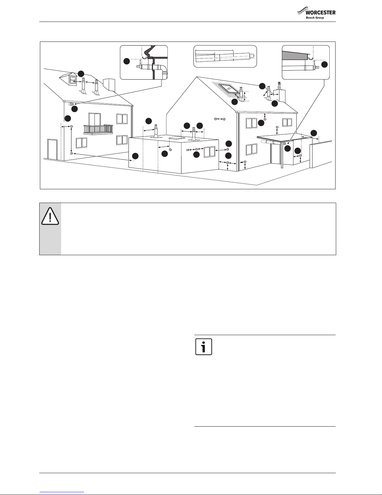
4.9 FLUE TERMINAL POSITIONS
Fig. 20 Flue terminal positions
Key to illustration
1. 300mm adjacent to a boundary line.
2. The dimension below eaves, gutters, pipes and drains can be
reduced to 25mm, as long as the flue terminal is extended to clear
any overhang. External flue joints must be sealed with suitable
silicon sealant.
3. 1,500mm between a vertical flue terminal and a window or dormer
window.
4. 1,200mm between terminals facing each other.
5. Vertical flue clearance, 300mm adjacent to a boundary line unless it
will cause a nuisance. BS 5440:Part 1 recommends that care is
taken when siting terminal in relation to boundary lines
6. 600m distance to a boundary line, unless it will cause a nuisance.
BS 5440:Part 1 recommends that care is taken when siting terminal
in relation to boundary lines.
7. 600mm minimum clearance from a skylight to a vertical flue.
8. Vertical flue clearance, 500mm to non-combustible building
material, and 1,500mm clearance to combustible building material.
9. 300mm above, below and either side of an opening door, air vent or
opening window.
10. 600mm diagonally to an opening door, air vent or opening window.
11. 300mm to an internal or external corner. This does not apply to
building protrusions less than 450mm.
12. 2,000mm below a Velux window, 600mm above or to either side of
the Velux window.
13. 400mm from a pitched roof or 500mm in regions with heavy snow
fall.
14. 500mm clearance to any vertical structure on a roof, 600mm to
room sealed flue or 1,500 to an open flue.
15. 200mm below eaves and 75mm below gutters, pipe and drains.
16. The dimension below eaves, balconies and car ports can be
reduced to 25mm, as long as the flue terminal is extended to clear
any overhang. External flue joints must be sealed with suitable
silicon sealant.
17. Flue clearance must be at least 300mm from the ground. Terminal
guards must be fitted if the flue is less than 2 metres from the
ground or if a person could come into contact with the flue
terminal.
18. 600mm distance to a surface facing a terminal, unless it will cause
a nuisance. BS 5440: Part 1 recommends that care is taken when
siting terminals in relation to surfaces facing a terminal.
16
600
300
200
300
1,200
Boundary Line
1,500
1,500
All measurements in millimetres
2
1
12
11
10
9
5
18
7
6
13
15
4
3
17
14
300
300
300
300
300
300
300
500
600
300
600
600
400
300
25
8
300
500
600
6720643895-13.3Wo
300
25
2
25
16
2m
1m
52mm
104mm
NOTICE:
▶ All measurements are the minimum clearances required.
▶ Terminals must be positioned so to avoid combustion products entering the building.
▶ Support the flue at approximately one metre intervals and at a change of direction, use suitable brackets and fittings.
(flue bracket 100mm part number: 7 716 191 177,
flue brackets 100mm x 6 part number: 7 716 191 178,
flue bracket 125mm part number: 7 716 191 179).
Note:
▶ Installations in car ports are not recommended.
▶ The flue cannot be lower than 1,000mm from the top
of a light well due to the build up of combustion
products.
▶ Dimensions from a flue terminal to a fanned air inlet
to be determined by the ventilation equipment
manufacturer.
▶ A flue terminal guard should be fitted over a terminal,
if persons could come into contact with the terminal,
or it could be subject to damage and where the
terminal is less than 2,000mm from the finished floor
level.
Page 21
PRE-INSTALLATION
Greenstar Ri
ErP
- 6 720 813 283 (2015/07) 21
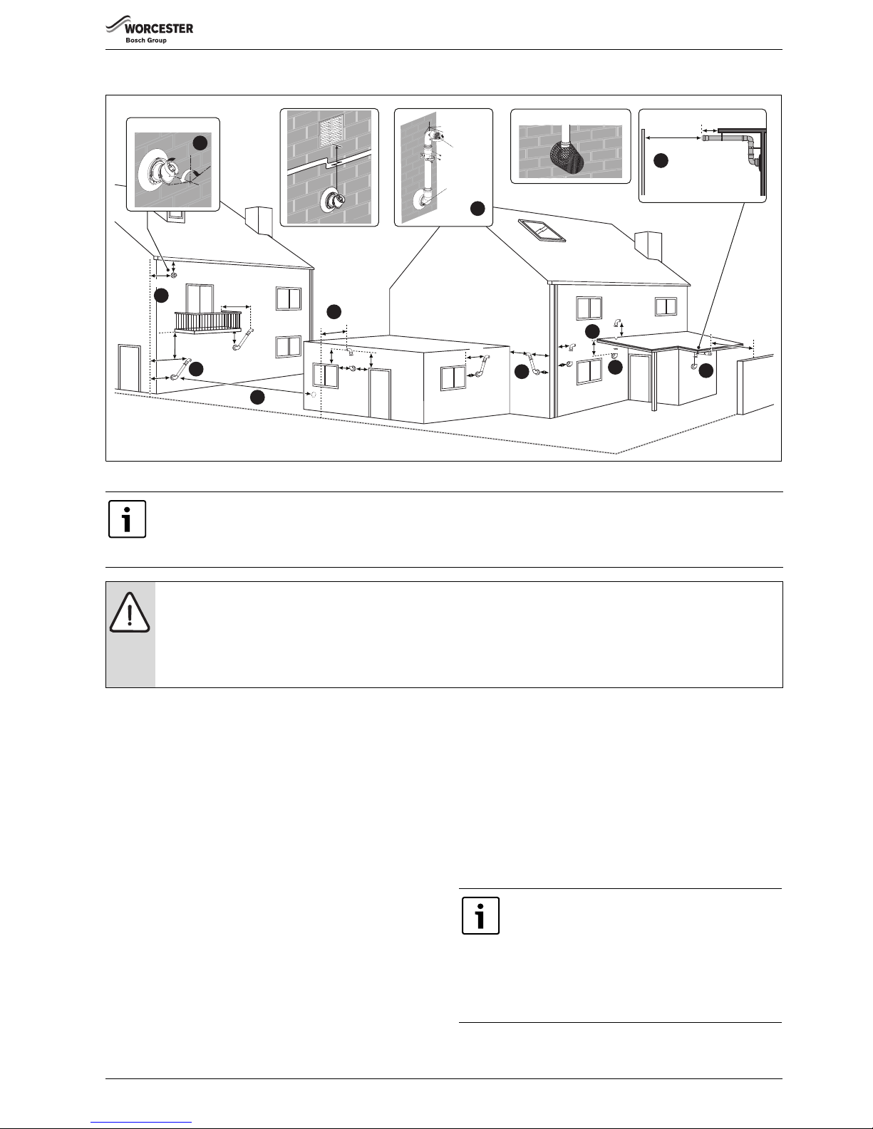
4.10 PLUME MANAGEMENT TERMINAL POSITIONS
Fig. 21 Plume terminal positions
Key to illustration
1. This feature allows some basic plume re-direction options on a
standard telescopic horizontal flue terminal.
300mm minimum clearances to a opening e.g. window.
However the minimum clearances to an opening in the direction that
the plume management is facing, must be increased to 1,500mm.
Where the flue is less than 150mm to a drainpipe and plume redirection is used the deflector should not be directed towards the
drainpipe.
2. 300mm adjacent to a boundary line.
3. Plume Management kit air intake can be reduced to 150mm
providing the flue exhaust outlet is no less than 300mm adjacent to
a boundary line.
4. 1,200mm between terminals facing each other.
5. 600mm distance to a boundary line, unless it will cause a nuisance.
BS 5440:Part 1 recommends that care is taken when siting terminal
in relation to boundary lines.
6. Using a Plume Management kit the air intake measurement can be
reduced to 150mm providing the flue exhaust outlet has a 300mm
clearance. The initial horizontal run from the terminal elbow must
have a minimum 10° fall back, (stop tabs in the elbow prevent less
than 10°) to the appliance for proper disposal of condensate. Any
further horizontal runs can be 3°.
– For details on specific lengths see relevant appliance Technical &
Specification information.
7. Internal/external corners. The air intake clearance can be reduced to
150mm providing the flue exhaust outlet has a 300mm clearance.
8. Clearances no less than 200mm from the lowest point of the
balcony or overhang.
9. 1,200mm from an opening in a car port on the same wall e.g. door
or window leading into the dwelling.
10. 600mm distance to a surface facing a terminal, unless it will cause a
nuisance. BS 5440: Part 1 recommends that care is taken when
siting terminals in relation to surfaces facing a terminal.
200
300
150
200
8
4
5
3
2
9
200
600
All measurements in millimetres
300
300
150
150
300
300
25
25
150
1,200
300
200
10
100
600
Plume re-direction:
180°
±80°
1
7
±45°
Flue Exhaust
Outlet
Air Intake
6
10
Boundary Line
6720643895-14.2Wo
150
300
300
Flue terminal guard 7 716 191 176
600
1,500
Maximum and minimum plume management lengths:
▶ A minimum distance of 500mm must be maintained between the plume management outlet and the flue air intake.
▶ The maximum plume management length is 4.5 metres for the appliances detailed on the front of this manual.
▶ The 45 ° bend is equivalent to 0.75 metres of straight plume management and the 90° bend is equivalent to 1.5 metres.
NOTICE:
▶ All measurements are the minimum clearances required.
▶ Refer to previous page for all concentric flue terminal positions unless the flue position is specified on the figure above “Plume
terminal positions”.
▶ Terminals must be positioned so to avoid combustion products entering the building.
▶ Support the flue at approximately one metre intervals and at a change of direction, use suitable brackets and fittings.
Note:
▶ Installations in car ports are not recommended.
▶ The flue cannot be lower than 1,000mm from the top
of a light well due to the build up of combustion
products.
▶ Dimensions from a flue terminal to a fanned air inlet
to be determined by the ventilation equipment
manufacturer.
Page 22
INSTALLATION
Greenstar Ri
ErP
- 6 720 813 283 (2015/07)22
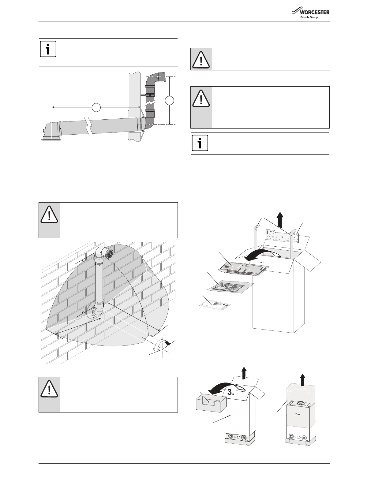
4.10.1 Determine the plume management system length
Fig. 22 Effective lengths L and M
Minimum plume management length
The minimum plume length should be calculated to ensure that the air
inlet and exhaust have a minimum distance of 500mm between them
( figure 23).
The plume management can be in any configuration, within the
parameters of the plume management installation instructions, as long
as it does not terminate inside the shaded area.
Fig. 23 Terminal exclusion zone
Maximum plume management length
The Greenstar Ri range appliances can use up to 4,500mm of plume
management regardless of flue length.
5 INSTALLATION
5.1 UNPACKING THE WALL FRAME & ANCILLARY ITEMS
Remove the straps and open the top of the boiler packaging.
1. Remove the two 22mm water pipes (1)
2. Remove the following items:
– Wall mounting plate (2).
– Wall mounting template and bottom panel (3).
– Literature pack and pipe connectors and olives (4).
– ErP label (5)
Fig. 24 Unpacking 1
3. Remove the top carton (5).
4. Remove the outer cardboard sleeve (6).
5. Remove the plastic cover (7).
Fig. 25 Unpacking 2
Note: Measurement M plume length
▶ M must be a minimum of 500mm and must not exceed
4,500mm for a 60mm plume management system
used with the horizontal Ø 60/100mm flue.
WARNING: Minimum plume management length.
The minimum distance of 500mm must be maintained
between air inlet and exhaust.
▶ Do not terminate the plume management inside the
shaded area shown in figure 23
NOTICE: Cutting the 500mm pipe
If the 500mm plume management pipe kit is cut, an
additional elbow will be required to join the pipework.
▶ The Plume management extension kit contains the
components required for such a configuration.
6720803800-09.1Wo
M
L
67206646610-75.1Wo
5
0
0
m
m
5
0
0
mm
5
00
mm
±80°
WARNING: All the previous “Pre-Installation” sections
must be read and the requirements met before starting
boiler or flue installation.
CAUTION: LIFTING AND CARRYING
▶ Only lift a manageable weight, or ask for help.
▶ Bend the knee and keep the back straight with feet
apart, when lifting or putting down heavy objects.
▶ DO NOT lift and twist at the same time.
▶ Lift and carry object close to the body.
Do not use the pre-formed water pipes on the gas
supply, they must only be used for water.
6720813283-03.1Wo
1
2
3
4
2.
1.
5
6720644744-15.2Wo
3.
4.
5
6
5.
7
Page 23
INSTALLATION
Greenstar Ri
ErP
- 6 720 813 283 (2015/07) 23
▶ Flatten the outer cardboard sleeve and place on the floor behind the
boiler.
▶ Lay the boiler on its back on the cardboard.
▶ Remove the bottom tray.
IMPORTANT HANDLING INSTRUCTIONS:
• It is advised that two people are used to carry the carton from the van
to the point of delivery.
• Once the carton has been delivered, remove the outer carton. Care
should be taken when releasing the straps. If a sharp implement is
used, ensure the outer carton is not pierced and that the implement is
used in such a way that it will not cause personal injury.
• All sharp objects must be covered or the blade retracted after use and
put away in a safe place. The wall mounting frame, Installer pack,
template and bottom panel can now be removed. Care should be
taken when lifting the boiler from the base and the proper technique
for safe lifting of any heavy object must be strictly observed.
Additional requirements for roof space installation:
• The boiler must be unpacked before ascending the steps to loft space.
• Two sets of steps should be used.
• Two people should share the lifting of the boiler up to the loft hatch,
where the boiler is entered into the loft space, tilted, and slid on its
back into the loft.
• Once the appliance is removed from its packaging check the contents
against the packing list.
Before installing the appliance, ensure that the system has been
cleaned as explained on page 11.
5.2 WALL MOUNTING TEMPLATE & FLUE OPENING
SAFETY:
All relevant safety precautions must be undertaken. Protective clothing,
footwear, gloves and safety goggles must be worn as appropriate.
FIXING THE MOUNTING FRAME:
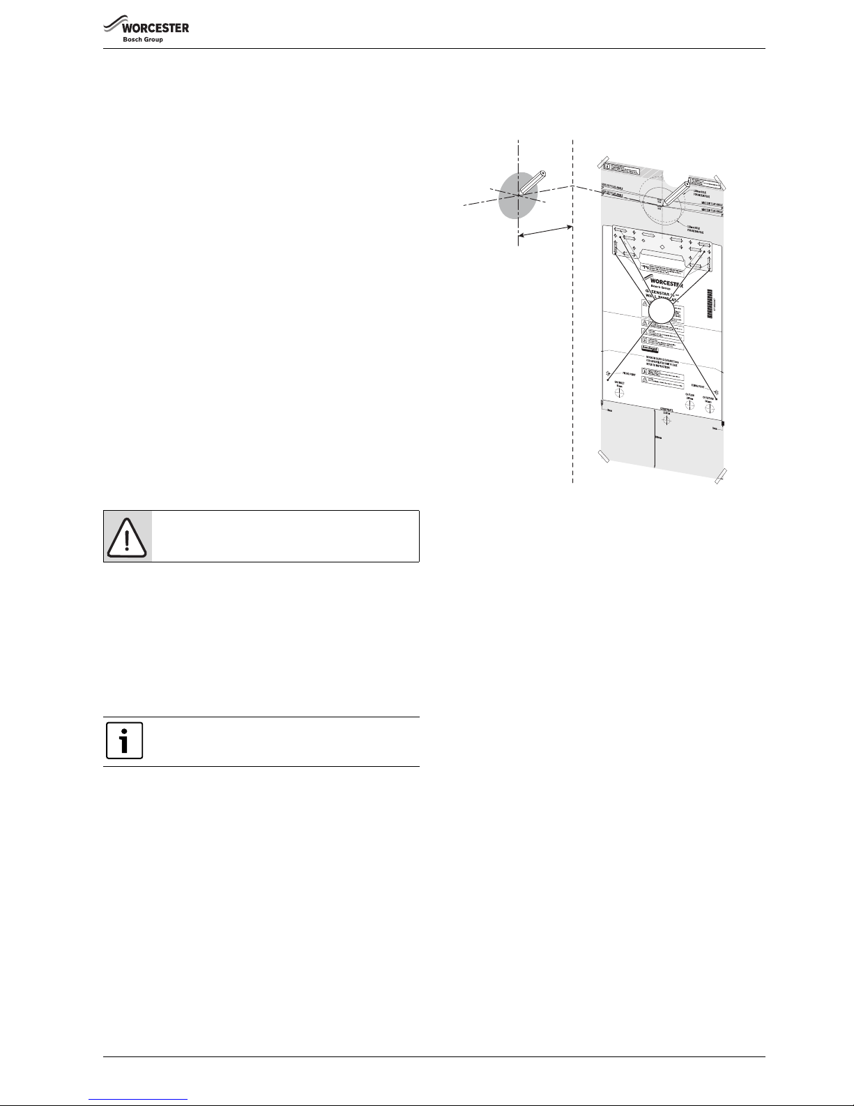
▶ The boiler template shows the relative positions of the flue and the top
and bottom fixing of the mounting frame.
1. Fix the template to the wall in the desired position.
2. Drill four holes for the wall mounting frame through the template.
Drill two holes for the bottom fixing screws.
REAR FLUE OUTLET
▶ The drawing opposite shows the boiler template with the flue centre
lines of both the 100mm and 125mm flue systems.
3. Mark centre line of flue to be used (3); the external diameter of the
hole can also be marked if required.
▶ If a 100mm diameter flue is to be used, a 125mm diameter hole is
required. However, if using the weather sealing collar by pushing it
through from inside the property, then a 150 mm diameter hole is
required to accommodate this.
▶ The flue turret of the 100mm flue has an in-built 3° angle.
▶ If extensions are to be added then the complete flue must rise at an
angle of 3°.
▶ The 125mm diameter flue system will require the flue to rise at an
angle of 3°.
▶ Drill hole using a core drill or similar.
SIDE OUTLET:
4. Mark from the centre line of th e wall template to the wall which the flue
will pass through (4).
▶ Allow for a rise of 52mm per metre length of flue, to give a 3 ° angle.
▶ Clear any debris from the site.
Fig. 26 Marking the flue position
WARNING: BEFORE DRILLING, ENSURE THAT THERE
ARE NO PIPES, ELECTRICAL CABLES, DAMP PROOF
COURSES OR OTHER HAZARDS.
The template has been sized to allow for minimum
clearances of 5mm sides, 200mm base and 30mm
above a 100mm diameter flue elbow.
4.
1.
3.
127 mm
2.
Page 24
INSTALLATION
Greenstar Ri
ErP
- 6 720 813 283 (2015/07)24
5.3 OUTER CASE REMOVAL
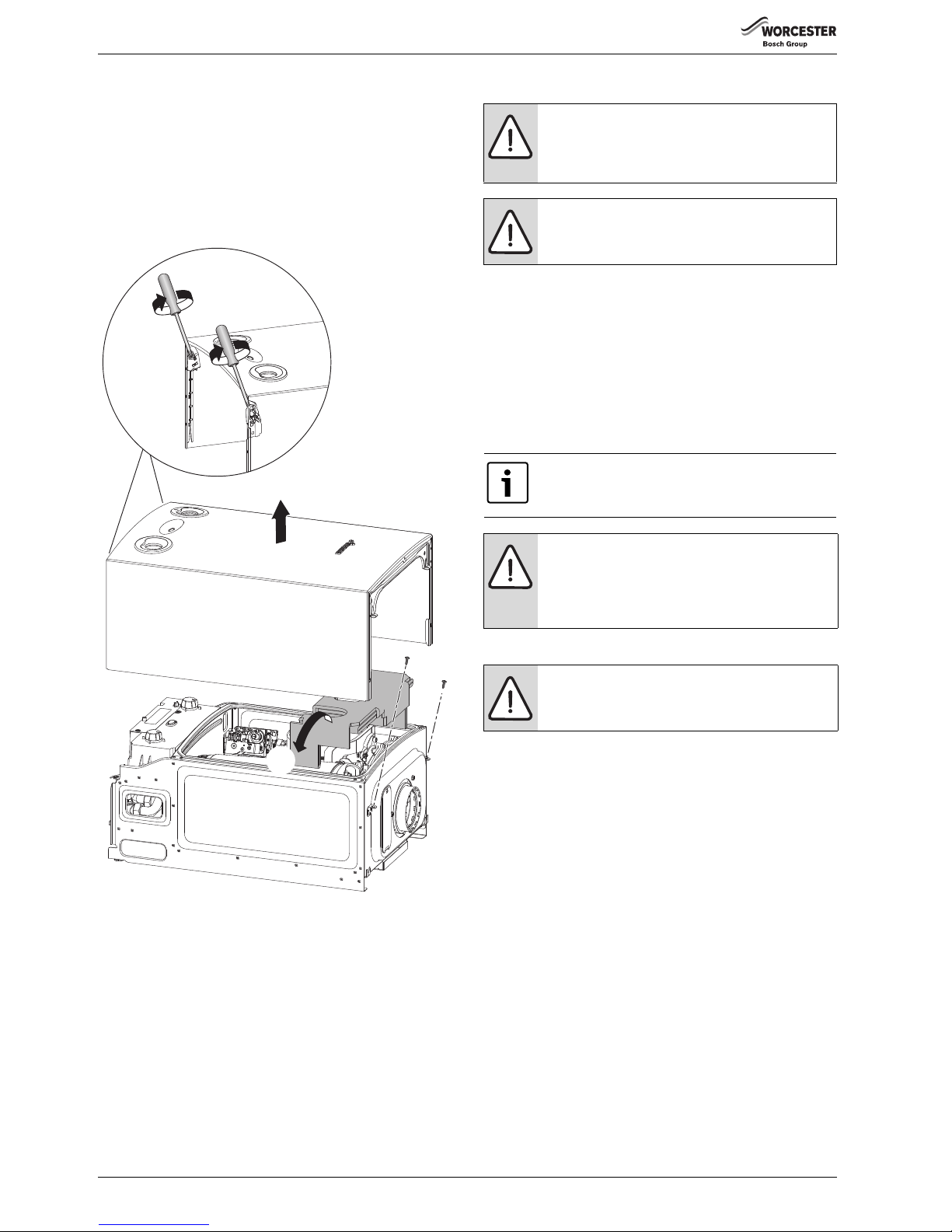
1. Undo the two captive screws securing boiler casing at the bottom of
the appliance.
2. Undo the two screws securing boiler casing at the top of the
appliance.
3. Pull case upwards.
4. Remove cardboard packing piece from appliance.
With the outer case removed the appliance is suitable for a one man lift
(<25kg).
Fig. 27 Case removal
5.4 BOILER CONNECTION
GAS AND WATER CONNECTIONS:
▶ Remove wall mounting template and secure the wall mounting frame
to the wall with the appropriate fittings for the boiler weight and wall
type.
▶ If there is greater than 600mm clearance below the appliance it is
possible to fit the flow and return pipes, supplied, with the boiler
installed on the wall.
▶ If clearance is less than 600mm below the appliance it may be
necessary to fit the flow and return pipes before hanging the
appliance.
System pipes may be run vertically up behind the boiler or below it.
6720804514-02.1Wo
2.
3.
4.
1.
CAUTION:
▶ ISOLATE THE MAINS GAS SUPPLY BEFORE
STARTING ANY WORK AND OBSERVE ALL RELEVANT
SAFETY PRECAUTIONS.
WARNING:
▶ Caps fitted to pipes must be removed before hanging
the boiler
The copper pipes supplied with the boiler are not to used
for the gas supply.
These copper pipes are for water only.
NOTICE:
▶ Lift the boiler using the handling holes at either side of
the frame.
Do not lift the boiler by the air gas manifold or control
box.
NOTICE:
▶ If pipes require reducing in length this is best done
before they are fitted to the boiler.
Page 25
INSTALLATION
Greenstar Ri
ErP
- 6 720 813 283 (2015/07) 25
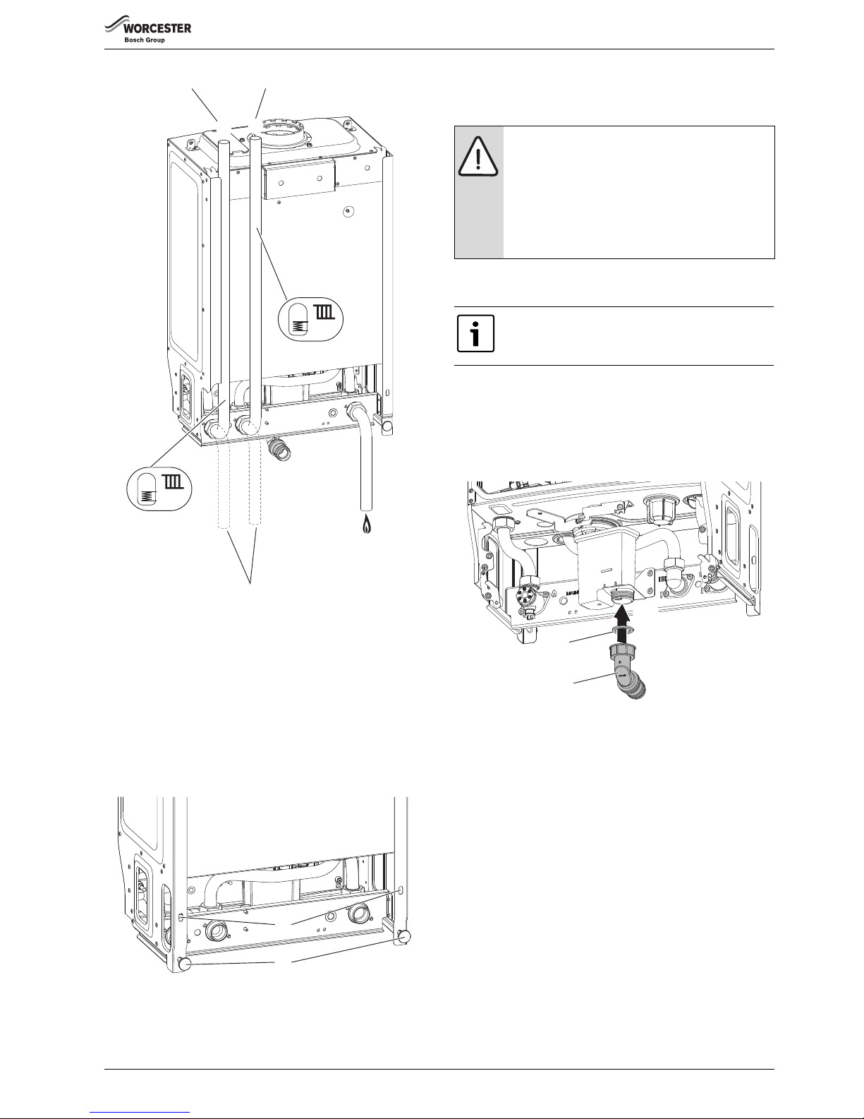
Fig. 28 Plumbing manifold
[1] Gas inlet (22mm)
[2] Condensate
[3] Flow (22mm)
[4] Return (22mm)
▶ Lift the boiler onto the wall plate.
▶ Level vertically using the feet (1) at the bottom rear of the boiler
casing.
▶ Fit retaining screws through the holes (2) in the boiler frame to secure
the boiler.
▶ Make connections to the heating system pipes.
Fig. 29 Levelling and securing detail
5.4.1 CONDENSATE CONNECTION
Never terminate or discharge into any open source, includi ng; sink, bath,
shower, bidet, toilet etc.
Figure 31 gives the pipe work dimensions with respect to the mounting
surface.
A sealing washer (1) and 22mm adaptor (2) are supplied in the fitting
pack
1. Fit washer (1) inside the plastic nut and attach firmly to the
connection on the syphon.
2. Connect the condensate disposal pipe work to the elbow (2), refer to
figure 31 and insert the condensate pipe 25mm into the elbow.
Fig. 30 Condensate connections
1
2
4
3
3
4
6720644744-13.1Wo
Pipes in alternative position
Return Flow
1
2
6720644744-56.1Wo
NOTICE: Condensate disposal
▶ Follow the recommendations given in section 4.4
“Condensate pipe work” for all condensate disposal
installation.
▶ Ensure that the condensate pipe work falls at least
50mm per metre towards the outlet.
▶ * Do not use solvents, adhesive or lubricant when
pushing the pipe onto the rubber connector.
When using the pre-formed water pipes provided with
the boiler, offset the water pipes connecting to them by
5mm to enable pipe clamps to be fitted.
6720644744-22.1Wo
1.
2.
1
2
*
Page 26
INSTALLATION
Greenstar Ri
ErP
- 6 720 813 283 (2015/07)26
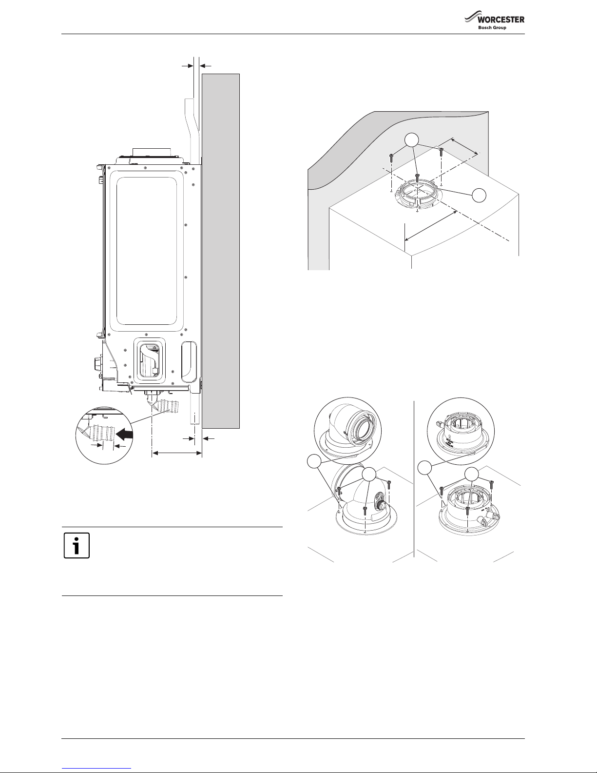
Fig. 31 Pipe work dimensions
5.5 Flue turret/adaptor installation
The flue turret/adaptor for the appliance is secured using three retaining
screws (figure 32, item [1]) which come in position on the appliance.
Refer to figures 32 & 33.
▶ Remove the three inner flue tube retaining screws [1].
The inner tube will be held in place in the appliance.
▶ Check the appliance flue seal [2] is correctly seated and apply
silicone grease.
Fig. 32 Flue turret centre
[D] 127mm
[W] 195mm
▶ Align the flue turret/vertical adaptor to the appliance flue outlet with
flat facing [3] to the rear of the appliance.
The flue turret/adaptor should be pushed straight down, on to the
appliance.
▶ The three inner flue tube retaining screws [1] are, re-used for the flue
turret and replacement retaining screws [4] supplied with the
adaptor kit are used to secure turret/adaptor to the appliance.
Fig. 33 Flue turret/adaptor connection
Additional notes and reminders:
• Ensure that all cut lengths are square and free from burrs.
• Ensure that the flue and seals are not damaged.
• The flue is sealed when assembled correctly, the components are
pushed fully home and secured.
• The flue is set at an angle of 3° or 52mm per metre length.
• Support the flue at approximately one metre intervals and at a
change of direction, use suitable brackets and fittings
(flue bracket 100mm part number: 7 716 191 177,
flue brackets 100mm x 6 part number: 7 716 191 178,
flue bracket 125mm part number: 7 716 191 179)
To ease assembly of flue components, apply silicone
lubricant to sealing surfaces.
Refer to the manual supplied with the flue kit for
complete installation instructions.
For plume management effective lengths and the
effective flue lengths, refer to details in section 4.8.
5mm
18mm
125mm
6720644744-19.1Wo
WALL
25mm
6720806944-84.1Wo
W
al
l
W
D
1
2
6720806944-85.1Wo
3
1
3
4
Page 27
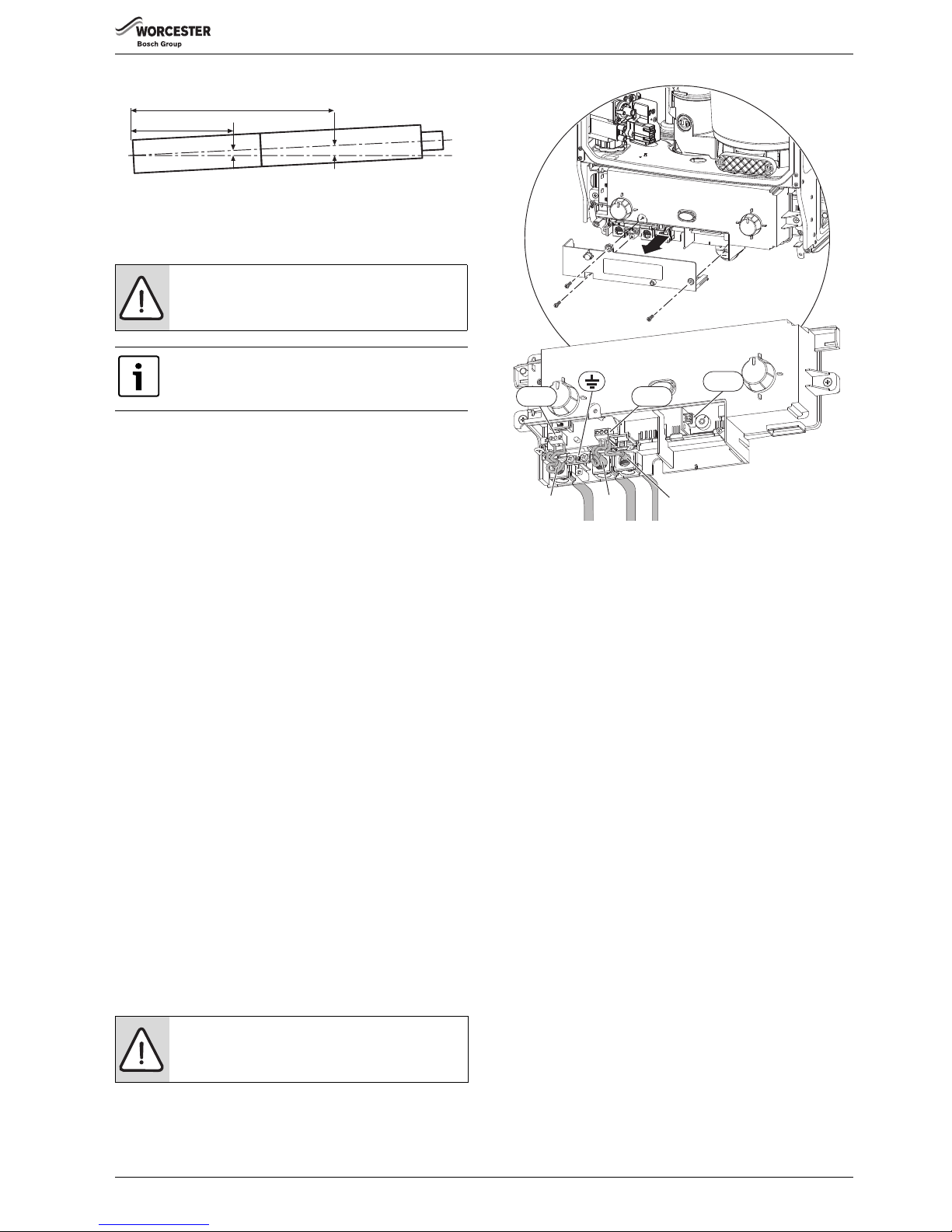
INSTALLATION
Greenstar Ri
ErP
- 6 720 813 283 (2015/07) 27
Fig. 34 Slope for condensate disposal
5.6 ELECTRICAL CONNECTIONS
▶ The mains supply to the boiler and system wiring centre must be
common, and through either a fused double pole isolator or a fused
three pin plug and unswitched socket.
▶ The isolator/socket, where practicable, should be situated next to the
boiler.
▶ The isolator must have a contact separation of 3mm minimum in both
poles.
▶ Any system connected to the boiler must not have a separate
electrical supply.
▶ External fuse rating 3A.
ACCESS TO ELECTRICAL CONTROL PANEL:
▶ Remove boiler casing to access control panel.
1. Unscrew the three screws in the control panel.
2. Remove the connections cover.
▶ Unclip cable clamp.
▶ Cut off the tapered cable entry to fit cable diameter required.
▶ Turn cable retaining screw anti-clockwise
▶ Run cable through the hole in t he m ain cro ssb ar marked “mains cable”
and through the cable clamp, ensure there is ample cable to reach the
connectors.
▶ Turn cable clamping screw clockwise to secure cable and replace
clamp into control panel.
3. Mains power 230v connection (ST1):
– Separate wires from cable end and strip to 6mm
– Connect LIVE wire to terminal (L)
– Connect NEUTRAL wire to the terminal (N)
– Connect EARTH wire to earth bracket
4. External Pump (ST2): Max power 90 W
– Connect NEUTRAL wire to terminal (Np)
– Connect LIVE wire to terminal (Lp)
– Connect EARTH wire to earth bracket
5. Boiler Demand (from external wiring centre) (ST2):
– Connect SWITCHED LIVE wire to terminal (LR).
Fig. 35 Wiring detail
NEW COMPLETE SYSTEM INSTALLATIONS
If a new complete heating system is installed in a new build property or it
is a first time installation in an existing property, the heating systems
must conform to current building regulations Part L1a.
The exception to this are single storey, open plan dwellings where the
liv ing are a is mor e than 7 0% of th e total usable floor area. Then this type
of dwelling can be controlled as one zone.
An alternative would be individual electronically controlled TRVs.
For dwellings with a floor area over 150m
2
, separate time and
temperature control for each zone is required. All radiators must have
TRVs fitted in all rooms except bathrooms and rooms with thermostats.
EXISTING INSTALLATIONS
For boiler replacements on an existing system, it is not nec essary to zone
the upstairs and downstairs differently, compliance with the zone
requirements can be achieved by a single room thermostat or
programmable room thermostat.
While the system is drained down, TRVs must be fitted to all rooms
except the bathrooms and the room with the thermostat.
CAUTION: Isolate the mains electrical supply before
starting any work and observe all relevant safety
precautions.
The boiler is already wired with a mains supply cable.
A spare strain relief block is supplied in case the prewired cable is replaced.1
NOTICE: SYSTEM PUMP
▶ THE SYSTEM PUMP MUST BE CONNECTED TO THE
APPLIANCE FOR THE PUMP OVER-RUN FUNCTION.
6720644842-10.1Wo
2m
1m
52mm
104mm
1.
2.
6720644744-25.1Wo
ST1 ST2
3. 4. 5.
ST7
Page 28
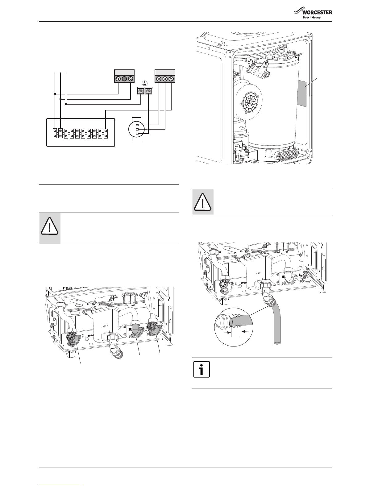
COMMISSIONING
Greenstar Ri
ErP
- 6 720 813 283 (2015/07)28
EXTERNAL WIRING CENTRE
System components wired into terminal strip in accordance with system
manufacturers instructions.
Fig. 36 External wiring centre
Refit electric control panel covers:
▶ Refit panel and secure with screws.
6 COMMISSIONING
6.1 PRE-COMMISSIONING CHECKS
▶ Check that the gas service pipe and water pipes are connected to the
correct position on the manifold.
1. Gas inlet (22mm)
2. Flow (22mm)
3. Return (22mm)
Fig. 37
▶ Check the gas type specified on the identification plate (1) matches
that of the gas supply.
Fig. 38 Data plate location
▶ Turn on the main gas supply, check the gas pipe work, connections
and rectify any leaks.
▶ Check that the condensate pipe has been connected to the syphon.
▶ Ensure that the condensate pipe has been inserted at least 25mm into
the elbow
Fig. 39 Condensate connection
WARNING: ELECTRIC SHOCK
▶ ISOLATE THE MAINS SUPPLIES BEFORE STARTING
ANY WORK AND OBSERVE ALL RELEVANT SAFETY
PRECAUTIONS
NE SWL
Wiring Centre/Junction Box
230V
MAINS SUPPLY
N
blue
brown
green/yellow
EL
NP LRLP
N
L
ST1 ST2
6720644744-26.1Wo
*
External Pump
90W max
L
E
N
1
2
3
NOTICE: Do not use solvents, adhesive or lubricant
when pushing the pipe onto the rubber connector.
If the boiler is not to be commissioned immediately then,
after successfully completing all of the checks and any
rectification work, shut off the gas and water supply and
electrically isolate the boiler.
1
6720804530-11.1Wo
6720644744-29.1Wo
25mm
Page 29
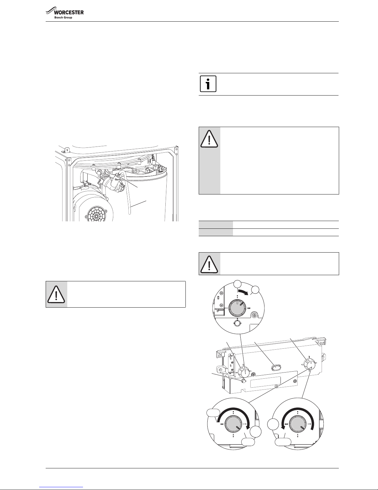
COMMISSIONING
Greenstar Ri
ErP
- 6 720 813 283 (2015/07) 29
6.2 FILLING THE SYSTEM
Open vented systems:
▶ Ensure all system and boiler drain points are closed.
▶ Open all radiator valves.
▶ Turn on the water supply to the system header tank and allow the
system to fill.
Sealed systems:
▶ Fill the system via a WRAS approved filling loop to 1 bar then turn the
valve anti-clockwise to close.
Opened vented and sealed systems:
▶ Vent (1) any air from the boiler heat exchanger using a suitable
container to collect any water. Ensure tube outlet (2) is directed away
from the fan or any other electrical component to prevent any water
damage. Also place a suitable cover over the fan to prevent any
spillage of water on to electrical connections. Ensure the cover is
removed after venting.
Fig. 40 Venting
▶ Vent all radiators and the primary side of the hot water cylinder,
tighten when completed and check the system and correct any leaks.
Sealed systems only:
▶ If required increase system pressure back to 1 bar.
▶ Isolate and remove filling loop connection to system.
6.3 WATER TREATMENT
It is possible to have an ion exchange water softener fitted to the cold
water system of the property. However, the boiler requires an untreated
cold water connection taken from the mains supply, before the water
softener, to the primary water filling point of the heating system.
Alternatively there are water softening/treatment devices that do not
adjust or alter the pH levels of the water. With these devices it may not
be necessary to provide an untreated water by-pass to the primary water
filling point of the heat system.
ENSURE THAT THE SYSTEM HAS BEEN CLEANED AS ON PAGE 11 OF
THESE INSTRUCTIONS.
FLUSHING (Central Heating):
▶ Switch off the boiler.
▶ Open all drain cocks and drain the system while the appliance is hot.
▶ Close drain cocks and add a suitable flushing agent at the correct
strength for the system condition in accordance with the
manufacturer's instructions.
▶ Run the boiler/system at normal operating temperature for the time
stated by the manufacturer of the flushing agent.
▶ Drain and thoroughly flush the system to remove the flushing agent
and debris.
INHIBITOR (Central Heating):
▶ Check drain cocks are closed and all radiator valves are open before
adding a suitable inhibitor compatible with aluminium (or combined
inhibitor/anti-freeze if the system is exposed to freezing conditions)
to the heating system water in accordance with the manufacturers
instructions.
▶ Fill system as described in section 6.2 opposite.
▶ Set all controls to maximum.
▶ Record the date when the inhibitor was added to the system on the
warrantee card.
WATER TREATMENT PRODUCTS
Suitable water treatment products can be obtain from the following
manufacturers:
6.4 STARTING THE APPLIANCE
Fig. 41 Boiler controls
NOTICE:
▶ ARTIFICIALLY SOFTENED WATER MUST NOT BE
USED TO FILL THE CENTRAL HEATING SYSTEM.
6720804530-12.1Wo
1
2
The pH value of the system water must be less than 8 or
the appliance warrantee will be invalidated.
NOTICE:
▶ The concentration of inhibitor in the system should be
checked every 12 months or sooner if system content
is lost.
▶ Normally the addition of sealing agents to the system
water is not permitted as this can cause problems
with deposits left in the heat exchanger.
▶ In cases where all attempts to find a micro leak have
failed, Worcester, Bosch Group supports the use of
Fernox F4 leak sealer.
FERNOX 0870 601 5000 or www.fernox.com
SENTINEL 0800 389 4670 or www.sentinel-solutions.net
CAUTION: RUNNING THE APPLIANCE
▶ Never run the appliance when the appliance/system is
empty or partially filled.
1
2
3
4
1.
0
1
1
0
MIN
RESET
MAX
max
min
2.
MIN
RESET
MAX
reset
3.
6720644744-30.1Wo
Page 30
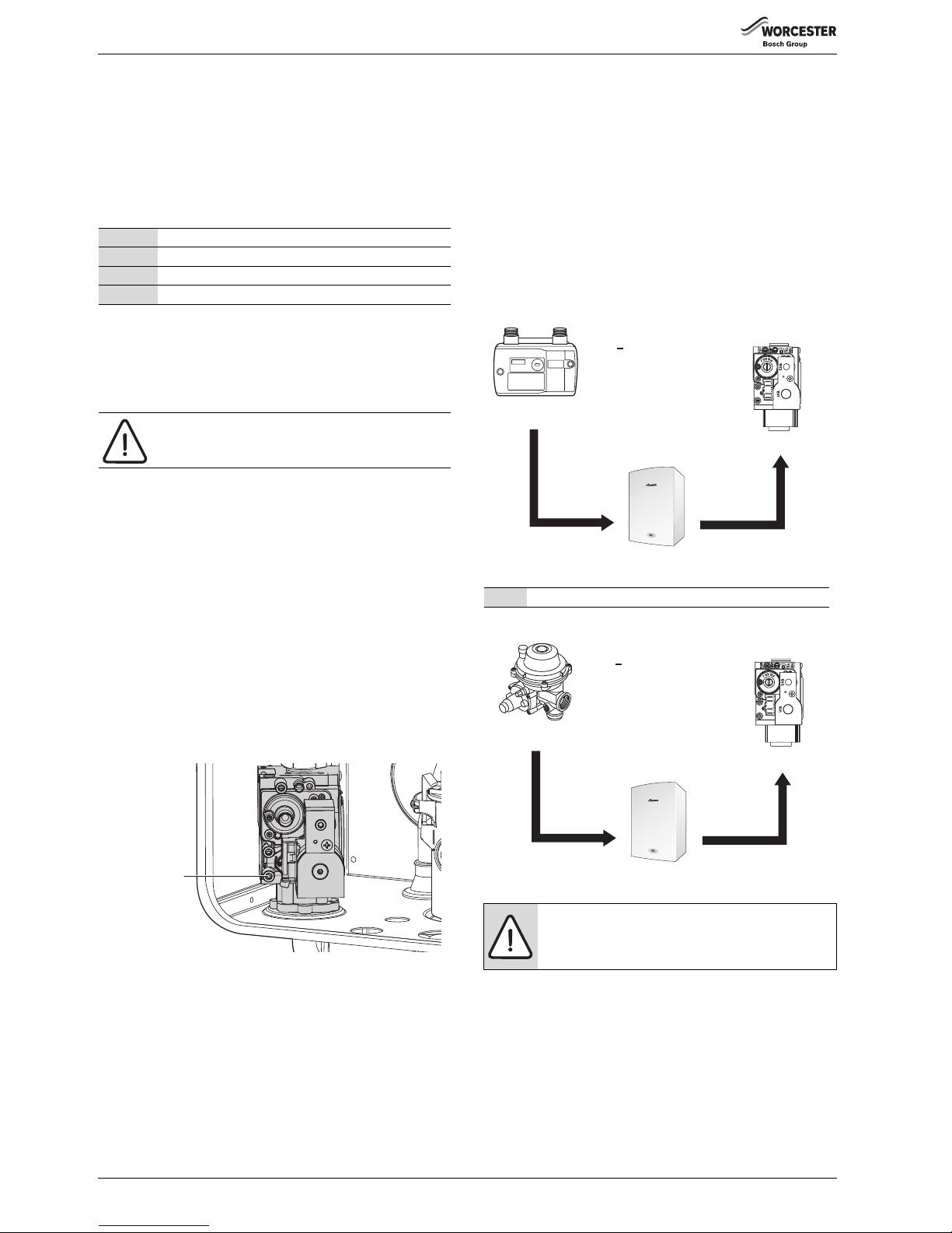
COMMISSIONING
Greenstar Ri
ErP
- 6 720 813 283 (2015/07)30
Switching the appliance ON/OFF:
▶ Turn on mains power, the power ON indicator (2) illuminates BLUE.
▶ Turn on any external controls
▶ Set the thermostatic radiator controls to maximum temperature
▶ Set the clock/programmer to continuously ON and the room
thermostat to maximum temperature
1. Turn Power ON/OFF knob (1) from 0 (OFF position) to I (ON
position), after two seconds the Power ON indicator (2) illuminates.
2. Turn the boiler CH temperature control (3) to maximum. The burner
on indicator (4) illuminates GREEN when the burner has lit.
▶ If the boiler fails to light and the boiler goes to flame lock-out, the
BLUE power indicator (2) will flash.
3. To reset the lockout turn the boiler thermostat control to minimum,
then passed minimum where the control knob will click at reset
position, wait 5 seconds then turn to maximum. The boiler will be
reset.
6.5 COMMISSIONING
Having checked:
▶ That the boiler has been installed in accordance with the installation
instructions.
▶ The integrity of the flue system and flue seals, as described in
section 7.3 of this manual.
▶ The integrity of the boiler combustion circuit and relevant seals.
6.5.1 CHECKING THE GAS INLET PRESSURE
The inlet pressure to the appliance must be checked using the following
procedure:
MEASURING THE INLET PRESSURE
Fig. 42 Inlet pressure test point
▶ Close gas isolation valve.
▶ Slacken the screw in the inlet pressure test point (1) and connect a
manometer.
▶ Open gas isolation valve.
▶ Measure the pressure with the boiler running at maximum.
– Refer to section 7.4 to set the boiler to maximum output.
– The boiler will stay at maximum for 15 minutes.
– Return the boiler to normal after the checks.
▶ Check the gas supply working pressure at the gas valve conforms to
values shown in Fig. 43 or Fig. 44 .
GAS PRESSURE WITHIN THE SYSTEM
Refer to the figures below for natural gas or L.P.G gas pressures.
The pressure at the boiler must not be less than the pressure read at the
meter minus:
•1mbar for Natural Gas
• 2.5mbar for L.P.G.
The pressure drop from the meter to the gas valve must not be more
than:
•2.5mbar for Natural Gas
• 4mbar for L.P.G.
If the pressure drops are greater than shown below, then this would
indicate a problem with the pipe work or connections within the system.
Fig. 43 Natural gas pressures
Fig. 44 L.P.G. pressures
1Power ON/OFF knob
2 Power ON and fault indicator (Blue)
3 Central heating temperature control
4 Burner indicator (Green)
Table 28 Control panel legend
NOTICE: RESET
▶ Do not press the blue power indicator to reset the
boiler.
6720643895-53.1Wo
1
Equal to or less than .....
NOTICE:
Do not continue commissioning until the correct gas
pressure is achieved.
Meter
Boiler inlet
Gas Control
valve
19 - 23 mbar
18 - 22 mbar
16.5 - 20.5 mbar
1 mbar
drop
1.5 mbar
drop
Natural Gas
< 2.5mbar
difference
6720644744-44.2Wo
Gas Control
valve
L.P.G.
< 4.0mbar
difference
Regulator
Boiler inlet
32 - 45 mbar
29.5 - 42.5 mbar
28 - 41 mbar
2.5 mbar
drop
1.5 mbar
drop
6720644744-45.2Wo
Page 31
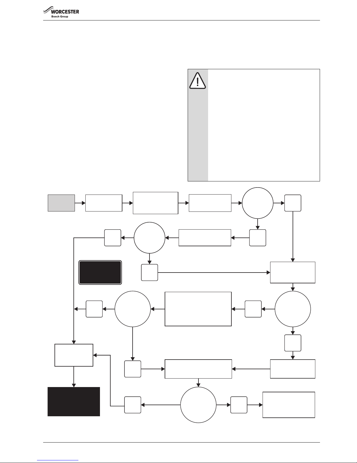
COMMISSIONING
Greenstar Ri
ErP
- 6 720 813 283 (2015/07) 31
6.5.2 CHECKING THE GAS RATE
▶ The gas rate should be measured at the gas meter after 10 minutes
operation at maximum.
See technical data section at the front of this manual.
▶ Where a gas meter is not available (e.g. L.P.G.) the CO/CO
2
must be
checked to the units shown in the setting of the air/gas ratio, refer to
section 7.6.
▶ If pressure and gas rate are satisfactory press the service button and
the boiler will return to normal operation.
– If left in the service mode the control will return to normal operation
after 15 minutes.
▶ Close the gas isolation valve.
▶ Remove the manometer.
▶ Re-seal the screw in the gas inlet pressure test point.
▶ Open the gas isolation valve.
▶ Ensure that there are no gas leaks.
▶ Replace the outer case.
6.6 CO AND COMBUSTION CHECKS
The following combustion and flue integrity checks are mandatory from
April 2014 and these values must be recorded on the Benchmark check
list, at the back of this manual.
Once the gas rate and pressure have been confirmed as acceptable then
the CO and combustion checks can be undertaken.
The flow chart is given for guidance, the details of the checks are given in
the following sections:
• Checking flue integrity, refer to section 7.3, page 34
• Flue gas analysis, refer to section 7.5, page 35
Fig. 45 Combustion check flow chart
NOTICE: BEFORE CO AND COMBUSTION CHECKS:
▶ Refer to section 6.5.1 and 6.5.2 to verify gas type,
gas inlet pressure, and gas rate.
Visually check the integrity of the whole flue system
and confirm that all the components are correctly
assembled, fixed and supported.
▶ The flue gas analyser must be the correct type as
specified in BS 7967. Before use the analyser must
have been calibrated as specified by the
manufacturer.
The installer must be competent in the use of the
analyser.
Check and zero the analyser in fresh air as specified
by the manufacturer.
▶ The gas valve is factory set and must not be adjusted
during commissioning if found to be out of tolerance,
please contact the Worcester, Bosch Group help line
0330 123 3366.
Yes
No
Yes
Yes
Set boiler to
minimum rate.
Check all seals around the
burner, internal flue seals,
and case seals.
Rectify where necessary.
Turn off boiler and
call Worcester, Bosch
Group help line.
0330 123 3366
No
Boiler is operating
satisfactorily.
No further action
is required.
No
No
Verify flue integrity
O2 ≥ 20.6%
CO
2
< 0.2%
O2 ≥ 20.6%
CO
2
< 0.2%
No
Yes
Check CO and
combustion ratio
at maximum rate
Check CO and combustion
ratio at minimum rate
CO < 350ppm
CO/CO
2
ratio
< 0.004
CO < 350ppm
CO/CO
2
ratio
< 0.004
CO < 350ppm
CO/CO
2
ratio
< 0.004
Flue integrity test
using analyser
Yes
Set boiler to
maximum rate.
START
HERE
6720809056-01.2Wo
Zero the analyser
in fresh air.
See notice above
Record values.
Do not adjust
the gas valve.
≥ =
greater than
or equal to
< =
less than
Page 32
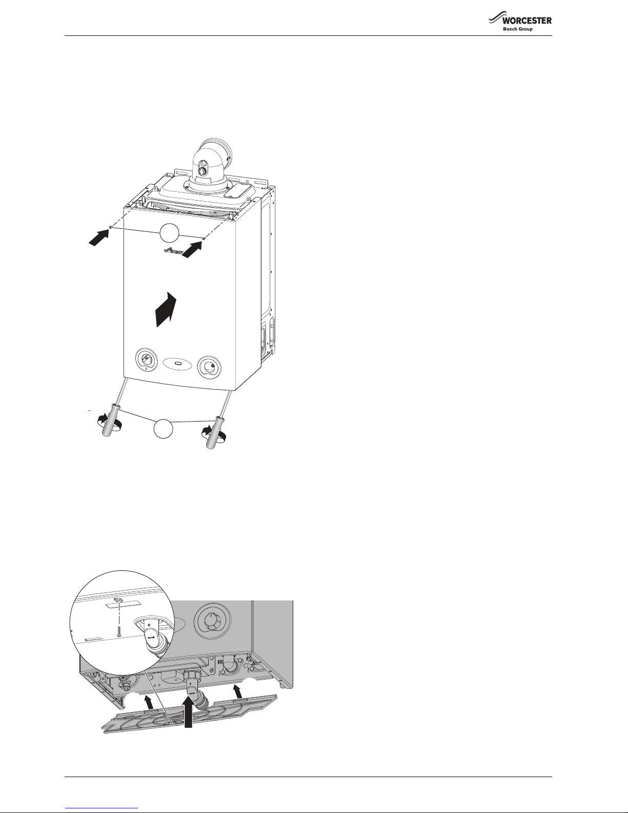
COMMISSIONING
Greenstar Ri
ErP
- 6 720 813 283 (2015/07)32
6.7 FINISHING COMMISSIONING
6.7.1 REPLACE THE OUTER CASE:
Replace outer casing making sure that the securing points are properly
located.
1. Replace top two screws.
2. Re-tighten bottom two screws.
Fig. 46 Replacing outer case
6.7.2 INSTALL THE BOTTOM PANEL
The cut out in the bottom panel fits easily over the syphon elbow and
outlet, however care should be taken not to disturb any sealed
components.
1. Hook the lip at the back of the bottom panel over the angled edge at
the base of the connections manifold.
2. Push up into position.
3. Secure in position the screw provided.
Fig. 47 Bottom panel
6.7.3 HAND OVER
▶ Open the fascia flap by hinging the flap downwards using the curved
hand hold in the centre of the flap.
▶ Set up the controls and show the customer how to operate all the
controls shown in the User Guide plus any external controls.
▶ Instruct the customer on:
– how to use the TRVs.
– how to reset the boiler.
▶ Show the customer the fault finding information in the User guide.
▶ Show the customer where the serial number/boiler information is
when they call in with a problem (Benchmark checklist at the rear of
the manual).
▶ Give the customer details of how to contact the installer/gas
emergency numbers.
▶ Show the customer how to safely isolate the boiler
▶ Advise the customer where they can find information on the
Worcester, Bosch Group website.
▶ Advise the customer that the varying external temperatures will affect
the output of the boiler.
▶ Ensure that the User Guide and Installation, Commissioning and
Service manual, with the Benchmark checklist and service record, is
left with the boiler or homeowner.
▶ If the appliance is unused and exposed to freezing conditions, shut off
all the mains supplies and drain the system and boiler, label
accordingly.
6.7.4 Appliance guarantee
This appliance has a guarantee against faulty materials or workmanship
for a period from the date of installation subject to the following terms
and conditions:
• During the period of this guarantee any components of the appliance
which are proven to be faulty or defective in manufacture will be
exchanged or repaired free of charge by Bosch Thermotechnology
Ltd.
• The householder may be asked to prove the date of installation, that
the appliance was correctly commissioned and, where appropriate,
the first year's service has been carried out to the satisfaction of
Bosch Thermotechnology Ltd., when requested. These should be
documented as a part of the Benchmark Checklist.
• The appliance has been used only for the normal domestic purposes
for which it was designed.
This guarantee does not affect your statutory rights.
Guarantee registration
Your Greenstar appliance carries a guarantee against faulty material or
manufacture subject to Terms and Conditions.
Guarantee Registration can be completed:
•On-line
– You can register on our website:
www.worcester-bosch.co.uk/guarantee
•By phone
– You can register by ringing 0330 123 2552
•By post
– Please send your completed form to:
Worcester, Bosch Group, Cotswold Way, Warndon, Worcester,
WR4 9SW.
To read the full Terms & Conditions please visit us on-line at
www.worcester-bosch.co.uk/guarantee.
Your statutory rights are not affected by the manufacturer’s guarantee.
6720644744-33.1Wo
1.
2.
6720644744-34.2Wo
1.
1.
2.
3.
Page 33
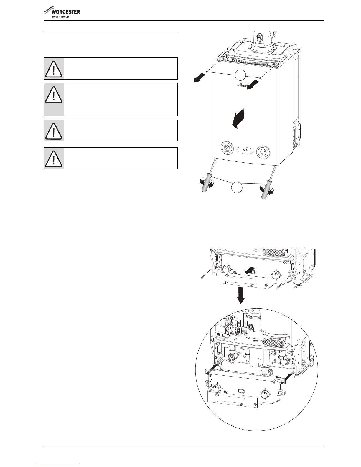
SERVICE AND SPARES
Greenstar Ri
ErP
- 6 720 813 283 (2015/07) 33
7 SERVICE AND SPARES
7.1 INSPECTION AND SERVICE
• To ensure the continued efficient operation of the appliance it must be
checked at regular intervals.
• T he frequency of servicing will depend upon the particular installation
conditions and usage however, an annual service is recommended.
• The extent of the service required by the appliance is determined by
the operating condition of the appliance when tested by fully qualified
engineers.
• The service interval record sheet at the rear of these instructions
must be completed after each service.
INSPECTION
1. Check that the terminal and the terminal guard, if fitted, are clear and
undamaged.
2. If the appliance is in a compartment or cupboard check that the
specified service space around the appliance is clear.
3. Check all the joints and connections in the system and remake any
that show signs of leakage.
Refill and re-pressurise if applicable as described in Commissioning,
section 6.2.
4. Operate the appliance and take note of any irregularities.
Refer to Fault Finding on page 48 for rectification procedures.
COMPONENT ACCESS
Removing outer case
1. Undo and remove two screws securing boiler casing at the top of the
appliance.
2. Undo but do not remove the two screws securing boiler casing at the
bottom of the appliance.
▶ Pull case forward and remove.
Fig. 48 Remove outer case
LOWERING THE BOILER CONTROLS TO THE SERVICE POSITION:
1. Remove two screws securing the control.
2. Pull the control forward.
3. Lower the control to align the slots at the top of the control with the
lugs on the boiler framework.
4. Hang control on two lugs on boiler framework.
Fig. 49 Control panel into service position
CAUTION: TURN OFF THE GAS SUPPLY AND ISOLATE
THE MAINS SUPPLIES BEFORE STARTING ANY WORK
AND OBSERVE ALL RELEVANT SAFETY PRECAUTIONS.
NOTICE: COMPONENTS.
▶ After replacement of any components always check
for gas tightness where relevant and carry out
functional checks as described in Commissioning.
Damaged O-rings or gaskets must be replaced.
NOTICE: Service work
▶ Service work must be carried out by a competent
engineer, such as Gas Safe registered personnel!
NOTICE: FLUE GAS ANALYSER
▶ Service work must not be attempted if a flue gas
analyser is not available.
6720644744-35.1Wo
1.
2.
6720644744-36.1Wo
1.
1.
2.
3.
4.
4.
Page 34
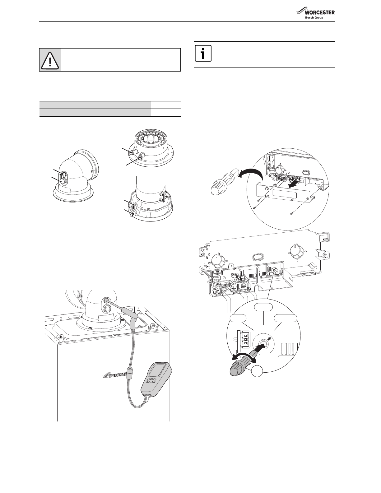
SERVICE AND SPARES
Greenstar Ri
ErP
- 6 720 813 283 (2015/07)34
7.2 CHECKING GAS INLET PRESSURE
Refer to section 6.5.1 for checking the gas inlet pressure
7.3 CHECKING FLUE INTEGRITY
The integrity of the flue system and performance of the boiler can be
checked via the flue turret sample points.
Fig. 50 Flue test points
▶ With the boiler case on and the boiler running at maximum.
▶ Insert the analyser probe into the air intake test point.
▶ Allow the readings to stabilise and check that:
–O
2
is equal to, or greater than 20.6%
–CO
2
is less than 0.2%
▶ If the readings are outside these limits then this indicates that there is
a problem with the flue system or combustion circuit, e.g. missing or
dislodged seals.
Fig. 51 Flue integrity test
7.4 FAN PRESSURE TEST
SETTING THE BOILER TO MAXIMUM
1. Remove the three screws retaining the control cover.
2. Remove the control cover.
3. Remove the plastic tool clipped inside the cover.
4. Insert the tool into the switch.
5. Using the tool set the mode switch to maximum output.
Ensure the boiler is powered up and there is a demand from the external
controls.
The power indicator will flash and the boiler will stay in this mode for 15
minutes if no further change is made to the switch.
Fig. 52 Setting the boiler to maximum
NOTICE:
▶ Do not continue with the other checks if the correct
gas inlet pressure can not be achieved.
Flue gas sample point 1
Air inlet sample point 2
Table 29 Key to figure 50
2
1
2
2
1
1
6720643895-67.1Wo
6720644744-37.1Wo
This test is to determine if the heat cell requires
cleaning/attention.
1.
2.
6720644744-31.1Wo
3.
MAX
MIN
NORM
MAX
MIN
NORM
4.
5.
Page 35
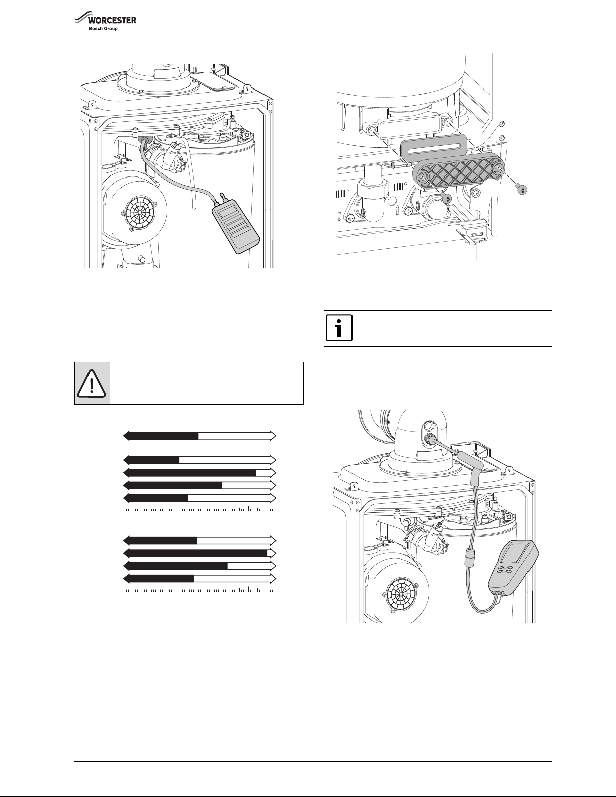
SERVICE AND SPARES
Greenstar Ri
ErP
- 6 720 813 283 (2015/07) 35
FAN PRESSURE TEST
Fig. 53 Fan pressure test
▶ Remove the cover and connect a digital manometer to the fan
pressure test point.
▶ The pressure will read negative, refer to the chart in figure 54.
▶ After measurement replace test point cover and return mode switch
to normal.
▶ Replace the control cover.
▶Replace outer case.
Fig. 54 Fan pressure readings
If the boiler fails the fan pressure test then before adjusting the air/gas
ratio, try the following:
▶ Check the syphon is not blocked.
1. Remove the screws securing the sump cover.
2. Remove the sump cover.
3. Clean the sump with a suitable brush.
▶ Check the exhaust path and flue for restriction.
▶ Re-check the Fan Pressure readings
Fig. 55 Sump access
7.5 FLUE GAS ANALYSIS
COMBUSTION TEST:
▶ Connect the flue gas analyser to the flue gas sampling point as shown
in the figure below.
▶ Run the boiler at maximum output for at least 10 minutes.
▶Check the CO/CO
2
readings against the information in table 30 CO/
CO
2
settings on page 36.
Fig. 56
If the boiler fails the combustion test, check:
1. Air intake for restriction
2. Diaphragm in the fan, for correct operation
3. Cleanliness of the heat cell, plus blockages in the condensate
disposal.
NOTICE:
The boiler must be run at maximum output for Fan
Pressure test and the Flue Gas analysis.
NG Boilers
0
-6
-5
-4
-3
-2-1
-8
-7
mbar
- 7.4
- 3.1
18 Ri:
24 Ri:
12 Ri:
15 Ri:
- 3.6
- 5.5
LPG Boilers
0
-6
-5
-4
-3
-2-1
-8
-7
mbar
FAN PRESSURE TEST
Clean the Heat Ex.
Heat Ex. ok
- 8.0
- 4.1
18 Ri:
24 Ri:
12 Ri:
15 Ri:
- 3.9
- 5.8
6720644744-39.1Wo
Ensure that the gas inlet pressure has been checked and
is satisfactory,
refer to section 6.5.1
6720644744-40.1Wo
1.
1.
2.
3.
6720804530-14.1Wo
Page 36
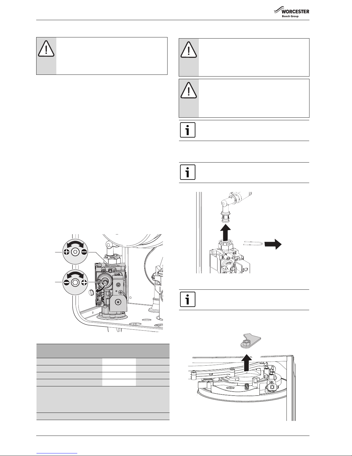
SERVICE AND SPARES
Greenstar Ri
ErP
- 6 720 813 283 (2015/07)36
7.6 SETTING THE AIR/GAS RATIO
7.6.1 SETTING THE CO/CO
2
▶ Refer to section 7.2 and ensure that the gas inlet pressure is correct
before continuing.
▶To adjust the CO/CO
2
it will be necessary to first operate the boiler at
maximum output.
▶ Refer to section 7.4 for setting the boiler to maximum and minimum
output.
▶ Refer to table 30 and check the CO/CO
2
at maximum. If required set
the maximum CO/CO
2
via adjuster (1) on the gas valve using a 2.5mm
Allen key.
▶ Check CO is less than 200ppm.
▶ Set the control to minimum.
▶ The boiler will go to minimum power.
▶Measure the CO/CO
2
and check against table 30.
If required set the minimum CO/CO2 via adjuster (2) on the gas valve
until the correct measurement is set:
– Remove dust cap with flat bladed screw driver.
– Using a 4mm Allen key adjust CO
2
.
– Replace the dust cap.
▶ Check that the CO is less than 200ppm.
▶ Return the boiler control to maximum and re-check the CO/CO
2
.
If correct, set the boiler control to normal “NORM”.
▶ Re-fit the control cover
▶ Re-fit boiler outer case.
Fig. 57 Gas valve adjustment
7.7 CLEANING THE HEAT EXCHANGER
▶ Isolate the power to the appliance and remove outer case and base
panel.
1. Refer to figure 58 and remove the clip from gas valve outlet.
2. Pull the gas outlet elbow free from the gas valve.
Fig. 58 Gas valve connection
▶ Remove electrical connector and earth wire from fan.
▶ Disconnect spark electrode and flame sensor connections.
1. Refer to figure 59 and undo the securing nut on the top of the heat
exchanger and remove the retaining plate assembly.
Fig. 59 Securing nut
NOTICE: THE SETTING OF THE GAS RATIO MUST BE
CARRIED OUT BY A COMPETENT PERSON. SETTING OF
THE GAS RATIO MUST NOT BE ATTEMPTED UNLESS
THE PERSON CARRYING OUT THE TEST IS EQUIPPED
WITH A COMBUSTION ANALYSER CONFORMING TO BS
7927 AND IS COMPETENT IN ITS USE.
CO/CO2 settings for Greenstar Ri
CO/CO2 should be measured after 10 minutes.
Gas type CO2 max. CO2 min.
Natural gas 12 Ri 9.65% 0.5 8.65% 0.5
Natural gas 15/18/24 Ri 9.8% 0.5 9.2% 0.5
L.P.G. 11.0% 0.5 10.5% 0.5
NOTE: When checking an existing appliance the tolerance is 0.5.
If checking after cleaning or component replacement or for adjustment
when the reading obtained is outside the tolerances given above, then
the tolerance is 0.2.
CO - less than 200 ppm (0.002 ratio)
Table 30 CO/CO2 settings
6720643895-66.1Wo
2
1
MAX
MIN
2.5 mm
4 mm
NOTICE: COMBUSTION TESTING
▶ Combustion testing must be carried out by a
competent person. Testing must not be attempted
unless the person carrying out the combustion check
is equipped with a Combustion Analyser conforming
to BS 7927 and is competent in its use.
NOTICE: CO/CO2 CHECKS
▶ If the joint between the Air/Gas manifold and heat
exchanger is disturbed, replace the sealing gasket.
▶ After completing the service of the appliance, the CO/
CO
2
must be checked and set to the limits shown in
“Setting the air/gas ratio” on page 36.
There is a special accessory kit available specifically
designed for cleaning the heat exchanger. If required
order 7 716 192 312.
If the plastic elbow can not be easily removed, undo the
nut to push the plastic elbow out of the fitting.
To prevent damage to the electrodes when removing the
air/gas manifold, disconnect the leads to the electrodes.
1.
2.
6720643895-72.1Wo
1.
6720643895-60.1Wo
Page 37
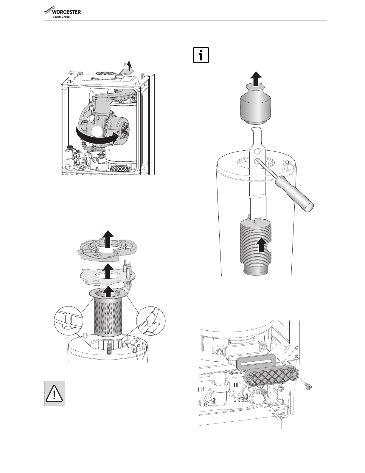
SERVICE AND SPARES
Greenstar Ri
ErP
- 6 720 813 283 (2015/07) 37
1. Refer to figure 60 and rotate fan and air/gas manifold assembly
around the top of the heat exchanger until it stops at the lug.
▶ Lift up assembly and remove from boiler.
2. Remove the cover panel by removing retaining screw.
Fig. 60 Rotate air/gas manifold
BURNER REMOVAL
Refer to figure 61
1. Remove clamping plate.
2. Remove spark/flame electrode assembly and seal from the top of the
heat exchanger.
3. Remove burner.
Fig. 61 Burner removal
Checking and cleaning the electrode assembly:
▶ Inspect the condition of the electrodes and ceramics, replace if
necessary.
▶ Use a plastic scouring pad to clean the electrodes.
BAFFLE REMOVAL
1. Refer to figure 62and remove top baffle.
2. Remove lower baffle.
Fig. 62 Baffle removal
ACCESS COVER REMOVAL
Refer to figure 63.
1. Remove the two pozi-drive screws
2. Remove the access cover
3. Remove the gasket.
Fig. 63 Access cover removal
NOTICE: Cleaning
▶ Do not use wire wool to clean the electrodes
1.
2.
1.
2.
3.
6720643895-61.1Wo
If the lower baffle is stuck, it may be necessary to use the
“Baffle removal tool” from the heat exchanger cleaning
kit - 7 716 192 312, as shown in figure 62.
6720643895-64.1Wo
1.
2.
6720644744-40.1Wo
1.
1.
2.
3.
Page 38
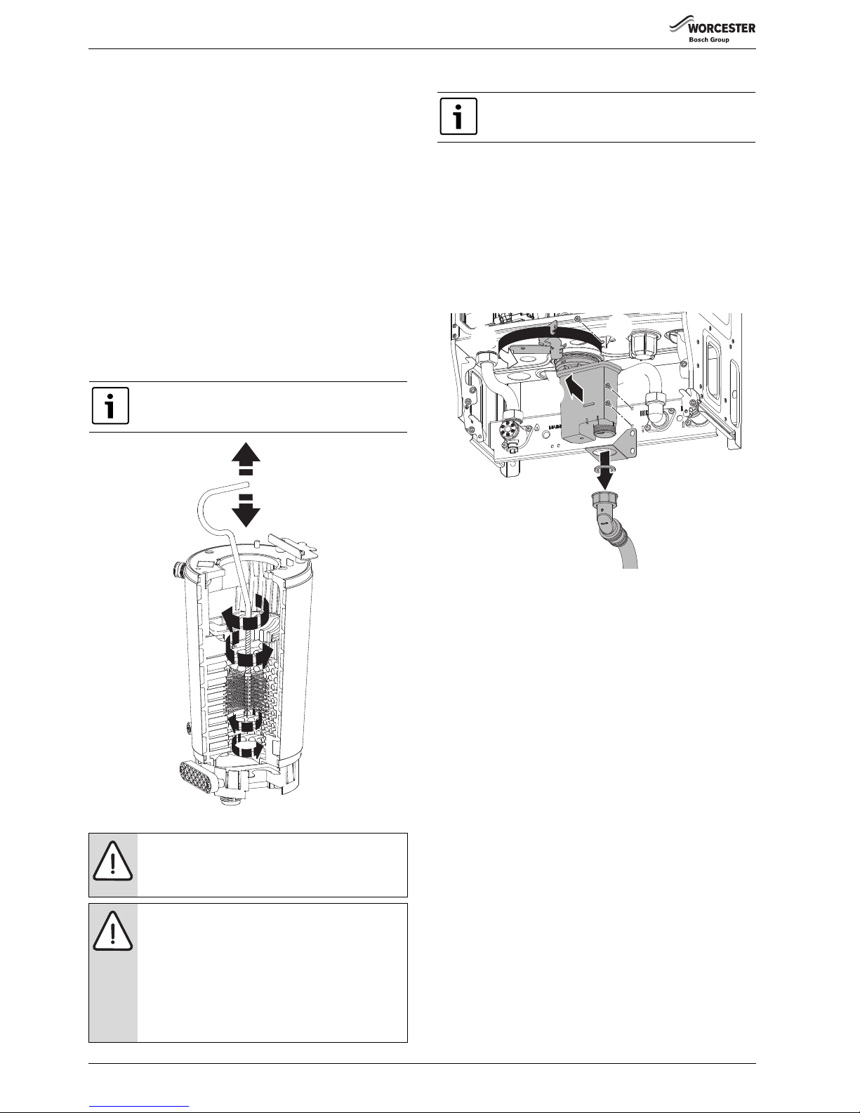
SERVICE AND SPARES
Greenstar Ri
ErP
- 6 720 813 283 (2015/07)38
CLEANING THE PRIMARY HEAT EXCHANGER
▶ Refer to figure 64 and access the heat exchanger flue ways by
inserting the cleaning brush (7 716 192 312) through the top access
hole in the casing, removal of panel shown in figure 60.
▶ Clean heat exchanger flue ways using the cleaning brush removing any
debris from the access point in the sump.
▶ Clean around the sealing surface on the sump.
▶ Replace the access cover.
▶ Using a suitable container to collect water from syphon connection at
the base of the boiler flush heat exchanger with water.
▶ Re-assemble ensuring that the lower baffle (2) and the top baffle (1)
are refitted correctly.
▶ Refer to figure 61 when re-fitting the burner to ensure that it fits
centrally within the heat exchanger and location tabs are situated in
location holes.
▶ Ensure that the seal is replaced with a new seal and ensure that the
seal is correctly fitted.
▶ Check the syphon unit is clean before refitting to boiler.
▶ Reassemble and check combustion as stated in “SETTING THE AIR/
GAS RATIO” section on page 36.
Fig. 64 Cleaning heat exchanger
7.7.1 SYPHON REMOVAL AND CLEANING
To release the syphon from the sump:
1. Undo the plastic nut on the bottom of the syphon and move the
condensate pipe away from the syphon.
2. Remove the two screws retaining the syphon bracket.
3. Remove the bracket.
4. Remove the screw and release the syphon retaining clamp
5. Swing the clamp completely to the left away from the syphon
6. Pull the syphon towards you and remove from the sump connection.
▶ Empty the contents of the syphon into a suitable container.
▶ Flush the syphon through with clean water
Fig. 65 Syphon removal
The heat exchanger does not need to be removed to
clean. The heat exchanger is shown removed from the
boiler to illustrate cleaning more clearly.
NOTICE: Heat exchanger baffles.
The baffles (1) and (2) must be refitted into the heat
exchanger in the order shown in figure 62. Failure to do
so may result in damage to the boiler.
NOTICE: CO/CO2 CHECKS
▶ If the joint between the Air/Gas manifold and heat
exchanger is disturbed, replace the sealing gasket.
▶ After completing the service of the appliance, the CO/
CO
2
must be checked and set to the limits shown in
“Setting the air/gas ratio” on page 36.
▶ When replacing the burner gasket ensure that the
clamping plate is fully tightened down to the heat
exchanger.
6720643895-65.1Wo
Remove the syphon assembly to clean.
6720644744-42.1Wo
1.
2.
3.
4.
5.
6.
Page 39

SERVICE AND SPARES
Greenstar Ri
ErP
- 6 720 813 283 (2015/07) 39
7.8 REPLACEMENT OF PARTS
7.8.1 REMOVING THE OUTER CASING
▶ Remove bottom tray by pressing the tabs (2) in, at the front underside
of the boiler.
▶ Lower the panel.
▶ Pull the panel forward, off the retaining ledge (1) at the back of the
boiler.
Fig. 66 Remove bottom panel
1. Undo the two screws securing the top of the boiler casing.
2. Undo the two screws securing the bottom of the boiler casing.
▶ Pull case forward and remove.
Fig. 67 Remove outer case
7.8.2 PRIMARY SENSOR (CH NTC)
Refer to figure 68 for removal.
1. Remove electrical connection by pulling upwards. Squeeze retaining
clip on plastic moulding of sensor and pull back and up until clear of
pocket in heat exchanger.
2. Pull forward to remove completely.
▶ Coat new sensor with heat conductive paste and replace.
7.8.3 OVERHEAT THERMOSTAT
Refer to figure 68 for removal.
▶ Remove two electrical connectors from thermostat.
3. Slacken and remove fixing screw and thermostat (3).
▶ When replacing ensure thermostat sits correctly on surface of the
casting with the left hand side of thermostat sitting up against the
shoulder.
Fig. 68 Primary sensor and overheat thermostat
CAUTION: TURN OFF THE GAS SUPPLY AND ISOLATE
THE MAINS SUPPLIES BEFORE STARTING ANY WORK
AND OBSERVE ALL RELEVANT SAFETY PRECAUTIONS.
NOTICE: REPLACEMENT OF COMPONENTS.
▶ After replacement of any components always check
for gas tightness where relevant and carry out
functional checks as described in Commissioning.
Damaged O-rings or gaskets must be replaced.
6720644744-34.1Wo
1.
1.
2.
2.
6720644744-35.1Wo
1.
2.
To gain access to the following components the outer
case has to be removed:
▶ Primary sensor
▶ Overheat thermostat
▶ Flue limit thermostat
It is essential that the mating surface of the thermostat is
coated with heat conductive paste.
6720804530-15.1Wo
1.
2.
3.
Page 40
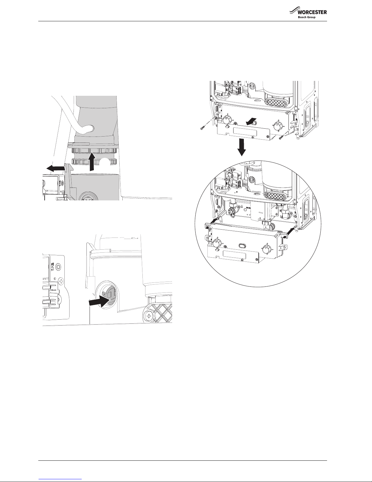
SERVICE AND SPARES
Greenstar Ri
ErP
- 6 720 813 283 (2015/07)40
7.8.4 FLUE OVERHEAT THERMOSTAT
(WITH GROMMET)
To remove and replace the thermostat either:
▶ Using a small terminal screwdriver, prise the thermostat and grommet
from the plastic housing.
Take care not to damage the plastic housing.
-or-
1. Release the flue connection from the sump.
2. Push the flue tube up.
Fig. 69 Lower exhaust section
▶ Remove electrical connections.
1. Push the flue limit thermostat in from the sump.
▶ Retrieve the thermostat from the sump well.
Fig. 70 Remove thermostat
To replace, push the thermostat and new grommet gently back into the
opening until contact with the locating ridge is felt.
7.8.5 LOWERING THE BOILER CONTROLS TO THE SERVICE
POSITION:
1. Remove two screws securing control.
2. Pull the control forward.
3. Lower the control to align the slots at the top of the control with the
lugs on the boiler framework.
4. Hang control on two lugs on boiler framework.
Fig. 71 Control panel into service position
6720644744-47.1Wo
2.
1.
6720643895-70.1Wo
1.
6720644744-36.1Wo
1.
1.
2.
3.
4.
4.
Page 41
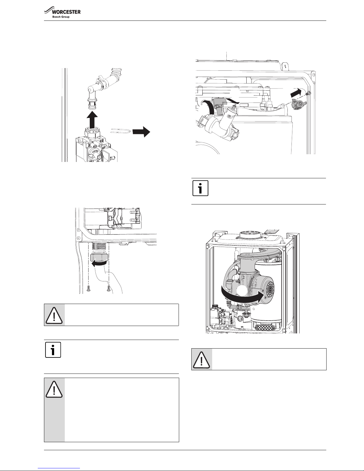
SERVICE AND SPARES
Greenstar Ri
ErP
- 6 720 813 283 (2015/07) 41
7.8.6 GAS VALVE
▶ Isolate gas supply at boiler gas cock.
1. Refer to figure 72 and re move the wire clip from the gas valve outlet.
2. Pull the gas pipe free from the gas valve.
If the pipe will not pull out, unscrew the nut to aid removal.
Fig. 72 Gas valve upper connection
1. Refer to figure 73 and undo bottom gas connection to gas valve.
2. Undo two securing screws on the underside of casing.
▶ Disconnect electrical connections.
▶ Pull valve up and forward out of boiler.
▶ Replace valve with new seals and check for gas tightness.
Fig. 73 Gas valve lower connection
7.8.7 AIR/GAS MANIFOLD AND FAN ASSEMBLY
▶ Remove electrical connector and earth wire the from fan.
▶ Remove wire clip from gas valve outlet then pull gas pipe free from the
gas valve (see figure 72).
Fig. 74
▶ Undo the securing nut at the top of the heat exchanger and remove the
retaining plate assembly (1).
1. Rotate fan and air/gas manifold assembly (1.) around the top of the
heat exchanger until the lug on the air/gas manifold is visible.
▶ Lift up assembly and remove from boiler.
Fig. 75 Rotate the air/gas manifold assembly
NOTICE: The valve will require setting; follow
procedure “Setting the air/gas ratio”.
The following components require the
air/gas manifold and fan assembly to be removed:
▶ Fan electrode assembly
▶Burner
▶ Heat exchanger
NOTICE:
▶ If the joint between the Air/Gas manifold and heat
exchanger is disturbed sealing gasket must be
replaced.
▶ After re-assembly the combustion must be checked
using the procedure in the section “Setting the Air/
Gas ratio”. Measurement and setting (if necessary) of
the gas ratio must not be attempted unless the person
is equipped with a combustion analyser conforming to
BS 7927 and is competent in its use.
1.
2.
6720643895-72.1Wo
6720643895-73.1Wo
1.
2.
Disconnect spark electrodes and flame sensor
connection.
This will prevent damage to the electrodes and sensor
when the air/gas manifold is rotated.
NOTICE: After re-assembly, check the CO/CO2 levels as
described in section 7.6 Setting the air/gas ratio.
6720804530-15.1Wo
1.
2.
3.
6720804530-16.1Wo
1.
Page 42
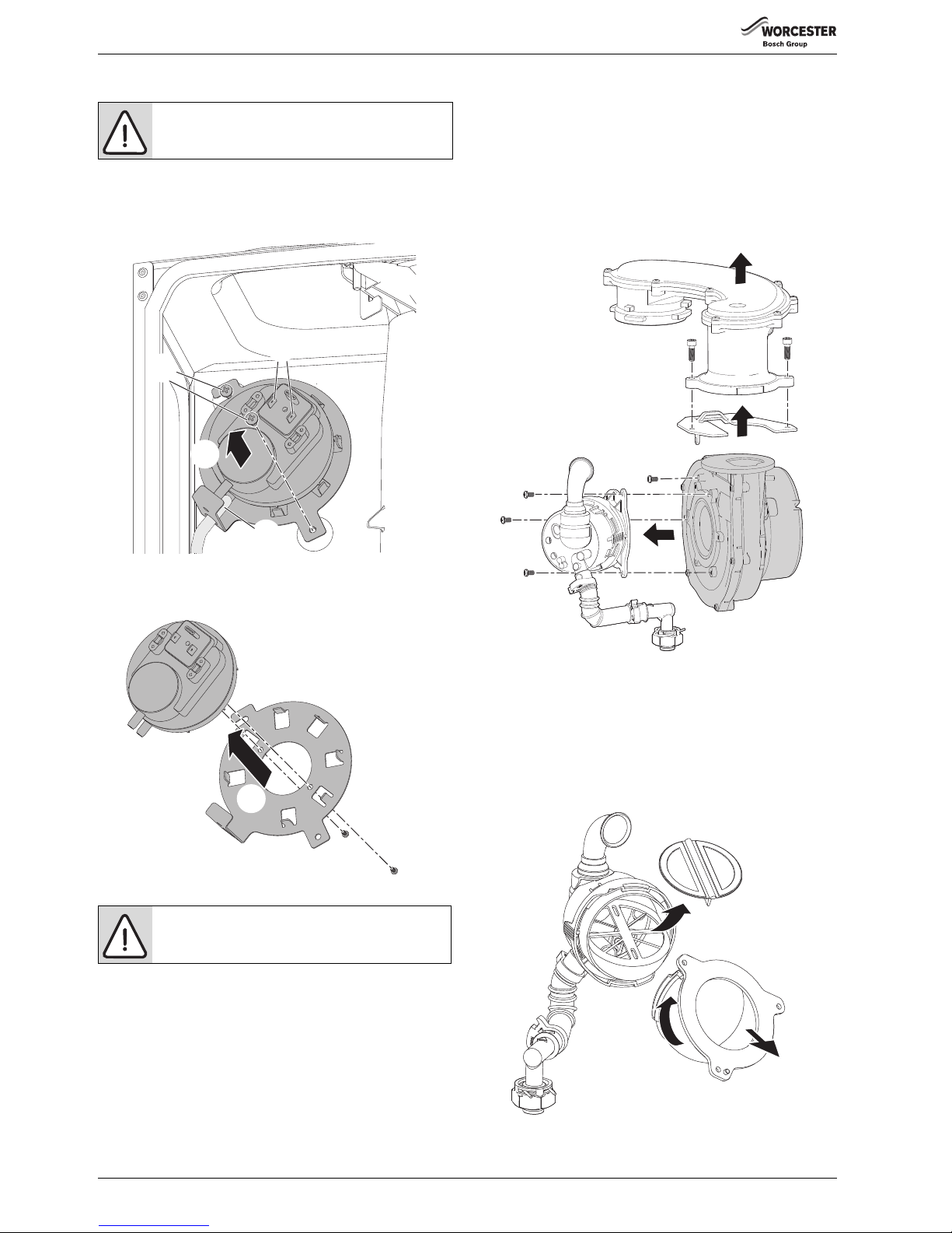
SERVICE AND SPARES
Greenstar Ri
ErP
- 6 720 813 283 (2015/07)42
7.8.8 AIR PRESSURE SWITCH
1. Remove the electrical connections.
2. Slacken the top retaining screw and remove the bottom screw.
3. Disconnect the tube.
4. Remove the Air pressure switch assembly
Fig. 76 Air pressure switch
1. Remove the two screws retaining the pressure switch to the bracket.
2. Refit the new Air pressure switch to the bracket.
Fig. 77 Air pressure switch bracket
7.8.9 FAN
▶ Remove the air/gas manifold from the boiler as described in the
previous section.
1. Remove two screws retaining the fan to the air/gas manifold.
2. Remove the air/gas manifold.
3. Remove the screw holding the retaining plate.
4. Remove the retaining plate.
5. Remove three screws and the mixing chamber.
Re-assemble with new fan ensuring seals are correctly fitted.
Fig. 78 Dismantling the air/gas manifold assembly
FLAP VALVE ASSEMBLY
1. Twist the mounting flange clockwise to release.
2. Pull mounting flange off the flap valve assembly.
3. Pull rubber flap off flap valve assembly.
▶ To replace the flap valve:
– Press the two lugs on the back of the flap into the two slots in the
flap valve assembly.
Fig. 79 Flap valve assembly
NOTICE: Pressure switch
▶ Ensure that the tube is reconnected to the pressure
switch
NOTICE: After re-assembly, check the CO/CO2 levels as
described in section 7.6 Setting the air/gas ratio.
6720644744-48.1Wo
3.
4.
1.
2.
6720644744-49.1Wo
1.
2.
4.
1.
2.
1.
3.
6.
5.
5.
5.
6720643895-81.1Wo
3.
1.
2.
6720643895-117.1Wo
Page 43
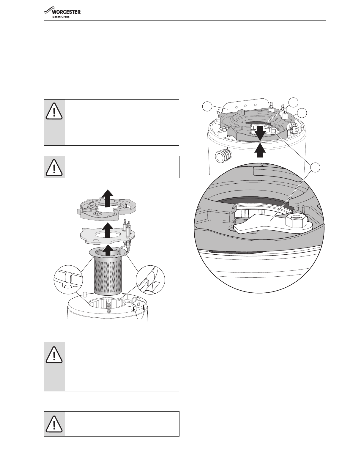
SERVICE AND SPARES
Greenstar Ri
ErP
- 6 720 813 283 (2015/07) 43
7.8.10 ELECTRODE ASSEMBLY AND BURNER
▶ Refer to figure 80 and disconnect spark electrodes and flame sensor
connection.
▶ Remove clamping plate.
1. Remove spark/flame electrode assembly from heat exchanger.
2. Remove the seal from the top of the heat exchanger.
3. Remove the burner.
▶ Replace new burner in correct position.
▶ Ensure that burner tabs, as shown in figure 80, fit correctly their
respective locations.
▶ Ensure that the seal is fitted.
▶ Replace the clamping plate.
Fig. 80 Electrode assembly and burner
7.8.11 RE-ASSEMBLY OF THE BURNER CLAMPING PLATE
▶ Ensure that the new gasket is fitted, with the electrode assembly and
gasket heat shield
▶ Locate the edge of the clamping plate [7] under the bracket [4] and
fit the retaining plate[1] hand tight
▶ Ensure that the retaining plate [1] is in the position shown in figure 81
▶ At this point the Air/Gas Manifold/Fan assembly [8] should be fitted,
engage the lugs in the slots in the clamping plate and rotate clockwise
to the stop position.
▶ Rotate the retaining plate assembly [1] in the slot on the clamping
plate [2], this will prevent the Air/Gas manifold [8] rotating back
▶ Initially there will be a gap between the clamping plate and the top of
the heat exchanger, refer to figure 81
Fig. 81 Initial location of the clamping plate
[1] Retaining plate assembly
[2] Clamping plate
[3] Gasket
[4] Bracket
[5] Underside view of the clamping plate
[6] Mating surface
[7] Location edge
[8] Air/Gas manifold assembly
▶ Tighten the nut on the retaining plate assembly [1] until the underside
face of the clamping plate mates with the top of the heat exchanger as
indicated by the two arrows in figure 83
Refer to figure 82 for detail of the clamping and mating surface [6]
▶ It is important to clamp the plate down firmly, without over tightening,
to the heat exchanger to ensure a gas tight seal
NOTICE: Heat exchanger seal
▶ If the joint between the Air/Gas manifold and heat
exchanger is disturbed sealing gasket must be
replaced.
▶ After re-assembly the combustion must be checked
using the procedure in the section 7.6 “Setting the
Air/Gas ratio”.
CAUTION: Clamping plate
▶ Ensure that the clamping plate is firmly tightened
down on top of the heat exchanger.
NOTICE: Heat exchanger seal
▶ If the joint between the Air/Gas manifold and heat
exchanger is disturbed the sealing gasket must be
replaced.
▶ After re-assembly the combustion must be checked
using the procedure in the section 7.6 “Setting the
Air/Gas ratio”.
CAUTION: Clamping plate
▶ Ensure that the clamping plate is firmly tightened
down on top of the heat exchanger.
1.
2.
3.
6720643895-61.1Wo
1
4
3
2
6720802047-03.1Wo
Page 44
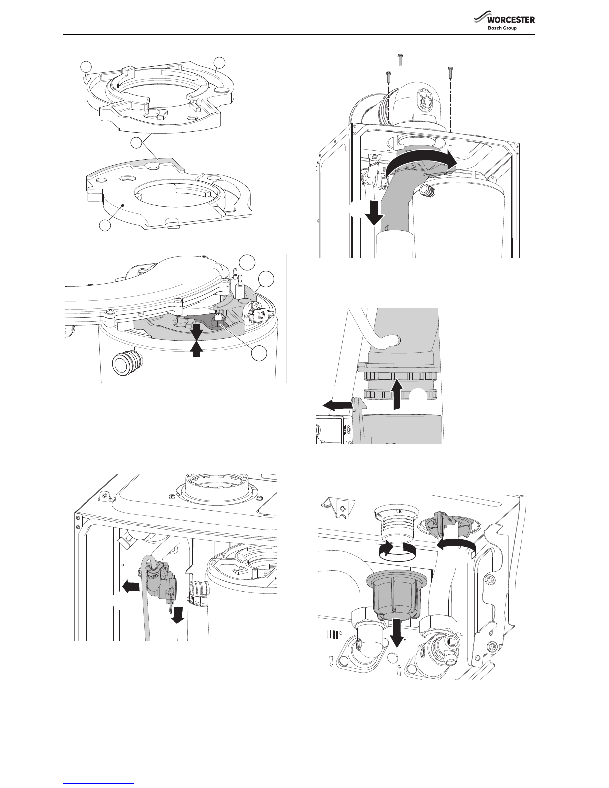
SERVICE AND SPARES
Greenstar Ri
ErP
- 6 720 813 283 (2015/07)44
Fig. 82 Clamping plate detail
Fig. 83 Clamping plate secured
7.8.12 HEAT EXCHANGER
▶ Drain the system.
▶ Remove syphon.
▶ Remove the air/gas manifold and fan.
1. Refer to figure 84, remove the clip from the elbow on the flow pipe.
2. Pull flow pipe away from heat exchanger.
Fig. 84 Flow pipe removal
1. Refer to figure 85 and re move the three screws securing the turret to
the top of the boiler.
2. Turn the upper exhaust connector anti-clockwise to release from the
hook.
3. Pull the upper exhaust connector down.
Fig. 85 Upper exhaust assembly
1. Refer to figure 86 and release the clip.
2. Move the lower exhaust connector up
▶ Remove the complete exhaust assembly.
Fig. 86 Release lower exhaust connection
1. Refer to figure 87 and unscrew the plastic nut.
2. Remove the nut from the bottom of the boiler.
3. Rotate lever to release the return pipe.
Fig. 87 Sump connections
1. Refer to figure 88 and lift the heat exchanger up to clear.
2. Pull the heat exchanger forward from the case.
5
2
7
6
6720802047-05.1Wo
6720802047-06.1Wo
8
2
1
1.
2.
6720643895-114.1Wo
1.
3.
2.
6720644744-47.1Wo
2.
1.
6720644744-52.1Wo
1.
3.
2.
Page 45
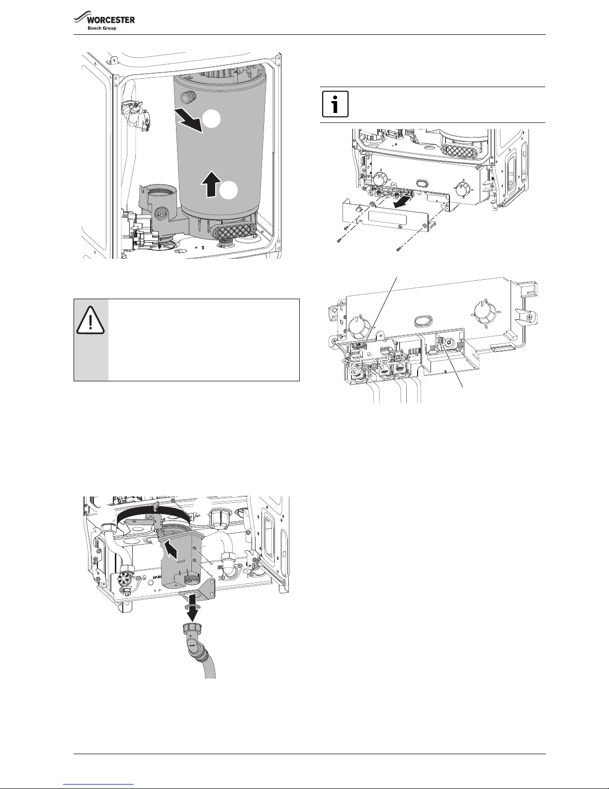
SERVICE AND SPARES
Greenstar Ri
ErP
- 6 720 813 283 (2015/07) 45
Fig. 88 Heat exchanger removal
▶ Reassemble and check combustion as stated in the air/gas ratio
section. 7.6.
7.8.13 SYPHON REMOVAL
To release the syphon from the sump:
1. Undo the plastic nut on the bottom of the syphon and move the
condensate pipe away from the syphon.
2. Remove the two screws retaining the syphon bracket.
3. Remove the bracket.
4. Remove the screw and release the syphon retaining clamp
5. Swing the clamp completely to the left away from the syphon
6. Pull the syphon towards you and remove from the sump connection.
Fig. 89 Syphon removal
7.8.14 ACCESS TO BOILER CONTROL COMPONENTS
1. Remove three screws.
2. Remove cover from control.
7.8.15 PCB FUSE
▶ Remove fuse holder with fuse F1 (1) from the control and replace with
a new fuse.
Fig. 90 Removing the connection cover
7.8.16 CODE PLUG
Refer to figure 90 for code plug replacement:
▶ Gently pull the code plug from the socket (2).
▶ The code plug should be left attached to the frame of the boiler by its
plastic safety thread.
7.8.17 TRANSFORMER/PCB
To change either the PCB, F2 fuse or transformer:
▶ Remove two screws securing the control.
▶ Pull the control forward.
▶ Lower the control to align the slots at the top of the control with the
lugs on the boiler framework.
▶ Hang control on two lugs on boiler framework.
1. Unscrew the three screws in the control panel.
2. Remove the connections cover and disconnect all electrical
connections from the control.
3. Remove the control from the boiler.
4. Remove the four screws retaining the rear panel of the control.
5. Remove the rear panel.
6. Remove the transformer cover.
7. Remove the printed circuit board.
NOTICE: CO/CO2 CHECKS
▶ If the joint between the Air/Gas manifold and heat
exchanger is disturbed sealing gasket must be
replaced.
▶ After completing the service of the appliance, the CO/
CO
2
must be checked and set to the limits shown in
“Setting the air/gas ratio” in section 7.6.
6720643895-115.1Wo
1.
2.
6720644744-42.1Wo
1.
2.
3.
4.
5.
6.
A spare 2A fuse for F1 clipped onto the inside of the
cover.
6720644744-53.1Wo
1
2.
1.
2
Page 46
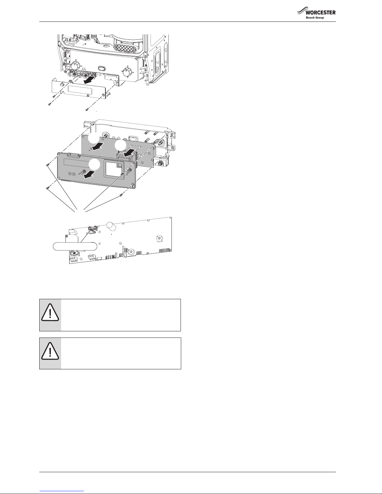
SERVICE AND SPARES
Greenstar Ri
ErP
- 6 720 813 283 (2015/07)46
Fig. 91 Transformer/PCB/Fuse access
▶ Remove the code plug from the old control board.
▶ Fit the code plug into the new control board.
▶ Re-assemble in reverse order.
NOTICE: CODE PLUG
▶ Ensure that the code plug is fitted to the new control.
▶ The appliance will indicate an error and will not
function correctly.
NOTICE: CO/CO
2
▶ After completing the service of the control, the CO/
CO2 must be checked and set to the limits shown in
“Setting the air/gas ratio” in section 7.6.
3.
4.
6720813283-04.1Wo
2.
1.
F2, 1.25A fuse
5.
6.
7.
4.
Page 47
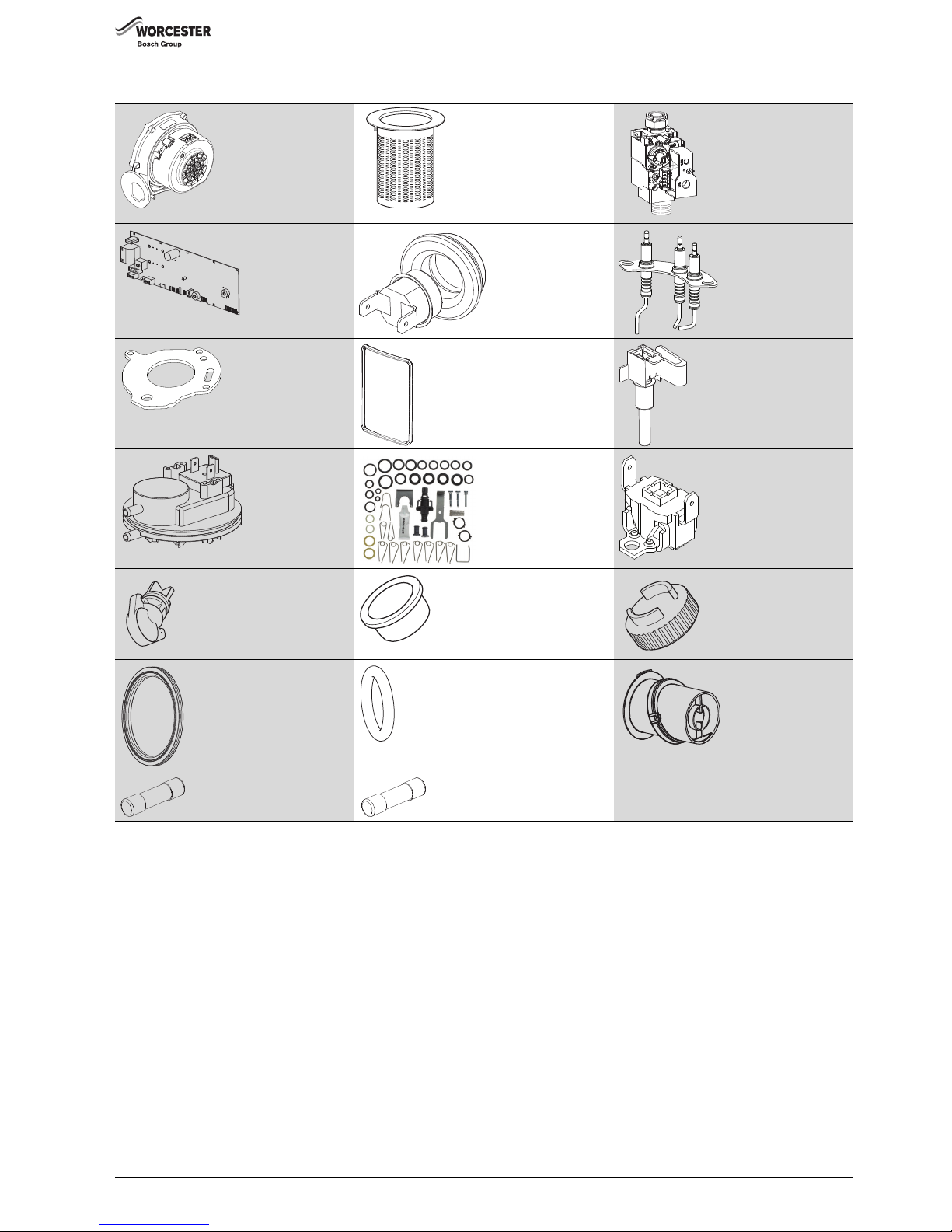
SERVICE AND SPARES
Greenstar Ri
ErP
- 6 720 813 283 (2015/07) 47
7.9 SHORT PARTS LIST
Fan
8 716 116 067 0
GC No. H26 536
Burner 12 & 15Ri:
8 716 116 379 0
GC No. H26 537
18 & 24Ri:
8 716 120 619 0
GC No. H26-538
Gas Valve
12/15/18 & 24Ri
8 716 111 325 0
GC No. H26 540
Control board
8 718 687 164 0
H26-541
Flue overheat
thermostat (grommet
type)
8 710 506 267 0
Electrodes (including
gasket)
8 718 107 087 0
Gasket - burner WB6
8 716 110 534 0
Seal - Inner case/mantel
8 716 106 635 0
H26-545
Flow temperature sensor (NTC)
8 716 106 688 0
GC No. H26 542
Air pressure switch
8 716 106 633 0
G.C. No. H26 543
Seals kit
8 716 107 224 0
GC No. H10 876
High limit stat
8 707 206 196 0
GC No. H26 584
Flue sample plug
- vertical adapter
8 710 506 199 0
Flue sample plug
- air intake
8 716 111 253 0
Flue sample plug
- gas outlet
8 716 111 252 0
Sump gasket
8 716 113 829 0
O ring - Syphon
8 716 113 851 0
Terminal end
8 716 111 209 0
Fuse F1
8 716 156 000 0
GC No. E27-716
Fuse F2
8 716 156 001 0
Wall mounting template:- 8 718 689 070 0
Page 48
FAULT FINDING AND DIAGNOSIS
Greenstar Ri
ErP
- 6 720 813 283 (2015/07)48
8 FAULT FINDING AND DIAGNOSIS
8.1 FAULT FINDING
The electronic control system for this boiler incorporates a blue central indicator. This normally confirms the permanent mains supply but, by flashing
at different rates during a fault, provides a guide to the cause as listed.This fault finding system assumes that the appliance has been operating normally
until the time of failure (i.e. not a first installation error).PRELIMINARY CHECKS: Preliminary electrical system checks are the first electrical checks to
be carried out during a fault-finding procedure. On completion of the Service/Fault-Finding task which has required the breaking and remaking of
electrical connections, check:
(a) EARTH CONTINUITY, (b) SHORT CIRCUIT CHECK, (c) POLARITY and (d) RESISTANCE TO EARTH.
This fault finding information is for guidance only. Worcester cannot be held responsible for costs incurred by persons not deemed to
be competent.
Blue light
indication Fault Possible solution/check
No light No power at control
board
Permanent mains supply to boiler.
Boiler mains switch ON.
Fuse F1 - 2A Slow blow.
Fuse F2 - 1.25A Anti-surge.
Transformer (both coils below 100 .
Otherwise replace control board.
Light ON Boiler ON but not
operating during
demand
Live demand at ST2 terminal LR - is there a demand?
Manual bypass is open.
If CH is working check HW controls
If HW is working check CH controls (i.e. external diverter valve, frost stat, room stat/programmer.
Otherwise replace board.
Slow flash
(mostly off,
flashes on)
Ignition lockout ▶ Gas present and at correct pressure?
▶ Gas valve
– Check that there is 35V d.c. to each solenoid
– Check the resistance of each solenoid:
Top solenoid = 380 10% (342 - 418 )
Bottom solenoid = 190 10% (171 - 209 )
▶ Combustion CO
2
level.
▶ Flue condition.
–Blocked flue?
▶ Blocked condensate pipe or frozen condensate.
▶ Gas valve adjustment.
▶ Ignition electrodes/harness/connections.
– Check for condition and resistance of leads
(approximately 2100 )
▶ Otherwise replace control board
Slow flash
(mostly on,
flashes off)
Flue overheat Flue temperature too high.
▶ Heat exchanger baffles removed and not refitted.
Heat exchanger overheat ▶ Heat exchanger blocked
▶ Water pressure
▶ All air vented
▶ Pump/harness/connections.
▶ Water leaks/blockage
▶ Safety thermostats/low voltage wiring harness/connections
▶ Otherwise replace control board
Flue pressure switch
Blockage in the flue system.
Fast flash Volatile lockout (sensor,
fan or code plug)
▶ Temperature sensors
– Check condition and continuity of leads
– Check resistance of sensor (8k - 20k )
▶Fan
– 230V A.C. across the live (purple) and neutral (brown)
▶ Fan lead
– Check continuity
▶Code plug
– Is code plug missing or not inserted properly.
2 pulses Service mode switch in min. position
5 pulses Service mode switch in max. position
Table 31 Fault finding
Page 49
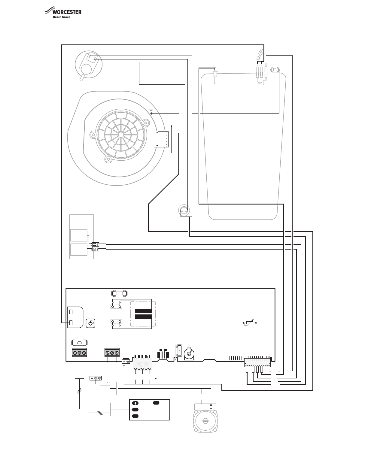
FAULT FINDING AND DIAGNOSIS
Greenstar Ri
ErP
- 6 720 813 283 (2015/07) 49
8.1.1 INTERNAL WIRING DIAGRAM
EXTERNAL
PUMP
FLUE
OVERH EAT
STAT
L
N
LP NP LR
Earth
MAINS
SUPPLY
SPARK
TRANSFORM ER
ST9
ST6
ST5
ST2
ST1
DIAGNOSTIC
INTERFACE
CODE
PLUG
MODE
SWITCH
Slow 2 A fuse ,
AC 230 V
Slow T1.25 A fuse
CH TEMPER ATURE
CONTROL
PRESSURE
SWITCH
230V WIRING CENTER/
JUNCTION BOX
FAN
Colour sequence †
SL
L
N
Min
Max
Norm
ON/OFF
SWITCH
230V/AC
25V
Red
Blue
Violet
Orange
Live
Neutral
Colour sequence †
FLAME SE NSE
ELECTRODE
SPARK
ELECTRODES
OVERH EAT
STAT
Green
GAS
VALV E
SAFETY
SOLENOID
SAFETY
SOLENOID
6720644744-27.2Wo
† Fan wiring:
Live = purple
Neutral = brown
F1
F2
FLOW TEMP.
SENSOR (NTC)
Pump Neutral
Pump Live
Switched Live
LP NP LR
L
N
Page 50
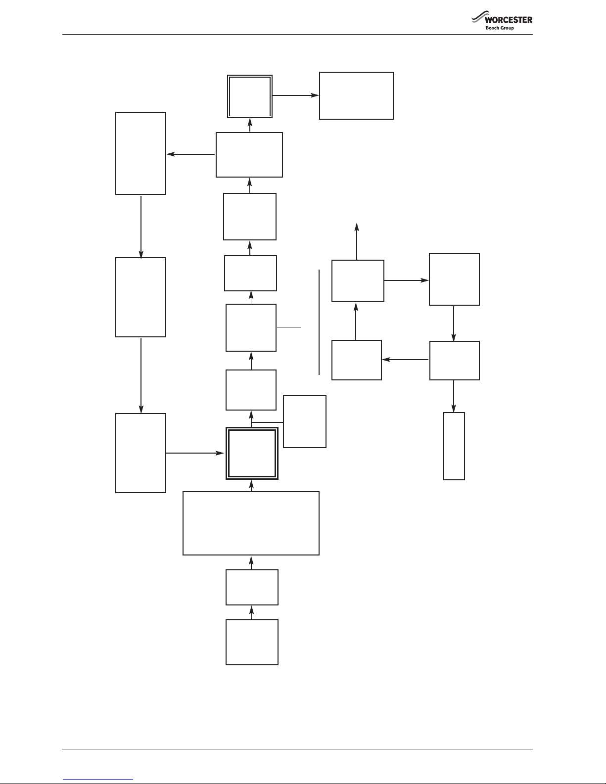
FAULT FINDING AND DIAGNOSIS
Greenstar Ri
ErP
- 6 720 813 283 (2015/07)50
8.2 BOILER FUNCTION
Fig. 92 Boiler function
NO
YES
MAINS
POWER
SUPPLY
ON
BOILER
DEMAND
Fan to
start
speed.
Pump ON.
IGNITION
SEQUENCE
(see detail)
BLUE
LIGHT
ON
BURNER
LIT?
GREEN
FLAME
LIGHT
ON
Stop spark
and gas.
Wait
10 seconds
5th
attempt?
LOCKOUT
45 second
stabilisation
period.
Fan
modulation
to achieve
set
temperature
(40-82°C)
END OF
BOILER
DEMAND
Gas valve
OFF
Pump run 3
minutes
Fan run 30
seconds
Over temperature shut-
down if water tempera-
ture is 5°C above set
value.
Gas valve OFF.
Fan overrun
30 seconds
3 minute pump
over run
Spark
ignition
and gas
4 seconds
NO
YES
Room
thermostat and/or
mains
programmer ON
(or link fitted at
ST10)
AND
Facia mounted
programmer (if
fitted) ON
AND
Temperature
control knob
ON
IGNITION SEQUENCE
6720644744-60.1Wo
Page 51
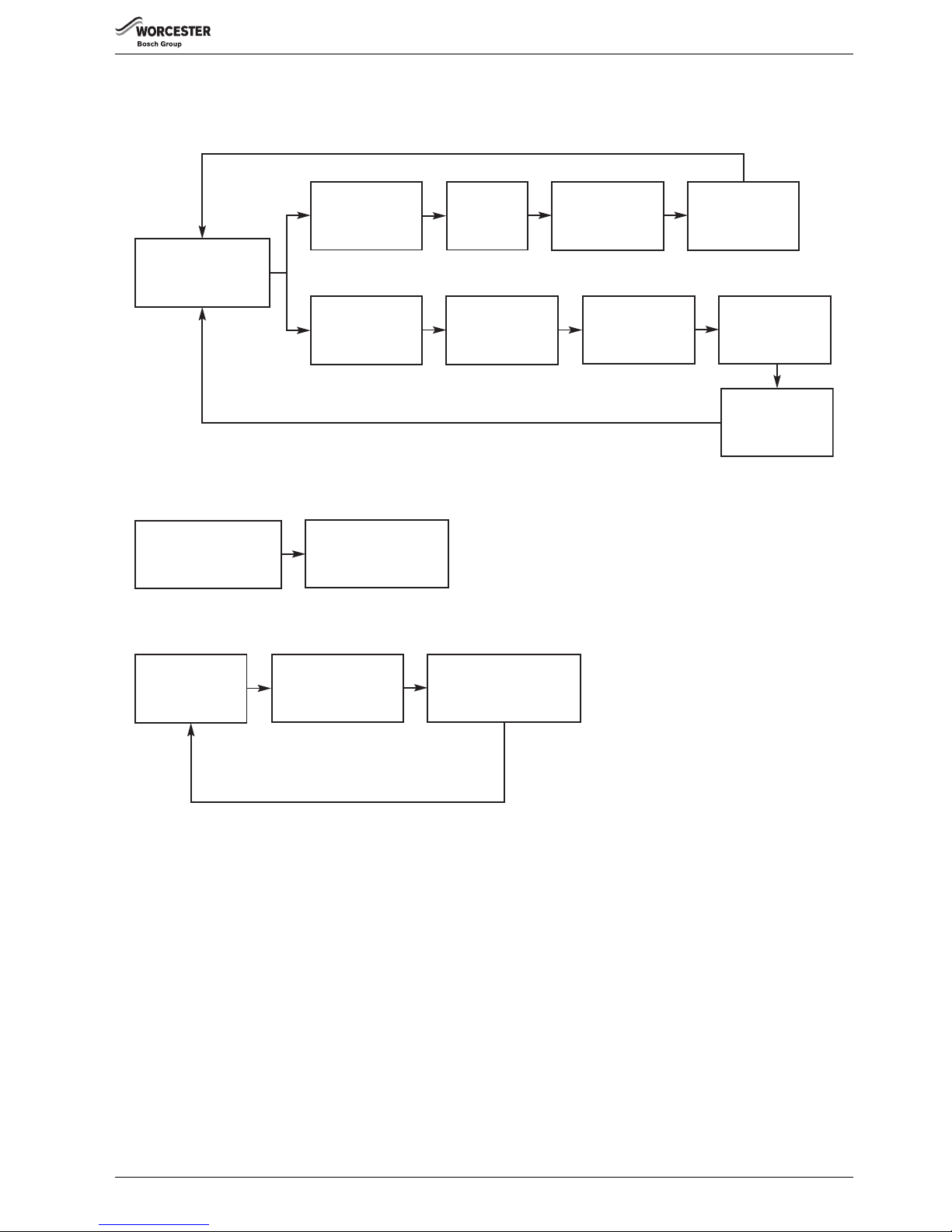
FAULT FINDING AND DIAGNOSIS
Greenstar Ri
ErP
- 6 720 813 283 (2015/07) 51
8.3 PROTECTION FUNCTION
Fig. 93 Protection function
Internal boiler
temperature
between
8°C & 5°C
Boiler automatic
frost function
(monitors internal boiler
primary temperature)
Internal boiler
temperature
below 5°C
Internal boiler
temperature
rises above 9°C
Pump runs
Pump switches off
after a 3 minute
overrun period
Internal boiler
temperature
rises above 12°C
Central heating
demand switches
off
Pump switches off
after a 3 minute
overrun period
Central heating
demand is activated
Pump runs for 3 minutes
to dissipate heat from
the boiler into the system
End of boiler demand
(central heating or
domestic hot water)
AUTOMATIC INTERNAL FROST FUNCTION
PUMP OVERRUN FUNCTION
A central heating demand
activated, pump runs
normally
Pump runs 5 seconds
every 24hrs from
last time pump ran
No central heating
demand after
a 24hr period
PUMP ANTISEIZE FUNCTION
6720643895-111.1Wo
Page 52

Greenstar Ri
ErP
- 6 720 813 283 (2015/07)52
NOTES
Page 53

Greenstar Ri
ErP
- 6 720 813 283 (2015/07) 53
NOTES
Page 54
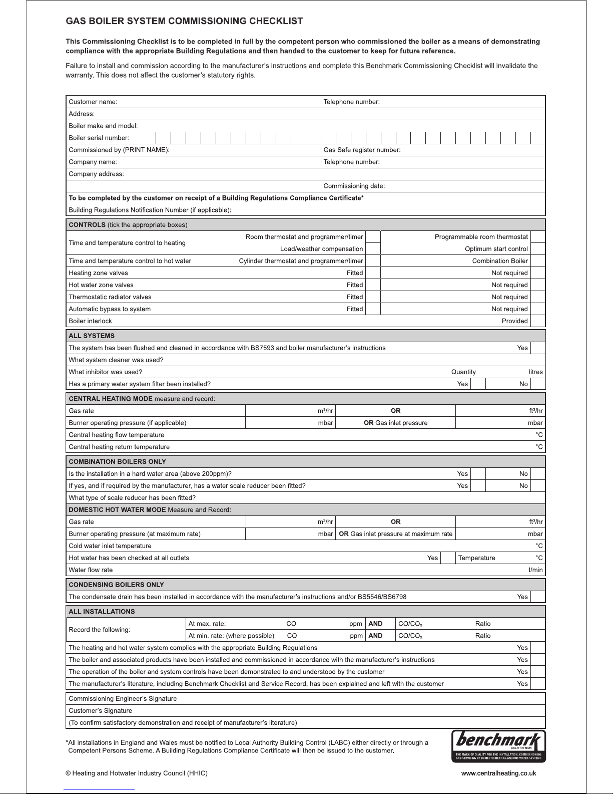
Page 55
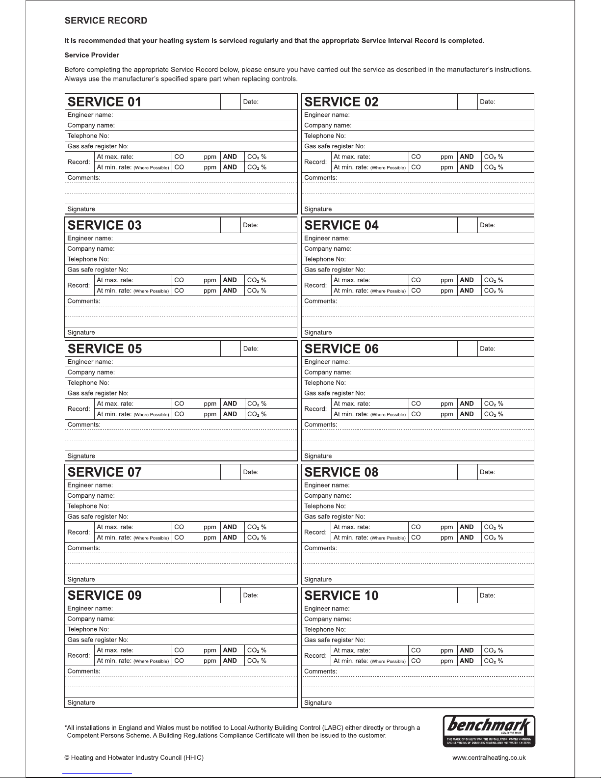
Page 56

Worcester, Bosch Group
Cotswold Way, Warndon, Worcester WR4 9SW.
Tel. 0330 123 9559
Worcester, Bosch Group is a brand name of Bosch Thermotechnology Ltd.
worcester-bosch.co.uk
6 720 813 283 (2015/07)
WORCESTER, BOSCH GROUP:
TECHNICAL SUPPORT: 0330 123 3366
APPOINTMENTS: 0330 123 9339
SPARES: 0330 123 9779
LITERATURE: 0330 123 9119
TRAINING: 0330 123 0166
SALES: 0330 123 9669
 Loading...