

Green Speed GT Series Manual

folding trike owner manual
ride me
fold me
5/31 Rushdale Street, Knoxfield, VIC, Australia, 3180.
+61 3 9753 3644 +61 3 9753 2027
www.greenspeed.com.au info@greenspeed.com.au
Congratulations on your purchase of a Greenspeed folding trike.
We believe that you have purchased the finest recumbent tricycle
available in the world today. It is also our belief that the present
level of motorised transport on this small planet is not sustainable,
in environmental and social terms. Thus your Greenspeed has
been designed for everyday use, whether it be shopping,
commuting, touring the world, or just exercising and having fun!
With care, it should last a lifetime.
Included in this manual are instructions on how to assemble,
maintain and get the most from your Greenspeed.
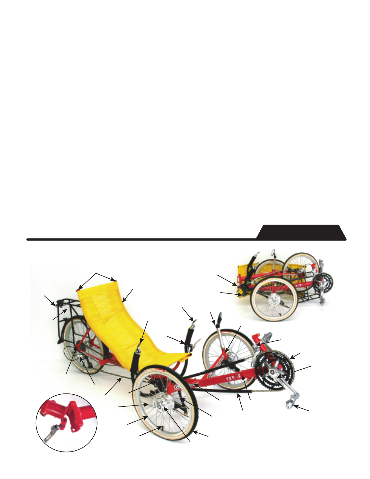
Pedal
(optional
cleated)
Cranks
Kingpin
Steering Rods
Boom
Cross Member
Spokes
Rim
Tube Valve
Tyre
Chain
Rear Derailluer
Front Derailleur
Front Hub
Rack
(optional
extra)
Bar End Shifter
Front Derailleur
Bar End Shifter
Rear Derailleur
Brake Lever
Seat
Tail Light and Flag Mounts
Folded Trike
Hinge Mechanism
Handle bar
bosses
Mirror Mount
& Mirror
Chainrings
Tricycle Anatomy
Chain Guide Tube
Quick Release
Skewer
Pulley
Hinge
Tail Light Mount
9
9
9
9
9
10
10
10
10
10
11
11
12
12
12
12
13
13
13
13
14
14
14
3
3
3
4
4
5
6
6
6
7
7
8
8
Resources
Rack
Trailers
Grab Handles
Hydration
Headrests
Front Fenders
Pannier Bags
Lighting Sets
Speedos
Fairings
Rack
Trailers
Grab Handles
Hydration
Headrests
Front Fenders
Pannier Bags
Lighting Sets
Speedos
Fairings
Accessories
Pedals
1st Ride
Doorways
Stamina
Gears
Stability
Tyre Repair
Pedals
1st Ride
Doorways
Stamina
Gears
Stability
Tyre Repair
Riding Tips
Chain
Steering
Tyre Pressure
What Tools
should I take?
Trouble shooting
Chain
Steering
Tyre Pressure
What Tools
should I take?
Trouble shooting
Maintainence
Tools Required
Frame Assembly
Wheels
Seat
Crank Extension
Fitting the Chain
Chain Length
Folding Handlebars
Cables - Deraileurs
Cables - Brakes
Gear Cable Adjustment
Steering Alignment
Regular Folding
Tools Required
Frame Assembly
Wheels
Seat
Crank Extension
Fitting the Chain
Chain Length
Folding Handlebars
Cables - Deraileurs
Cables - Brakes
Gear Cable Adjustment
Steering Alignment
Regular Folding
Assembly
Anatomy 2
Contents
Anatomy
Assembly
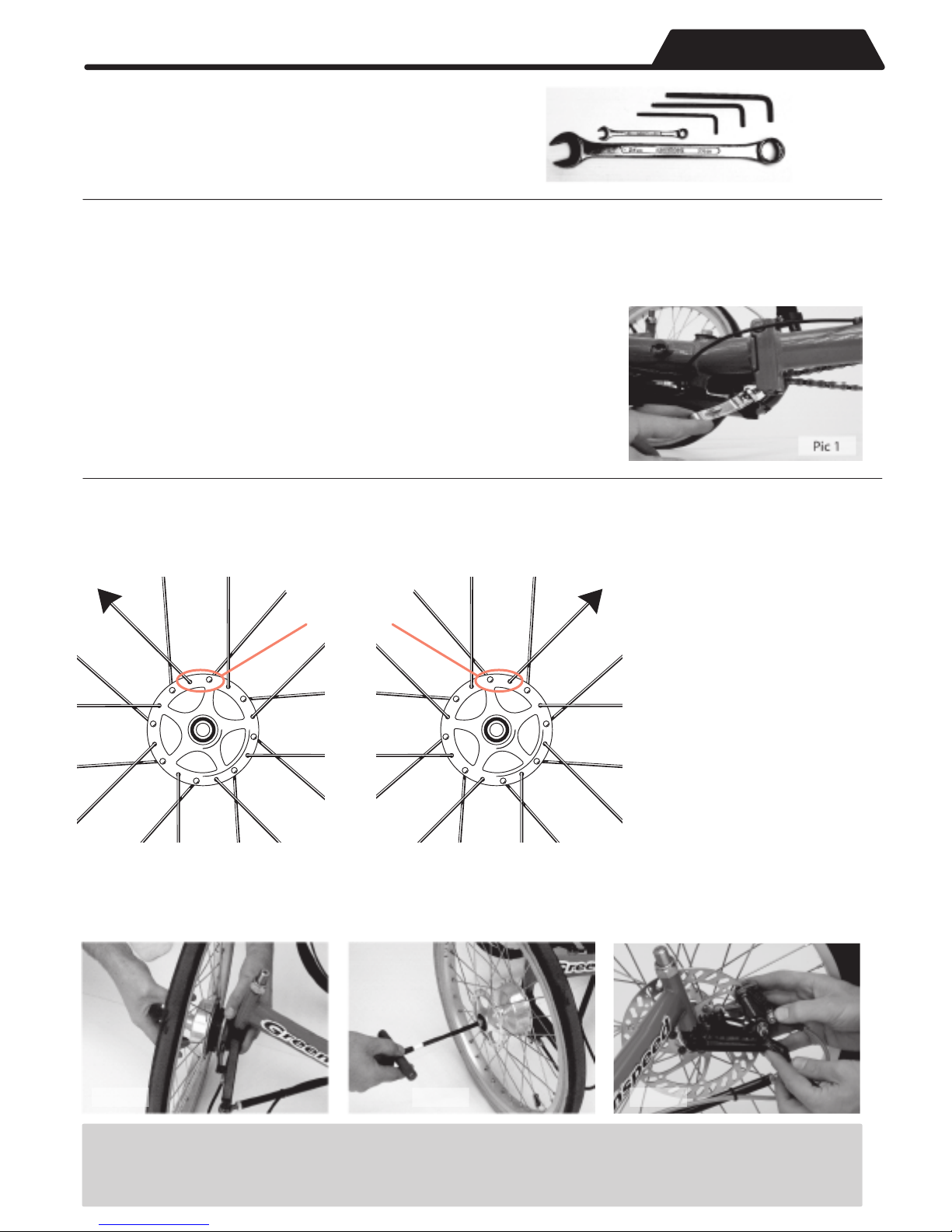
Tools Required for Assembly
The trike's main feature is its ability to be folded
/ assembled with the minimum of tools / effort.
6,5 and 4mm
Allen keys
2x 9 and a 24mm wrench
Frame Assembly
Assembly of the folding trike is as follows. If you are assembling from a boxed state, you start by
unpacking it all carefully. Once all the packaging has been removed, the fun bit begins.
The frame is now ready to unfold. Start by holding the back section
and lifting it away from the frame and straightening the frame out.
Note the quick release needs to be rotated all the way forward (pic
1) for the safety pin to be released to allow the frame to unfold all
the way. Once it has been unfolded all the way, you rotate the
Quick Release rearward and tighten it up.
Wheels
Outside spoke
pointing left
Left Side Wheel
Fig. 2.1
Outside spoke
Look at
pointing right
the top
of the hub
Right Side Wheel
Next you install the
wheels. Put the rear
wheel in first and tighten
up the quick release. Now
install the front wheels.
Fig 2.1 shows that there
are left and right wheels.
The right hand wheel has
been tagged for your
reference. Be sure to try
and install them this
way in the future to
increase spoke life. The
front hubs shown are
drum brakes, and it is the
same priniple when
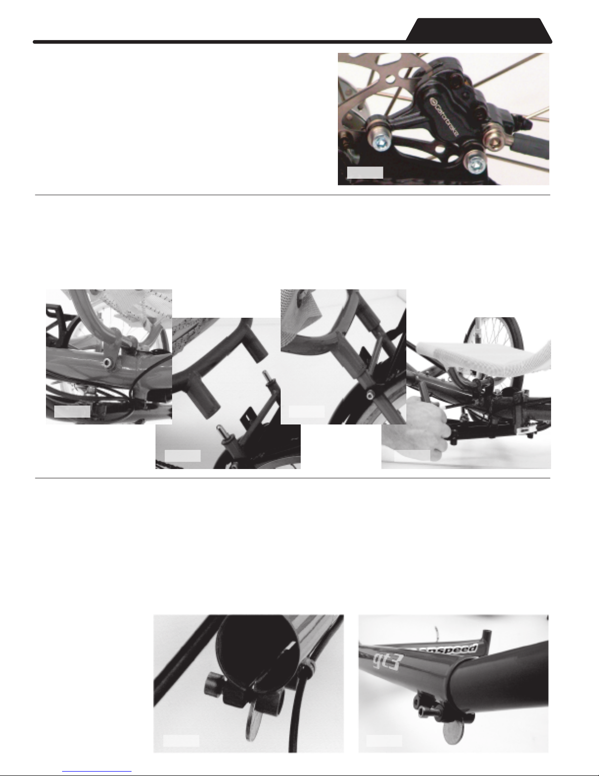
brake hub. The brake assembly (Pic. 2.2) may need some re-centring for the wheel to slide all the
way on. Use the provided short cap screw (Pic. 2.3) to hold the wheel on. Do the same on the other
side. Disc wheels will then need the calipers installed. Start with the forward most screw and
Pic. 2.2 Pic. 2.3
Important. If you are unfamiliar with a quick release mechanism, PLEASE get a Greenspeed Dealer or local
bike shop/friend show you the finer points of safe use. The quick release on the frame is slightly different to
a wheel quick release in that it requires a 10mm wrench to add tightness to it should the adjustment loosen
of with time/wear. Please keep it tight enough that you can release/tighten with moderate hand effort.
Pic. 2.4
Pic. 3.1
Pic. 2.5
Pic. 3.3
Pic. 3.2 Pic. 3.4
Pic. 4.1 Pic. 4.2
taking care to not
damage the
protective sleave
inside the end of
the frame. Hint
starting it off with
a slight angle can
help so as not to
catch the edge of
the sleeve (Pic. 4.2)
Now the seat is installed, you can install the crank extension. This will require some fiddly work, but
you shouldn't have to remove it again unless you need to pack it 'really' small. Firstly loosen the
screws on the underside of the boom with a 6mm Allen key and completely remove the front screw
and thread it in from the other direction. Place a coin in the slot (Pic. 4.1) and tighten the screw so
that the slot starts to open (approx two complete turns). Note don't place the coin too far in or it will
stop the crank extension from going in, AND careful to not over tighten, as this may make it harder to
fit the extension and possibly damage the frame. Next step is to insert the extension into the boom
Crank Extension
The seat can now be fitted. Start by inserting the long cap screw through the seat tag and frame (Pic.
3.1) and doing the cap screw up finger tight. The seat can now be pushed onto the seat pins (Pic. 3.2).
You should just need to apply pressure to the top of the seat by pushing down until it stops (Pic. 3.3).
Now tighten the cap screw with a 6mm Allen key (Pic. 3.4).
Seat
fit the washers either side of the caliper mount (Pic. 2.4).
Leave this screw loose so it is easier to put the second
screw in with its washers either side of the caliper
mount. Tighten up both of the bolts. Your pads are self
adjusting, so should center themselves either side of the
disc after use. However, if when you put the caliper on,
you can see that the slot for the pads is obviously out of
alignment you may need to change spacers. Please see
your dealer about having the new ones fitted.
Assembly
Assembly
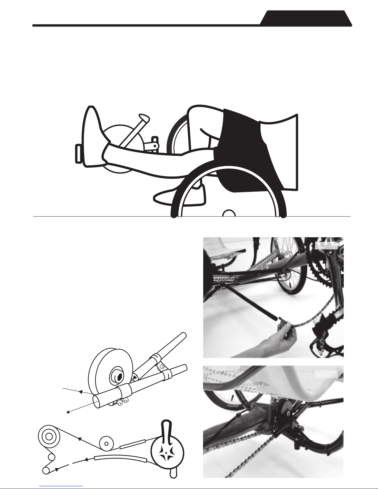
Remove the coin and refit the screw in its correct position and pinch up one of the screws. Lightly
grease the pedal threads and fit the pedals. Hint left and right pedals have different threads, the
right one tightens clockwise, the left one counterclockwise. Tighten the pedals. Sit on the seat and
place your heels on the pedals and adjust the extension so that your leg is straight when in the
outstretched position (Fig. 4.3). To align the extension, sight along the top of the bottom bracket
to the front of the seat cover and rotate the extension until they line up. Tighten screws when
happy. Note you may find small adjustments can make a big difference, so play around with this
setting before you do a long ride.
Fig. 4.3
Fitting the Chain
Fit the chain next following the diagrams shown
below. Start by feeding the chain through the
front derailleur cage, down the chain tube, under
the pulley, over the sprockets and down through
the rear derailleur (Fig. 5.1). Put the rest through
the lower tube (Pic. 5.2). Note make sure the chain
is not twisted inside the tubes. You are now ready
to join the chain. Check the Chain Adjustment
section on page 5 to make sure the chain is the
right length. Note if this is not correct, damage
may occur to your rear derailleur.
Fig. 5.1
to rear
sprockets
(cluster)
Pic. 5.2
Pic. 5.3
to rear
derailleur
join
chain fitting
chain line
 Loading...