

Page 1

CONTENT
INTRODUCTION ..................................................................................................................................1
SAFETY RULES ....................................................................................................................................2
COMPONENT IDENTIFICATION.....................................................................................................4
POWER PANEL LIST ..........................................................................................................................6
MAIN TECHNICAL SPECIFICATION AND DATA TABLE 1 ......................................................9
MAIN TECHNICAL SPECIFICATION AND DATA TABLE 2 ....................................................10
RUNNING CONDITION .................................................................................................................... 11
E
NVIRONMENT REQUIREMENT ............................................................................................................11
G
AS REQUIREMENT............................................................................................................................. 11
OPERATION........................................................................................................................................ 12
P
RE-START PREPARATION....................................................................................................................12
Generator Location........................................................................................................................ 12
Remove tightening brackets ...........................................................................................................12
Install the Support Leg (only for CC1500~CC5000 frame type generator sets)............................12
Add Engine Oil...............................................................................................................................13
Connect Generator to Gas Supply Source .....................................................................................13
Connect the Storage Battery ..........................................................................................................13
Grounding ......................................................................................................................................14
S
TARTING THE ENGINE ........................................................................................................................15
C
ONNECTING ELECTRICAL LOADS ......................................................................................................16
STOPPING THE ENGINE ........................................................................................................................16
P
OWER MANAGEMENT........................................................................................................................ 16
W
AT TA G E REFERENCE CHART............................................................................................................. 17
MAINTENANCE .................................................................................................................................18
E
NGINE MAINTENANCE....................................................................................................................... 19
Engine Oil ......................................................................................................................................19
Spark Plug...................................................................................................................................... 19
Air Filter ........................................................................................................................................20
Air-fuel Mixer.................................................................................................................................20
Cleaning.........................................................................................................................................20
G
ENERATOR MAINTENANCE ...............................................................................................................21
M
AINTENANCE SCHEDULE ..................................................................................................................21
COMMON BREAKDOWNS AND TROUBLESHOOTING ........................................................... 22
STORAGE ............................................................................................................................................23
E
NGINE STORAGE................................................................................................................................23
G
ENERATOR STORAGE ........................................................................................................................ 23
TRANSPORTATION ..........................................................................................................................23
ACCESSORY ....................................................................................................................................... 24
H
OW TO INSTALL FOUR-WHEEL GENERATOR SET .................................................................................24
H
OW TO INSTALL TWO-WHEEL (CC3000/4000/5000) GENERATOR SET ................................................25
HOW TO INSTALL TWO-WHEEL (CC1500/2000) GENERATOR SET.........................................................26
H
OW TO OPERATE DUAL FUEL (NG/LPG) GENERATOR SET ..................................................................27
GENERATOR CIRCUIT DIAGRAM ............................................................................................... 28
Page 2
Introduction
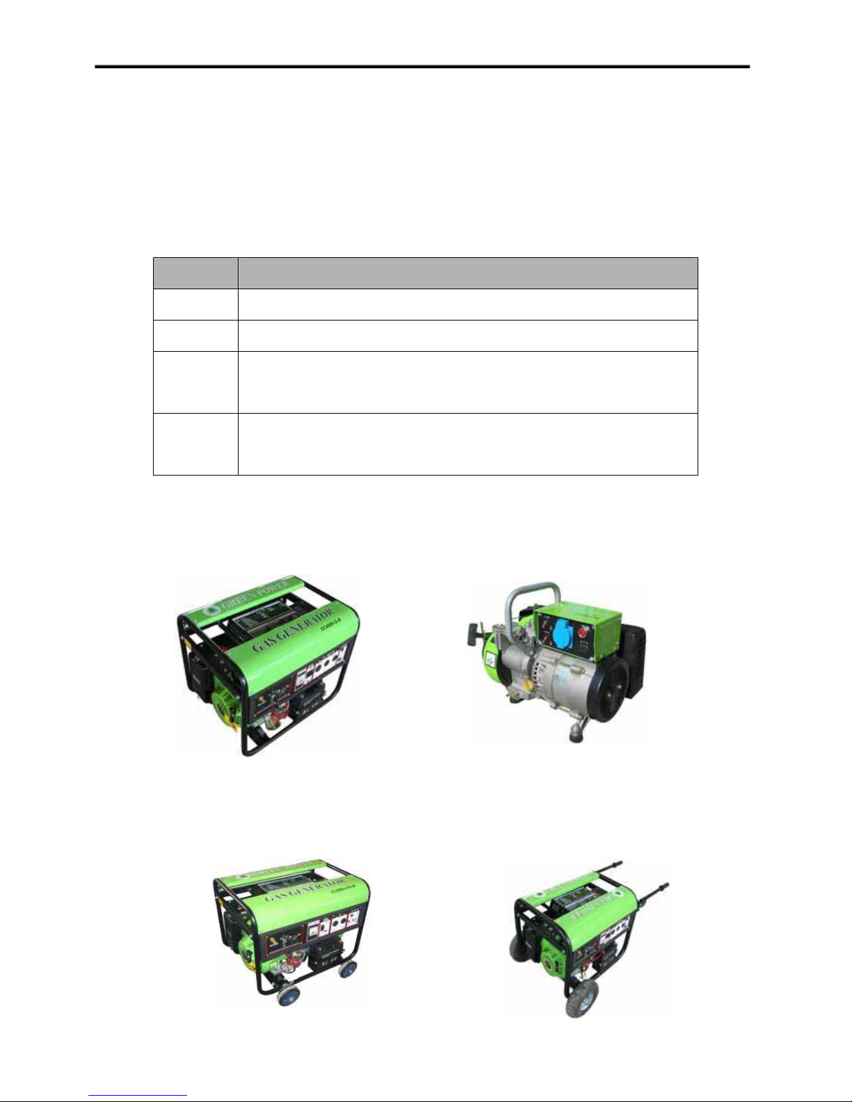
“GREEN POWER” series gas powered generator set, they are mainly divided into frame
type, four-wheel type, handcart type and portable type on structure; and LPG type, NG
type, MG type and dual-fuel (LPG/NG) type on fuel.
Meaning of product model
For example: CC2000-LPG-B
ITEM MEANING
CC Corporation code, Shanghai “Chenchang” Power Technology Co., Ltd.
2000 product power code, maximum output power 2000 W.
LPG Fuel abbreviation. LPG: liquefied petroleum gas; NG: nature gas; MG:
methane gas; G: multi-fuel, LPG/NG, LPG/MG, NG/MG.
B
generator set frame code. B: frame type; X: portable type; L: four-wheel
type; T: handcart type.
Main types as follows:
Frame type
Four-wheel type
Portable type
Handcart type
1
Page 3

Safety Rules
ˈ
WARNING
Please read and understand this manual thoroughly before operating your generator.
Failure to follow instructions could result in serious injury or death.
WARNING
Exhaust gas contains poisonous carbon monoxide, which is harmful to the health. Never
use the generator set at the confined places or poor ventilated locations. If it’s necessary
to run the generator set, be sure to provide the adequate ventilation.
DANGER
Generator produces powerful voltage.
DO NOT touch bare wires or receptacles. DO NOT use electrical cords that are worn,
damaged or frayed. DO NOT operate generator in wet weather. DO NOT allow children or
unqualified persons to operate or service the generator. DO NOT use a ground fault circuit
interrupter (GFCI) in damp areas and areas containing conductive material such as metal
decking. Use approved transfer equipment to isolate generator from your electric utility
and notify your utility company before connecting your generator to your power system.
WARNING
Sparks can result in fire or electrical shock.
When servicing the generator:
Disconnect the spark plug wire and place it where it cannot contact the plug. DO NOT
check for spark with the plug removed. Use only approved spark plug testers.
WARNING
Running engines produce heat. Severe burns can occur on contact. Combustible
material can catch fire on contact.
DO NOT touch hot surfaces. Avoid contact hot exhaust gas. Never touching the
equipment until it’s cool. Maintain at least three feet of clearance on all sides to ensure
adequate cooling. Maintain at least five feet of clearance from combustible materials.
DANGER
Propane (LPG) and nature gas (NG) is highly flammable and explosive. Fire or
explosion can cause severe burns or death if the gas is ignited.
Before starting the generator
damage or leaks, attach only approved tanks that have been properly filled by an
approved station, do not light or smoke cigarettes, replace the hose at the first sign of a
leak or if age-cracking becomes apparent.
When starting the generator do not attempt to start a damaged generator, make certain
that the LPG tank, air filter, spark plug, fuel lines and exhaust system are properly in place,
make certain that the generator resting firmly on level ground.
inspect your LPG tank and NG pipeline and valve for
2
Page 4

When operating the generator do not move or tip the generator during operation, do not
tip the generator or allow oil to spill.
When transporting or servicing the generator make certain that the generator is
disconnected and properly shut off, disconnect the spark plug wire.
When storing the generator store away from sparks, open flames, pilot lights, heat and
other sources of ignition.
WARNING
Rapid retraction of the starter cord will pull hand and arm towards the engine faster
than you can let go. Unintentional startup can result in entanglement, traumatic
amputation or laceration. Broken bones, fractures, bruises or sprains could result
in.
When starting engine, pull the starter cord slowly until resistance is felt and then pull
rapidly to avoid kickback. DO NOT start or stop the engine with electrical devices plugged
in.
WARNING
The battery contains acid. Acid is strongly corrosive.
DO NOT use, store or expose the battery in high temperature situations, as in the direct
sunlight, inside automobiles during hot weather, directly in front of a heater, etc. Be sure to
turn off the equipment and remove the battery after use.
CAUTION
Exceeding the generator’s running capacity can damage the generator and/or electrical
devices connected to it. DO NOT overload the generator. Start the generator and allow
the engine to stabilize before connecting electrical loads. Connect electrical equipment in
the off position, and then turn them on for operation. Turn electrical equipment off and
disconnect before stopping the generator. DO NOT tamper with the speed governor. DO
NOT modify the generator in any way.
CAUTION
Improper treatment or use of the generator can damage it, shorten its life and void your
warranty. Use the generator only for intended use. Operate only on level surfaces. DO
NOT expose generator to excessive moisture, dust, or dirt. DO NOT allow any material to
block the cooling slots. If connected devices overheat, turn them off and disconnect them
from the generator. DO NOT use the generator if electrical output is lost, equipment
sparks, smokes or emits flames and equipment vibrates excessively.
3
Page 5
Component Identification
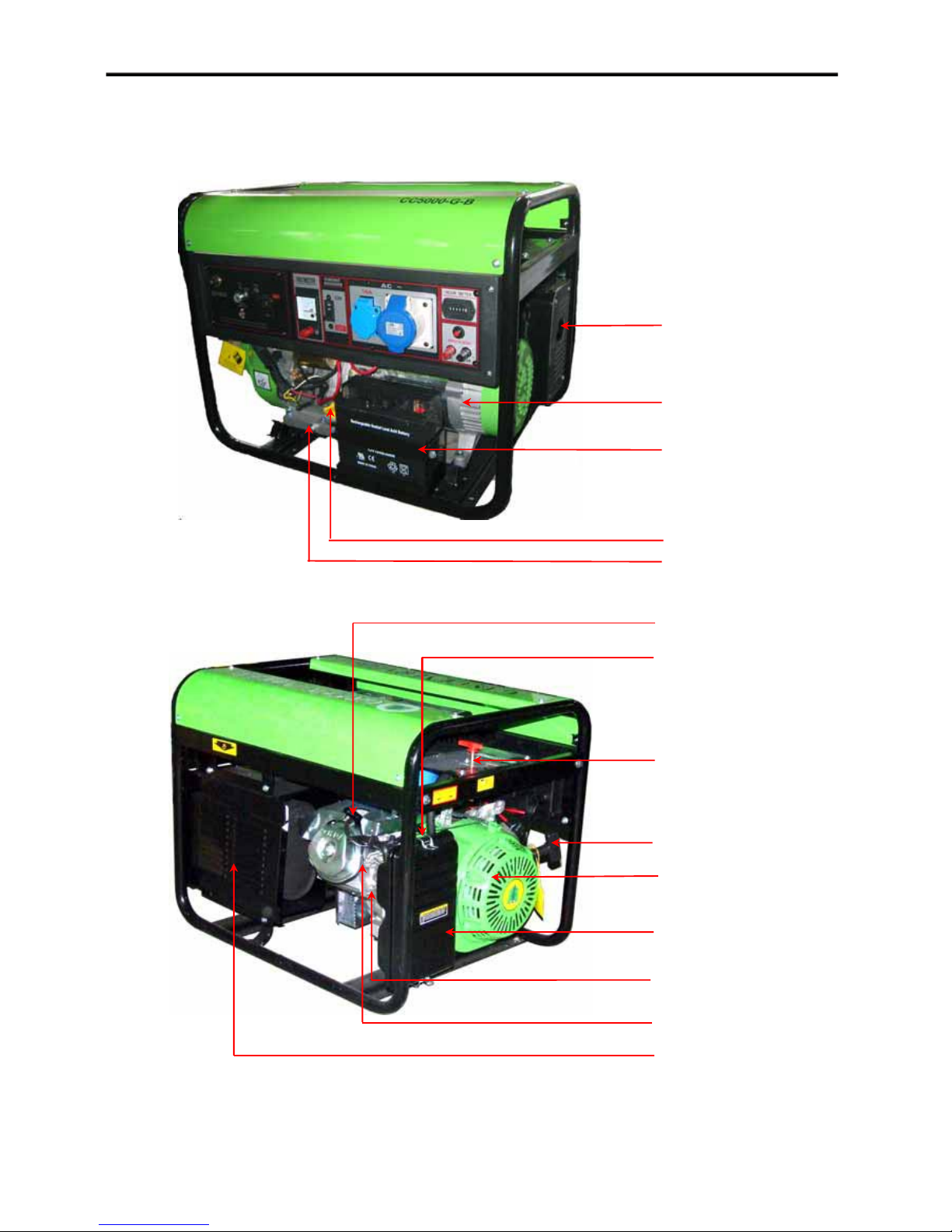
Frame Type :
1. Exhaust Outlet
2. Alternator
3. Battery
4. Oil Filter Cap/Dipstick
5. Oil Drain Plug
6. Spark Plug Cap
7. Choke Grip
8. Engine Switch
9. Recoil Starter Grip
10. Starter Plate
11. Air Filter
12. Mixer
13. Engine
14. Muffler Mantle
4
Page 6
Portable Type:
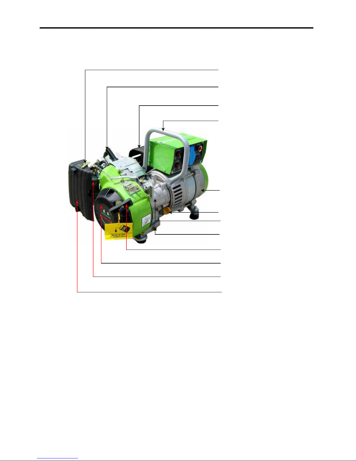
1. Choke Grip
2. Spark Plug Cap
3. Muffler
4. Portable Handle
5. Alternator
6. Oil Filter Cap/Dipstick
7. Engine
8. Oil Drain Plug
9. Recoil Starter Grip
10. Starter Plate
11. Mixer
12. Air Filter
5
Page 7
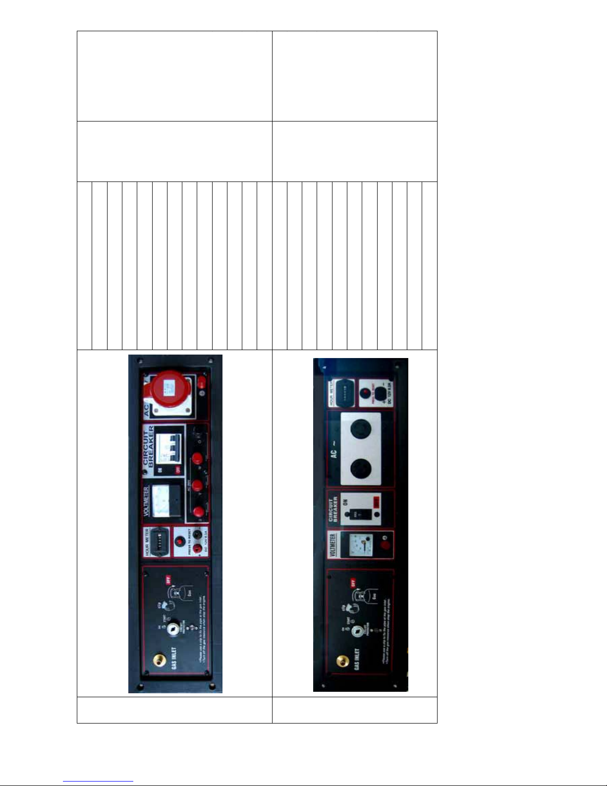
Remark
A
Typ e
Applicable
CC1200
panel
Single Voltage
(Single-phase)
without Hour
Meter(recoil)
CC1200 Single Voltage
(Single-phase ǃ
recoil) for portable
type
Single Voltage
(Single-phase)
with Hour Meter
˄Electric Starter˅
CC3000
CC4000
CC5000
6
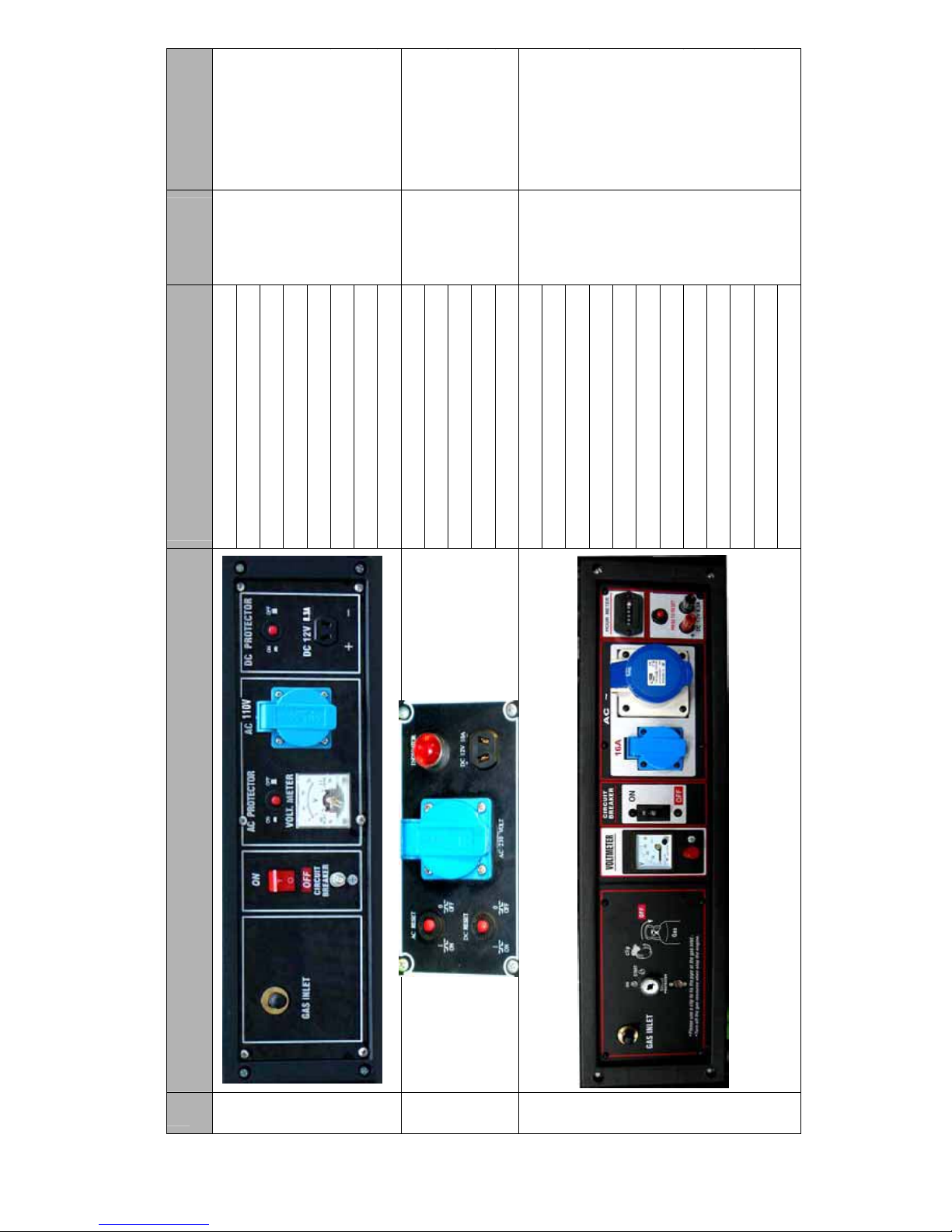
A. Gas Inlet
B. Circuit Breaker
C. Ground Terminal
G
D. AC Overload Protector
E. AC Voltmeter
F. AC Receptacle
G. DC Overload Protector
H. 12V DC Receptacle
H
D
B
EF
C
A. AC Overload Protector
B. DC Overload Protector
C. Receptacle
D. Power Indicator
D
E
E. 12V DC Receptacle
A. Gas Inlet
B. Keyed Ignition
C
B
C. Circuit Protector
D. AC Volt Meter
E. Ground Terminal
F. Circuit Breaker
G. AC Receptacle
H. AC Receptacle
I
J
E
I. Hour Meter
J. DC Overload Protector
K. DC Red Terminal
L. DC Black Terminal
L
H
G
F
No. Power panel Electrical element on control
1
Power Panel List
B
C
2
3
Page 8
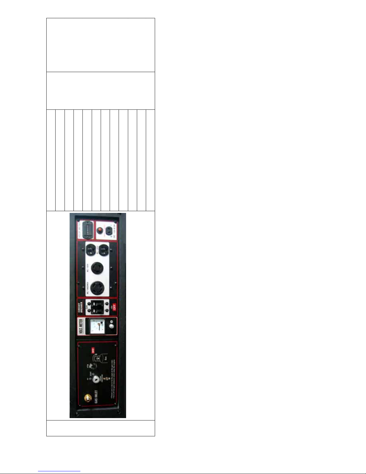
Dual voltage
A
CC3000 ǃ
˄ Three-phase ˅
CC4000 ǃ
with DC Terminal
and Hour Meter
CC5000
Single voltage
CC3000ǃ
˄ Single-phase ˅
CC4000ǃ
with Hour Meter
˄Electric Starter˅
CC5000
7
A. Gas Inlet
B. Keyed Ignition
C. Circuit Protector
D. Hour Meter
E. DC Overload Protector
F. DC Red Terminal
G. DC Black Terminal
H. AC Volt Meter
I. AC Red Terminal
J. Circuit Breaker
K. AC Black Terminal
L. AC Receptacle
L
M
J
K
I
H
G
D
E
A. Gas Inlet
M. Ground Terminal
B. Keyed Ignition
C. Circuit Protector
D. AC Volt Meter
E. Ground Terminal
F. Circuit Breaker
I
D
G. AC Receptacle
H. AC Receptacle
I. Hour Meter
J. DC Overload Protector
J
K
H
FG
K. 12V DC Socket
B
4
5
Page 9
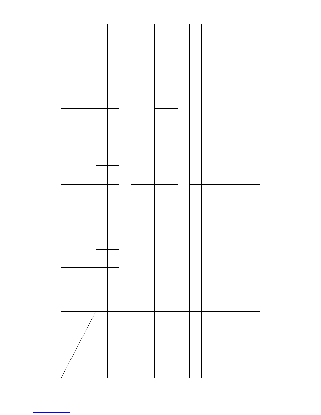
Dual voltage
A
˄Single-phase˅
with Hour Meter
CC3000 ǃ
CC4000 ǃ
CC5000
8
˄Electric Starter˅
A. Gas Inlet
B. Keyed Ignition
C. Circuit Protector
D. AC Volt Meter
E. Ground Terminal
F. Circuit Breaker
G. AC Receptacle
H. AC Receptacle
L
I
G
I. AC Receptacle
J. Hour Meter
K. DC Overload Protector
L. 12V DC Socket
6
Page 10
CC2000-NG
CC2000-G
/kW·h
3
9
CC2000-LPG
CC1500-G
CC1500-NG
CC1500-LPG
CC1200-G
CC1200-NG
DC˖12V/8.3A
CC168F-NG/
Single-Phase Synchronous Brush Alternator
Alternator
CC168F-LPG CC168F-NG/G
G
Recoil StarterǃRecoil/Electric Starter
/kW·h LPG˖0.34kg/kW·h NG˖0.36m
3
81 163
52×38 68×45
0.35 0.55
50 60 50 60 50 60 50 60 50 60 50 60 50 60
CC700-LPG/NG CC1200-LPG
Type
Rated Frequency˄Hz˅
Item
Main Technical Specification and Data Table 1
0.55 0.65 0.8 0.9 0.7 0.8 1.4 1.5 1.3 1.4 1.8 1.9 1.7 1.8
DC Voltage/Current
Rated Output Power˄kW˅
CC152F-LPG CC152F-NG/G CC168F-LPG
Single-Phase Synchronous Brush/Brushless
Power Code
Power Type Single Cylinder, 4-stroke, OHV, Forced Air-cooled
Generator Mode
Displacement˄CC˅
BorehStroke˄mm˅
Starting Mode Recoil Starter
LPG˖0.45kg/kW·h NG˖0.50m
(Rated Power)
Fuel Consumption
Lube Oil Capacity˄L˅
Page 11

CC5000-G
CC5000-NG
CC50000-LPG
/kW·h
3
10
CC4000-G
CC4000-NG
CC40000-LPG
CC3000-G
CC3000-NG
CC3000-LPG
50 60 50 60 50 60 50 60 50 60 50 60
2.8 3.0 2.6 2.7 3.7 3.8 3.4 3.8 4.6 4.7 4.2 4.5
DC˖12V/8.3A
/kW·h LPG˖0.32kg/kW·h NG˖0.35m
Recoil StarterǃRecoil/Electric Starter
270 337 389
77×58 82×64 88×64
3
0.9 0.9 0.9
LPG˖0.33kg/kW·h NG˖0.35m
Model
Main Technical Specification and Data Table 2
Item
Rated Frequency˄Hz˅
DC Voltage/Current
Rated Output Power˄kW˅
Power Code CC177F-LPG CC177F-NG/G CC182F-LPG CC182F-NG/G CC188F-LPG CC188F-NG/G
Generator Mode Single-Phase Synchronous Brush Alternator Single-Phase/Three-Phases Synchronous Brush Alternator
Power Type Single Cylinder, 4-stroke, OHV, Forced Air-cooled
BorehStroke˄mm˅
Starting Mode
Displacement˄CC˅
(Rated Power)
Fuel Consumption
Lube Oil Capacity˄L˅
115V/230Vǃ120V/240V
Remark: 1˅ Rated Output Voltage˄50Hz˅: 220Vǃ230Vǃ240Vǃ380Vǃ220V/380Vǃ230V/400Vǃ240V/415V˗˄60Hz˅: 110Vǃ115Vǃ120Vǃ110V/220Vǃ
2˅ Power Factor(cosij): For three-phase generator cosij=0.8; others cosij=1.
Page 12
Running Condition
Environment Requirement
ķTemperature˖
for NG powered generator set: -30℃40 ;
for LPG powered generator set: -5℃40℃.
ĸ Height above sea level: below 2,000m.
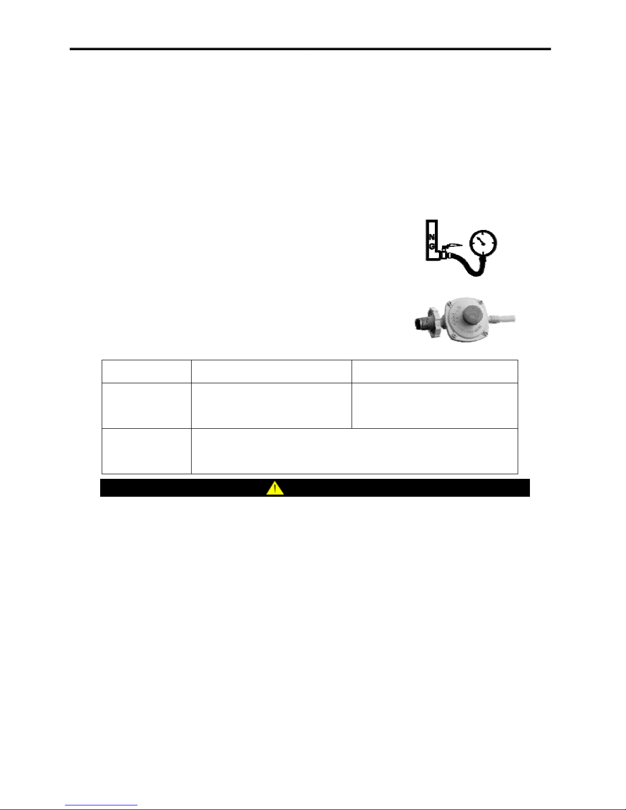
Gas Requirement
NG Powered Generator Set
Recommended gas pressure: 2.06.0 kPa( 0.290.87 psi).
Main Gas Valve should be equipped on main gas pipe.
LPG Powered Generator Set
LPG Pressure Regulator should be equipped on LPG-bottle.
Regulator outlet pressure should be as follow:
℃
Type
CC1200-LPG CC2000-LPG CC3000-LPG CC5000-LPG
Q
m-LPG
1.1Kg/h
Q
m-LPG
2.0Kg/h
Flow rate
Q
V-NG
1.2m3/h
Q
V-NG
2.5m3/h
Regulator outlet
2.5 kPa 3.2 kPa(0.360.46 psi)
pressure
NOTICE
Out of the range may lead to abnormal running even damage of generator set.
11
Page 13
Operation
ƽ
ƽ
ƽ
ƽ
Pre-start Preparation
Generator Location
CAUTION
This generator must have at least five feet of clearance from combustible material.
Leave at least three feet of clearance on all sides of the generator to allow for adequate cooling,
maintenance and servicing.
Place the generator in a well-ventilated area.
DO NOT place the generator near vents or intakes.
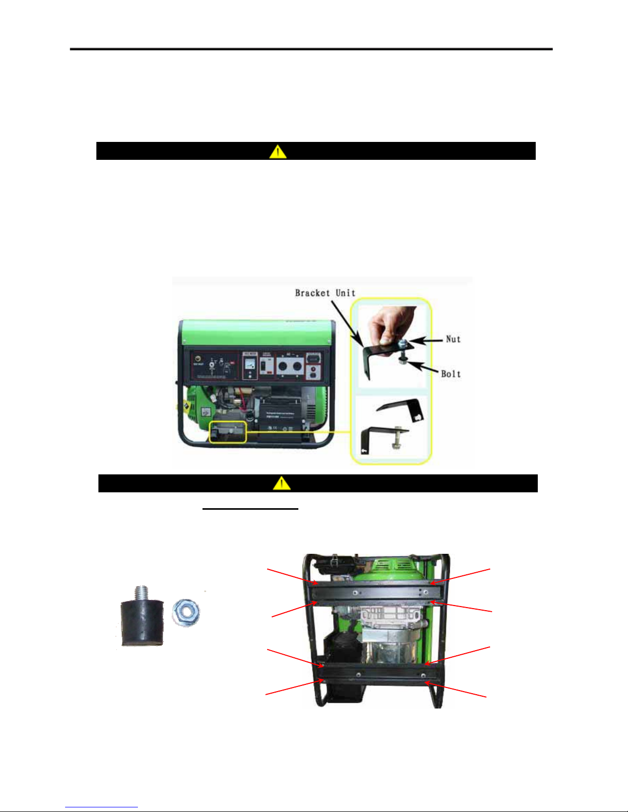
Remove tightening brackets
I
CAUTION
Be sure to remove the tightening brackets
Install the Support Leg (only for CC1500~CC5000 frame type generator sets)
1
2
3
4
Attach the support leg to the generator frame with cap screw(M8×30) and lock nut(M8) at the
position 1~8.
before operating the generator set.
5
6
7
8
12
Page 14
Add Engine Oil
˖
˖
(+)
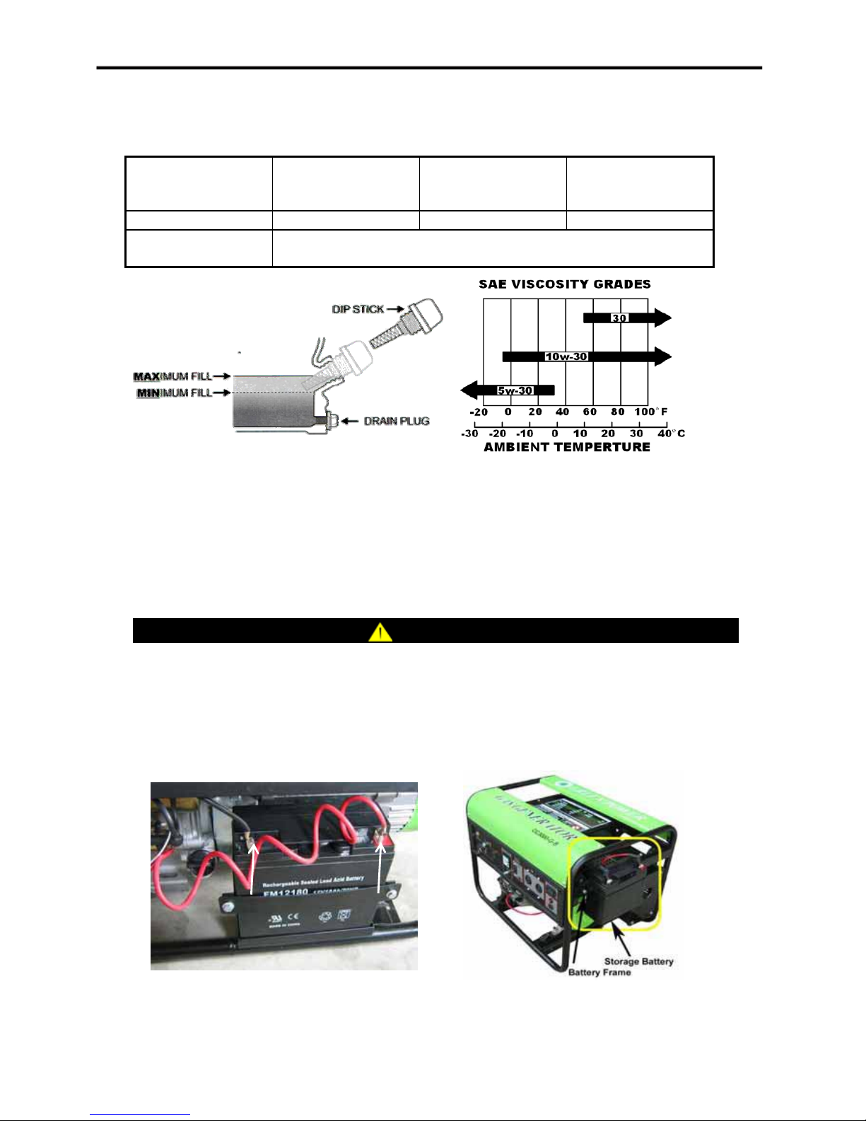
DO NOT attempt to crank or start the engine before it has been properly filled with the
recommended type and amount of oil.
Model CC500
CC700
CC1200
CC1500
CC2000
CC3000
CC4000
CC5000
Oil Capacity 0.35L 0.55L 0.90L
Lube Oil Type SAE5W-30 (Ambient Temperature < 4℃)
SAE10W-30 (Ambient Temperature > 4℃)
Connect Generator to Gas Supply Source
1. Keep the main gas valve closed and “Engine Switch” on “off” position.
2. Embed two clips on the two ends of approved gas pipeline.
3. Attached the gas pipeline to the gas inlet and gas supply source.
4. Use plus driver to tighten the clips on the ends of gas pipeline until it’s not easy to pull down from
gas pipeline.
CAUTION
All gas pipe joints should be fixed by clips tightly.
Connect the Storage Battery
For the Generator Set with Electric Starter, you need to connect the battery as follow:
For CC4000,CC5000
Black
Negative
(-)
For CC1500,CC2000 and CC3000
Red
Positive
Attach the red lead to the red terminal (positive, +) on the battery with the cap screw.
Attach the black lead to the black terminal (negative, -) on the battery with the cap screw.
13
Page 15
Grounding
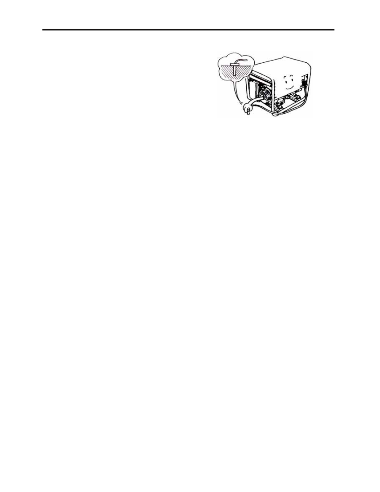
Your generator must be properly connected to an
appropriate ground to help prevent electric shock.
We strongly recommend that you consult with a qualified
electrician to ensure compliance with local electrical
codes.
14
Page 16
Starting the Engine
CAUTION
Disconnect all electrical loads from the generator before starting the engine.
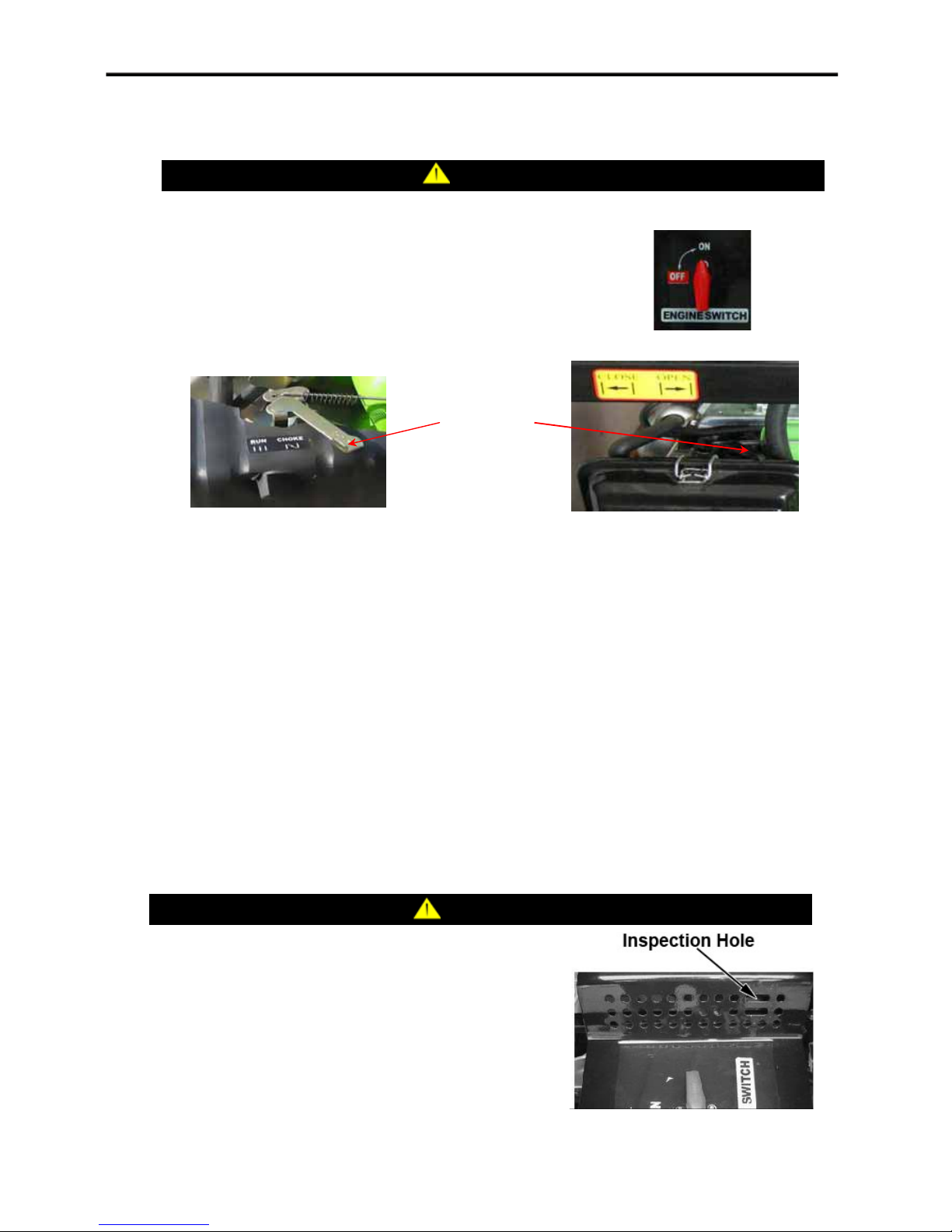
1. Open the Main gas valve.
2. Turn the Engine Switch to the “On” position.
Note: There is no this operation for portable generator set.
3. Move the Choke Grip to the “Choke” or “Close” position.
Choke Grip
4. Start the engine.
For recoil start :
˄1˅Pull the Starter Grip slowly until resistance is felt and then pull rapidly.
˄2˅After the engine started, return the Starter Grip gently to prevent damage to the starter or
housing.
For electric start :
Turn the Keyed Ignition to the “Start” position and hold until engine starts. If the engine fails to
start within five seconds, release the key and wait at least 5 seconds before attempting to start the
engine again.
Note: this operation only for generator set with electric starter.
5. As engine warms up, move the Choke Grip to “Run” or “Open” position.
NOTICE
if your engine is starting, do a inspection on the top cooling
fan˄if the fan is installed in your generator˅, and ensure it is
operating. Otherwise, you should shut down the engine.
15
Page 17
Connecting Electrical Loads
ƽ
ƽ
ƽ
Let the engine stabilize and warm up for a few minutes after starting.
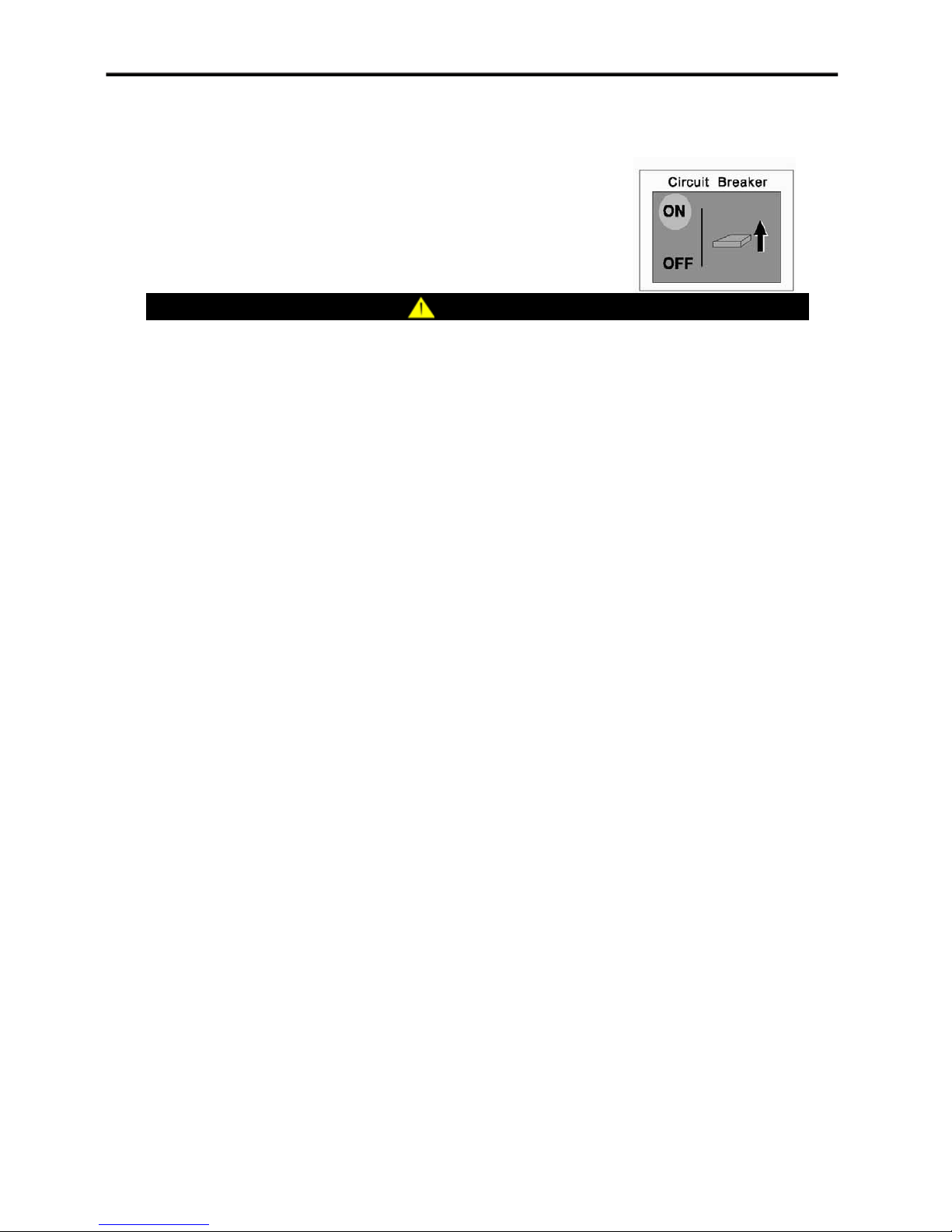
1. Plug in and turn on Circuit Breaker from “OFF” to “ON” position.
2. Turn on the desired electrical loads.
WARNING
DO NOT overload the generator.
DO NOT use parallel with any other generators.
Connection to the household electrical system must be made by a qualified electrician.
Stopping the Engine
1. Turn off and unplug all electrical loads. Never start or stop the generator with electrical devices
plugged in or turned on.
2. Let the generator run at no-load for several minutes to stabilize.
3. Turn the Engine Switch to the “Off” position.
4. Turn off the Main gas valve.
Do Not Overload Generator Capacity
Follow these simple steps to calculate the running and starting watts necessary for your purposes.
1. Select the electrical devices you plan on running at the same time.
2. Total the running watts of these items.
This is the amount of power you need to keep your items running.
3. Identify the highest starting wattage of all devices identified in step 1. Add this number to the
number calculated in step 2. Surge wattage is the extra burst of power needed to start some electric
driven equipment. Following the steps listed under “Power Management” will guarantee that only
one device will be starting at a time.
Power Management
Use the following formula to convert voltage and amperage to watts:
Volts × Amps = Watts
To prolong the life of your generator and attached devices, follow these steps to add electrical load:
1. Start the generator with no electrical load attached.
2. Allow the engine to run for several minutes to stabilize.
3. Plug in and turn on the first item. It is best to attach the item with the largest load first.
4. Allow the engine to stabilize.
5. Plug in and turn on the next item.
6. Allow the engine to stabilize.
7. Repeat steps 5-6 for each additional item.
Note: Never exceed the generator capacity when adding loads.
16
Page 18
Wattage Reference Chart
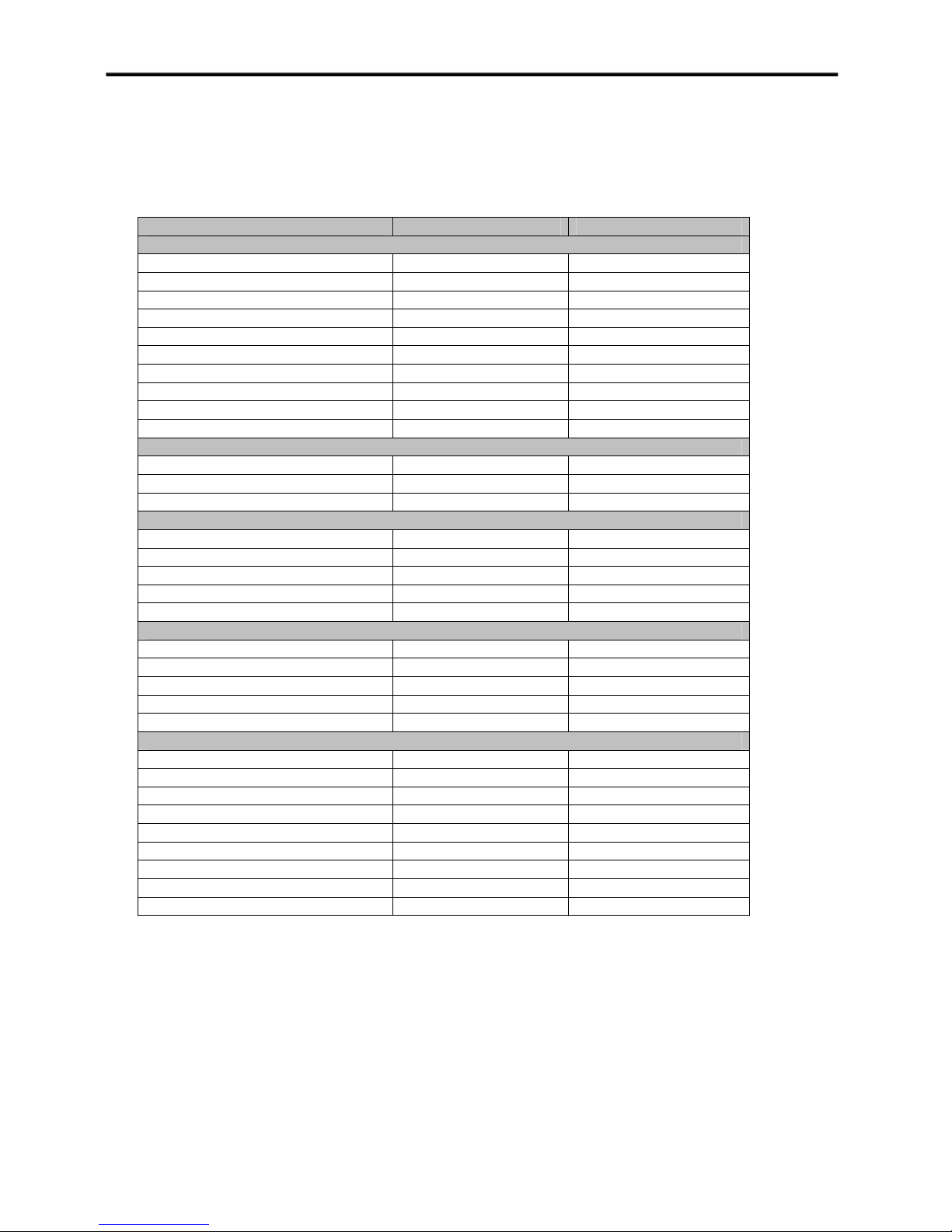
Use the chart to determine approximate wattage requirements for your equipment.
Note: Starting watts can exceed three times the running watts.
The values in the following table are approximate. Refer to your tool or appliance for actual wattage
consumption.
Item Running Watts Starting Watts
Essentials
Light bulb 100W 100W 0
Refrigerator / Freezer 1200W 2400W
Freezer 500W 500W
Sump Pump 600W 1800W
Well Pump 1HP 2000W 4000W
Water Heater 4000W 0
Security System 180W 0
AM / FM Radio 300W 0
Garage Door Opener 1/2HP 500W 600W
Battery Charger 12V DC 110W 0
Heating / Cooling
Air Conditioner 12000 BTU 1700W 2500W
Fan 300W 600W
Furnace Fan 1/3 HP 1200W 2000W
Home Appliances
Microwave 1000W 1000W 0
Electric range – one element 1500W 0
Electric skillet 1250W 0
Coffee Maker 1500W 0
Clothes Washer 1200W 0
Entertainment
CD / DVD Player 100W 0
VCR 100W 0
Stereo Receiver 450W 0
Television 27” 500W 0
PC with 15” Monitor 800W 0
Job Site
Belt Sander 3” 1000W 1500W
Bench Grinder 6” 700W 1500W
Circular Grinder 1500W 1500W
Compressor 1 1/2 HP 2500W 2500W
Edge Trimmer 500W 500W
Hand Drill 1/2” 1000W 1000W
Lawn Mower 1200W 1800W
Paint Sprayer 600W 1200W
Table Saw 2000W 2000W
17
Page 19

Maintenance
ƽ
ƽ
ƽ
ƽ
ƽ
MAINTENANCE IMPORTANCE
Complete all scheduled maintenance in a timely manner. Correct any issue before
operating the generator.
Improper maintenance will void your warranty. Tampering with the factory set governor
will void your warranty.
To ensure the best quality, use only genuine “Green Power” parts or their equivalents for
repair or replacement.
MAINTENANCE SAFETY
Read the instructions before you begin, and make sure you have the tools and skills
required.
Always follow the procedures and maintenance instructions in the owners manual.
WARNING
18
Page 20
Engine Maintenance
To prevent accident happening, remove and ground spark plug wire before performing any service.
Engine Oil
Change oil when the engine is warm. Refer to the oil specification to select the proper grade of oil
for your operating environment.
1. Remove the oil drain plug.
2. Allow the oil to drain completely.
3. Reinstall the oil drain plug.
4. Remove oil fill cap/dipstick to add oil.
5. Add engine oil according to specification and reinstall oil fill cap/dipstick.
CAUTION
Change engine oil after the first 20 running hours. Check engine oil level before every use.
Spark Plug
1. Remove the spark plug cable from the spark plug.
2. Use the spark plug tool that shipped with your generator to remove the plug.
3. Inspect the electrode on the plug. It must be clean and not worn to produce the spark required for
ignition.
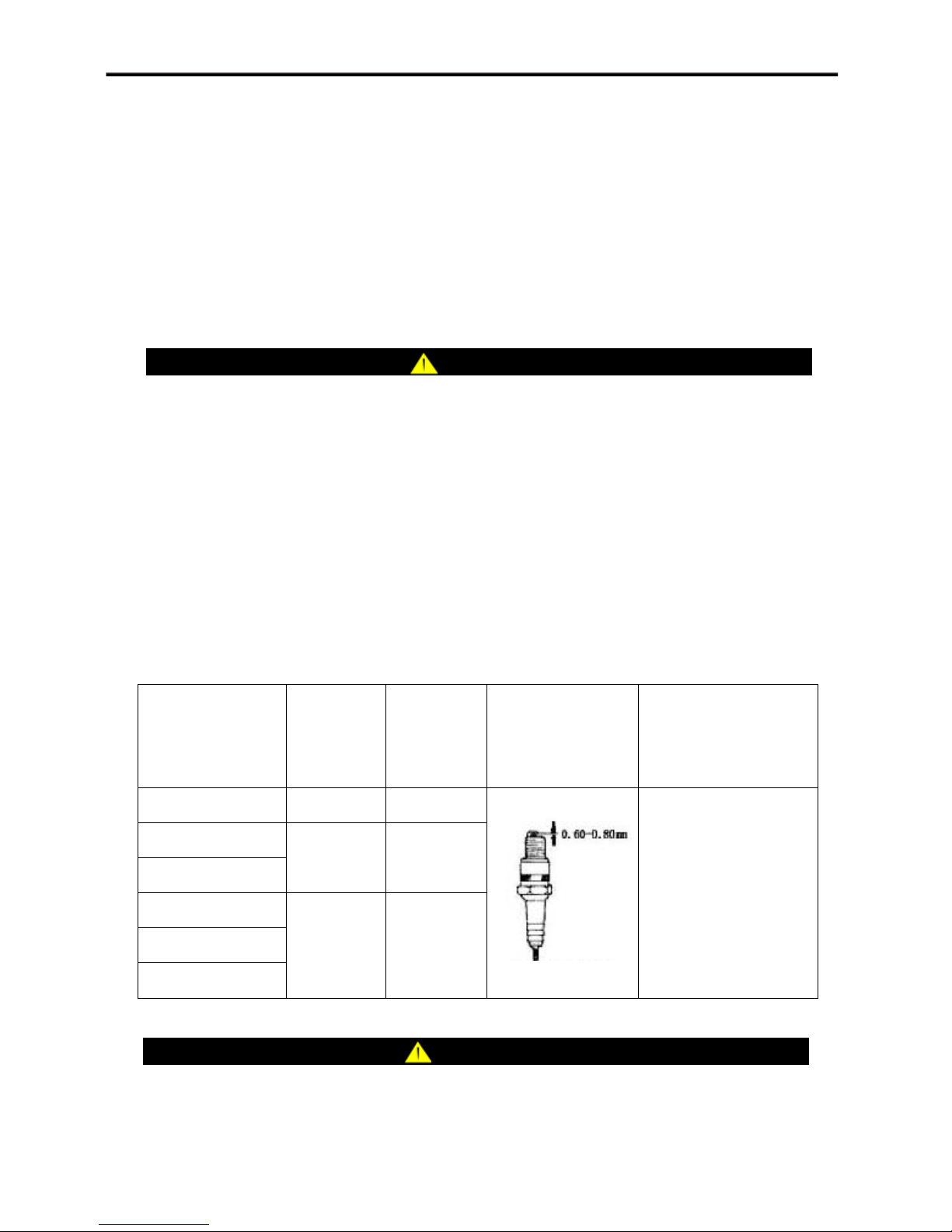
4. Make certain the spark plug gap as follow table.
5. Refer to below table when replacing the plug.
6. Carefully thread the plug into the engine.
7. Use the spark plug tool to firmly install the plug.
8. Attach the spark plug wire to the plug.
Inlet/Outlet Valve Clearance and Spark Plug Gap
Item
CC1200-NG/LPG
CC1500-NG/LPG
CC2000-NG/LPG
CC3000-NG/LPG
CC4000-NG/LPG
CC5000-NG/LPG
Inlet Valve
Clearance
˄cold˅
0.20˄mm˅ 0.25˄mm˅
0.06~0.08
˄mm˅
0.06~0.08
˄mm˅
Outlet Valve
Clearance
˄cold˅
0.08~0.10
˄mm˅
0.08~0.10
˄mm˅
Spark Plug Screwing
Spark Plug Gap
Moment
18~20˄N·m˅
CAUTION
Note: Allow the engine to cool before removing the spark plug. Otherwise, it will be damaged.
19
Page 21
Air Filter
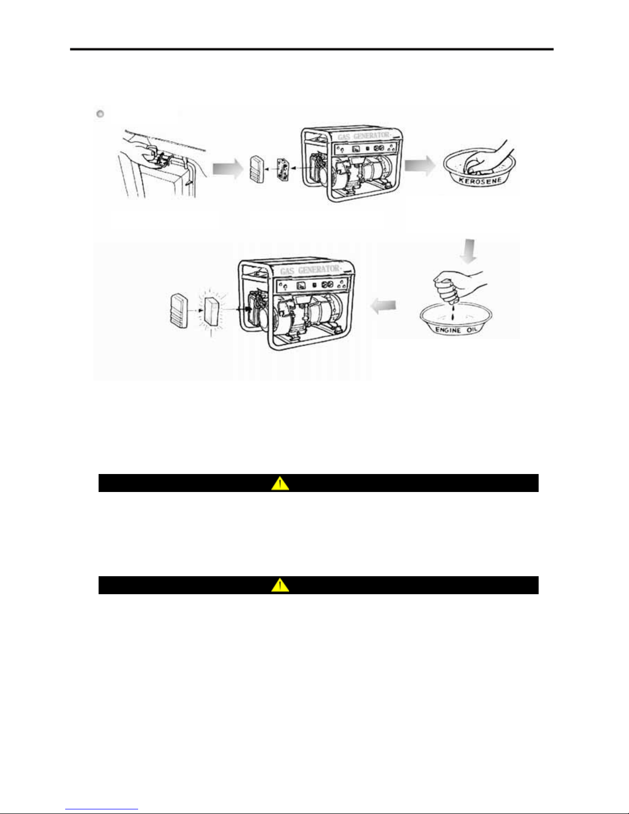
Clean air filter as follow chart:
Clean Air Filter
Open the air filter cover Dispart the sponge of air filter
Wash the sponge by kerosene
or gasoline, then dry it
Soak the sponge in engine oil,
then squeeze the engine oil out
from the sponge
Air-fuel Mixer
The air-fuel mixer is not adjustable. Tampering with the governor can damage your generator and
your electrical devices and will void your warranty.
WARNING
Disassemble Air-fuel Mixer will void your warranty in the first 300 running hours. Please
contact authorized agent if you need change Air-fuel Mixer.
Cleaning
CAUTION
DO NOT spray engine with water.
Water can contaminate the fuel system.
Use a damp cloth to clean exterior surfaces of the engine.
Use a soft bristle brush to remove dirt and oil. Use an air compressor (25 PSI) to clear dirt and
debris from the engine.
Inspect all air vents and cooling slots to ensure that they are clean and unobstructed.
20
Page 22
Generator Maintenance
Make certain that the generator is kept clean and stored properly.
Only operate the unit on a flat, level surface in a clean, dry operating environment.
DO NOT expose the unit to extreme conditions, excessive dust, dirt, moisture or corrosive vapors.
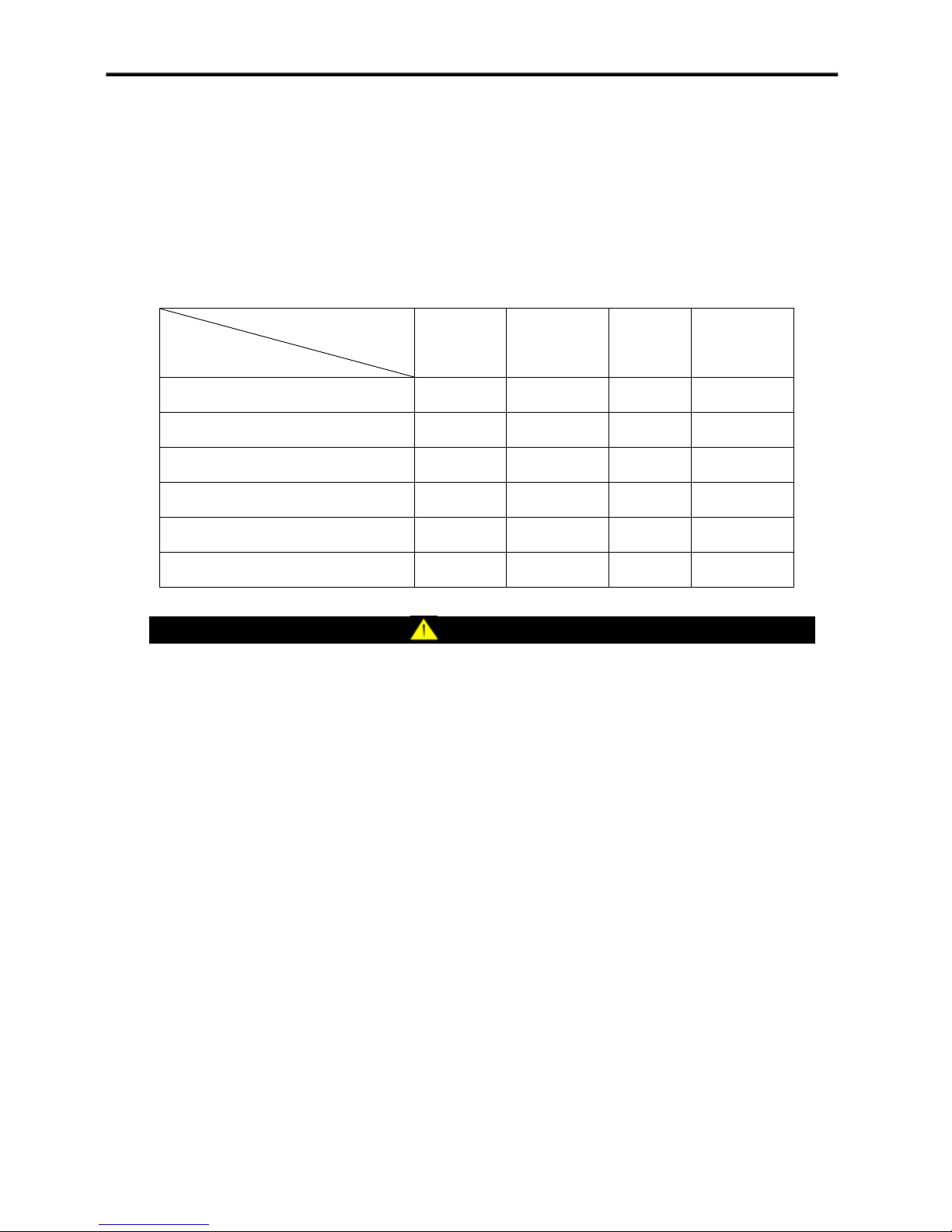
Maintenance Schedule
Follow the service intervals indicated in the schedule below.
Parts Maintenance Schedule
Total runtime
50 Hrs 100 Hrs 200 Hrs 300 Hrs
Item
Change lube oil Ɣ
Clean the sponge of air filter Ɣ
Check or change spark plug Ɣ
Check gas hose Ɣ
Clean the residue in the chamber Ɣ
Clean generator set Ɣ
NOTICE
Service your generator more frequently when operating in adverse conditions.
21
Page 23
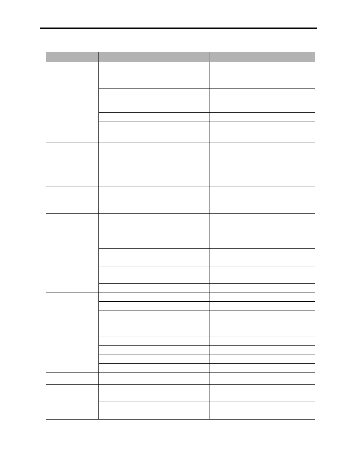
Common Breakdowns and Troubleshooting
Trouble Cause Solution
Fail to start
Generator starts
but runs roughly
or frequency
fluctuating
obviously
down during
operation
Generator can not
supply enough
power or
overheating
No AC output
Battery not connected or connected
wrongly
Connect the battery correctly
Battery not charged Recharge or replace battery
No gas Open gas main valve
Faulty spark plug Replace spark plug
Unit loaded during start up Remove load from unit
Low engine oil level
Fill crankcase to the proper level,
place generator on a flat, level surface
Choke in the wrong position Adjust choke
Air-fuel ratio changes acutely
Replace air-fuel mixer or contact
authorized agent
No gas Replace gas supply source Generator shuts
Low engine oil level
Generator is overloaded
Gas pressure is out of range
High ambient temperature causes gas
density reducing
Running under low ambient temperature
causes lower gas evaporation
Fill crankcase to the proper level,
place generator on a flat, level surface
Review load and adjust. See” Power
Management”
Change gas supply source or contact
authorized agent
Adjust choke
Adjust choke
Fuel gas components changing Adjust choke
Cable not properly connected Check all connections
Connected device is defective Replace defective device
AC circuit breaker is off
Adjust load and reset AC circuit
breaker
Capacitor defective Replace capacitor
Faulty brush assembly Replace brush assembly
Faulty AVR Replace AVR
Loose wiring Inspect and tighten wiring connections
Others Contact authorized agent
Generator gallops Engine governor defective Contact authorized agent
Repeated circuit
breaker tripping
Overload
Faulty cords or device
22
Review load and adjust. See” Power
Management ”
Check for damaged, bare or frayed
wires. Replace defective device
Page 24

Storage
The generator should be started at least once every 14 days and allowed to run for at least 20
minutes. For longer term storage, please follow these guidelines.
Engine Storage
1. Allow the engine to cool completely before storage.
2. Clean the engine according to the instructions in the Maintenance section.
3. Turn the “Engine Switch” off on the generator.
4. Close the manual shutoff valve on the LPG cylinder or on the NG pipeline and disconnect from
the generator.
5. Drain all the oil.
6. Remove the spark plug and pour about ½ ounce of oil into the cylinder. Crank the engine slowly
to distribute the oil and lubricate the cylinder.
7. Reattach the spark plug.
Generator Storage
1. Allow the generator to cool completely before storage.
2. Clean the generator according to the instructions in the Maintenance section.
3. Store the unit in a clean, dry area, out of direct sunlight.
Transportation
Drain all remained oil in the crankcase.
Package generator set according factory state.
CAUTION
Never lay the generator set with upside down.
23
Page 25
Accessory
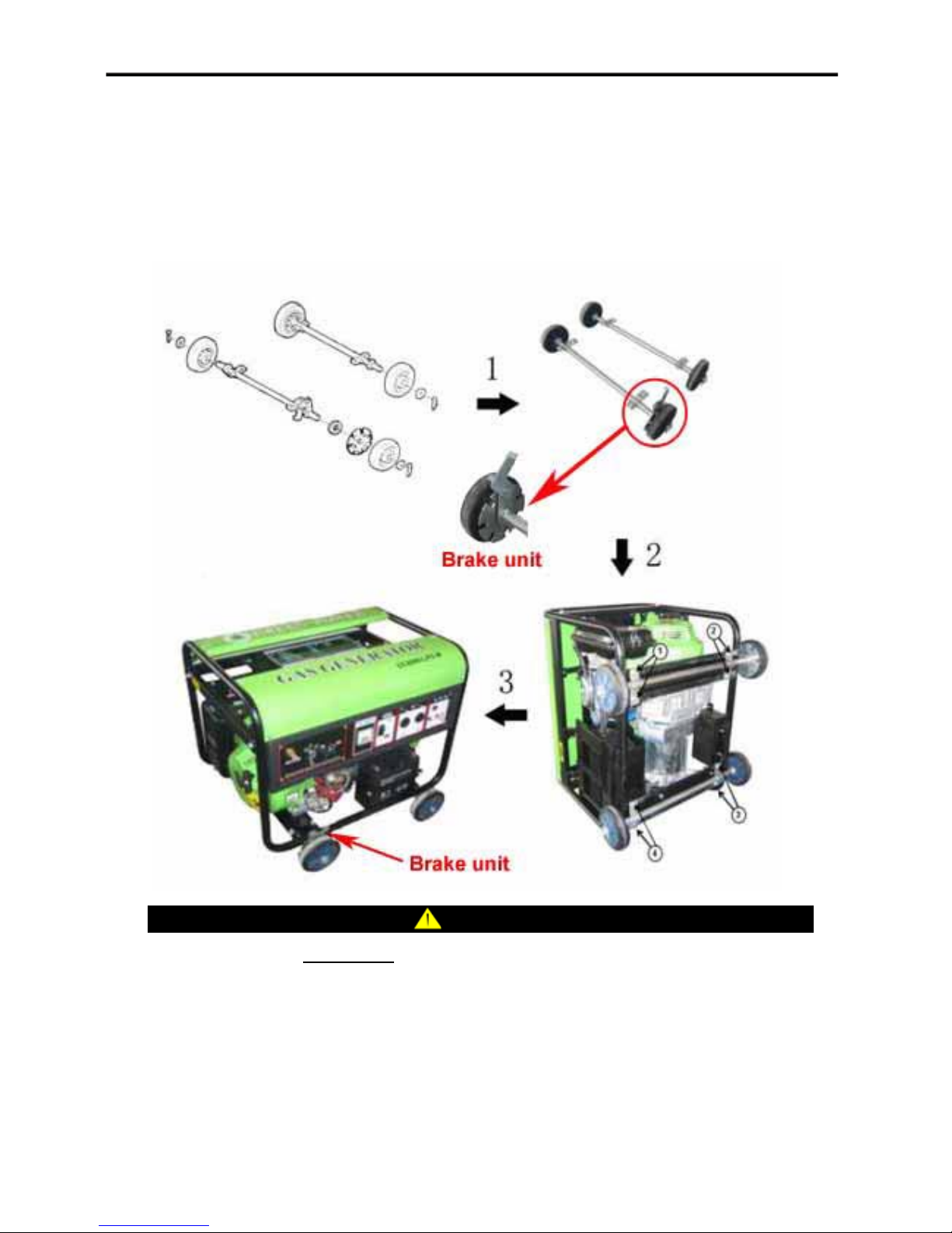
How to install four-wheel generator set
1ǃ Install the wheelsǃwashersǃpins and brake unit on the two axles separatelyDŽ
2ǃ Fix the wheel kit with bolts at position 1~4DŽ
Be sure to use the Brake unit to hold the generator set.
NOTICE
24
Page 26
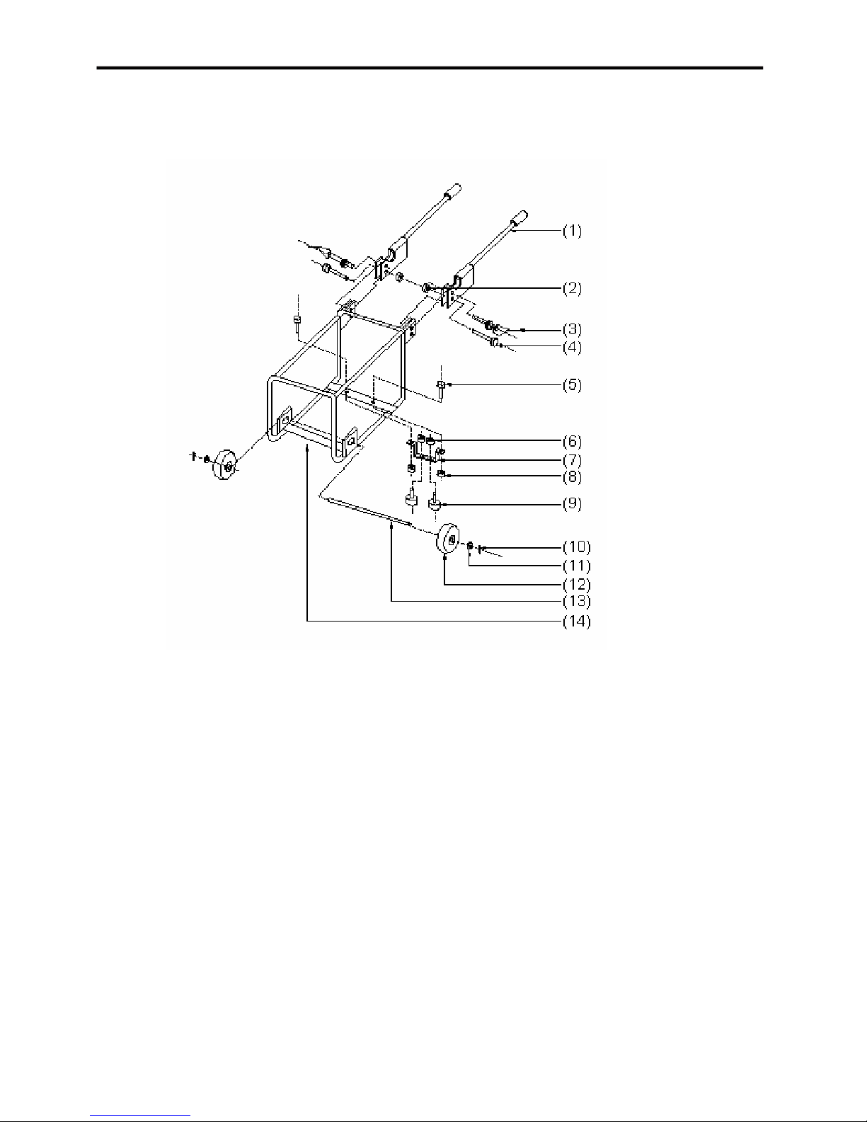
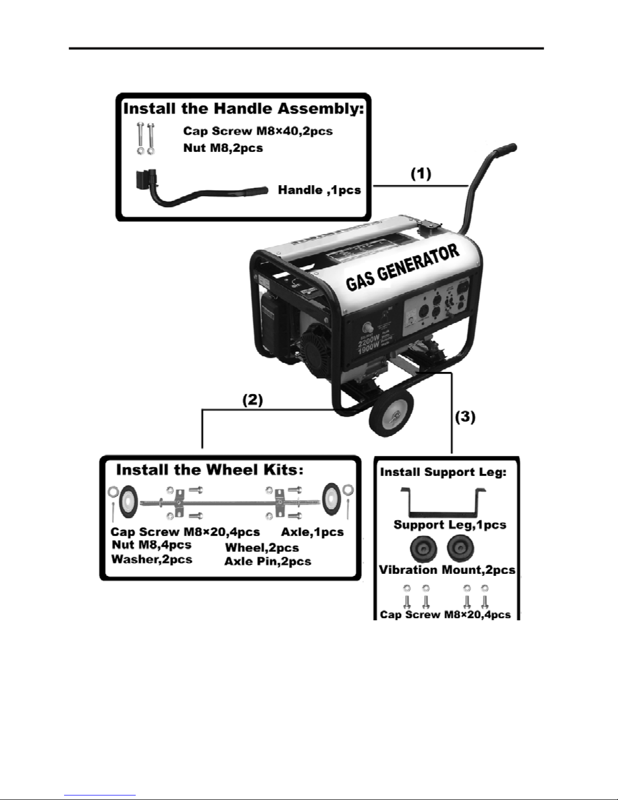
How to install two-wheel (CC3000/4000/5000) generator set
Installation schematic drawing as follow:
1—Handle 2—Nut M8 3—Spring Pin with Nylon Rope 4—Bolt M8×45
5—Bolt M8×16 6—Nut M8 7—Supporting Bracket 8—Nut M8
9—Supporting Leg 10—Cotter Pin 11—Locked Spacer 12—Pneumatic Tyre
13—Axle 14—Bracket
Note: Pneumatic pressure in the tyre is 140~160 kPa.
25
Page 27
How to install two-wheel (CC1500/2000) generator set
26
Page 28
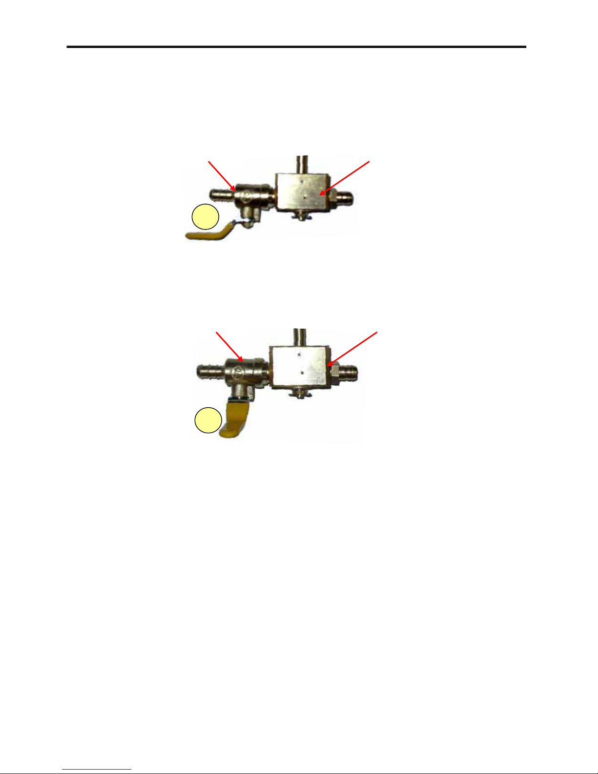
How to operate dual fuel (NG/LPG) generator set
Use NG (Nature Gas)
Please turn the fuel switch at Position 1.
Fuel Switch Engine Switch
1
Use LPG (Liquefied Petroleum Gas)
Please turn the fuel switch at Position 2.
Fuel Switch Engine Switch
2
27
Page 29
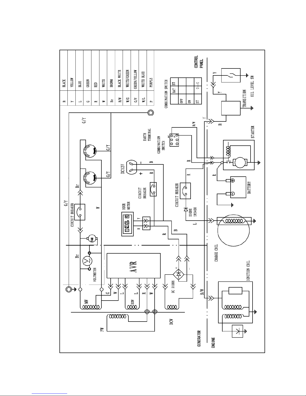
28
CC3000/4000/5000 single voltage generator (with electric start) circuit diagram
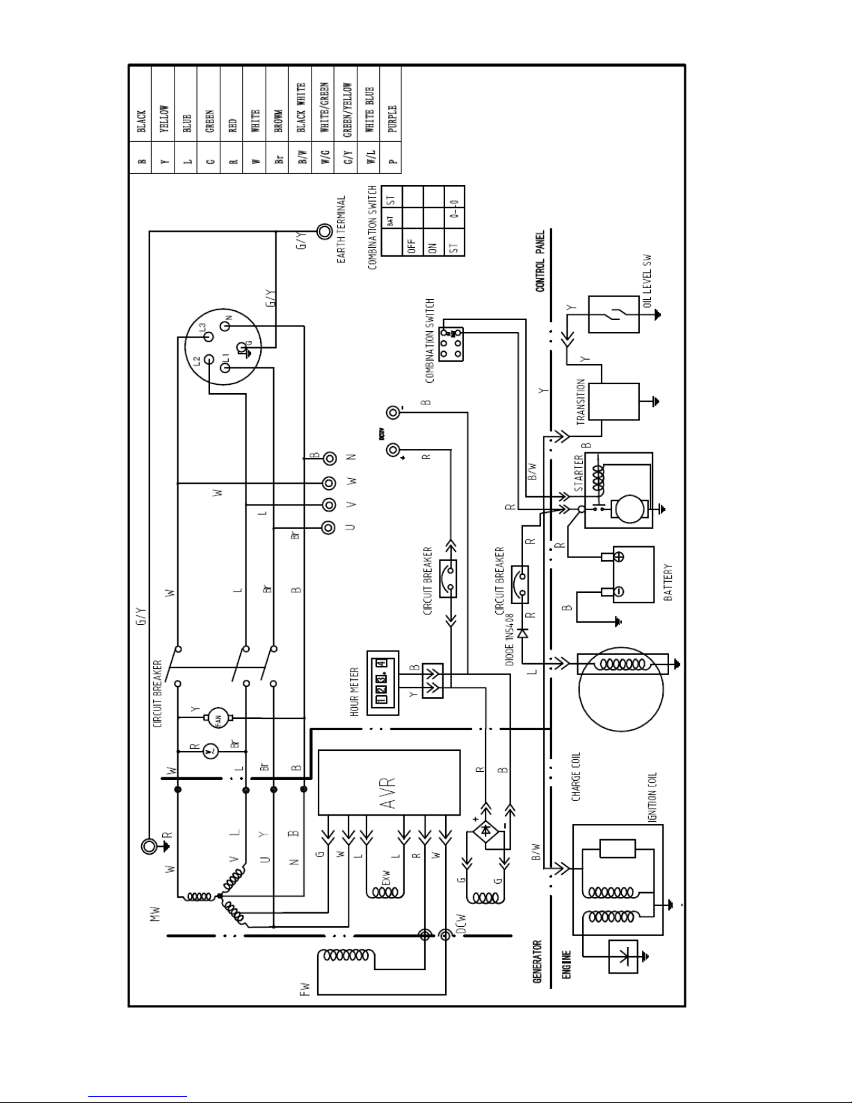
Generator Circuit Diagram
Page 30
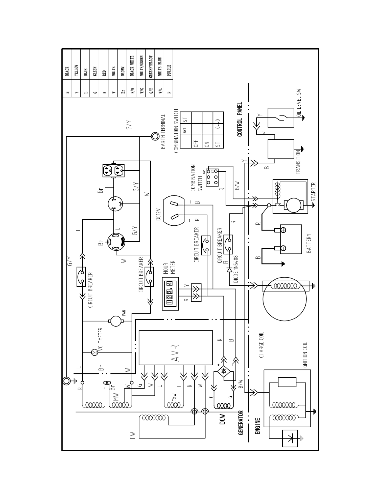
29
CC3000/4000/5000 dual voltage generator (with electric start) circuit diagram
Page 31
30
CC5000 Three-Phase generator (with electric start)circuit diagram
 Loading...