

Green Packet Berhad OX250 GP User Manual

User Manual
OX-250
WiMAX Outdoor CPE
Version 0.5
Nov. 8 , 2010
This Document may be subject to change, please contact with us for the latest version.
1

Federal Communication Commission Interference St atement
This equipment has been tested and found to comply with the limits for a Class B digital device,
pursuant to Part 15 of the FCC Rules. These limits are designed to provide reasonable
protection against harmful interference in a residential installation. This equipment generates,
uses and can radiate radio frequency energy and, if not installed and used in accordance with
the instructions, may cause harmful interference to radio communications. However, there is
no guarantee that interference will not occur in a particular installation. If this equipment does
cause harmful interference to radio or television reception, which can be determined by turning
the equipment off and on, the user is encouraged to try to correct the interference by one of the
following measures:
- Reorient or relocate the receiving antenna.
- Increase the separation between the equipment and receiver.
- Connect the equipment into an outlet on a circuit different from that to which the receiver
is connected.
- Consult the dealer or an experienced radio/TV technician for help.
FCC Caution: Any changes or modifications not expressly approved by the party responsible
for compliance could void the user's authority to operate this equipment.
This device complies with Part 15 of the FCC Rules. Operation is subject to the following two
conditions: (1) This device may not cause harmful interference, and (2) this device must
accept any interference received, including interference that may cause undesired operation.
IMPORTANT NOTE:
FCC Radiation Exposure Statement:
This equipment complies with FCC radiation exposure limits set forth for an uncontrolled
environment. This equipment should be installed and operated with minimum distance 50cm
between the radiator & your body.
This transmitter must not be co-located or operating in conjunction with any other antenna or
transmitter.
Due to the essential high output power natural of WiMAX device, use of this device with other
transmitter at the same time may exceed the FCC RF exposure limit and such usage must be
prohibited (unless such co-transmission has been approved by FCC in the future).
2

History
Revision
0.1 2010-10-14 First draft IChia Lin.
0.2 2010-10-18 Add specification IChia Lin
0.3 2010/1 0/26
0.4 2010/11/4 Update figure 70 IChia Lin
0.5 2010/11/8 Change min.35cm distance to 50cm IChia Lin
Date of
Issue
Scope Author
Change min.30cm distance to 35cm,add
install and ground guide
IChia Lin
3

Table of Contents
History ...................................................................................................................................... 3
Table of Contents..................................................................................................................... 4
List of Figures.......................................................................................................................... 6
List of Tables............................................................................................................................ 9
1. Introduction...................................................................................................................11
1.1. Connect..............................................................................................................11
1.2. Logout...............................................................................................................12
1.3. Status ................................................................................................................ 13
1.4. Device Status.................................................................................................... 13
1.5. Setup Wizard .................................................................................................... 15
2. Network.........................................................................................................................20
2.1. LAN.................................................................................................................... 20
2.1.1. IP........................................................................................................... 20
2.1.2. DHCP.................................................................................................... 21
2.2. WAN................................................................................................................... 23
2.2.1. WAN...................................................................................................... 24
2.2.2. DNS ...................................................................................................... 26
2.3. VLAN ................................................................................................................. 28
2.4. DDNS.................................................................................................................29
3. Advanced Setting......................................................................................................... 32
3.1. NAT.................................................................................................................... 32
3.1.1. Port Forward........................................................................................ 32
3.1.2. Port Trigger..........................................................................................34
3.1.3. DMZ ...................................................................................................... 36
3.1.4. ALG ...................................................................................................... 37
3.2. Firewall.............................................................................................................. 38
3.2.1. IP Filter................................................................................................. 38
3.2.2. DOS ...................................................................................................... 40
3.3. Route.................................................................................................................41
3.3.1. Static Route......................................................................................... 41
3.3.2. RIP........................................................................................................43
3.4. UPnP.................................................................................................................. 46
3.4.1. UPnP Setting....................................................................................... 46
3.5. IGMP Proxy.......................................................................................................47
3.5.1. IGMP Proxy Setting............................................................................. 47
3.5.2. VPN Setting ......................................................................................... 48
3.6. PPTP.................................................................................................................. 48
3.6.1. PPTP Server ........................................................................................ 48
3.6.2. PPTP Client.......................................................................................... 51
3.6.3. L2TP ..................................................................................................... 53
3.6.4. L2TP Server......................................................................................... 53
3.6.5. L2TP Client.......................................................................................... 57
3.7. IPSec ................................................................................................................. 59
3.7.1. Connection.......................................................................................... 59
4. WiMAX...........................................................................................................................64
4.1. Profile................................................................................................................64
4.1.1. Connect Settings ................................................................................ 65
4

Frequency Settings............................................................................. 67
4.1.2.
4.1.3. Authentication Settings ..................................................................... 69
4.2. Connect............................................................................................................. 72
4.3. Wide Scan.........................................................................................................73
4.4. Link Status........................................................................................................ 74
4.5. Link Statistics................................................................................................... 75
4.6. Connection Info................................................................................................ 76
4.7. Service Flow ..................................................................................................... 76
5. Administrator ............................................................................................................... 77
5.1. Remote Control................................................................................................ 77
5.1.1. HTTP..................................................................................................... 78
5.1.2. TELNET................................................................................................79
5.1.3. SSH....................................................................................................... 80
5.1.4. SNMP.................................................................................................... 81
5.1.5. TR-069..................................................................................................82
5.1.6. OMA-DM............................................................................................... 84
5.2. Password..........................................................................................................86
6. System..........................................................................................................................88
6.1. Date and Time .................................................................................................. 88
6.1.1. Date ...................................................................................................... 89
6.1.2. Time Zone............................................................................................ 89
6.2. Upgrade Firmware ........................................................................................... 90
6.2.1. Upgrade File........................................................................................ 90
6.2.2. Upgrade Link....................................................................................... 91
6.3. Log..................................................................................................................... 92
6.4. Backup/Restore................................................................................................ 92
6.4.1. Configuration Backup ........................................................................ 92
6.4.2. Configuration Restore........................................................................ 94
6.4.3. Factory Defaults.................................................................................. 95
7. Installing and grounding device................................................................................. 97
Specification ........................................................................................................................ 100
5

List of Figures
Figure 1 Login page....................................................................................................... 12
Figure 2 Logout.............................................................................................................. 12
Figure 3 Status window................................................................................................. 13
Figure 4 Device status................................................................................................... 14
Figure 5 Setup Wizard................................................................................................... 15
Figure 6 Wizard LAN Settings in Setup Wizard .......................................................... 16
Figure 7 WiMAX Frequency Settings By List in Setup Wizard.................................. 17
Figure 8 WiMAX Frequency Settings By Range in Setup Wizard.............................17
Figure 9 WiMAX Authentication Settings in Setup Wizard........................................18
Figure 10 Wizard Save..................................................................................................... 19
Figure 11 Network Topology........................................................................................... 20
Figure 12 Network>LAN>IP............................................................................................. 20
Figure 13 Network>LAN>DHCP...................................................................................... 22
Figure 14 Network>WAN>WAN....................................................................................... 24
Figure 15 Network>WAN>DNS....................................................................................... 26
Figure 16 Network>VLAN................................................................................................ 28
Figure 17 Network>DDNS ............................................................................................... 30
Figure 18 Advanced>NAT>Port Forward.......................................................................33
Figure 19 Advanced>NAT>Port Trigger......................................................................... 34
Figure 20 Advanced>NAT>DMZ...................................................................................... 36
Figure 21 Advanced>NAT>ALG...................................................................................... 37
Figure 22 Advanced>Firewall>IP Filter.......................................................................... 38
Figure 23 Advanced>Firewall>DDOS............................................................................. 40
Figure 24 Advanced>Route>Static Route.....................................................................41
6

Figure 25
Figure 26 Advanced>Route>RIP.................................................................................... 43
Figure 27 Advanced UPnP.............................................................................................. 46
Figure 28 Advanced>IGMP Proxy.................................................................................. 47
Figure 29 VPN>PPTP>Server.......................................................................................... 49
Figure 30 VPN>PPTP>Client........................................................................................... 51
Figure 31 VPN>PPTP>Client>Add.................................................................................. 51
Figure 32 VPN>L2TP>Server.......................................................................................... 54
Figure 33 VPN>L2TP>Client ........................................................................................... 57
Figure 34 VPN>L2TP>Client>Add .................................................................................. 57
Figure 35 VPN>IPsec Overview...................................................................................... 59
Figure 36 VPN>IPsec>Add.............................................................................................. 60
Advanced>Route>Static Route>Add............................................................ 41
Figure 37 Wireless Broadband Access.......................................................................... 64
Figure 38 WiMAX>ProfiIe>Connect Settings ................................................................ 65
Figure 39 WiMAX>Profile>Frequency Settings>By List .............................................. 67
Figure 40 WiMAX>Profile>Frequency Settings>By Range.......................................... 68
Figure 41 WiMAX>ProfiIe>Authenticaton Settings (No Authentication).................... 69
Figure 42 WiMAX>ProfiIe>Authenticaton Settings (User Authentication)................. 70
Figure 43 WiMAX>Connect>Connect ............................................................................ 72
Figure 44 WiMAX>Wide Scan......................................................................................... 73
Figure 45 WiMAX>link Status......................................................................................... 74
Figure 46 WiMAX Link Statistics.................................................................................... 75
Figure 47 WiMAX Connection Info................................................................................. 76
Figure 48 WiMAX Service Flow ...................................................................................... 76
Figure 49 Administration>Remote Control>HTTP........................................................ 78
Figure 50 Administration>Remote Control>Telnet....................................................... 79
Figure 51 Administration>Remote Control>SSH.......................................................... 80
7

Figure 52
Figure 53 Administration>Remote Control>TR-069..................................................... 82
Figure 54 Administration>Remote Control>OMA-DM.................................................. 84
Figure 55 Administrator>Password...............................................................................86
Figure 56 System>Date/Time>Date................................................................................ 88
Figure 57 System>Date/Time>Time Zone...................................................................... 89
Figure 58 System>Upgrade Firmware>Upgrade File...................................................90
Figure 59 System>Upgrade Firmware>Upgrade Link.................................................. 91
Figure 60 System Log...................................................................................................... 92
Figure 61 System>Backup/Restore>Backup................................................................92
Figure 62 File Download.................................................................................................. 93
Figure 63 Save File As..................................................................................................... 93
Administration>Remote Control>SNMP....................................................... 81
Figure 64 System>Backup/Restore>Restore................................................................ 94
Figure 65 System>Backup/Restore>Factory Defaults................................................. 95
Figure 66 Restore to factory reset warning .................................................................. 96
Figure 67 Mounting accessory list....................................................................................... 97
Figure 68 Pole-Mount the Outdoor CPE Device................................................................. 98
Figure 69 Wall-Mount the Outdoor CPE Device.................................................................. 98
Figure 70 Connect the ground wire.....................................................................................99
8

List of Tables
Table 1 Button definition shown on Setup Wizard ................................................... 15
Table 2 Field definition for Network>LAN>IP............................................................21
Table 3 Field definition for Network>LAN>DHCP..................................................... 23
Table 4 Field definition for Network>W AN>WAN...................................................... 26
Table 5 Field definition for Network>W AN>DNS....................................................... 27
Table 6 Field definition for Network>VLAN............................................................... 29
Table 7 Field definition for Network>DDNS............................................................... 31
Table 8 Field definition for Advanced>NAT>Port Forward ...................................... 33
Table 9 Field definition for Advanced>NAT>Port Trigger ........................................ 35
Table 10 Field definition for Advanced> Firewall>IP Filter ........................................ 39
Table 11 Field definition for Advanced> Firewall>DDOS...........................................40
Table 12 Field definition for Advanced>Route>Static Route..................................... 42
Table 13 Field definition for Advanced>Route>RIP.................................................... 45
Table 14 Field definition for Advanced> UPnP............................................................ 46
Table 15 Field definition for Advanced>IGMP Proxy..................................................47
Table 16 Field definition for VPN>PPTP>Server......................................................... 51
Table 17 Field definition for VPN>PPTP>Client..........................................................52
Table 18 Field definition for VPN>L2TP>Server.......................................................... 56
Table 19 Field definition for VPN>L2TP>Client>Add.................................................. 58
Table 20 Field definition for VPN>IPsec>Add.............................................................63
Table 21 Field definition for WiMAX>ProfiIe>Connect Settings................................ 67
Table 22 Field definition for WiMAX>Profile>Frequency Settings>By Range......... 69
Table 23 Field definition for WiMAX>ProfiIe>Authentication Settings..................... 72
Table 24 Field definition for WiMAX>Connect>Connect............................................ 73
Table 25 Field definition for WiMAX>Wide Scan......................................................... 74
Table 26 Field definition for Administration>Remote Control>HTTP ....................... 78
9

Table 27
Table 28 Field definition for Administration>Remote Control>SSH ......................... 80
Table 29 Field definition for Administration>Remote Control>SNMP ...................... 81
Table 30 Field definition for Administration>Remote Control>TR-069..................... 83
Table 31 Field definition for Administration>Remote Control>OMA-DM ................. 85
Table 32 Field definition for Administrator>Password............................................... 87
Table 33 Field definition for Administrator>Password............................................... 89
Table 34 Field definition for Sy stem>Date/Time>Time Zone..................................... 90
Table 35 Field definition for Sy stem>Upgrade Firm ware>Upgrade File................... 91
Table 36 Field definition for Sy stem>Upgrade Firm ware>Upgrade Link................. 91
Table 37 Field definition for Sy stem>Backup/Restore>Backup................................ 94
Table 38 System>Backup/Restore>Restore................................................................ 95
Field definition for Administration>Remote Control>Telnet ...................... 79
10

1. Introduction
The WiMAX Outdoor CPE Software platform comes with a Web-based Configuration Manager,
which gives users the ability to manage, configure and analyze the platforms environment. The
Connection Manager works with all versions of Windows after Windows 95.
The supported browser version:
Internet Explorer 6.0 or later (Recommended)
Netscape 7.1 and higher
Firefox 1.0 and higher
Mozilla 1.5 and higher
1.1. Connect
Users need to connect to the WiMAX Outdoor CPE platform. It’s assumed that the user has a
fully workin g WiMAX Out door CPE plat form and properly con nected. From the web b rowser
connect to the device, ent ering t he IP address of the device; it will prompt user to e nter the
username and password. The default usernames and passwords are as follows.
Username/password
Operator/o perator
gue st/guest
11
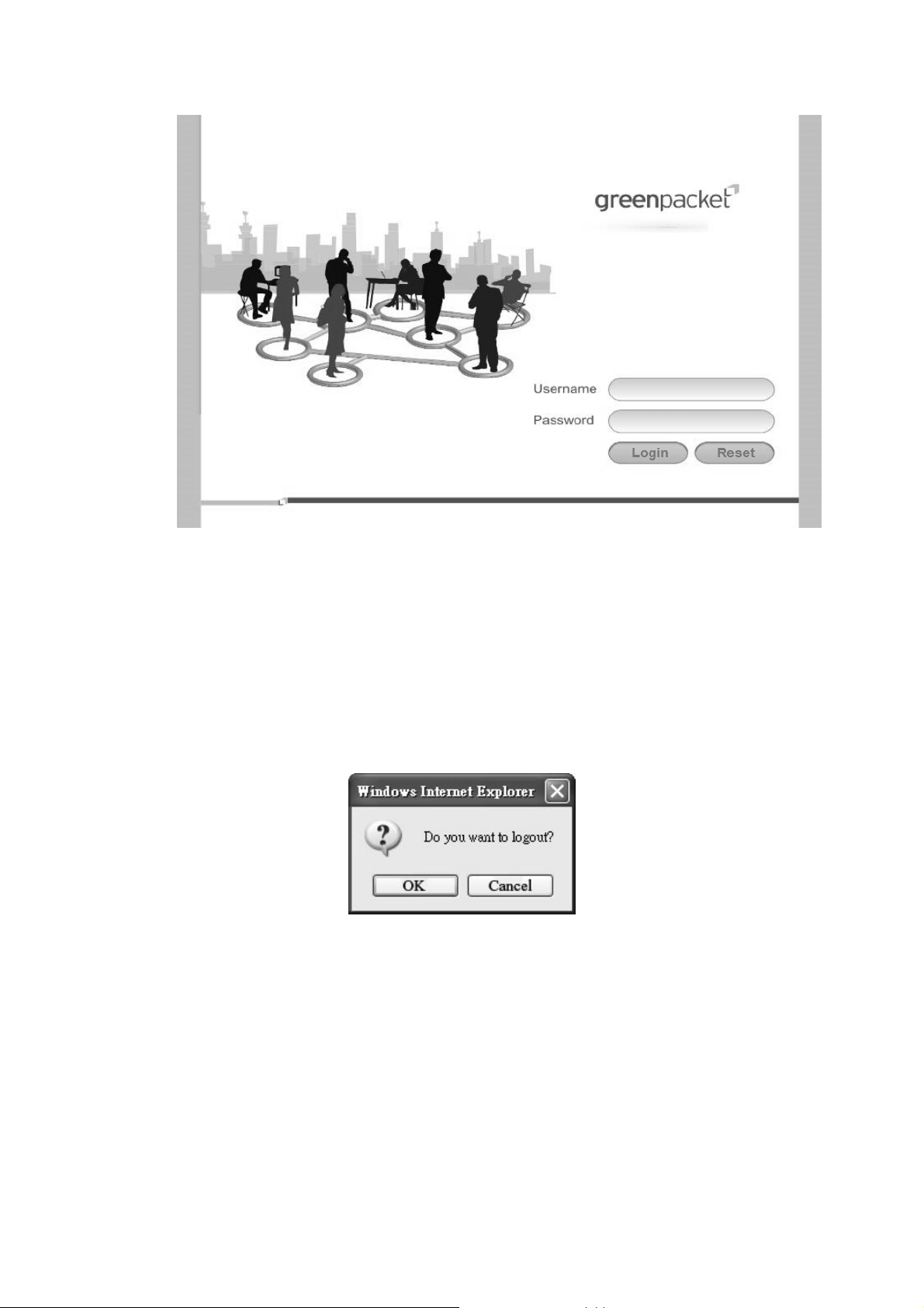
Figure 1 Login page
1.2. Logout
The “Log out” wind ow allows users to disconnect from the d evice and exit the W eb-based
Configuration Manager.
Figure 2 Logout
12
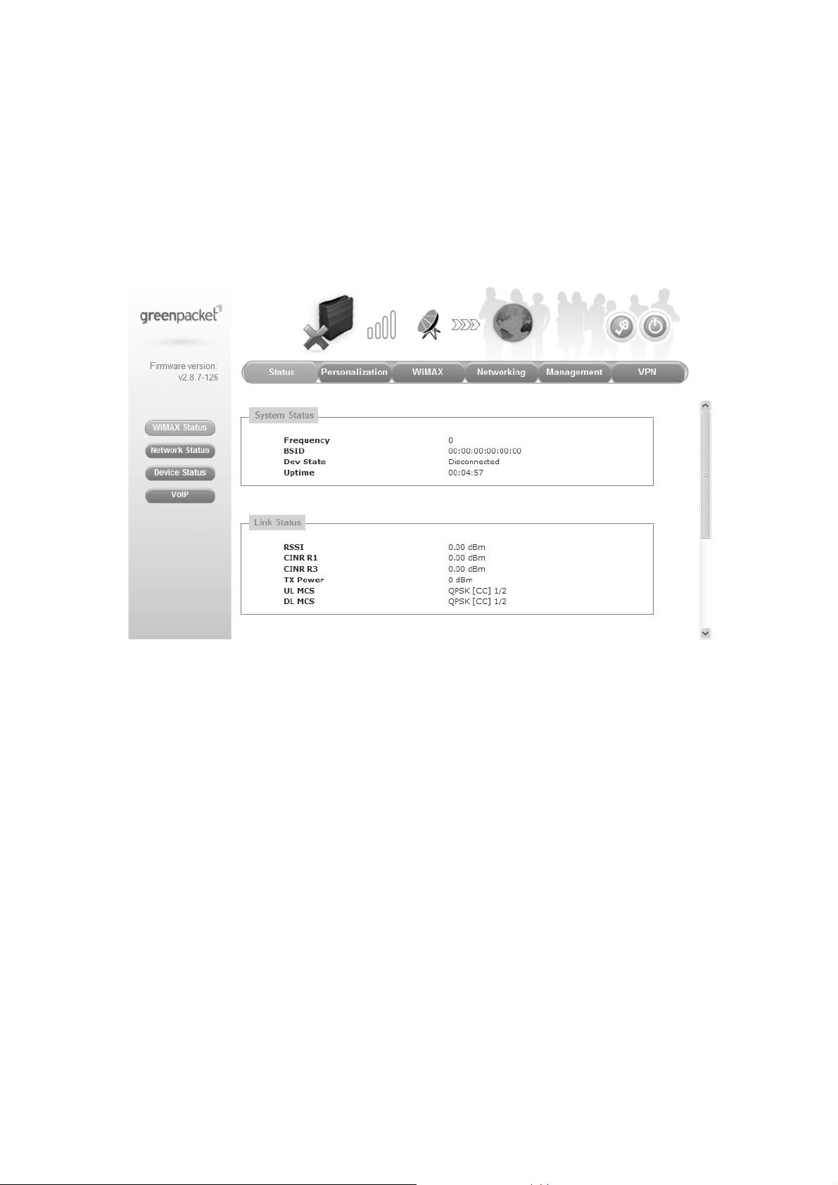
1.3. Status
After user has established a connection, user will see the “Status” window. This window shows
all the st atus and system information. It gives user an initial overview of the current st atus of
the device.
Figure 3 Status window
1.4. Device Status
The “Device status” wi ndow displ ays firmwa re versi on informatio n of the WiMAX Out door
CPE.
13

Figure 4 Device status
14
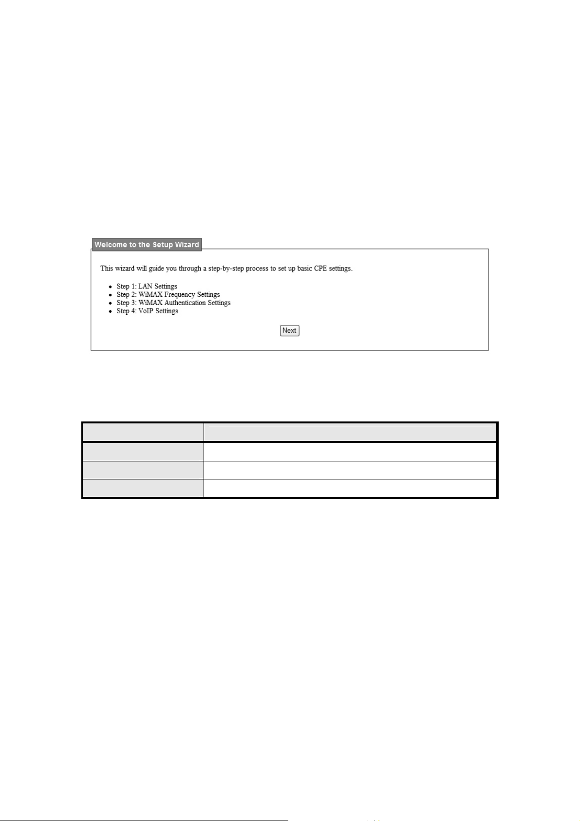
1.5. Setup Wizard
The setup wizard will allow user to quickly configure the basic networking settings on the CPE.
Click the “Setup Wizard” menu item to enter the wizard. The first page will display all the steps
necessary to complete the wizard settings as shown in Figure 5. Later, click the “Next” button
to continue the next steps. The definition of each button shown on web page is defined in the
Table 1.
Figure 5 Setup Wizard
Name
Next Continue to the next step
Back Return to the previous step
Save Commit the changes made and save to WiMAX outdoor CPE
Table 1 Button definition shown on Setup Wizard
Description
15
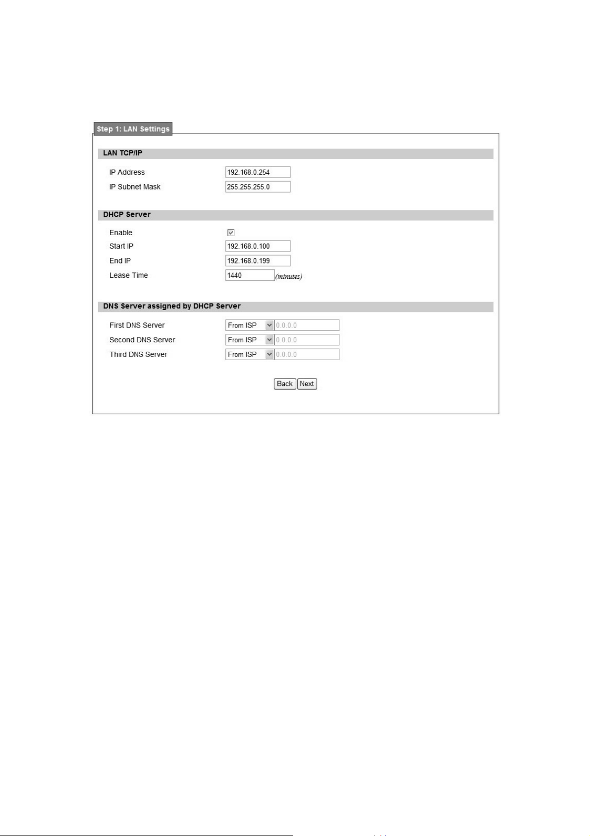
Step 1: LAN Settings. In this step user can configure both IP and DHCP configuration
parameters as shown in Figure 6.
Figure 6 Wizard LAN Settings in Setup Wizard
16
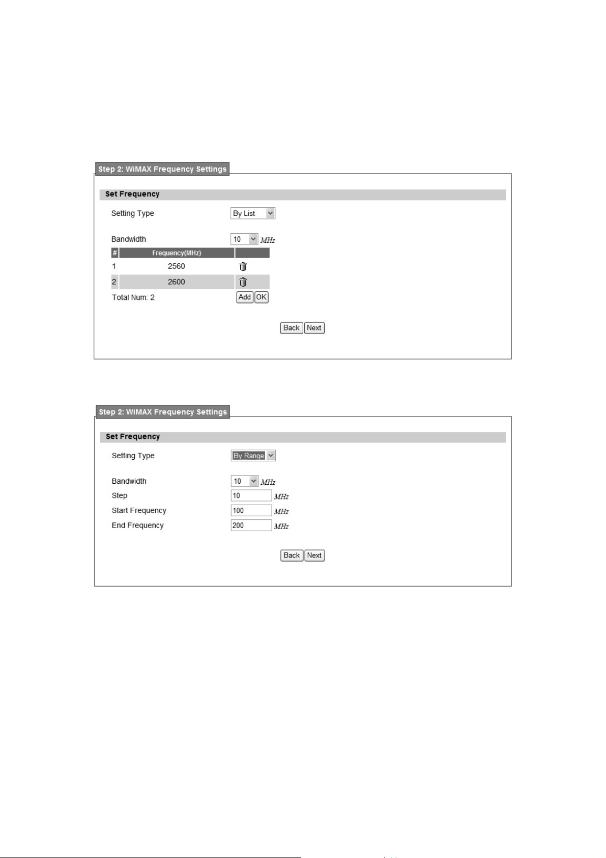
Step2: WiMAX Frequency Settings. This step will qui ckly configure the WiMAX
frequencies. There are two types of configuring the frequencies. User can configure it through
simply entering a frequency in the frequen cy list as shown in Figure 7 or by gi ving a starting
and ending frequency value and a step size to traverse the range as shown in Figure 8.
Figure 7 WiMAX Frequency Settings By List in Setup Wizard
Figure 8 WiMAX Frequency Settings By Range in Setup Wizard
17
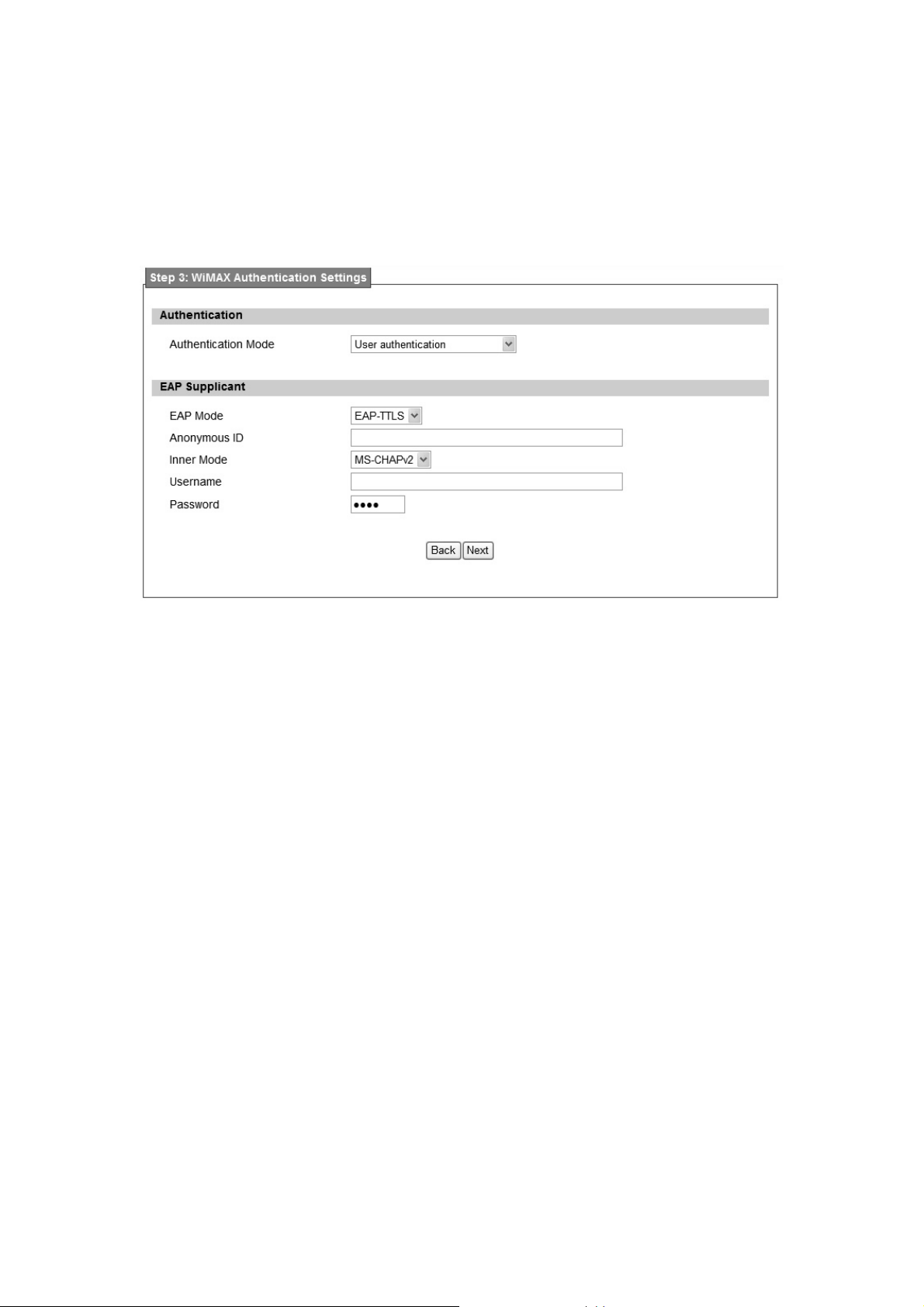
Step 3: WiMAX Authen tication Settings. Thi s will config ure WiMAX Auth entication
settings. The re are 4 possible options for “Authentication Mode” as No authentication, User
authentication, Device au thentication, and Us er an d device aut hentication. Dep ending o n
which mode user selects, and it will appear different EAP settings for configuration. Except “No
authentication” is selected, user needs to define the EAP supplicant as shown in Figure 9.
Figure 9 WiMAX Authentication Settings in Setup Wizard
Detailed definition of each item in EAP supplicant is listed below.
EAP Mode: WiMAX outdoor CPE suppor ts EAP-TLS, EAP-TTL S, EAP-SIM, and
EAP-AKA.
Anonymous ID: User needs to fill the Outer ID at this field.
Inner Mode: WiMAX out door CPE supports MS-CHAPv2, MS-CHAP, CHAP, MD5,
and PAP.
Username: User needs to fill username at this field.
Password: User needs to fill password at this field.
Once the u ser compl etes all the ste ps, user needs to click the “Save” b utton to save th e
settings, or click “Ba ck” button to return to previous step as shown in Figure 10. It will reload
some services and return to the “Home” window after saving all settings.
18

Figure 10 Wizard Save
19

2. Network
Refer to Figure 101, for proper network connection.
Figure 11 Network Topology
2.1. LAN
2.1.1. IP
From the “Network>LAN>IP” window, user can update the LAN information as shown in Figure
12. The definition for each field is shown on Table 2.
Figure 12 Network>LAN>IP
20

Name Description
IP Address IP address of the WiMAX outdoor CPE
IP Subnet Mask Subnet Mask of the WiMAX outdoor CPE
Save
Cancel Reset the fields to the last saved values
Commits the chan ges m ade, and set the LAN IP information ,
some services will be reloaded.
Table 2 Field definition for Network>LAN>IP
2.1.2. DHCP
Use the “Net work>LAN>DHCP” t ab to configure the DHCP serve r inform ation. The defa ult
DHCP Server setup is ena bled, and user co uld disable this functi on from setu p as sho wn in
Figure 13. When u ser disables the DHCP server, it requires to set a static IP address on host
PC for CPE to configure. Please be noted that without the static IP address set properly on the
host PC, user can not open the CPE web page for configuration.
When DHCP se rver i s e nabled, user need s to define the IP pool range f or dyn amically
assigning the IP address. The advant age of using DHCP server is that the addre sses which
are no longer in use will be returned to the IP address pool so that the server can reallocate
them to other machines in the network.
There are three DNS servers the user can configure to assign an IP address. Static DHCP will
assign an IP address on the LAN to a specific device based on its MAC address. The definition
for each field is shown on Table 3.
21
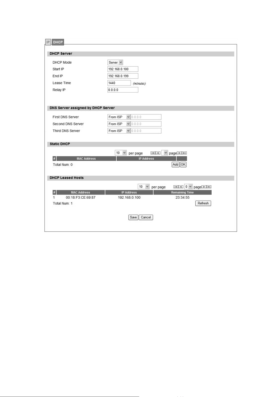
Figure 13
Network>LAN>DHCP
22

Name Description
If the enable box is ch ecked for D HCP server, the DHCP server
Enable
Start IP Starting IP address range
End IP Ending IP address range
Lease Time
First DNS Server
Second DNS Server
Third DNS Server
will assig n IP addre ss to it s clie nt with the sp ecified IP addre ss
range.
The lea se time is a cont rolled time p eriod, allo wing the DHCP
server to reclaim (and then reallocate) IP addresses that are not
renewed (dynamic re -use of IP ad dresses). Le ase tim e i s
measured in minutes in the Configuration Manager.
User can sp ecify three DNS serve r and select how the DNS
Server is assigned. There are three options for assigning the DNS
server.
From ISP
User Defined
Non e
If user sel ects “None”, then the DH CP server will no t give clients
the DNS se rver inform ation. If a ll the three DNS servers setting
are set to “Non e”, then the DHCP server will u se the LAN IP
address as the DNS server information for the clients. If the user
chooses “User Defined” and leaves the IP address as “0.0.0.0” it
will change the field to “None”.
Add
OK Click the “OK” button to exit out of edit mode.
Save
Cancel Reset fields to the last saved values.
Table 3 Field definition for Network>LAN>DHCP
Click on the “Add” button to enter a static leased IP address. Enter
the MAC address of the Ethernet device and enter the IP address.
Commit the changes ma de an d save to WiMAX outdoor CPE,
some services will be reloaded.
2.2. WAN
The wide area netwo rk i s anothe r network that user can conn ect to the internet with the
23
WiMAX outdoor CPE.
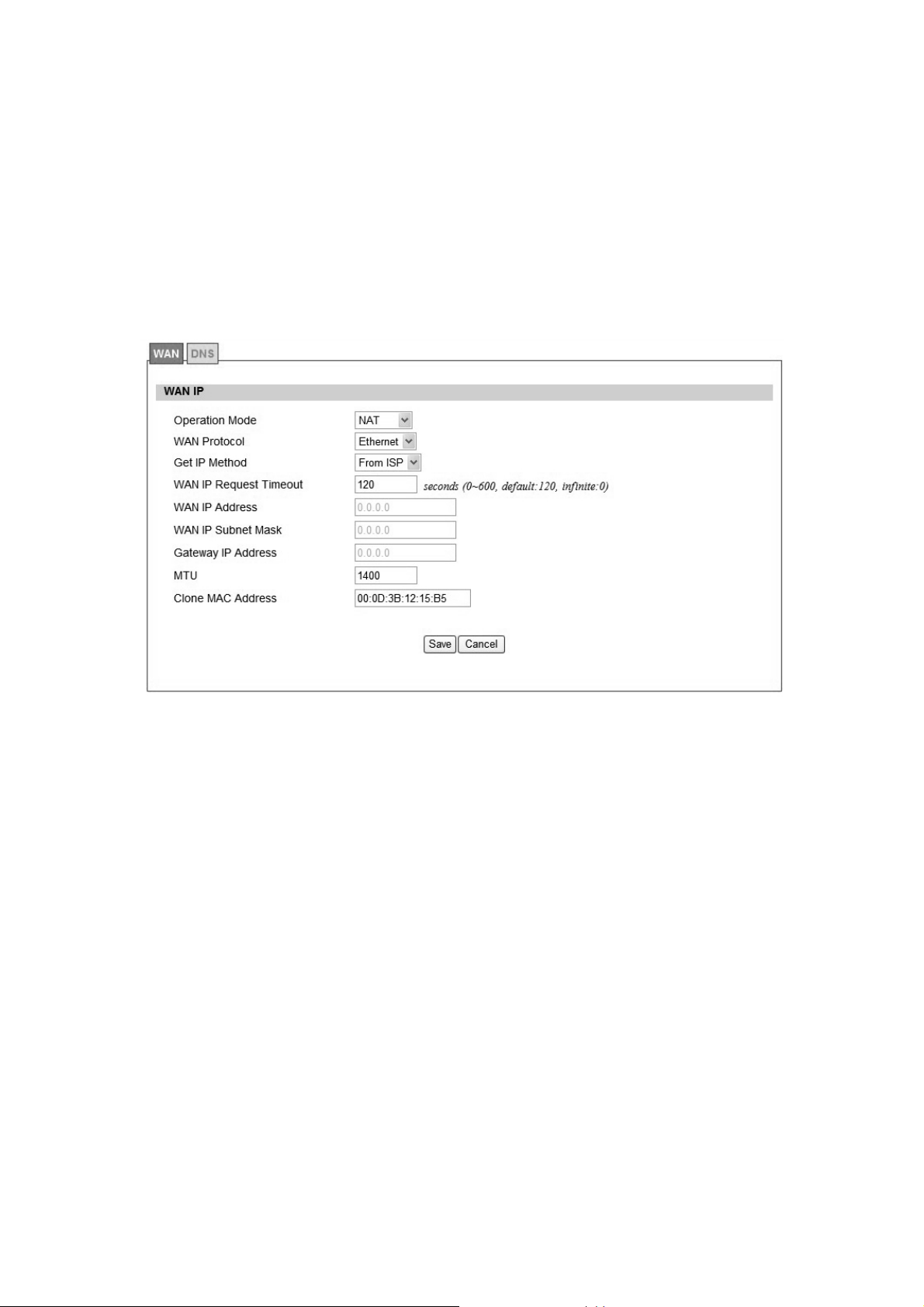
2.2.1. WAN
In Figure 14, it demonstrates ho w to configure WAN IP on CPE web p age. The definition for
each field is shown on Table 4.
Figure 14 Network>WAN>WAN
24

Name Description
Select the WAN operation mode
Operation Mode
WAN Protocol
Get IP Method
WAN IP Request Timeout
WAN IP Address
Bridge
Routin g
NA T
Select the WAN encapsulation protocol
Ethernet
PPPoE
Enter the IP method
From ISP
Us er
The time the DHCP client waits to re ceive the IP address from
the BS. If it doesn’t get the IP , it will timeout and the CPE will
disconnect the WiMAX conne ction. T he default value is 12 0
seconds. If u ser ente rs 0, it will wait to receive the IP addre ss
infinitely until it’s stopped by the user.
If user chooses “User” for IP Method, user should enter the WAN
IP address
WIN IP Subnet Mask
If user chooses “User” for IP Method, user should enter the WAN
IP subnet mask.
If us er chooses “User” for IP Method, use r shou ld enter IP
Gateway IP Address
gateway address
MTU Enter the MTU
Clone MAC Address Enter the clone MAC address to be used by WAN
PPPoE Setting
The user name to c onnect PPPoE s erver via the selec ted Auth
User Name
Protocol
Password The password of the corresponding username
Retype Password Type the “Password” again
The a uthentication protocol of t he p eer re quired. S elect which
Authentication protocol to use.
P AP
Auth Protocol
CHAP
MSCHAPv1
MSCHAPv2
25
Encryption Scheme
No
Encryption
Idle Timeout Disconnect if the link is idle for the assigned seconds
AC Name The name of the access concentrator to connection to
Save
Cancel Reset field to the last saved values
Table 4 Field definition for Network>WAN>WAN
MPPE 40 bits: 40-bit encryption with MPPE
MPPE 128 bits: 128-bit encryption with MPPE
Auto: automatically selected
Commit the changes ma de and save to WiMAX ou tdoor CPE,
after clicking the Save button user will get a message aski ng if
user want s t o reb oot the CPE. Reb oot is ne cessary for the
device to switch to a different profile.
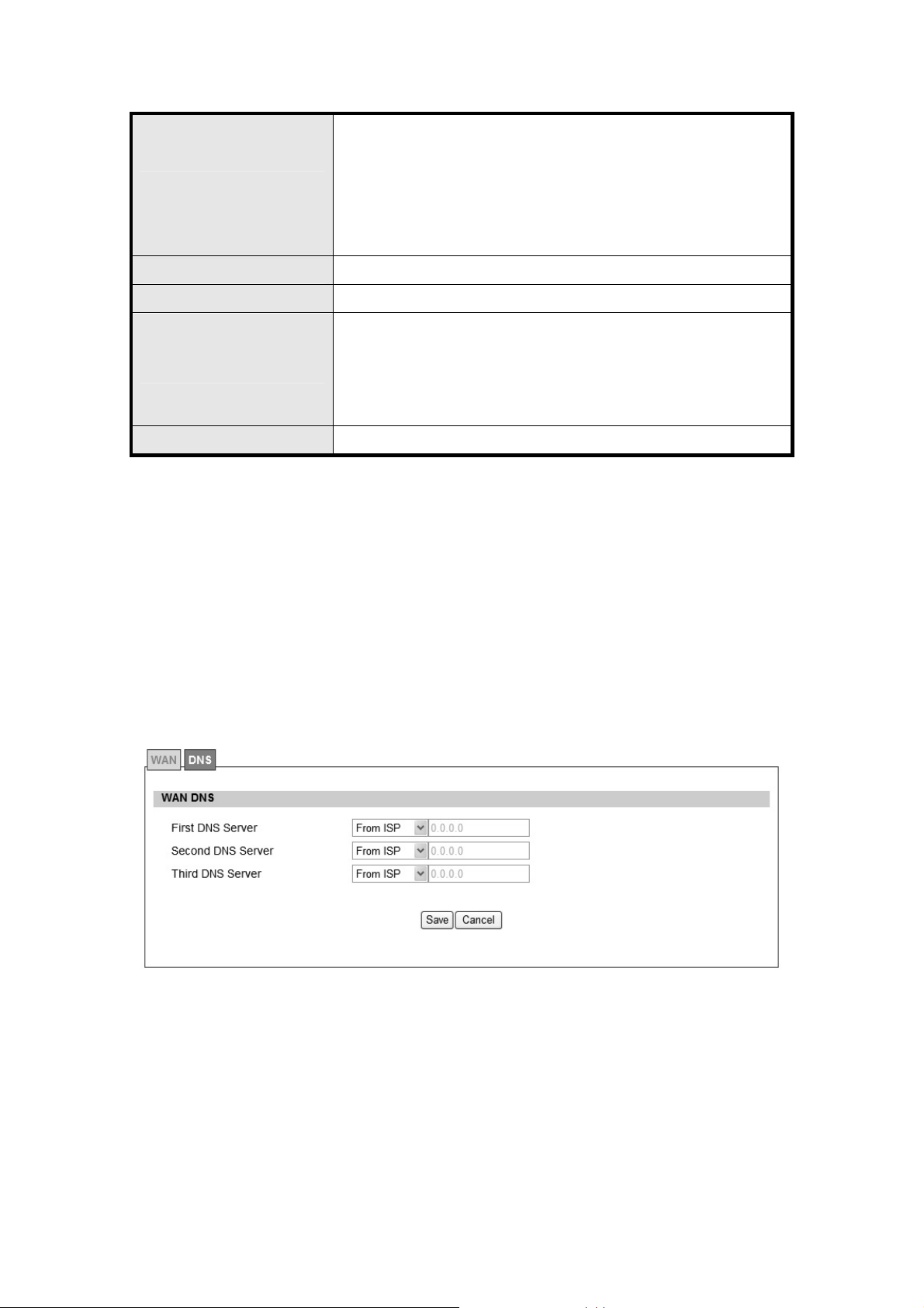
2.2.2. DNS
In Figure 15, it demonstrates how to configure WAN DNS on CPE web page. The definition for
each field is shown on Table 5.
Figure 15 Network>WAN>DNS
26

Name Description
Enter the WAN DNS information.
User Defined
First DNS Server
Second DNS Server Same as First DNS Server
Third DNS Server Same as First DNS Server
Save Commit the changes made and save to WiMAX outdoor CPE
Cancel Reset fields to the last saved values
From ISP
If user sele cts “User Define”, u ser n eeds to ente r a valid IP
address for the DNS server.
Table 5 Field definition for Network>WAN>DNS
27
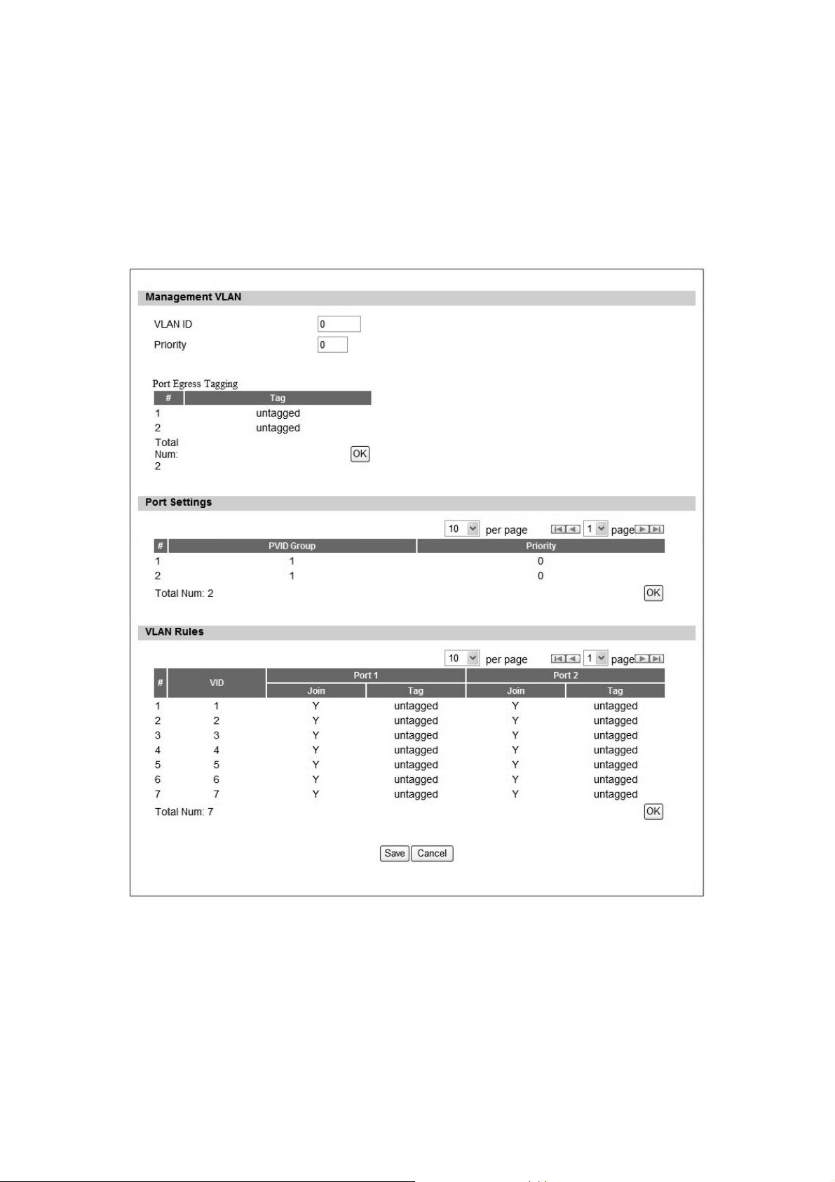
2.3. VLAN
In Figure 16, it demonstrates how to configure VLAN setting on CPE web page. The definition
for each field is shown on Table 6.
Figure 16 Network>VLAN
28

Name Description
Management VLAN
VLAN ID Setting the management VLAN ID
Priority Setting the management Priority
Port Settings
PVID Group Select the VLAN group as the PVID
Priority Setting the port priority
VLAN Rule
VID Setting the VID of this group
Join Add this port into this group
Tag
Save Commit the changes made and save to the CPE device
Cancel Reset fields to the last saved values
Mark the out-going packets of this port i n this VLAN as tagged or
untagged
Table 6 Field definition for Network>VLAN
2.4. DDNS
DDNS st ands for Dy namic Dom ain N ame Serv ices. It provides a function to conve rt the
domain name to the uni que IP address. With DDNS, users is able to find and connect to CPE
no matter wh at IP address CPE is curre ntly using, that is, DDNS can map CP E's dynamic IP
address to a static hostname. The best profit of this function allows user to access CPE from
everywhere.
In Figure 17, it demonst rates how to confi gure DDNS on CPE web page. The definition for
each field is shown on Table 7.
29
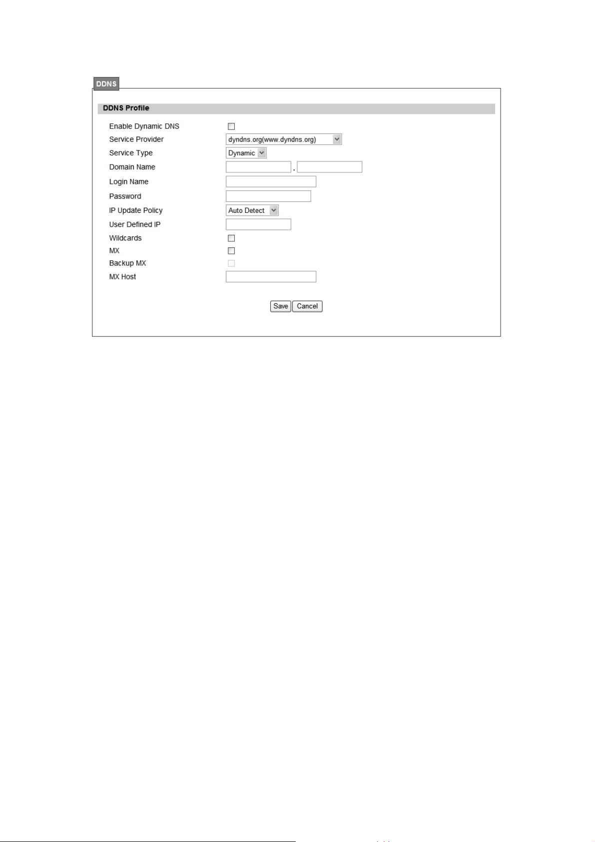
Figure 17 Network>DDNS
30
 Loading...