

Page 1

TiNet S8600-04 GPON OLT
User Manual
Hardware Configuration Manual
1. Product Description
2. Specifications and Characteristics
3. Preparation Before Installation
4. Installation
5. Startup and Configuration
6. Software Upgrade
7. Troubleshooting
8. Optional Interface Modules
9. Appendix RJ-45 Connector
Page 2

Shenzhen New Greennet Technologies Co., Ltd. Contents
I
Contents
Chapter 1 Product Description.......................................................................................................... 1-1
1.1 Basic Information.......................................................................................................................1-1
1.2 Typical Applications...................................................................................................................1-1
Chapter 2 Specifications and Characteristics...............................................................................2-1
2.1 Appearance................................................................................................................................ 2-1
2.2 Front Panel.................................................................................................................................2-1
2.2.1 Front Panel......................................................................................................................2-1
2.2.2 Attributes of GPON OLT SFP Ports............................................................................2-4
2.3 Rear Panel of TiNet S8600-04 GPON OLT.......................................................................... 2-6
2.3.1 Rear Panel...................................................................................................................... 2-6
2.3.2 Optional Power Modules for Power Module Slots....................................................2-6
2.4 System Characteristics.............................................................................................................2-7
Chapter 3 Preparation Before Installation...................................................................................... 3-1
3.1 Safety Precautions....................................................................................................................3-1
3.2 Installation Site Inspection.......................................................................................................3-1
3.2.1 Temperature/Humidity...................................................................................................3-2
3.2.2 Cleanliness......................................................................................................................3-2
3.2.3 Immunity to Interference...............................................................................................3-3
3.3 Installation Tools and Devices.................................................................................................3-4
Chapter 4 Installation............................................................................................................................4-1
4.1 Mechanical Installation.............................................................................................................4-1
4.1.1 Installing the Device in a Cabinet................................................................................4-1
4.1.2 Installing the Device onto a Workbench.................................................................... 4-2
4.2 Connection of Power Cables and Ground Cables...............................................................4-3
Page 3

Shenzhen New Greennet Technologies Co., Ltd. Contents
II
4.2.1 AC Power Supply and Installation...............................................................................4-3
4.2.2 DC Power Supply Installation...................................................................................... 4-3
4.2.3 Installing the Ground Cable......................................................................................... 4-4
4.3 Connecting the Console Cable...............................................................................................4-4
4.3.1 Installing the Console Cable........................................................................................ 4-4
4.3.2 Connecting the Console Cable....................................................................................4-5
4.4 Check after Installation.............................................................................................................4-5
Chapter 5 Start and Configuration....................................................................................................5-1
5.1 Local Terminal Configuration...................................................................................................5-1
5.1.1 Creating a Configuration Environment.......................................................................5-1
5.1.2 Connecting the Console Cable....................................................................................5-1
5.1.3 Setting Terminal Parameters........................................................................................5-1
5.2 Powering On the OLT............................................................................................................... 5-7
5.2.1 Checking the OLT Before Power-on...........................................................................5-7
5.2.2 Powering On the Device...............................................................................................5-8
Chapter 6 Software Upgrade.............................................................................................................. 6-1
Chapter 7 Troubleshooting................................................................................................................. 7-1
7.1 Power Supply System Failure.................................................................................................7-1
7.2 Configuration System Failure..................................................................................................7-1
7.2.1 No Terminal Display.......................................................................................................7-1
7.2.2 Garbled Characters....................................................................................................... 7-2
Chapter 8 Appendix RJ-45 Connector............................................................................................. 8-3
8.1 RJ-45 Connector....................................................................................................................... 8-3
8.2 Cable making............................................................................................................................. 8-5
Page 4

Shenzhen New Greennet Technologies Co., Ltd.
1
Chapter 1 Product Description
1.1 Basic Information
TiNet S8600-04 is New Greennet's self-developed frame-type GPON OLT,
boasting high performance, high port density, ease of installation, good
expandability, and low cost. The OLT provides one control board slot and five
service board slots and allows you to mix Gigabit uplink subboards and
10-Gigabit subboards. TiNet S8600-04 enables access to a variety of
IP/Ethernet services in point-to-multipoint networks, including emerging IP
broadband services such as IPTV/VOD, VoIP, and videophone and enterprise
services such as VPN and video conferencing. Besides providing Gigabit fiber
optic transmission capacity, the OLT also reduces service deployment and
management costs for its cost-effectiveness and good expandability.
1.2 Typical Applications
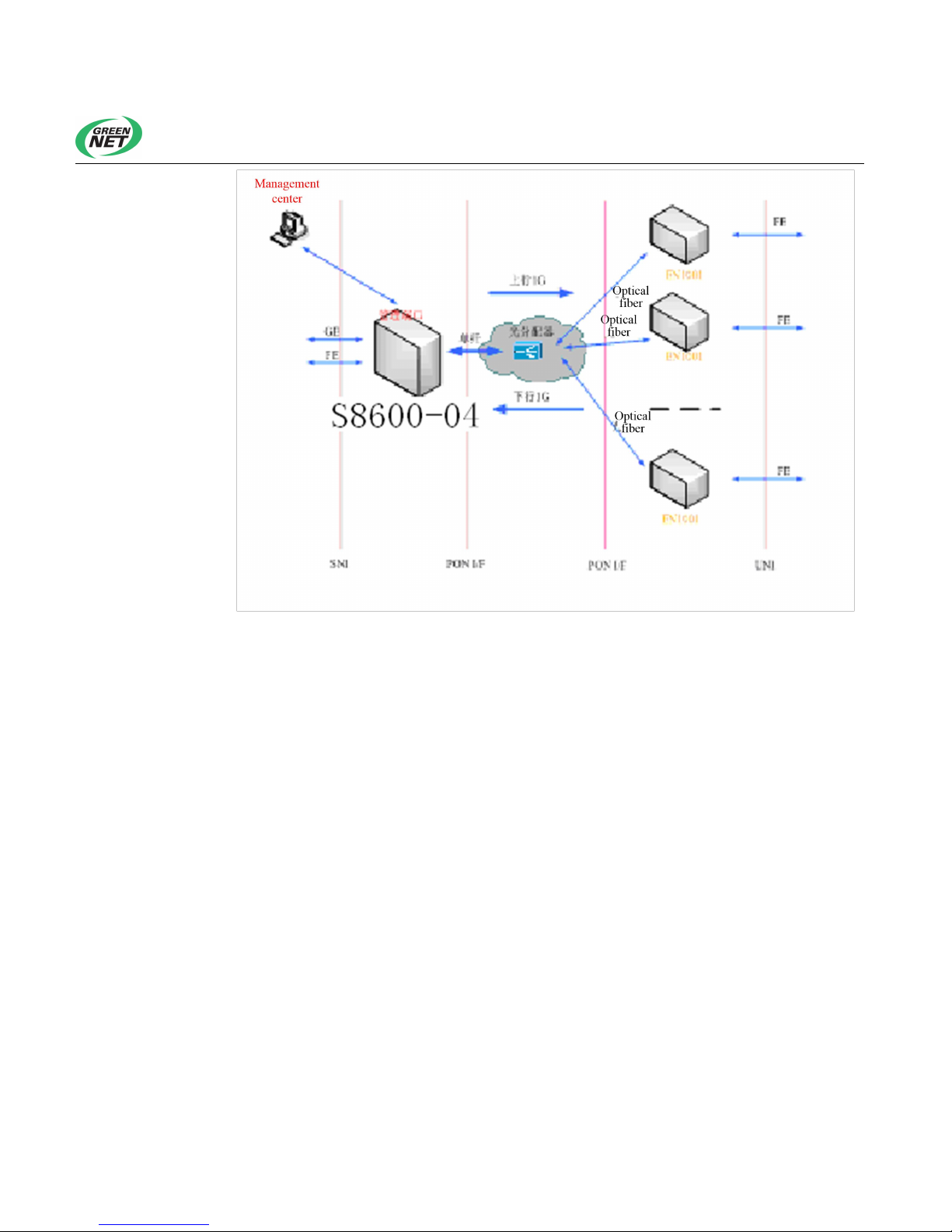
TiNet S8600-04 GPON OLT employs the modular design, and can be
deployed on an enterprise network or used for broadband access.
Page 5
Shenzhen New Greennet Technologies Co., Ltd.
2
Page 6
Shenzhen New Greennet Technologies Co., Ltd.
1
Chapter 2 Specifications and Characteristics
2.1 Appearance
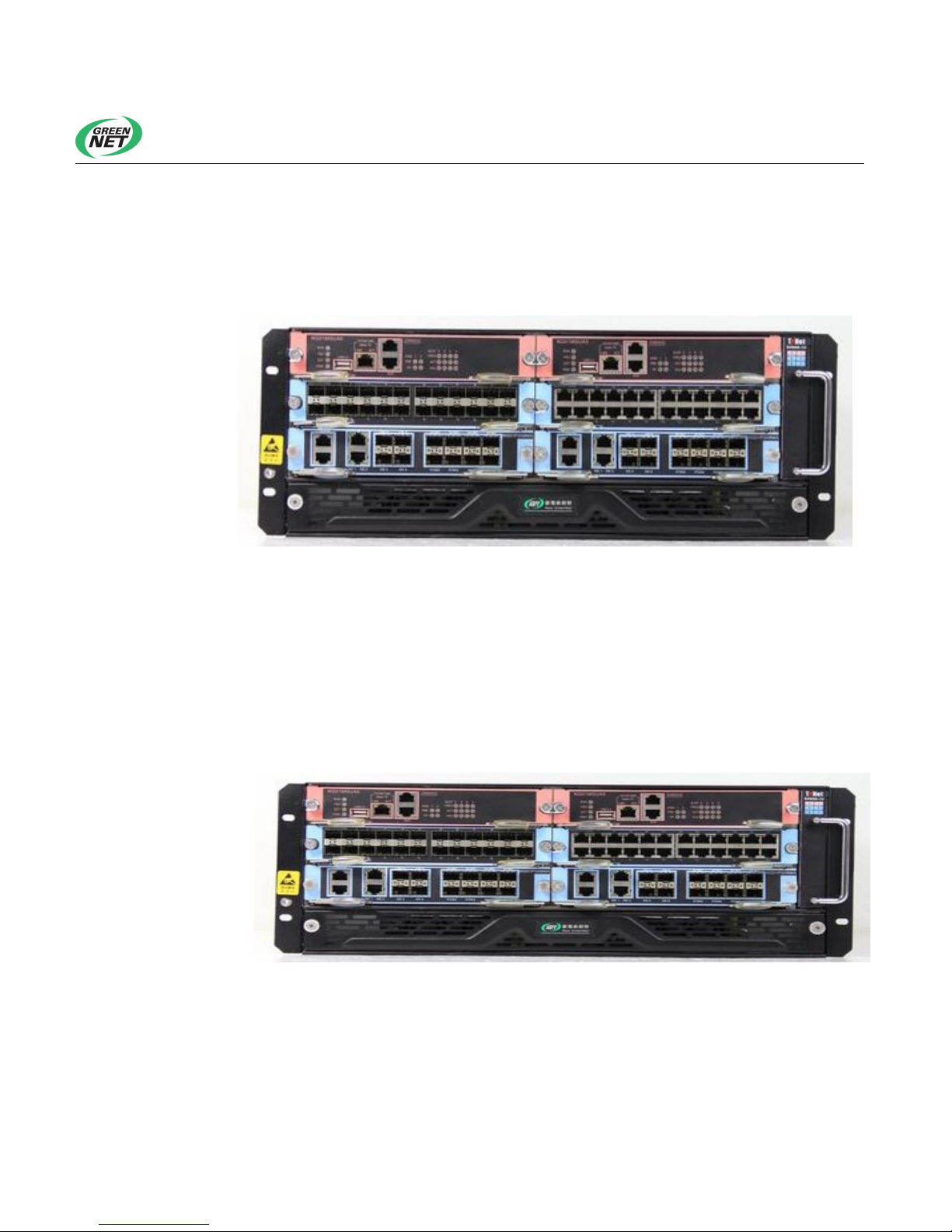
Figure 2-1 TiNet S8600-04 GPON OLT appearance
2.2 Front Panel
2.2.1 Front Panel
Figure 2-2 shows the layout of the front panel of the TiNet S8600-04 GPON
OLT, including two control card slots and four line card slots:
Figure 2-2 Front panel of the TiNet S8600-04 OLT
Slot 0 – for active control card NG01MSUA0
Slot 1 - houses standby control card NG01MSUA0
Page 7
Shenzhen New Greennet Technologies Co., Ltd.
2
Slots 2-5 - house four NG01PG08MAs (OLT service board) or
NG01GT24MAs with Gigabit uplink electrical ports
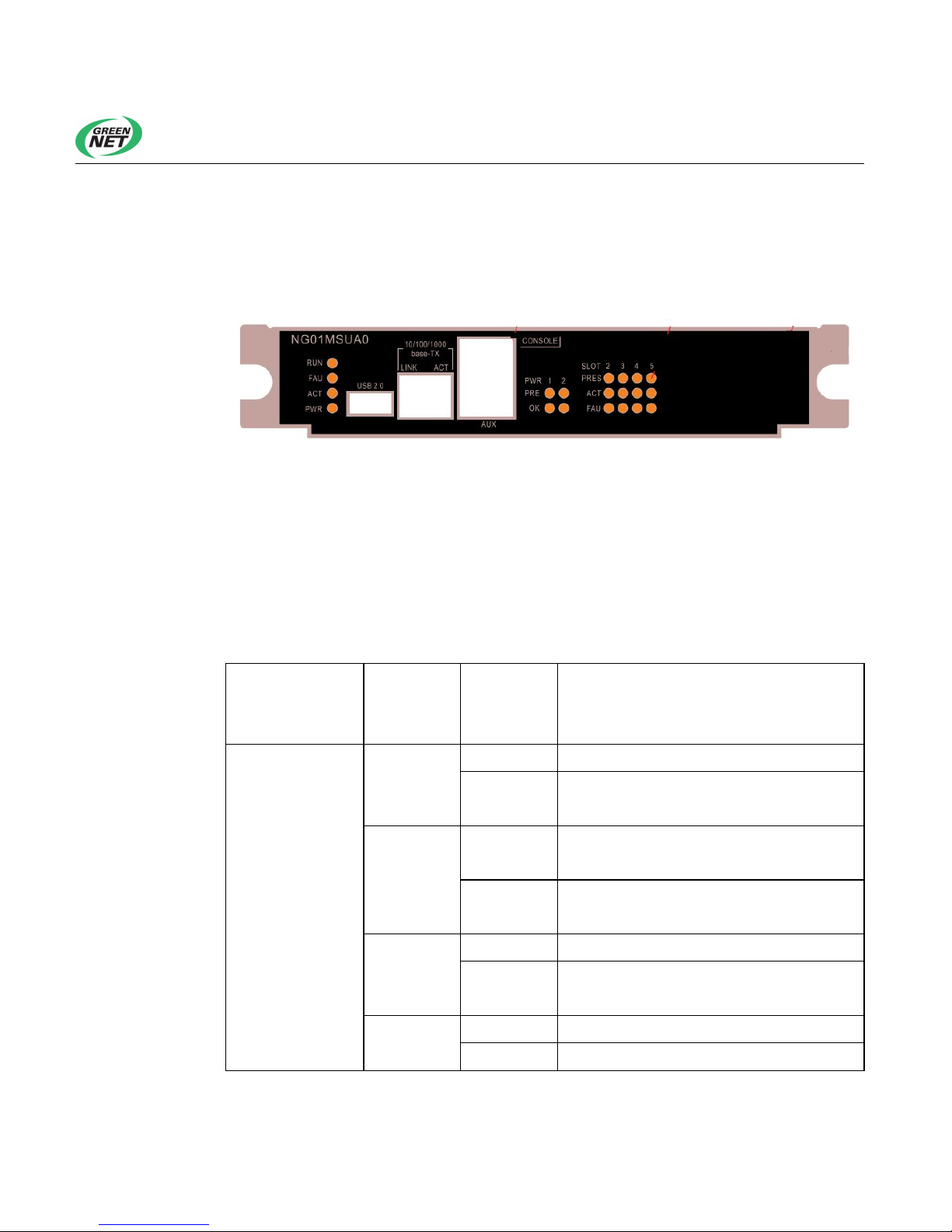
The panel of a control board of the TiNet S8600-04 GPON OLT is as shown
below:
The panel provides several LED indicators, a USB backup port, an RS232
serial console port (marked CONSOLE), a port for management (marked
AUX), and a port for remote login.
Front panel LED indicators are explained as given in Table 2-1:
Table 2-1 Meanings of LED indicators on the front panel of a control board of TiNet
S8600-04 GPON OLT
Indicator
Sign on
the Front
Panel
Status Meaning
System status
indicators
RUN
Flashing The OLT is running properly.
Always
ON or OFF
The OLT malfunctions.
FAU
Always
ON
Always
OFF
ACT
Always On The current control board is running.
Always
OFF
Backup main control panel status
PWR
On The power supply is normal.
Off A power supply failure occurs.
Page 8
Shenzhen New Greennet Technologies Co., Ltd.
3
Indicator
Sign on
the Front
Panel
Status Meaning
PWR in-position PRES
Always on The power module can be detected.
Always
OFF
The power module slot is vacant or the
power module is faulty.
OK
Always on The power module is operating normally.
Always
OFF
The power module slot is vacant or the
power module is faulty.
SLOT status
indicators
PRES
Always on The slot has a line board.
Always
OFF
The slot does not have a line board.
ACT
Always on The slot is operating normally.
Always
OFF
The slot is faulty or does not have a
board.
FAU
Always on The slot is faulty.
Always
OFF
The slot is operating normally.
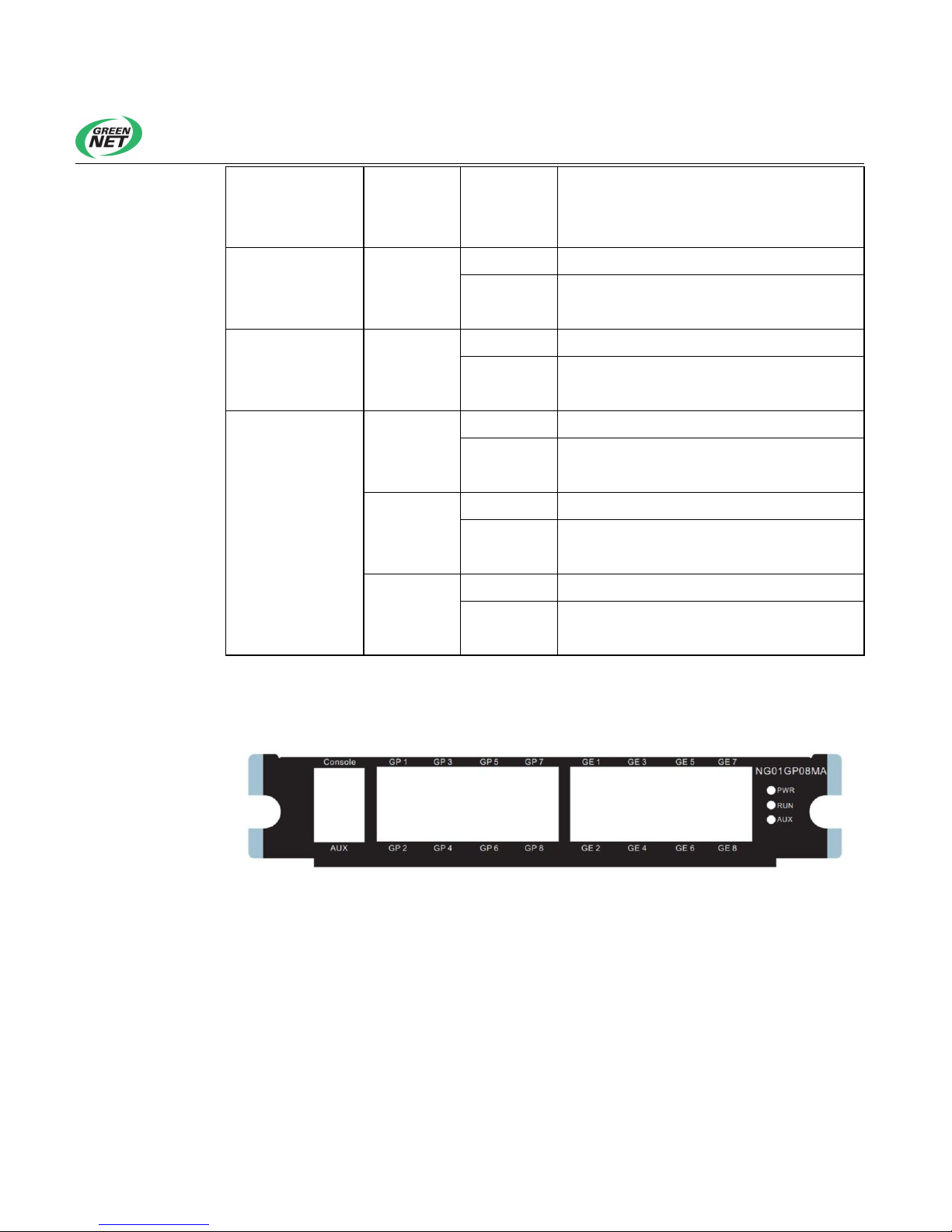
The front panel layout of a line board of TiNet S8600-04 GPON OLT is as
shown below:
The panel provides eight 1000 Base-x SFP uplink ports GE1 ~ GE8, eight
GPON OLT SFP ports GP1 ~ GP8, one RS232 Console port, one port for
commissioning AUX. The LED indicators are explained as given in Table 2-1:
Page 9

Shenzhen New Greennet Technologies Co., Ltd.
4
Table 2-2 Indicators on the front panel of a line board of TiNet S8600-04 GPON OLT
Indicator
Sign on the
Front
Panel
Status Meaning
Power
indicator
PWR
On
The board is operating under normal voltage.
Off
The board is operating under abnormal
voltage.
Single panel
running
indicator
RUN
Blinking The CPU of the board is normal.
Off The CPU of the board is abnormal.
Indicator for
the port for
commissioning
AUX
Off
The AUX port is connected improperly or
unconnected.
On The AUX port is connected properly.
Flashing
The AUX port is connected properly and is
transmitting data.
GE status
indicator
GE
Off
The GE port is connected improperly or
unconnected.
On The GE port is connected properly.
Flashing
The AUX port is connected properly and is
transmitting data.
GPON status
indicator
GP
Off No ONU is registered with the PON port.
On
There is at least one ONU registered with the
PON port.
Flashing
The PON port has registered ONUs and is
transmitting data.
2.2.2 Attributes of GPON OLT SFP Ports
The front panel of TiNet S8600-04 OLT provides up to 32 GPON OLT SFP
ports and 24 GE Gigabit Ethernet ports. SFP modules are hot swappable and
can be configured flexibly, which improves networking flexibility. Users may
select the desired SFP modules according to Table 2-4.
Page 10

Shenzhen New Greennet Technologies Co., Ltd.
5
Table 2-3 Optional modules for GPON OLT SFP interface
SFP Module
Center
Wavelength
Connector
of the
Optical
Cable
Fiber
Specifications
Maximum
Transmission
Distance of
Optical Fibers
SFP-GPON-LH10
1310 nm in
receiving, 1550
nm in sending
LC
Single-mode
fiber
10km
SFP-GPON-LH20
1310 nm in
receiving, 1550
nm in sending
Single-mode
fiber
20km
Table 2-4 Optional modules for GE Gigabit Ethernet SFP interface
SFP Module
Center
Wavelength
Connector
of the
Optical
Cable
Fiber
Specifications
Maximum
Transmission
Distance of
Optical Fibers
SFP-GE-SX-MM850 850 nm
LC
Multimode
fiber
550m
SFP-GE-SM1310-LH10
1310 nm
Single-mode
fiber
10km
SFP-GE-SM1310-LH20 20km
SFP-GE-SM1310-LH40 40km
SFP-GE-SM1550-LH40
1550 nm
40km
SFP-GE-SM1550-LH60 60km
Gigabit SFP modules may be updated from time to time. Consult the
marketing staff of New Greennet for latest module information.
Page 11
Shenzhen New Greennet Technologies Co., Ltd.
6
2.3 Rear Panel of TiNet S8600-04 GPON OLT
2.3.1 Rear Panel
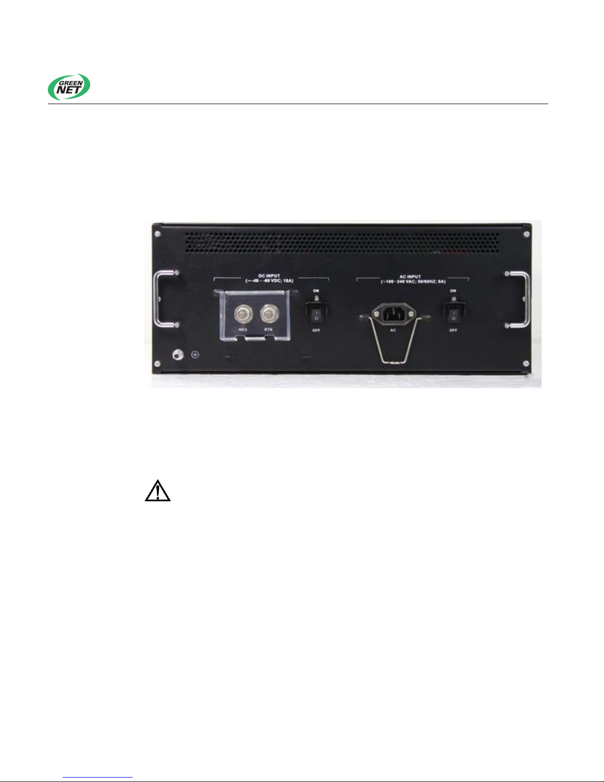
Figure 2-3 shows the rear panel of TiNet S8600-04 OLT, on which two power
module slots and one grounding post are available.
Figure 2-3 Rear panel of TiNet S8600-04 GPON OLT
1 - 2 power input options;
2 – Grounding post;
TiNet S8600-04 GPON OLT supports both AC and DC power
supply.
2.3.2 Optional Power Modules for Power Module Slots
The rear panel of TiNet S8600-04 GPON OLT has two power options. The
power input can be either of the following:
POWER-AC750: 750W AC power supply module (176~264V/50~60Hz)
POWER-DC750: 750W DC power module (-36V~-72V DC input)
Page 12

Shenzhen New Greennet Technologies Co., Ltd.
7
2.4 System Characteristics
Table 2-8 System characteristics of TiNet S8600-04 GPON OLT
Item TiNet S8600-04 GPON OLT
Processor CAVIUM
BOOTROM 512 KB
SDRAM 2 GB
FLASH 8 MB
Dimensions (W ×
H × D)
442 mm × 175 mm × 420 mm
Weight <40 kg
Input Voltage
AC: 176V~264V 47/63Hz
DC: -36V ~ -72V
Maximum Power < 750W
Port
32 GPON OLT SFP ports
24 GE SFP ports
Switching mode Store-and-forward
Switching
Capacity
960Gbps
Standards
Compliant
IEEE 802.3ah GPON
IEEE802.3 (10Base-T)
IEEE802.3u (100Base-TX)
IEEE802.3z (1000BASE-X)
IEEE802.3ab (1000Base-T)
IEEE802.1Q (VLAN)
IEEEE802.1d (STP)
IEEEE802.1W (RSTP)
IEEEE802.1S (MSTP)
IEEE802.1p (COS)
IEEE802.1x (Port Control)
IEEE802.3x (Flow Control)
IEEE802.3ad (LACP)
Each OLT interface supports up to 64 ONUs;
Page 13

Shenzhen New Greennet Technologies Co., Ltd.
8
Item TiNet S8600-04 GPON OLT
The transmission distance of each OLT is up to 20Km
L2 functions
VLAN, QinQ, link aggregation, Broadcast storm control
Supports up to 4096 VLANs;
Multicast
L3 multicast: IGMPv1/v2/v3, PIM-DM, PIM-SM, support for 1K L3
multicast routing tables
L2 Multicast: IGMPv2 in RFC 2236, IGMPv3 in RFC 3376, IGMP
Filter, IGMP Fast leave, controllable multicast, inter-VLAN
multicast replication, support for 1K L2 multicast groups
ACL/QOS
Supports standard and extended ACLs. A maximum of 2K to 6K
ACL rules can be effective simultaneously.
Supports Time-Range-based ACL policy
Provides flow classification and flow definition based on such IP
packet header information as source/destination MAC address,
VLAN, 802.1p, ToS, DiffServ, source/destination IP (IPv4/IPv6)
address, TCP/UDP port number, and protocol type. The system
can identify a maximum of 2 K service flows concurrently.
Supports L2 ~ L7 and packet filtering 80 bytes further in IP packet
header.
Supports rate limitation by port or flow on packets receiving and
sending, and provides ordinary traffic policing and two-rate
three-color traffic policing on flows.
Supports priority marking by port or flow, and provides the priority
Remark function based on 802.1P and DSCP.
Supports Committed Access Rate (CAR), Traffic shaping and
traffic statistics.
Supports packet mirroring and packet redirection by port or flow
Supports advanced queue scheduling based on ports and flows.
Each port or flow can be configured with at most eight priority
queues, where queue scheduling algorithms such as SP, WRR,
and SP + WRR are applied.
Supports congestion avoidance mechanisms such as Tail-Drop
and WRED.
Page 14

Shenzhen New Greennet Technologies Co., Ltd.
9
Item TiNet S8600-04 GPON OLT
Security Features
Supports automatic display of the source MAC address of the host
that launches an attack, and automatic binding of IP and MAC
addresses, to prevent the ARP tables of normal users from being
tampered in ARP spoofing and gateway IP addresses from being
forged in ARP attacks.
The ARP traffic of each user can be limited and users with
abnormal ARP traffic may be automatically blacklisted.
Supports effective protection against various DOS attacks (such
as ARP attack, Synflood attack, Smurf attack, ICMP attack), ARP
monitoring, network worms and Blaster virus attack.
Supports port trust functions to detect illegitimate DHCP servers
and Radius servers.
Supports Unicast Reverse Path check (URPF), which can
effectively prevent IP address forgery and attacks.
Supports ACL-based flow filtering.
Supports IEEE 802.1x and AAA/Radius authentication.
Enables users to bind IP addresses, VLAN IDs, MAC addresses
and port numbers.
Supports DHCP Option82, and PPPoE + so that the physical
location information of users can be uploaded.
Supports plaintext authentication of OSPF, RIPv2 and BGPv4
packets and MD5 ciphertext authentication.
Supports IP Source Guard, guaranteeing DHCP service security.
Supports RFC3176 sFlow traffic analysis, achieving protocol or
address-based traffic monitoring and statistics.
Supports broadcast packet suppression.
Supports data logging and RFC 3164 BSD syslog Protocol.
Supports SSHv2 Secure Shell.
Supports login through Telnet of Security IP and password-based
login.
Supports hierarchical user protection to prevent intrusion from
unauthorized users, and grants different levels of users different
configuration rights.
Page 15

Shenzhen New Greennet Technologies Co., Ltd.
10
Item TiNet S8600-04 GPON OLT
Reliability
Supports HSRP and VRRP.
Supports BFD, FlexLink L2 link backup, LACP, enhanced STP
(healing time is less than 1s), GERP (healing time is less than 50
ms) and other link fault recovery and redundancy mechanisms.
Both host programs and configuration files are able to recover from
faults.
Boards are hot swappable.
Supports 1 +1 power supply hot backup.
Operating
Temperature
0oC~45oC
Operating
Humidity
10%~90%
Page 16

Shenzhen New Greennet Technologies Co., Ltd.
1
Chapter 3 Preparation Before Installation
3.1 Safety Precautions
To avoid device damage and bodily injury caused by improper use, observe
the following precautions:
Disconnect the device from a power source before cleaning it. Do not
clean it with a damp cloth or liquids.
Do not put the device near water or in damp places to prevent water and
moisture from entering the device chassis.
Do not place the device in a case or on a desk which is in unstable state
to prevent the device from dropping.
Maintain good ventilation and keep the air ducts of the device unblocked.
Be sure that the operating voltage of the device agrees with what is
marked on the device; otherwise, the device may operate improperly.
To avoid electric shock, do not open the shell without permission even if
the device is disconnected from a power supply.
3.2 Installation Site Inspection
The following conditions must be guaranteed regardless of where the TiNet
S8600-04 GPON device is installed (inside a cabinet or on a workbench):
A space is reserved at the air inlet and outlet of the device so that heat
dissipation of the device chassis can be expedited.
The cabinet or workbench is fitted out with a sound ventilation system.
The cabinet or workbench is secure enough to support the weight of the
device.
Page 17

Shenzhen New Greennet Technologies Co., Ltd.
2
The cabinet or workbench is correctly grounded.
To ensure normal operation of the device and prolong its service life, the
installation site should also meet the following requirements.
3.2.1 Temperature/Humidity
Constant temperature and humidity should be maintained inside the machine
room. If the machine room is kept humid inside in a long time, symptoms,
such as poor insulation and even electric leakage of insulating materials,
mechanical property degradation, and corrosion of metal parts, may occur.
Low relative humidity would cause fastening screws to loosen due to
shrinkage of insulation washers. Furthermore, in a dry climate, it is easy to
produce static electricity, endangering the CMOS circuit on the device. High
temperature greatly reduces device reliability and even shortens its service
life in a long term. Long-term exposure to a high temperature will accelerate
the aging of insulating materials.
3.2.2 Cleanliness
Dust is a hazard to safe operation of the device. The dust accumulated on the
chassis can cause electrostatic adsorption, leading to poor contact of metal
connectors or contact points. The electrostatic adsorption is more likely to
take place especially in a low-humidity indoor environment, which will affect
the device’s service life and cause communication failures as well.
Table 3-1 describes the requirements for dust concentration and diameter
inside the machine room.
Table 3-1 Requirements for dust concentration inside the machine room
Maximum Diameter (μm) 0.5 1 3 5
Maximum Concentration
(Number of Particles Per
Cubic Meter)
1.4×10
7
7×10
5
2.4×10
5
1.3×10
5
Page 18

Shenzhen New Greennet Technologies Co., Ltd.
3
Besides dust, the machine room housing device is also sensitive to salts,
acids, and sulfides contained in the air. These harmful gases can accelerate
the corrosion of metal parts and aging of certain parts. The machine room
should be free of harmful gases such as SO2, H2S, NO2, NH3, Cl2. See Table
3-2 for specific limits.
Table 3-2 Limits of harmful gases in the machine room
Gas
Average Concentration
(mg/m3)
Maximum Concentration (mg/m3)
SO2 0.2 1.5
H2S 0 0.03
NO2 0.04 0.15
NH3 0.05 0.15
Cl2 0 0.3
3.2.3 Immunity to Interference
The device in use may be affected by external interferences which impact the
device through capacitive coupling, inductive coupling, electromagnetic
radiation, and common impedance (including the grounding system) coupling
and conductors (power cables, signal cables, output cables, etc.) in a
conductive way. To this end, it should be noted:
The TN AC power supply system is adopted, and AC power socket
should employ the single-phase three-wire power outlet with protective
earth (PE) to enable the filter circuit to effectively filter the grid
disturbance.
The device should be kept away from high-power radio transmitters,
radar stations, and high-frequency devices.
Electromagnetic shielding measures, such as the use of shielded
interface cables, should be taken when necessary.
Page 19

Shenzhen New Greennet Technologies Co., Ltd.
4
3.3 Installation Tools and Devices
Required tools
Slot type screwdriver
Phillips screwdriver
Anti-ESD wrist strap
Cables
Power cable
Console cable
Ethernet cable
Required device
Terminal for configuration (or a PC)
Installation tools are not delivered with TiNet S8600-04 GPON OLT
but prepared by users themselves.
Page 20

Shenzhen New Greennet Technologies Co., Ltd.
1
Chapter 4 Installation
One mounting screw of the device chassis has a New Greennet’s
tamper-evident strip. Agents will check whether this strip is intact before
starting to maintain the device. Therefore, users shall contact the local
agent for permission before uncovering the device chassis; otherwise,
users shall be responsible if the device cannot be maintained.
4.1 Mechanical Installation
4.1.1 Installing the Device in a Cabinet
TiNet S8600-04 GPON OLT can be installed in standard cabinet through the
following operations:
Step 1: Check the cabinet grounding and stability. Screw the angle bar on the
two sides of device front or rear panel;
Step 2: Place the device on a tray in the cabinet. Push the device along the
cabinet guide rail to an appropriate location.
Step 3: Screw angle bars to the fixed guide rails on both sides of the cabinet,
and ensure that the device is securely fixed in the cabinet.
Page 21
Shenzhen New Greennet Technologies Co., Ltd.
2
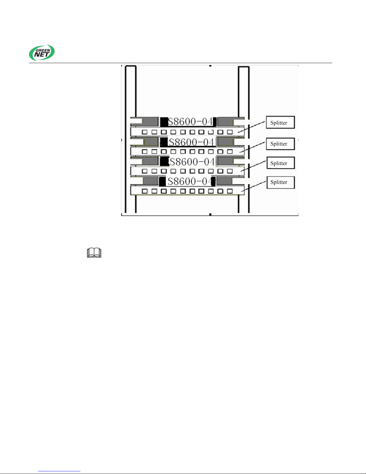
Figure 4-1 Schematic diagram of TiNet S8600-04 GPON OLT installation
The angle bars of the device are not used for load bearing but for
fixing the device. When installed in a cabinet, the device chassis must have
guide rails (fixed to the rack) on its bottom to support the device.
4.1.2 Installing the Device onto a Workbench
In many cases, users do not have a standard 19-inch cabinet, so users
usually place the device on a clean workbench. Installing the device onto a
workbench is relatively simple and requires you to note the following points:
Ensure the workbench is stable and properly grounded.
Leave a 10 cm clearance for cooling around the device.
Do not place heavy objects on the device.
Page 22

Shenzhen New Greennet Technologies Co., Ltd.
3
4.2 Connection of Power Cables and Ground Cables
TiNet S8600-04 GPON OLT is powered by hot swappable power supply box.
It supports both AC and DC hybrid-powered mutual backup mode.
Power supply box falls into two types, respectively AC and DC power supply,
with power supply voltage ranges
AC 176V~ 264V
DC –36V~–72V
4.2.1 AC Power Supply and Installation
1. AC input range
176V~264V,47/63Hz AC
See Figure 4-2 for AC power input socket.
2. AC Power cable connection
Step 1: Plug the AC power supply box into the slot behind S8600-04
Step 2: Insert the power cable into the power outlet on the device chassis rear
panel and the other end into the user-supplied AC power outlet.
4.2.2 DC Power Supply Installation
1. AC input range
176V~264V,47/63Hz AC
See Figure 4-2 for AC power input socket.
2. DC power cable connection
Step 1: Plug the DC power supply box into the slot behind S8600-04
Step 2: Insert the DC power cable into the DC power supply box on the device
chassis rear panel, and for the other end into, please connect the red cord to
the positive pole of DC power supply and the block to the negative.
Page 23
Shenzhen New Greennet Technologies Co., Ltd.
4
4.2.3 Installing the Ground Cable
Grounding the device is an important way of protecting the device
against lightning strikes and interference.
The power input terminal of TiNet S8600-04 GPON OLT is connected with a
noise filter, whose central ground is directly connected to chassis. The chassis
must be well grounded to let induced and leakage electricity safely flow into
the earth, and improve the machine's resistance to electromagnetic
interference. Chassis ground point position is as shown in Figure 2-3.
Connect one end of chassis ground cable accompanied to the device's rear
panel, and the other end shall be well grounded nearby. The grounding
resistance shall be less than 4 Ω. If a device is installed in a standard 19-inch
cabinet, grounding is also compulsory for the cabinet.
4.3 Connecting the Console Cable
4.3.1 Installing the Console Cable
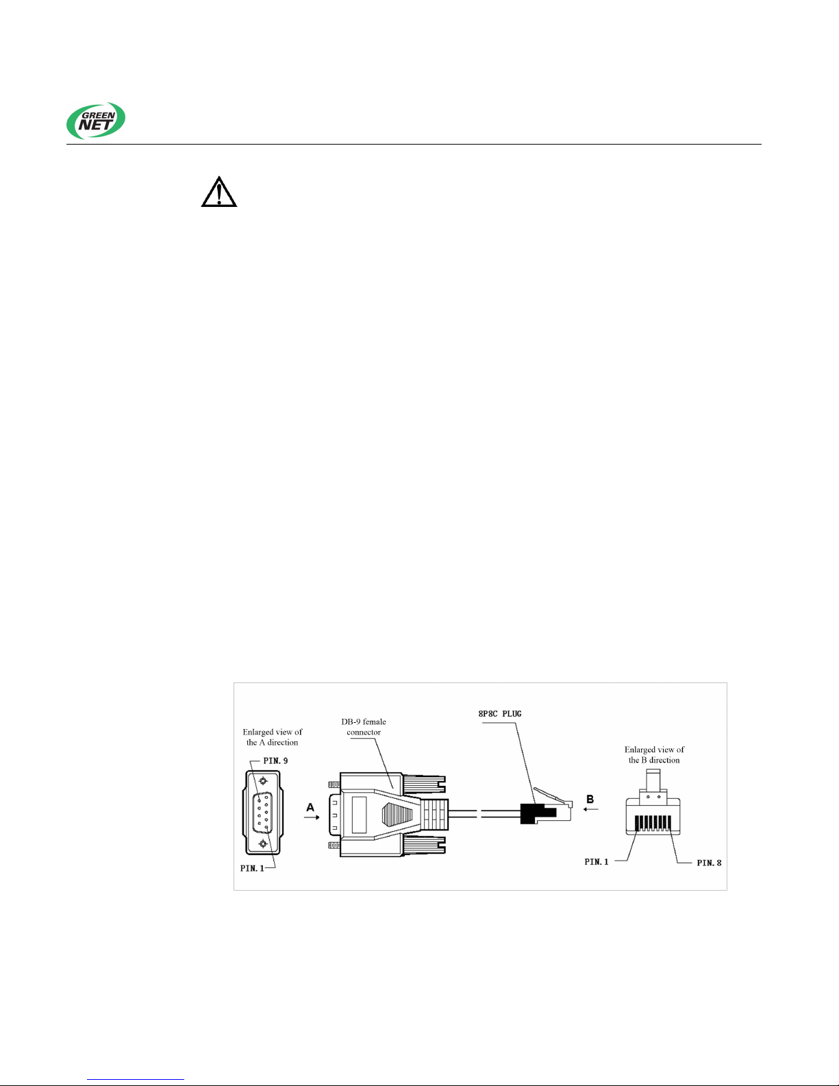
The console cable is an 8-core shielded, with one end connected with RJ-45
plugging into device Console port; and the other end a DB-9 hole-type
connector. Console cable is as shown below:
Figure 4-2 Console cable
Page 24

Shenzhen New Greennet Technologies Co., Ltd.
5
Table 4-1 Console cable connection
RJ45 Signal Direction DB-9
1 CTS → 8
2 DSR → 6
3 RXD → 2
4 GND - 5
5 GND - 5
6 TXD ← 3
7 DTR ← 4
8 RTS ← 7
4.3.2 Connecting the Console Cable
To configure device via terminal, the console cable is connected as follows:
Step 1: Insert the DB-9 connector of the console cable into the serial port of
the PC or terminal where the device is to be configured.
Step 2: Connect one end of console cable’s RJ-45 to device’s console.
Please pay attention to the interface marks to avoid wrong
connection.
4.4 Check after Installation
Check whether the optional power supply is in conformity with the
marked device power supply.
Check whether the ground cable is connected
Check whether the console cable and power input cable are correctly
connected.
Page 25

Shenzhen New Greennet Technologies Co., Ltd.
1
Chapter 5 Start and Configuration
Note: TiNet S8600-04 GPON OLT provides users with two
configuration methods:
Method 1: local terminal configuration. Directly connect the terminal (or
PC) to device's Console via the serial port;
Method 2: terminal Telnet configuration. Configuration terminal is
interconnected with device through IP network. It should be noted that
you need to complete the configuration of device IP address, subnet mask,
and other parameters before employing the terminal Telnet configuration.
5.1 Local Terminal Configuration
5.1.1 Creating a Configuration Environment
Connect the Console port of the device to the terminal (such as a PC) through
a Console cable.
5.1.2 Connecting the Console Cable
Step 1: Insert the DB-9 connector of the console cable into the serial port of
the PC or terminal where the device is to be configured.
Step 2: Connect one end of console cable’s RJ-45 to device’s console.
5.1.3 Setting Terminal Parameters
Step 1: Start the PC and run a terminal simulation program (such as Windows
Operating System HyperTerminal) on the PC.
Step 2: Set terminal parameters (taking parameter setting for the
HyperTerminal in Windows 2000 for example).Parameter requirements: Baud
Page 26
Shenzhen New Greennet Technologies Co., Ltd.
2
rate is "9600", data bit "8", parity check "none", stop bit "1", flow control "none",
and select "auto detection" for terminal simulation. Specific methods are as
follows:
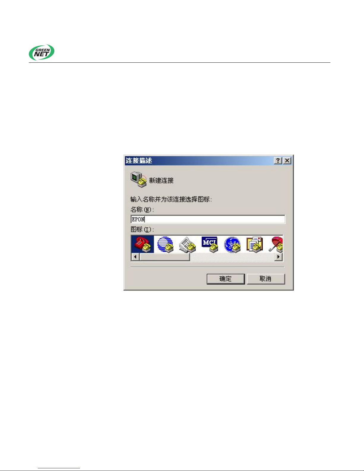
Choose Start > Programs > Accessories > Communication > HyperTerminal
to establish a new connection. The system displays a Connection
Description dialog box, as shown in Figure 5-1. In the Name text box, input a
new name, such as GPON.
Figure 5-1 Connection Description dialog box
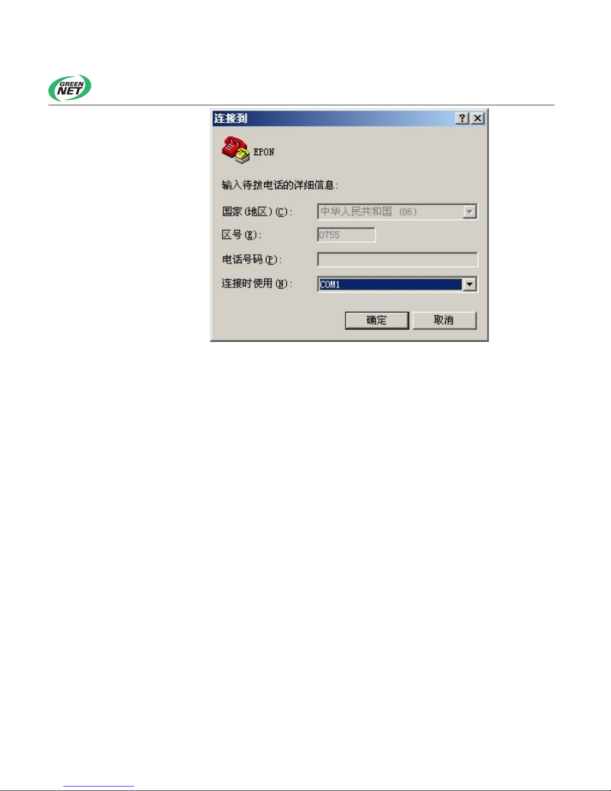
Click OK. The Connect to dialog box pops up, as shown in Figure 5-2. Select
a serial port from the Use in Connecting drop-down list.
Page 27
Shenzhen New Greennet Technologies Co., Ltd.
3
Figure 5-2 Setting of serial port used in HyperTerminal connection
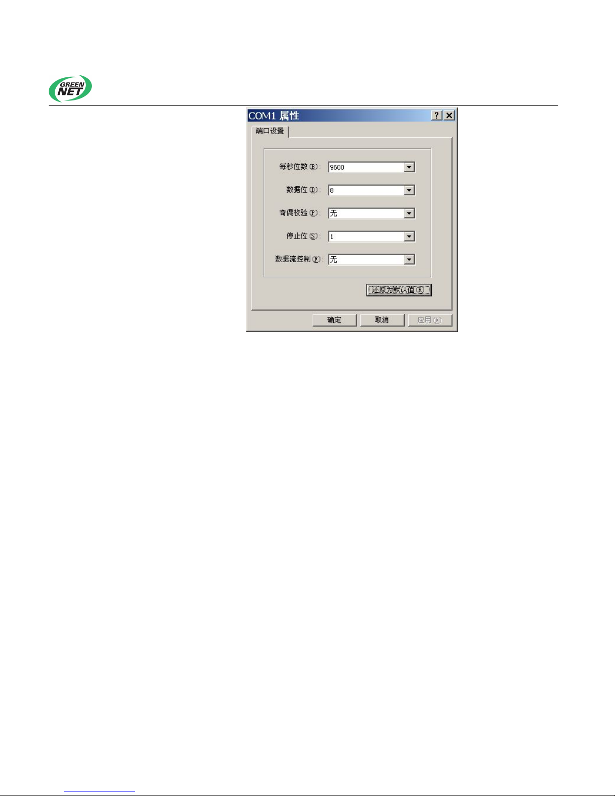
Click OK. A dialog box pops up, as shown in Figure 5-3. In this dialog box, set
the baud rate to 9600, data bit to 8, parity check to None, stop bit to 1, and
flow control to None.
Page 28
Shenzhen New Greennet Technologies Co., Ltd.
4
Figure 5-3 Serial port parameters configuration
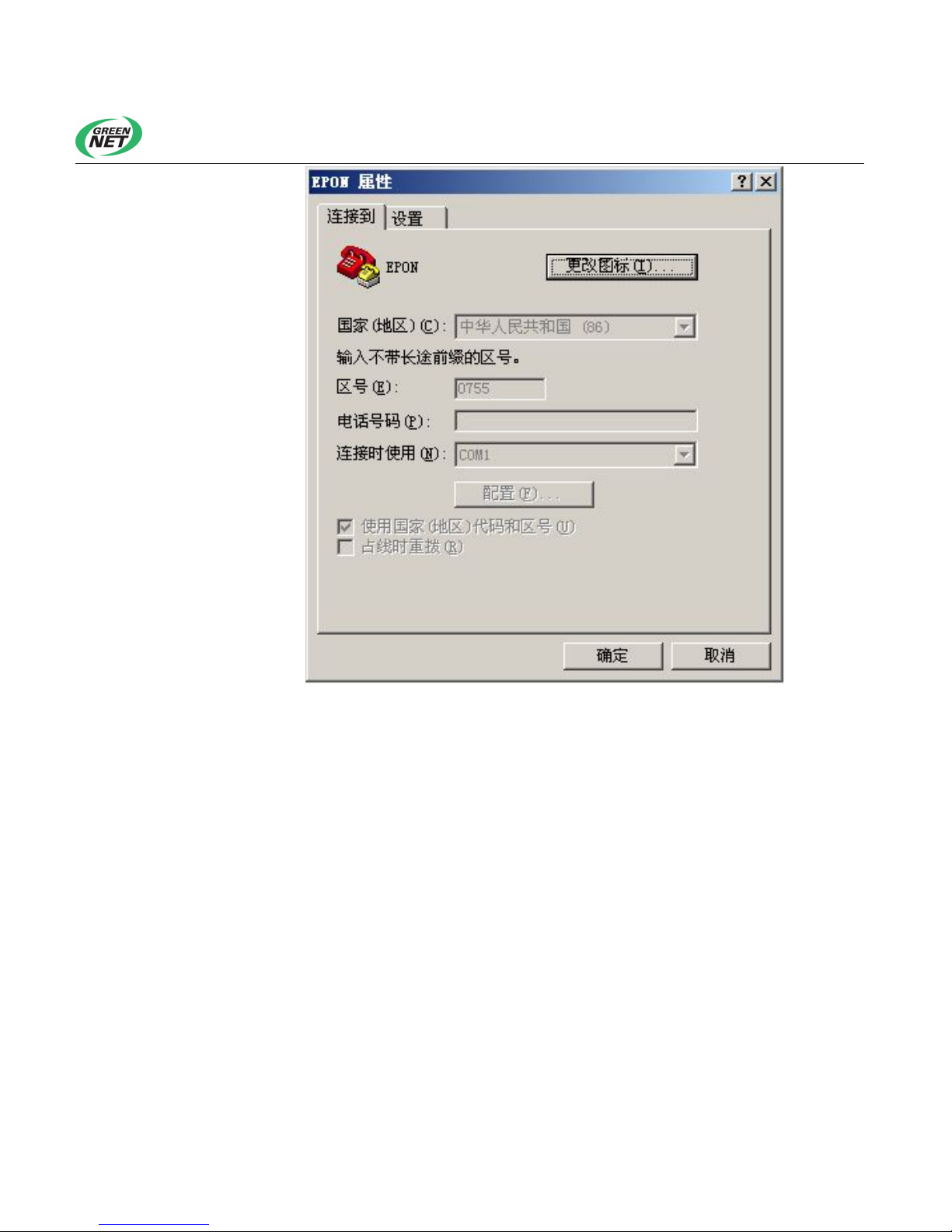
You can also click Configure on the HyperTerminal attribute interface to set
the serial port attributes, as shown in Figure 5-4:
Page 29
Shenzhen New Greennet Technologies Co., Ltd.
5
Figure 5-4 Setting of serial port used In HyperTerminal connection in the attribute setting
window
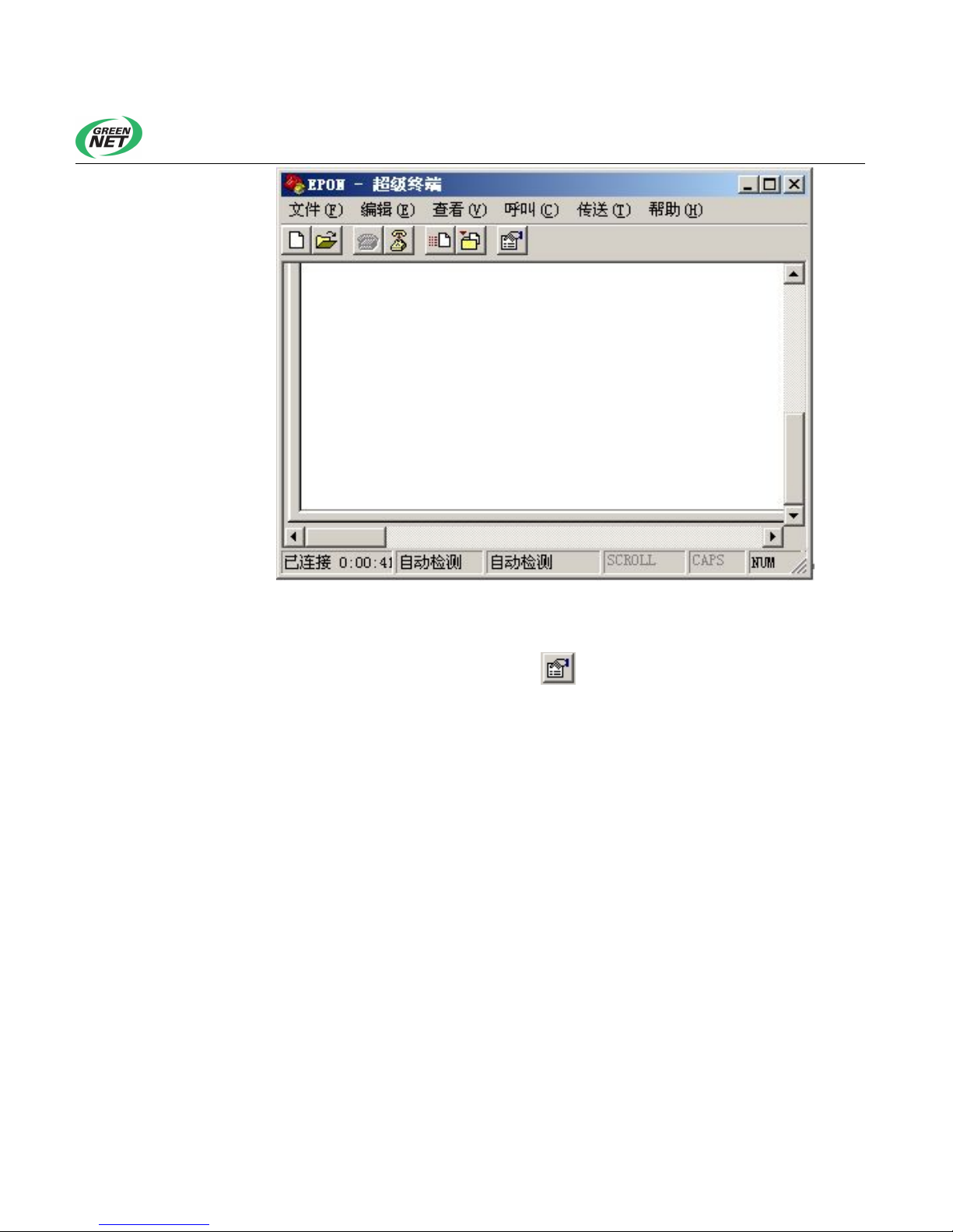
When serial port parameters configuration is completed, click OK to enter the
HyperTerminal interface as shown in Figure 5-5.
Page 30
Shenzhen New Greennet Technologies Co., Ltd.
6
Figure 5-5 HyperTerminal window
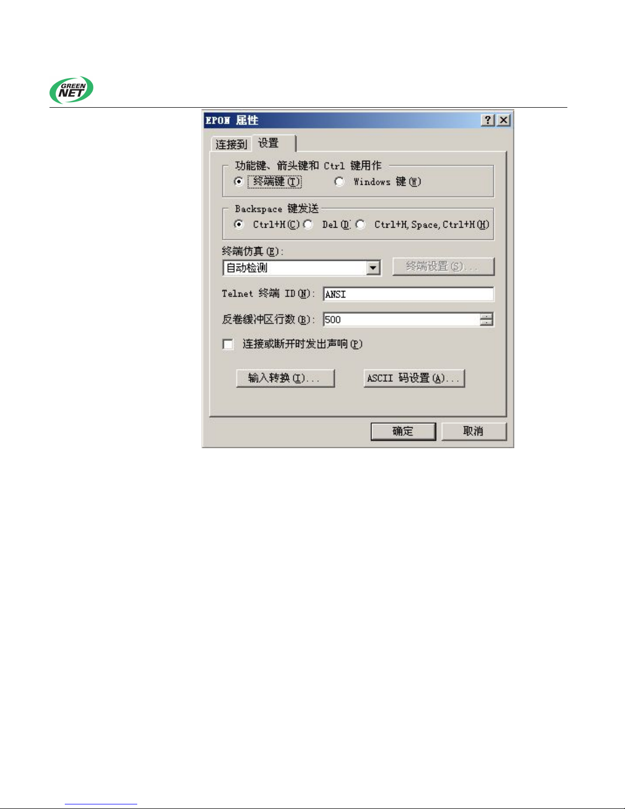
In the HyperTerminal window, select (Attributes) to enter the Attributes
window. Click the Setting tab in the Attributes window to enter the window for
attribute setting (Figure 5-6). In this window, select Auto detection for terminal
simulation, and click OK.
Page 31
Shenzhen New Greennet Technologies Co., Ltd.
7
Figure 5-6 Setting of Terminal Simulation in Attribute Setting window
5.2 Powering On the OLT
5.2.1 Checking the OLT Before Power-on
Before powering on the device, check as follows:
Whether the power cable is connected properly, especially DC power
supply’s positive and negative poles.
Whether the power supply voltage is as required by the device.
Whether the console cable is correctly connected and whether the PC or
terminal used for configuration has been started and set.
Page 32

Shenzhen New Greennet Technologies Co., Ltd.
8
5.2.2 Powering On the Device
When the device is powered on, startup information will be displayed on the
terminal. When the following prompt pops up,
User name(4-15 chars):
You can type a user name, press Enter, and you will be prompted to type
a password, as follows:
Password (1-15 chars):
After typing the password, the HyperTerminal prints the following
information:
QTECH>
At this time, users can view or configure device system information under
their permission.
Page 33

Shenzhen New Greennet Technologies Co., Ltd.
1
Chapter 6 Software Upgrade
Generally software is upgraded through a serial port. This upgrade method,
however, takes a lot of time and requires the engineer to be present in the
machine room or to centralize the OLTs. In addition, only one OLT can be
upgraded at a time. To solve this problem, TiNet S8600-04 GPON OLT allows
users to upgrade applications and download and upload configuration files
online through TFTP.
1. Uploading configuration files via TFTP (see Software Configuration Guide)
2. Downloading configuration files via TFTP (see Software Configuration
Guide)
3. Downloading an application via TFTP
To download an application through TFTP, run the following command:
load application tftp tftp-server filename
An application download can be completed through the following steps:
Step 1: Start the TFTP server and set the destination path of the file to be
downloaded;
Step 2: Enter the command for application download through TFTP.
Assume that you want to download app.arj from the PC whose IP address is
192.168.0.100.
Start the TFTP server on the PC, set the file path, and then enter the following
in privileged mode:
QTECH#load application tftp 192.168.0.100 app.arj
Upon a successful download, a message is prompted as follows:
Application file has been downloaded via tftp successfully.
The new application will not be effective until the device is rebooted.
Page 34

Shenzhen New Greennet Technologies Co., Ltd.
2
When the download is successful, the application will be available
in the next startup!
Page 35

Shenzhen New Greennet Technologies Co., Ltd.
1
Chapter 7 Troubleshooting
7.1 Power Supply System Failure
TiNet S8600-04 GPON OLT can determine whether the device power supply
system is in failure according to the Power Indicator on the front panel: Power
Indicator stays on when the Power system is operating normally; when the
Power Indicator is not lit, please do the following check:
Whether the device power cable is connected correctly.
Whether the device power supply is as required.
Whether the power switch is turned on.
7.2 Configuration System Failure
When TiNet S8600-04 GPON OLT is powered on, the startup information will
be displayed on the configuration terminal if the system is in normal operation;
If the configuration system is faulty, no information will be displayed or garbled
characters are displayed.
7.2.1 No Terminal Display
When powered on, you have to do the following checks if the configuration
terminal displays nothing:
Check whether the power supply is normal.
Whether the console cable is properly connected
If no problems are found, errors are prone to exist in console cable or terminal
(such as HyperTerminal) settings, please make the appropriate checks.
Page 36

Shenzhen New Greennet Technologies Co., Ltd.
2
7.2.2 Garbled Characters
If garbled characters are displayed on the configuration terminal, a terminal
(such as a HyperTerminal) may encounter a setting error. Check and verify
that the terminal (such as a HyperTerminal) parameter settings are as follows:
Baud rate: 9600
Data bit: 8
Parity check: none
Stop bit: 1
Flow control: none
Auto detection for terminal simulation.
Page 37

OptiWay GL5600-08P V100R001 Cassette OLT Installation Manual V1.0 (20130419) Installation Manual
3
Chapter 8 Appendix RJ-45 Connector
8.1 RJ-45 Connector
The 1000Base-TX port and the port for commission of TiNet S8600-04 GPON
OLT fit for the RJ-45 connector.
Figure 9-1 shows the standard RJ-45 socket and connector of a cable
between a device and a network adapter, as well as the pins of the RJ-45
connector.
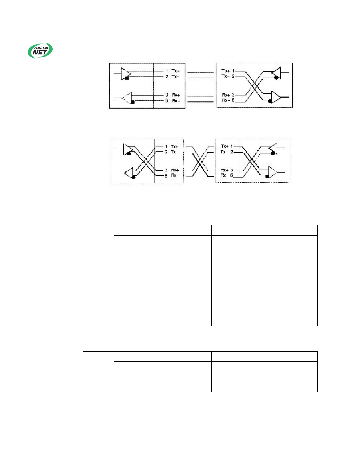
Figure 9-2 and Figure 9-3 show how to connect a cable in parallel and
crossover modes.
Table 9-1 shows the electrical characteristics of pins of an RJ-45 connector in
MDI mode.
Table 9-2 shows the electrical characteristics of pins of an RJ-45 connector in
MDI-X mode.
Figure 8-1 Standard RJ-45 socket and connector
Page 38
OptiWay GL5600-08P V100R001 Cassette OLT Installation Manual V1.0 (20130419) Installation Manual
4
Figure 8-2 Parallel mode
Figure 8-3 Crossover mode
Table 8-2 Assignment of pins of an RJ-45 MDI port
Pin No.
10/100Base-T 1000Base-T
Signal Function Signal Function
1 Tx+ Sending data BIDA+ A-direction data
2 Tx- Sending data BIDA- A-direction data
3 Rx+ Receiving data BIDB+ B-direction data
4 Reserved - BIDB- B-direction data
5 Reserved - BIDC+ C-direction data
6 Rx- Receiving data BIDC- C-direction data
7 Reserved - BIDD+ D-direction data
8 Reserved - BIDD- D-direction data
Table 8-3 RJ-45 Assignment of pins of the MDI-X port
Pin No.
10/100Base-T 1000Base-T
Signal Function Signal Function
1 Rx+ Receiving data BIDB+ B-direction data
2 Rx- Receiving data BIDB- B-direction data
Page 39
OptiWay GL5600-08P V100R001 Cassette OLT Installation Manual V1.0 (20130419) Installation Manual
5
Pin No.
10/100Base-T 1000Base-T
Signal Function Signal Function
3 Tx+ Sending data BIDA+ A-direction data
4 Reserved - BIDC+ C-direction data
5 Reserved - BIDC- C-direction data
6 Tx- Sending data BIDA- A-direction data
7 Reserved - BIDD+ D-direction data
8 Reserved - BIDD- D-direction data
8.2 Cable Making
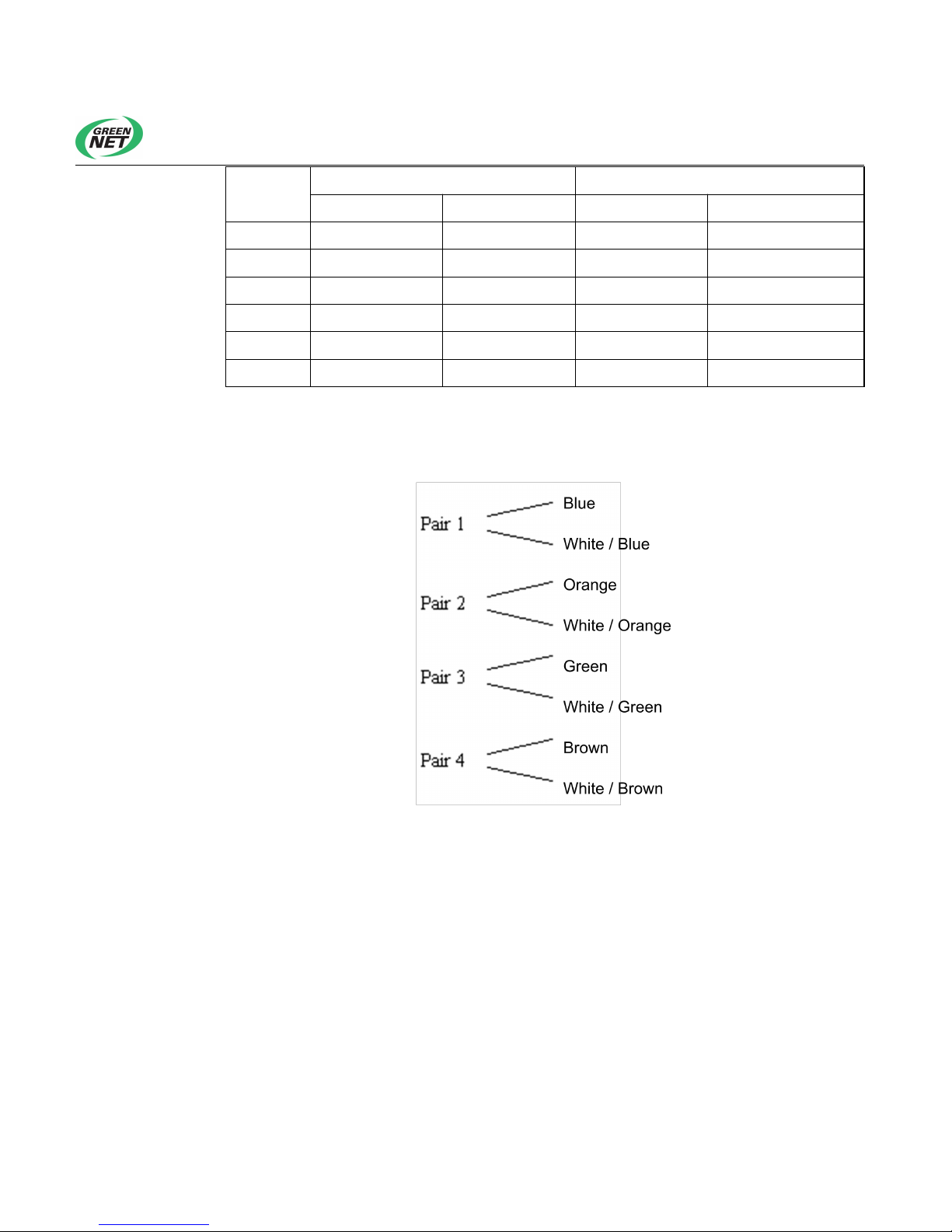
Figure 8-4 Category 5 twisted-pair cable
The above figure shows an example of making an Ethernet cable with an
RJ-45 connector out of a Category 5 twisted-pair cable. It is for reference only.
A category 5 twisted-pair cable consists of 8 wires, which are identified and
grouped according to the colors of their insulation layers. Usually two wires in
different colors as well as the wire in white form a pair or wires are paired
based on color dots. The former method is adopted in this example.
Page 40

OptiWay GL5600-08P V100R001 Cassette OLT Installation Manual V1.0 (20130419) Installation Manual
6
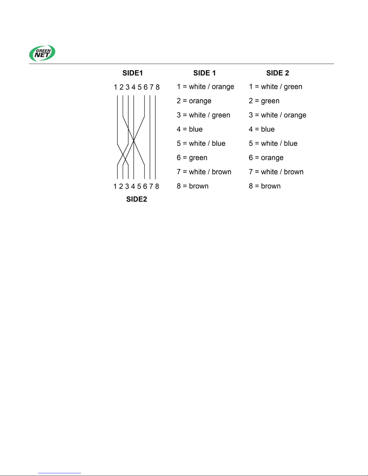
Wires of a straight-through cable and a crossover cable are arranged
respectively as follows. Users may select a cable type according to their own
needs. In a traditional network, a straight-through cable connects a network
adapter and a hub or device, while a crossover cable connects device or a
device and a hub or router. "SIDE1" and "SIDE2" in the figure represent the
two ends of a cable, and numbers 1 to 8 indicate the eight pins of an RJ-45
connector.
Figure 8-5 Making of a straight-through cable
Page 41
OptiWay GL5600-08P V100R001 Cassette OLT Installation Manual V1.0 (20130419) Installation Manual
7
Figure 8-6 Example of crossover cable production
 Loading...