

Page 1
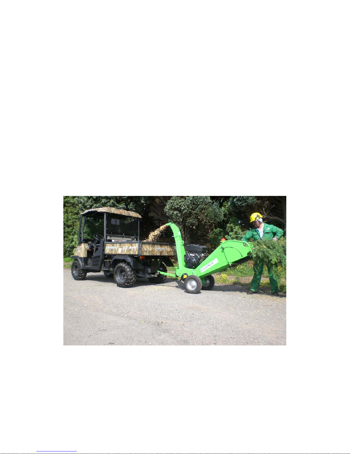
CS 100
COMPACT 4-INCH
CHIPPER
Operator’s Manual
Page 2

CS 100 CONTENTS 1
SECTION:
1. Introduction and Purpose
2. Technical Specifications, Dimensions, Noise Level, and
Lifting points
3. Safety and Symbols
3.1 Ensure!
3.2 Never!
3.3 Always!
3.4 Safety controls and switches
3.5 Control cut-outs
3.6 Symbols
4. Machine Preparation
4.1 Fuelling and parking
4.2 Infeed chute
4.3 Discharge chute
5. Operation
5.1 Pre-work checks
5.2 Starting machine
5.3 Stopping machine
5.4 Operating Hints
5.5 Preparing for Transport on completion of work
6. Maintenance
6.1 Routine Maintenance schedule and lubrication points
6.2 Engine Oil
6.3 Fuel level
6.4 Air cleaner
6.5 Drive belts
6.6 Infeed Chute Flaps
6.7 Cutting unit
6.8 Steam cleaning
6.9 Wheels and Tyres
6.10 Bearings and pivots
6.11 Mountings
7. Storage
7.1 Storage
7.2 Removal from storage
©GreenMechLtd - 1 - 06/09
Page 3

CS 100 CONTENTS 2
8. Disposal
9. Appendix
9.1 Certificate of Conformity
9.2 Risk Assessment
9.3 Noise Assessment
9.4 Parts List
9.5 Transcript of HSE leaflet 604
©GreenMechLtd - 2 - 06/09
Page 4
GM C/S100 1. INTRODUCTION AND PURPOSE 1-1
INTRODUCTION
This manual explains the proper operation of your machine. Read these instructions
thoroughly before operating and maintaining the machine. Failure to do so could result in
personal injury or equipment damage. Consult your GreenMech supplier if you do not
understand the instructions in this manual.
CAUTION! This symbol indicates important safety messages in this manual.
When you see this symbol, be alert to the possibility of injury to yourself or
others, and carefully read the message that follows.
We recommend that you keep this manual with the machine in the box provided. Note
here the serial number and quote it in any communications. This is important when
ordering spares. Remember to include all numbers and letters.
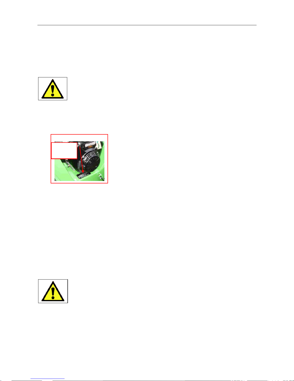
VIN Number…………………………………
Serial Number............................................
Write in the number!
Fig 1.1 Serial Number
Serial
Number
This manual covers the following models.
GM C/S100 Compact Chipper/ Shredder with interchangeable cassettes
Optional 14HP or 18HP (electric start) Briggs and Stratton Vanguard engines
The information in this manual is correct at the time of publication. However, in the course
of development, changes to the machine specification are inevitable. Should you find any
information to vary from the machine in your possession please contact your GreenMech
dealer for up to date information.
The manual may contain standard and optional features and is not to be used as a
machine specification.
PURPOSE
CAUTION! This machine is designed solely to chip wood and must not be
used for any other purpose. The machine should only be used by trained
operators who are familiar with the content of this instruction manual. It is
potentially hazardous to fit or use any parts other than genuine GreenMech
parts. The company disclaims all liability for the consequences of such use,
which in addition voids the machine warranty.
©GreenMechLtd 1-1 11/09
Page 5
GM C/S100 2. SPECIFICATIONS 2-1
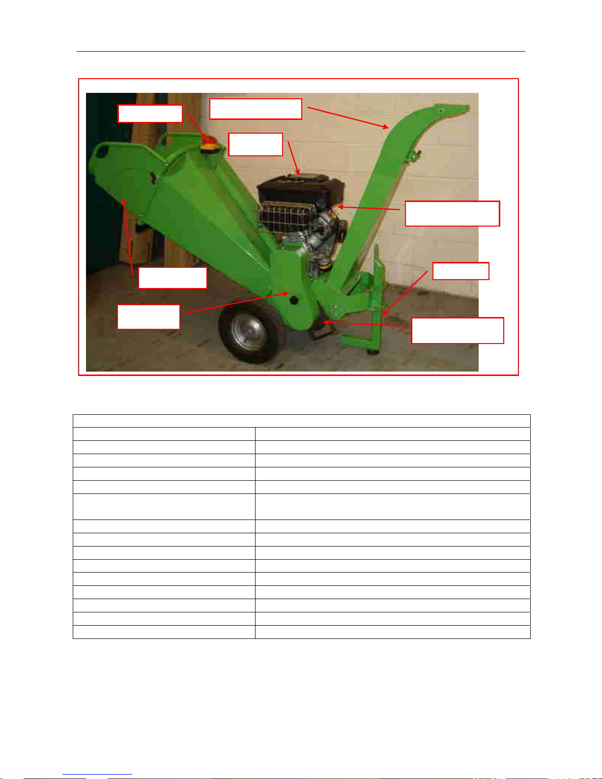
Fig 2.1 GM C/S100 Main Features
Engine controls
Drive cover
Stop Button
Infeed chute
Chipper cassette
Discharge chute
Fuel tank
Stand
TECHNICAL SPECIFICATION GM C/S100-14 / GM C/S100-18
Chipping Capacity 4 to 6 m3 cuttings per hr depending on material
Guaranteed wood diameter 80mm (3”)
Permitted wood diameter 130mm (5”)
Chipping Blades 2 reversible and regrindable blades
Rotor cutting width 310mm
Power Unit Briggs and Stratton 4 stroke Vanguard V Twin 14hp
or 18hp with electric start
Fuel Petrol 95 octane (unleaded)
Fuel Consumption (continuous) 2 8 lt/hour
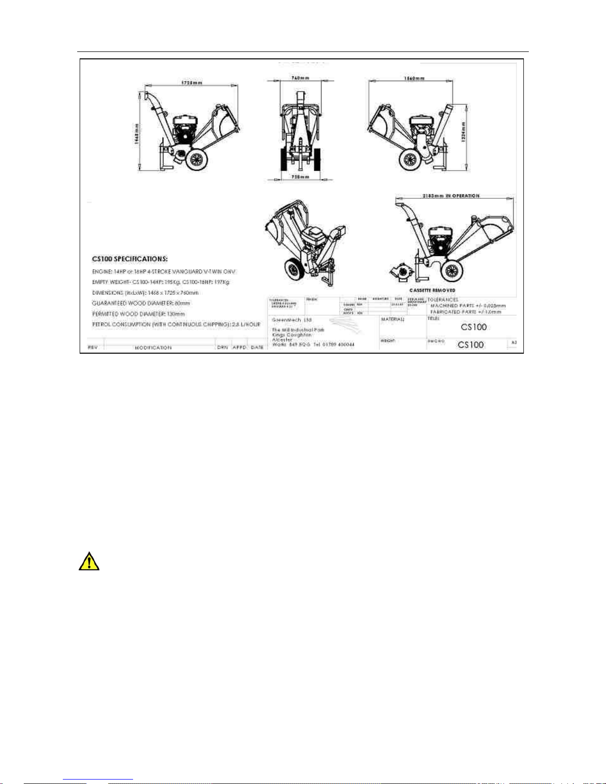
Length (Transport) 1725mm
Length (Work) 2183mm
Width 760mm
Height (Transport) 1245mm
Height (Work) 1468mm
Feed Height 840mm
Weight (Empty) 195Kg / 197Kg
©GreenMechLtd 2-1 11/09
Page 6
GM C/S100 2. SPECIFICATIONS 2-2
Noise
Noise levels vary depending on type of material being processed. Also duration of
operation is variable. Noise emission tests have been carried out and the guaranteed
sound power level is displayed on the CE plate as follows: Lwa 120dB(A)
Minimise noise by slowing to idle or stopping the engine whenever chipping is not in
progress.
Full details are included in the Risk Assessment in the Appendix.
CAUTION! Operators must wear appropriate ear protection. Bystanders must be
kept away from proximity of machine.
Lifting Points
Ensure infeed chute is folded in and secured for transport. Sling from tubular handles of
fixed section of infeed chute and lifting point on discharge chute.
©GreenMechLtd 2-2 11/09
Page 7
GM C/S100 3. SAFETY 3-1
3.1 ENSURE:
3.1.1 All Operators must be fully trained in
the use of their machine.
(Certificated Operator training courses are
available on request.)
3.1.2 The Operators Manual is read and
understood.
3.1.3 The enclosed HSE guidance notes
are read and understood.
3.1.4 The machine is positioned on level
ground and the machine must be level with
the infeed chute at no less than 600mm
(23.62 inches) above ground level (fig
3.4.3).
3.1.5 All guards are fitted and in good
condition.
3.1.6 Blades are in good condition and
secure.
3.1.7 All blades are sharpened or replaced
in “Sets”.
3.1.8 All fasteners are checked regularly
for tightness.
3.1.9 Only “WOODEN” materials free of
nails etc., are fed into the machine.
3.1.10 Correct First Aid Kit including large
wound dressing is available on site.
3.1.11 Fire extinguisher is available on site.
3.2 NEVER:
3.2.1 Work on the machine until the
chipper disc is stationary and engine has
stopped.
3.2.2 Operate the machine without
protective clothing (Eye protection,
Earmuffs, and Gloves), or high visibility
clothing when working on roadside.
3.2.3 Operate with loose articles of
clothing, including loose cuffs on gloves.
3.2.4 Work under a raised component
without adequate safety support.
3.2.5 Operate the machine with untrained
personnel or with individuals present who
are not involved in the chipping operation.
3.2.6 Leave the machine unattended with
engine running at full operating speed.
(See section 4)
3.2.7 Put any part of your body into the
infeed chute while the machine is running.
3.2.8 Operate the machine whilst under the
influence of alcohol or drugs.
3.2.9 Operate inside a building or confined
space.
3.2.10 Climb on the infeed chute.
3.3 ALWAYS:
3.3.1 Check machine before starting (see
Section 4 Preparation and Section 5.1
Operation: Pre-work checks).
3.3.2 Be aware of potential hazards in the
work area, i.e. uneven ground, tree roots,
trip/slip hazards, obstructions and type of
materials being fed into the machine.
3.3.3 Feed from the side.
3.3.4 Have a second trained operator
within easy reach of the machine.
3.3.5 Maintain strict discipline at all times.
3.3.6 Service machine at specified periods.
(see Section 6: Routine Maintenance).
3.3.7 Note direction of discharge chute and
if necessary note the wind direction to
prevent debris from being blown into
highway or where it could affect members
of the public.
3.3.8 Remove key before doing any
maintenance.
©GreenMechLtd 3-1 11/09
Page 8
GM C/S100 3. SAFETY 3-2
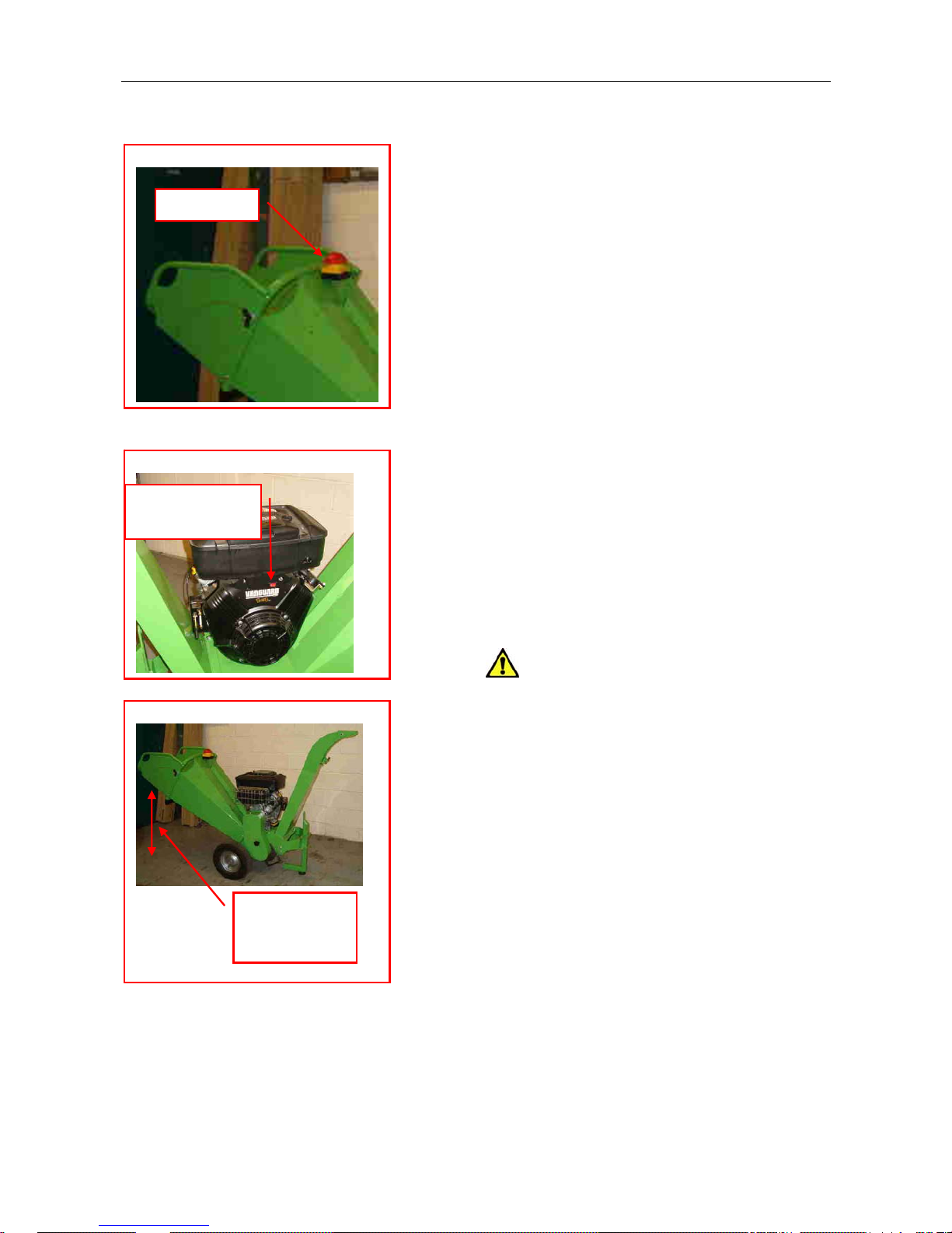
Fig 3.4.1 Stop Button
Stop Button
3.4 Safety Controls and Switches
3.4.1 Emergency Stop (fig 3.4.1)
In the event of an emergency, push the
STOP button. This will lock in position to
stop the engine and machine.
3.4.1.1 Once the emergency has been
rectified the following sequence should be
carried out:
3.4.1.2 Check over machine for any
blockages.
3.4.1.3 To reverse the cutter, remove the
drive guard and, using a bar through the
hole in the cutter spindle, manually turn the
cutter to free the obstruction.
Fig 3.4.2 Engine Stop Switch
Stop switch or
key (elec start)
3.4.1.4 When clear, pull the stop button out
and restart the engine.
3.4.2 Engine stop switch
3.4.2.1 To stop the engine, push the cut-off
switch to the ‘0’ position. (fig 3.4.2), or
(electric start) turn key switch anticlockwise.
CAUTION! Do not restart engine until
hazard has been removed.
Fig 3.4.3 Infeed chute height
Infeed chute
height 600mm
min. (24")
3.5 Control cut-outs
An engine cut-out is installed under the
drive guard to stop and prevent restarting.
due to specific events. The drive guard has
to be removed first to access the cutter or
dismantle the chutes
©GreenMechLtd 3-2 11/09
Page 9
GM C/S100 3. SAFETY 3-3
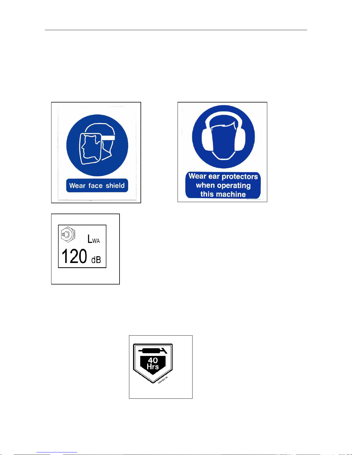
3.6 SYMBOLS on the MACHINE
These relate to operator safety, correct use and maintenance of machine. Check that all
personnel understand and are familiar with meanings before using the machine.
See engine manual for safety and control symbols on the engine.
Important Safety symbols
Take the correct action shown on the display below the stated hazard (see table)
Sound level
Ear defenders must be
worn
Important Operating Checks.
See engine manual.
Maintenance Information
See engine manual
Grease point
40 hours / weekly
©GreenMechLtd 3-3 11/09
Page 10
CS 100 4. MACHINE PREPARATION 4-1
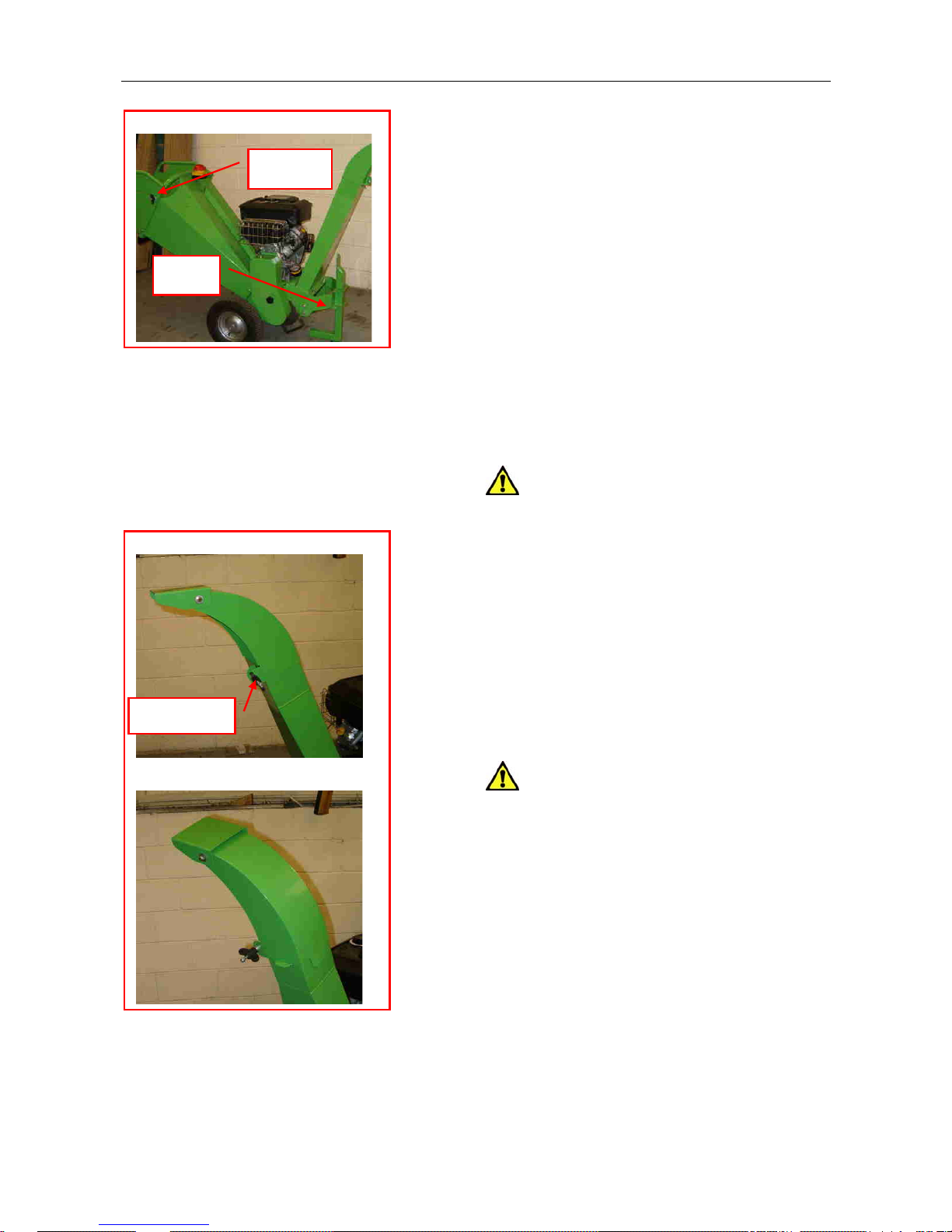
Fig 4.1 Stand and Infeed Chute
4.1 Initial Fuelling and Parking
4.1.1 Position the machine on level ground
and ensure stand is secure (fig 4.1).
Hand nut
4.1.2 Fill the fuel tank with petrol.
4.1.3 Check the engine oil level.
4.1.4 Check that the stop button is
released.
Stand
4.2 Infeed Chute
4.2.1 Loosen hand nuts (fig 4.1) and swing
the infeed chute extension into work
position.
4.2.2 Tighten hand nuts ensuring that
nylon spacers pass through holes at ends
of slot.
.
CAUTION! Before transporting,
always fold up and secure the infeed chute.
Fig 4.3 Discharge Chute
Alternative position (either side)
4.3 Discharge Chute (Fig 4.3)
4.3.1 Release the spout clamp, remove
and reset the spout in the desired direction
and tighten the clamp.
Spout clamp
4.3.2 Set the flap at the desired height.
CAUTION! Observe wind direction -
avoid danger of discharge blowing towards
operator.
©GreenMechLtd 4-1 06/09
Page 11
GM C/S100 5. OPERATION 5-1
5.1 Pre-Work Checks:
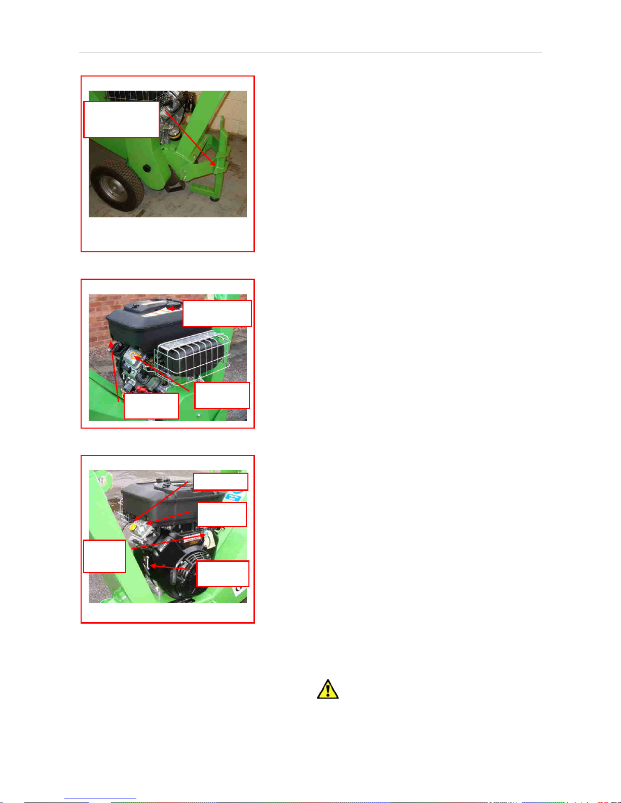
5.1.1 Check machine is stable with support
stand lowered with pin in place (fig 5.1.1).
Fig 5.1.1 Support Stand
5.1.3 Check engine oil level (fig 5.1.2 - See
also 6.2 and Engine instruction manual).
Support stand
and pin
5.1.4 Check engine air filter. (see Section
6.4)
5.1.5 Check fasteners for tightness.
5.1.6 Check cutter is free to turn.
5.1.6.1 If blocked, remove the drive guard
and, using a bar through the hole in the
cutter spindle, manually turn the cutter until
free of obstruction.
5.1.6.2 Check tightness of blade bolts and
condition of blades. See 6.7 for cutter
blade servicing.
5.1.6.3 Remove any loose material.
Fig 5.1.2 Engine Oil and Fuel
5.1.7 If any bolts are loose, refer to
maintenance section for further action.
Fuel Filler
5.1.8 Check discharge chute and flap is in
desired position and all clamps are tight.
(see Section 4.3)
5.1.9 Check infeed chute is folded out.
5.1.10 Check infeed rubber flaps are intact.
5.1.11 Check work area and erect signs
and cone off discharge area if necessary.
5.1.12 Check ALL safety procedures have
been followed.
5.2 Starting Machine:
5.2.1 Check all other personnel are clear of
machine.
5.2.2 Check that machine stop button is pulled
out to start.
5.2.3 Turn engine start switch to position I. (fig
5.2)
5.2.4 Open fuel tap by putting the vane to
vertical.
5.2.5 Set throttle to Slow and pull out choke.
5.2.6 Turn key or pull starter cord to start
engine.
5.2.7 Push choke back in.
5.2.8 Set throttle to Fast.
5.3 Stopping Machine
5.3.1 Push the STOP button.
5.3.2 Switch start key to position 0.
5.3.4 Wait for engine and cutter to stop.
CAUTION! The cutter may take
several seconds to stop due to its inertia.
Fuel tap
Dipstick
Fig 5.2 Engine controls
Start Stop
Throttle
Choke
Oil Filler
©GreenMechLtd 5-1 11/09
Page 12
GM C/S100 5. OPERATION 5-2
5.4 Operating Hints
5.4.1 Reduce the engine throttle to Slow
whilst further material is collected for
chipping.
5.4.2 Take care when feeding wood into
the machine to allow for awkward shapes to
“KICK” when contacting the cutter.
CAUTION! Do not adjust discharge
chute when chipping is in progress.
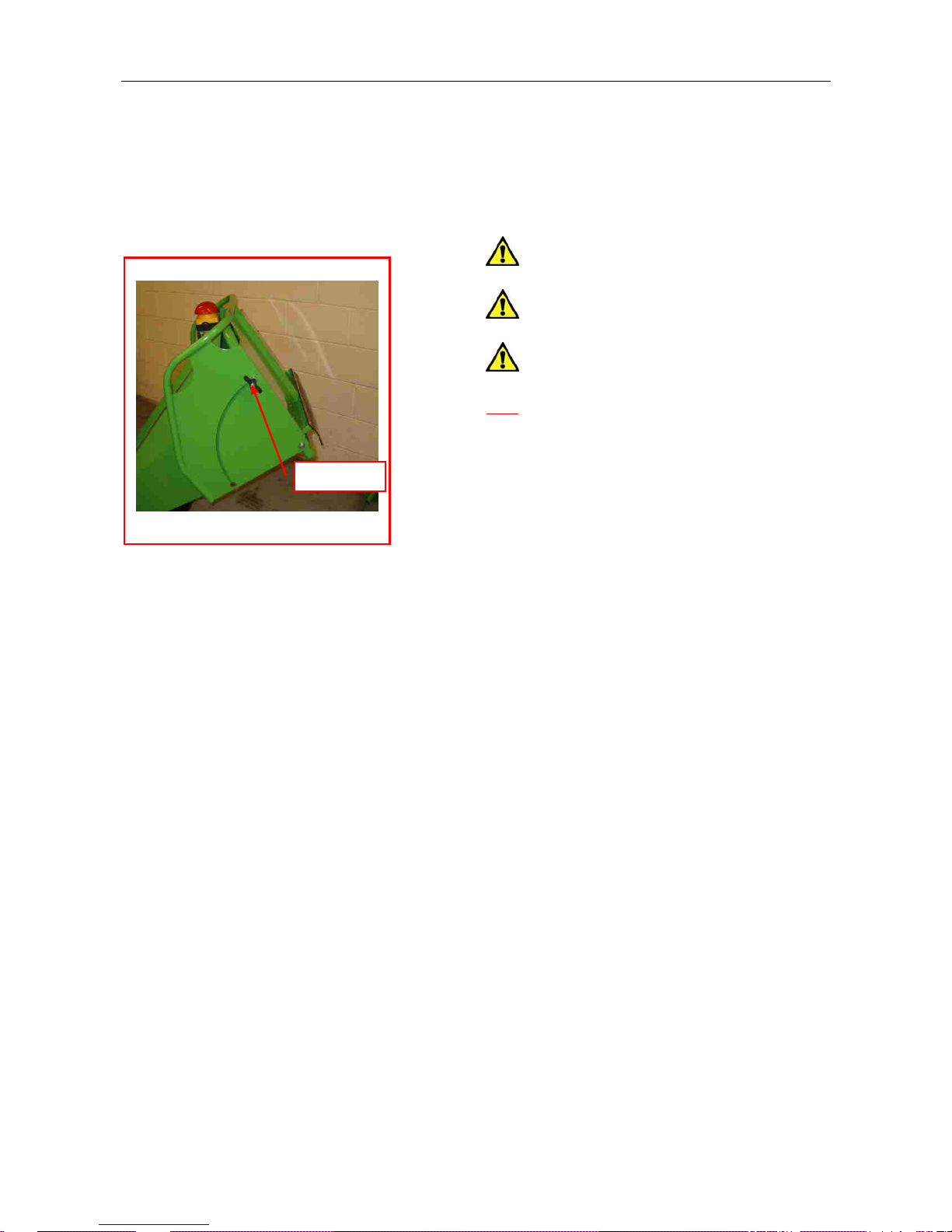
Fig 5.5 Infeed chute folded in
CAUTION! A build up of debris risks
overheating of the engine and a risk of fire.
CAUTION! Keep working area around
the machine clear at all times and check
only authorised personnel are present.
Hand nut
5.5 Preparing For Transport On
Completion Of Work
5.5.1 Check that engine has stopped and
cutter is stationary.
5.5.2 Shake the machine and remove
surplus material from infeed chute and
machine surfaces.
5.5.3 Lift up infeed chute to transport
position and secure with hand nuts (fig 5.5)
ensuring spacers pass through holes at
ends of slots.
©GreenMechLtd 5-2 11/09
Page 13

GM C/S100 6. MAINTENANCE 6-1
ROUTINE MAINTENANCE SCHEDULE
CAUTION! Always press stop button, switch engine to 0 and check for rotation before
carrying out any maintenance.
Action Section Page
DAILY
Check engine oil level (ref: engine manual) 6.2 – 6.3 6-3
Check fuel level 6.2 6-3
Clean air cleaner 6.4 6-3
Check drive belt 6.5 6-3
Check condition of infeed chute rubber flaps 6.6 6-3
Check condition of cutter blades and retaining bolts 6.7 6-4
First 50 hours
Check drive belt tension 6.5 6-3
Check wheel and tyre condition and pressures 6.9 6-5
Check all mountings 6.11 6-5
Check battery levels 6.12 6-5
Service engine Refer to engine manual
Weekly in addition to Daily actions
Check drive belt tension 6.5 6-3
Steam clean machine 6.8 6-5
Clean air cleaner 6.4 6-3
Check wheel and tyre condition and pressures 6.9 6-5
Grease all bearings and pivots 6.10, 6.1 6-5
Check all mountings 6.11 6-5
Check battery levels 6.12 6-5
250 hours in addition to Daily and Weekly actions
Check condition of bearings and pivots 6.10 6-5
Service engine Refer to engine manual
Check axle mounting bolts for tightness 6.11 6-5
Check and grease wheel spindles 6.10 6-5
ENGINE MAINTENANCE REFER TO ENGINE MANUAL
Tyre Pressure 1.4 bar (20 lb/in
2
)
Recommended lubricants Specification
Grease Complex grease EP2 (high temperature)
Engine SAE 15W-40 APICD
©GreenMechLtd 6-1 11/09
Page 14
GM C/S100 6. MAINTENANCE 6-2
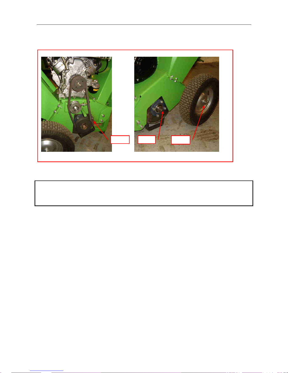
6.1 Lubrication Points (see 6.14)
Fig 6.1 Lubrication points GM C/S100
6.1.2 6.1.36.1.1
Grease except where stated
6.1.1 Cutter bearing (remove guard) 1 nipple
6.1.2 Cutter bearing (non-drive end) 1 nipple
6.1.3 Wheel spindles Remove wheel - smear with grease
Note. Do not overgrease bearings as damage to seals may occur.
©GreenMechLtd 6-2 11/09
Page 15
GM C/S100 6. MAINTENANCE 6-3
6.2 Engine Oil
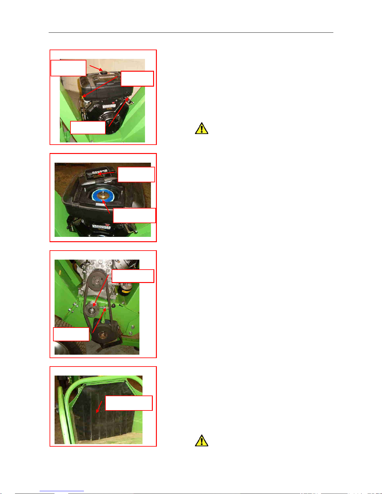
6.2.1 Check daily (fig 6.2). Refer to
engine manual to refill.
Fig. 6.2 Engine Dipstick and Filler
Engine Oil Filter
Fuel Filler
Refer to engine manual for replacement.
Oil Filler
6.3 Fuel Level
6.3.1 Check daily before work and fill as
required (fig 6.2).
CAUTION! Use clean 4-stroke petrol
fuel only. If in doubt, use a funnel with a
filter.
Dipstick
Fig. 6.4 Engine Air Cleaner
6.4 Air Cleaner
Weekly
Cover
6.4.1 Remove cover (fig 6.4).
6.4.2 Unscrew nut to slide out element and
either blow out with air-line or gently tap on
smooth ground to release debris.
6.4.3 Replace element and cover.
Air Cleaner
6.4.4 Ensure hand nuts are secure.
6.5 Drive Belts (Fig 6.5)
Check daily, before work.
6.5.1 Remove guard and inspect.
Fig 6.5 Drive Belt
Tension
Desired belt tension is 400N.
Pulley Bolt
6.5.2 Check with tension meter (available
as an option.)
6.5.3 Release pulley bolt and adjust
locknuts on tensioning screw to set tension.
6.5.4 Tighten pulley bolt.
Replacement
6.5.5 Release pulley bolt and slacken
tensioning screw to allow belts to be
removed.
Tensioner
6.5.6 Fit new belts, ensuring they lie snugly
in the pulley grooves.
6.5.7 Tension belts, tighten pulley bolt and
replace guard securely.
Fig. 6.6 Infeed Chute Rubber Flaps
Note: Re-tension new belts after 5
working hours.
Rubber Flaps
6.6 Infeed Chute Flaps (Fig 6.6)
Two slitted flaps protect the operator from
material thrown back up the infeed chute.
6.6.1 Replace flaps if damaged.
CAUTION! Do not operate with
missing or damaged flaps.
©GreenMechLtd 6-3 11/09
Page 16
GM C/S100 6. MAINTENANCE 6-4
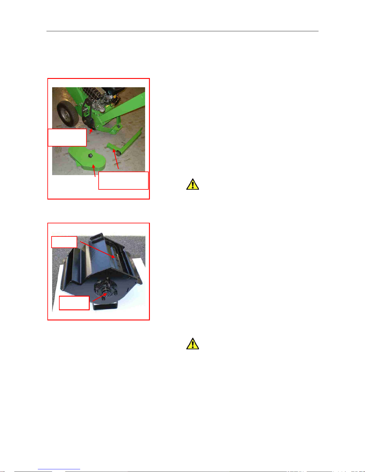
6.7 Cutter Blade Servicing
The cutter cassette is removed as a unit to
service the cutter blades.
Cassette removal (fig 6.7.1)
6.7.1 Check engine is switched off.
6.7.2 Remove drive belts as 6.5 above
Fig 6.7.1 Cassette Removal
6.7.3 Fold the infeed chute in for transport
and secure.
6.7.4 Tip machine back onto infeed chute
and remove stand.
6.7.5 Tip machine forward to rest on feet of
cassette.
Cassette
on fe
6.7.6 Remove 2 front bolts and 2 rear
bolts.
6.7.7 Carefully tilt machine back to release
cassette and rest machine on infeed chute.
et
Blade servicing (Fig 6.7.2)
Drive guard and
stand removed
CAUTION! Take care. Blades are
extremely sharp.
6.7.8 Slacken blades bolts with Torx tool
supplied and remove.
6.7.9 Turn blades round and refit to use
opposite edge.
Fig 6.7.2 Blade removal
6.7.10 Tighten blade bolts to 35Nm.
6.7.11 Check clearance to anvil is 0.5mm.
Blade
Note: If blades have been reground the
anvil will need readjusting to 0.5mm.
6.7.12 Reassemble cassette and refit to
machine by reversing procedure above.
6.7.13 Refit belts as 6.5 above.
6.7.14 Replace and secure drive guard.
Blade regrinding
Bearing
Both edges of each blade must be ground
on front at 27˚ angle and on back 10˚ angle
over 4mm to ensure correct clearances.
When less than 48mm minimum width
blades may be raised by a suitable shim.
CAUTION! Blades must only be
sharpened by grinding on a bench grinder.
Do not sharpen with hand held equipment.
Always sharpen in sets to maintain balance
of cutter assembly.
©GreenMechLtd 6-4 11/09
Page 17
GM C/S100 6. MAINTENANCE 6-5
6.8 Steam Cleaning
weekly and every 250 hours
6.8.1 Check all covers are fitted and
closed
6.8.2 Steam clean machine surfaces.
6.8.3 Clean electrical components with a
damp rag, spray with WD40 and then wipe
with dry rag.
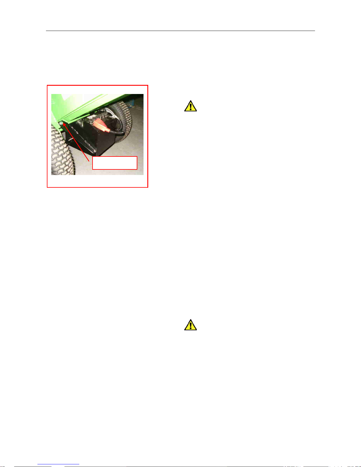
Fig 6.12 Battery (If fitted)
CAUTION! Do not steam clean
directly on to electrical components.
6.9 Tyres and Wheels
50 hours and 250 hours
6.9.1 Check condition of tyres.
6.9.2 Check pressures and inflate to 1.4bar
(20lb/in
2
) pressure as required.
Bolt each side
6.9.3 Check wheel nuts are tight.
6.10 Bearings and Pivots
weekly
See paragraph 6.1 for routine lubrication.
250 hours
6.10.1 Check rotating components for
excessive movement and noise in
operation.
6.10.2 Replace as required.
6.11 Mountings
250 hours
6.11.1 Check that all mounting bolts are
tight.
6.12 Battery (If fitted) (Fig 6.12)
First 50 hours and weekly
6.12.1 Check electrolyte level and top up if
required.
CAUTION! Gases are explosive.
Electrolyte is corrosive. Avoid sparks and
spillage.
6.12.2 Removal of battery
6.12.2.1 First disconnect negative (-) cable
(black cap).
6.12.2.2 Disconnect positive (+) cable (red
cap).
6.12.2.3 Remove bolts to allow tray to
drop and lift out battery.
6.12.2.4 Replace by connecting positive
cable before negative.
©GreenMechLtd 6-5 11/09
Page 18

GM C/S100 6. MAINTENANCE 6-6
6.12 Fault finding
Fault Check Action Page
Stop button Pull out to release
Engine stop switch push to I - start position 6-3
Fuel Fill tank - check tap on 6-3
Oil pressure Check Oil level 6-3
Engine will not start
Drive guard Fit to engage cut-out switch 6-3
Engine not at correct speed Engine throttle Check operation 5-1
Blockage Clear 5-1 Cutter not rotating
Drive belt tension Re-tension or replace 6-3
Discharge chute Check for blockage 5-1 Discharge does not flow
Cutter unit Check for blockage 5-1
Unusual noise(s) Bearings Check and replace 6-10
©GreenMechLtd 6-6 11/09
Page 19

CS 100 7. STORAGE 7-1
7.1 Storage
7.1.1 Thoroughly clean machine and note any replacement parts required.
7.1.2 Carry out 250 hour service if not already done. Refer to Section 6
7.1.3 Fit replacement parts when available.
7.1.4 Drain fuel
7.1.5 If machine is to be stored for more than 3 months, place on axle stands to remove
weight from wheels.
7.2 Removal from Storage
7.2.1 Check tyre pressures Refer to 6.9
7.2.2 Carry out machine preparation as necessary Refer to Section 4
©GreenMechLtd 7-1 06/09
Page 20

CS 100 8. DISPOSAL 8-1
When the machine is finally scrapped, the following items should be disposed of only at
authorised waste disposal facilities.
Engine oil. Tyres. Rubber components
If in doubt, consult the Local Authority environmental department.
©GreenMechLtd 8-1 06/09
Page 21

Safety Guides and Checklist as
Transcribed from and Advised by
Arborculture & Forestry Advisory Group
and Issued as Leaflet 604 by HSE, issued
04/03
INTRODUCTION
This leaflet covers the safe working practices
to be followed when operating a wood
chipper.
It does not cover a combination of machines
working within each other’s risk zones (see
AFAG leaflet 605 Mechanical roadside
processing)
You can use this leaflet, along with the
manufacturer’s handbook, as part of the risk
assessment process to help identify the
controls to put in place when using a wood
chipper.
You must also assess the effect of the site and
the weather as well as following this guidance
All operators must have had appropriate
training in how to operate the machine and
how to carry out the tasks require (see AFAG
leaflet 805 Training and certification)
PERSONAL PROTECTIVE
EQUIPMENT (PPE)
1. Use the following PPE
•
•
•
•
•
•
A Safety Helmet, complying with EN
397, if identified as required in the risk
assessment.
Eye Protection (a mesh visor complying
with EN1731 or safety glasses to EN166)
Hearing protection (complying with
EN352) where noise level exceeds 85
dB(A) (see HSE pocket card INDG363
Protect your hearing or lose it!)
Gloves.
Safety Boots with good grip and ankle
support (complying with EN345-1)
Non-Snag Outer Clothing appropriate to
prevailing weather conditions. Highvisibility clothing (complying with
EN471) should be worn when the risk
assessment identifies that it is needed.
2. Each person should carry a personal first-
aid kit including a large wound dressing
(see HSE leaflet INDG214 first aid at
work; Your questions answered).
3. Hand cleaning material such as waterless
skin cleanser or soap, water and paper
towel should be readily available.
THE MACHINE
4. Before working with a machine, check it
has been properly converted from any
transport mode.
5. Ensure guards for dangerous parts (e.g.
belts, pulleys, shafts etc) are secure and
undamaged.
6. Ensure protective devices, such as the
infeed control bar (incorporating the
stopping device), are working correctly
(see HSE leaflet AI S 38 Power-fed
mobile wood chippers: Operator
protection at infeed chutes).
7. Ensure any lock for the chipping
components has been disengaged;
8. Ensure the infeed hopper is clear of any
materials.
9. Ensure Noise warning signs are in place.
10. For machines driven by a power take-off
(PTO) shaft, before starting ensure:
Page 1
Page 22

•
•
•
The PTO shaft is fitted with a suitable
guard complying with EN1152, that
encloses the shaft along its full length
from tractor to machine.
The guard is correctly fitted and in
effective working order (see AS24(rev)
Power take-offs and power take-off drive
shafts);
The PTO speed is suitable for the
machine.
SELECTING THE WORK AREA
11. Select as firm a surface as possible and
stabilise the machine
12. Ensure ventilation is adequate and any
exhaust fumes are vented into open air if
working in an enclosed space.
13. Where appropriate, if the chipper is
detached from the tow vehicle, apply the
handbrake and, if necessary, chock the
wheels.
14. On all reasonably foreseeable approaches
to the worksite, erect warning and
prohibition signs conforming to the Health
and Safety (Safety Signs and Signals)
Regulations 1996, indicating a hazardous
worksite and that unauthorised access is
prohibited. In areas of very high public
access, a risk assessment may indicate that
additional controls (e.g. barrier tape,
barriers, extra manning) are required.
15. Ensure all operations near to highways are
adequately signed with the appropriate
notices as specified in the DTLR Code of
Practice Safety at street works and road
works (available from The Stationary
Office ISBN 0 11 551958 -0)
16. Ensure that the discharge chute is
positioned to prevent chips being blown
onto the highway during roadside
operations, or in any direction where they
can affect colleagues or members of the
public.
17. Position the chipper so that operators do
not have to stand on embankments/slopes
when feeding material into the machine
EMERGENCY PROCEDURES
18. Ensure a designated and responsible
person knows the daily work programme
and agree with them a suitable emergency
contact procedure. Where reasonably
practicable use a mobile phone or radio
and pre-arrange call-in system.
19. Ensure the operators can provide the
emergency services with enough detail for
them to be found in the event of an
accident, e.g. the grid reference, the
distance from the main road, the type of
access (suitable for car/four-wheel
drive/emergency service vehicles). In
urban areas street names are essential.
Know the location details before they are
needed in an emergency. (Also see AFAG
leaflet 802 Emergency planning)
OPERATION
20. Make sure the cuffs of gloves are close
fitting or tucked into you’re sleeves to
stop them being caught on material as it is
fed into the chipper.
21. Set the engine speed (and set the stress
control if fitted) to obtain optimum
performance.
22. Check that material to be chipped is free
from stones, metal and foreign objects.
23.
Stand to one side of the infeed rollers to
avoid being hit by ejected material.
24. Let material go as soon as it is engaged in
the infeed rollers or chipping components.
Page 2
Page 23

25. Use a push stick at least 1.5 metre long,
for both short produce and for the last
piece of produce to be chipped.
26. Do not put any part of your body
(including hands or feet), into the infeed
hopper while the machine is running.
27. Always follow the manufactures’
instructions for dealing with blockages on
the machine.
28. Keep the area of ground in front of the
infeed hopper free from debris to prevent
any tripping hazard.
29. Remove the engine start key when the
machine is left unattended or when
undertaking any maintenance.
FUELLING
30. Stop engine and, if necessary allow the
machine to cool before refuelling.
31. Petrol vapour is invisible and can flow
considerable distances from spillage or
fuelling sites. Maintain a safe distance
from any source of ignition at all times.
32. Store fuel to avoid vapour ignition from
any source such as fires, people smoking
or the wood chipper. Select a site shaded
from direct sunlight and away from
watercourses and drains.
33. Containers must be clearly labelled and
have securely fitting caps. Plastic
containers must be designed and approved
for use with petrol or diesel fuel.
34. Replace the fuel cap securely.
35. Keep fuel from contacting the skin. If
fuel gets into the eyes wash out with
sterile water immediately and seek
medical advise
Maintenance
36. Ensure the machine is carried out in
accordance with the manufacture’s
handbook.
37. Check chipping components and knives
each day for damage and wear.
38. Wear gloves when handling knives.
39. Before working on knives, confirm that
the engine is switched off, the start key
removed, and the chipping component is
stationary.
40. Before opening any guard/cover or
reaching into the infeed hopper or
discharge chutes make sure that the engine
is switched off, start key removed and
dangerous parts have come to a stand still.
41. Knives must be changed or reversed if
damaged or blunt. Knives must be
scrapped when worn to the minimum size
specified by the manufacturer.
42. When new/sharpened knives are fitted,
ensure that there is the recommended
clearance between the knives and the
anvil.
MOVING THE MACHINE
43. Stop the engine and remove the start/stop
key.
44. Lock the chipping components.
45.
Secure the infeed hopper and the chip
discharge chute in the transport position.
46. Check the towing bracket, attach, then lift
and secure the jockey wheel.
47. Connect the electrics and the safety
chain/s to the towing vehicle.
Page 3
Page 24

48. Ensure that the load is secure and that
people are in a safe position before
moving off.
For further leaflets and reading see HSE web
site:
www.hse.gov.uk
Further HSE Reading
Mechanical roadside processing AFAG605
Emergency planning AFAG802
Training and certification AFAG805
First aid at work:
Your questions answered INDG214
Managing health and safety
In forestry INDG294
Protect your hearing or lose it! INDG363
Further reading Continued
Power-fed mobile wood chippers:
Operator protection at infeed chute AIS38
Power take-offs and power take-off
drive shafts AS24
Page 4
Page 25
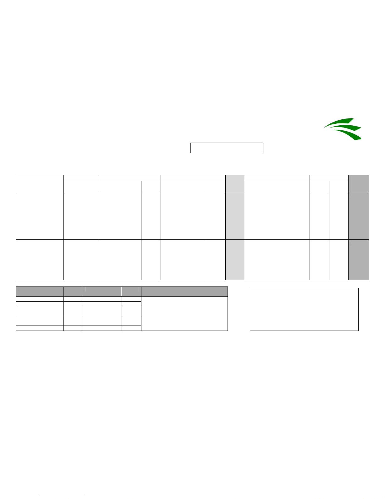
Risk Assessment
Company Name: GreenMech Ltd Activity: CS 100
At Risk Consequence ( C) Likelihood (L) Controls Revised Hazard
Those likely
to be affected
Likely injury
from hazard
Rating
Of incident
Rating
Risk
Score
C
L
Rating Rating
Final
Risk
Score
ENTANGLEMENT
With cutter in base
of CHIPPER
infeed chute
OPERATOR FATALITY –
LOSS OF LIMB
5 VERY LIKELY 5 25 Reach area safety
distance to cutter complies
to latest HSE guidelines.
Emergency stop button is
within easy reach of
operator. Only appointed
operators to use machine
(competent)
5 2
10
STABBING AND
PUNCTURE by
projectiles from
cutter. Wood,
stones, nails
rebound back out
of infeed chute
OPERATOR Injuries to face,
eyes, head and
hands
3 PROBABLE 4
12 Trained Operator. Check
only green waste is fed
into machine.
Safety helmet to BSEN
397
Forestry visor
Hard wearing gloves
3 2
6
Key:
Consequence Score Likelihood Score To find risk Score multiply consequence
rating by the likelihood rating
Fatality 5 Very likely 5
Disability 4 Probable 4
Very serious (broken
limbs)
3 Possible 3
Important (3 day
accident)
2 Remotely possible 2
Noticeable (first aid) 1 Improbable 1
Final revised risk score acceptable to the
company is 10 or less. If higher, further
controls are required.
Final revised likelihood score must be 2 or
less
Signed: ……………………………
Date: …………………………….
Review Date: …………………………….
Assessment No: G001
GreenMech Ltd
A Turner Company
Page 26
GreenMech Ltd
A Turner Company
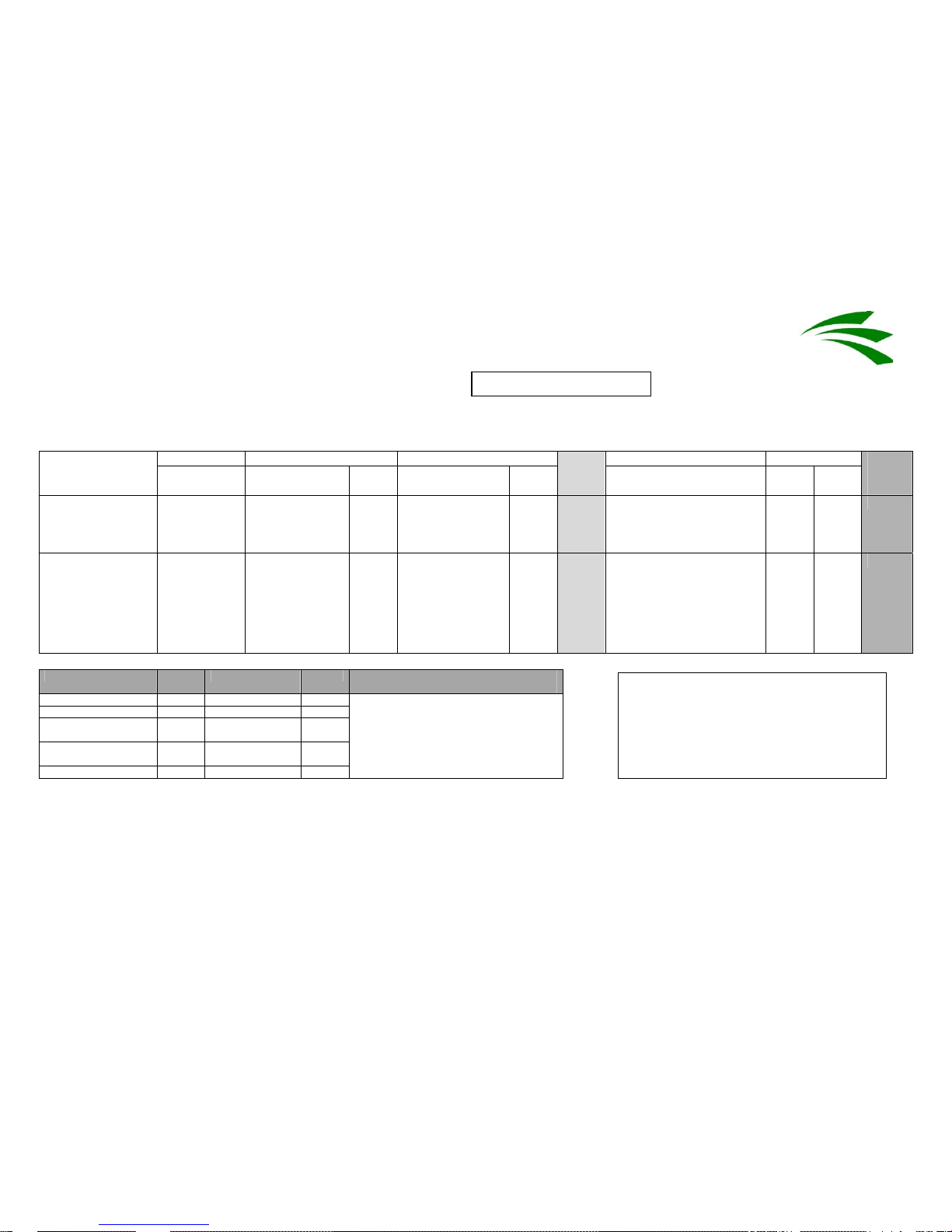
Risk Assessment
Assessment No: G001-2
Company Name: GreenMech Ltd Activity: CS 100
At Risk Consequence ( C) Likelihood (L) Controls Revised Hazard
Those likely
to be affected
Likely injury
from hazard
Rating
Of incident
Rating
Risk
Score
C
L
Rating Rating
Final
Risk
Score
NOISE
Guaranteed sound
pressure level of
Lwa 100dB
OPERATOR
THIRD
PARTY
NOISE
INDUCED
HEARING
LOSS
4 PROBABLE 4 16 Wear hearing protection to
BE EN 352-3.
Display mandatory ‘wear
hearing protection’ sign
4 2 8
VIBRATION –
movement of
machine
OPERATOR BROKEN OR
BRUISED LIMB
3 POSSIBLE 3 9 Trained Operator.
Lock off handbrake
Chock wheels and secure
stabiliser in place
Stand machine on sound
level ground
3 2
6
Key:
Consequence Score Likelihood Score To find risk Score multiply consequence
rating by the likelihood rating
Fatality 5 Very likely 5
Disability 4 Probable 4
Very serious (broken
limbs)
3 Possible 3
Important (3 day
accident)
2 Remotely possible 2
Noticeable (first aid) 1 Improbable 1
Final revised risk score acceptable to the
company is 10 or less. If higher, further
controls are required.
Final revised likelihood score must be 2 or
less
Signed: ……………………………
Date: …………………………….
Review Date: …………………………….
Page 27
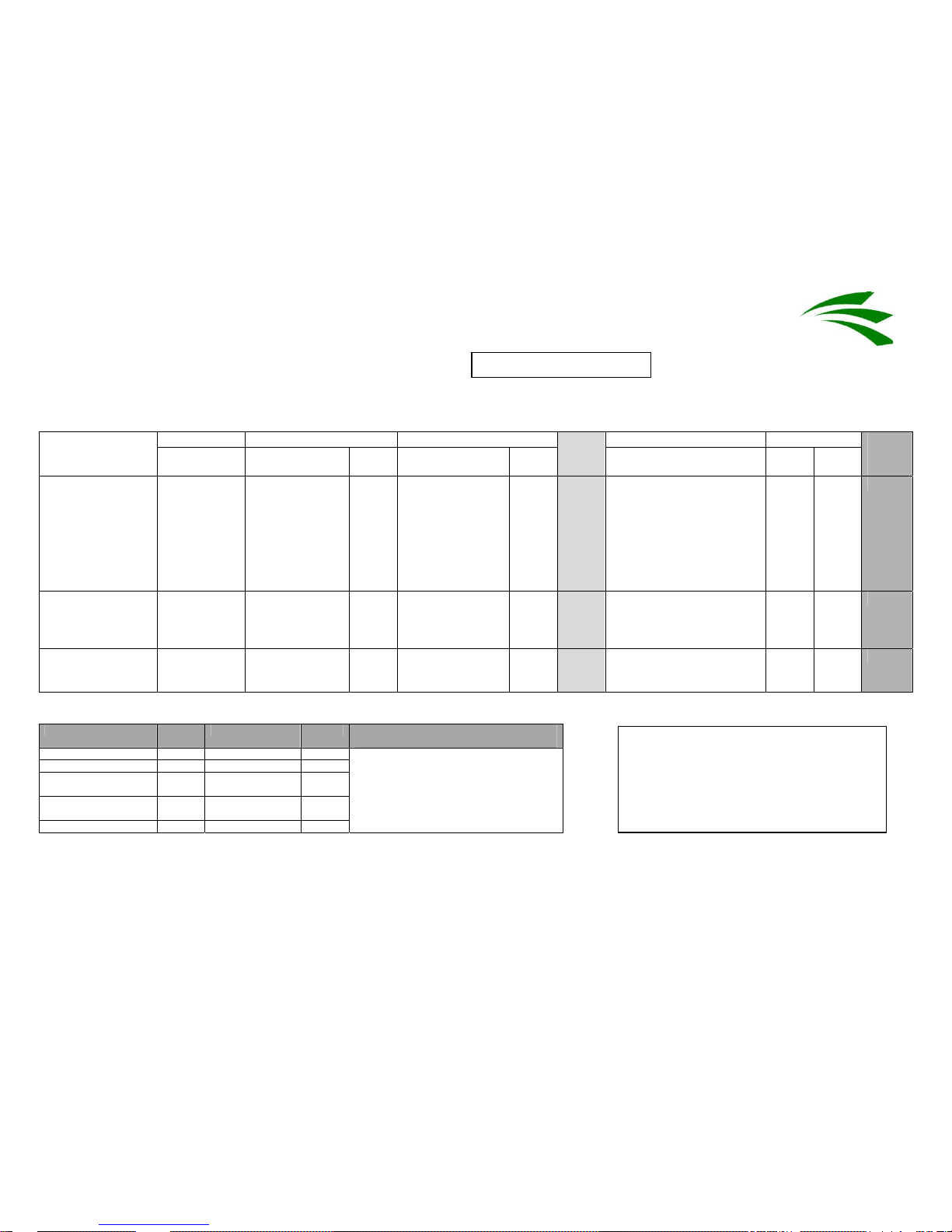
GreenMech Ltd
A Turner Company
Risk Assessment
Assessment No: G001-3
Company Name: GreenMech Ltd Activity: CS 100
At Risk Consequence ( C) Likelihood (L) Controls Revised Hazard
Those likely
to be affected
Likely injury
from hazard
Rating
Of incident
Rating
Risk
Score
C
L
Rating Rating
Final
Risk
Score
ENTANGLEMENT
Branches with
clothing
OPERATOR Drawn into
cutters –
FATALITY –
LOSS OF
LIMBS
5 POSSIBLE 3
15 Wear snug fitting clothes.
No ties, scarves etc.
Same controls as for
previous hazard of
entanglement with cutters.
Wear gloves with long
cuffs which can be tucked
into sleeves
5 2
10
STABBING AND
PUNCTURE –
Processed green
waste
OPERATOR
THIRD
PARTY
EYE INJURIES,
CUTS TO FACE
1 POSSIBLE 3
3 Trained operator
Cordon off collection point
Cordon off discharge area
1 1 2
STABBING AND
PUNCTURE –
Handling branches
OPERATOR CUTS TO
HANDS
2 QUITE
POSSIBLE
4 8 Wear hard wearing gloves
with long cuffs that can be
tucked into sleeves.
2 2 4
Key:
Consequence Score Likelihood Score To find risk Score multiply consequence
rating by the likelihood rating
Fatality 5 Very likely 5
Disability 4 Probable 4
Very serious (broken
limbs)
3 Possible 3
Important (3 day
accident)
2 Remotely possible 2
Noticeable (first aid) 1 Improbable 1
Final revised risk score acceptable to the
company is 10 or less. If higher, further
controls are required.
Final revised likelihood score must be 2 or
less
Signed: ……………………………
Date: …………………………….
Review Date: …………………………….
Page 28
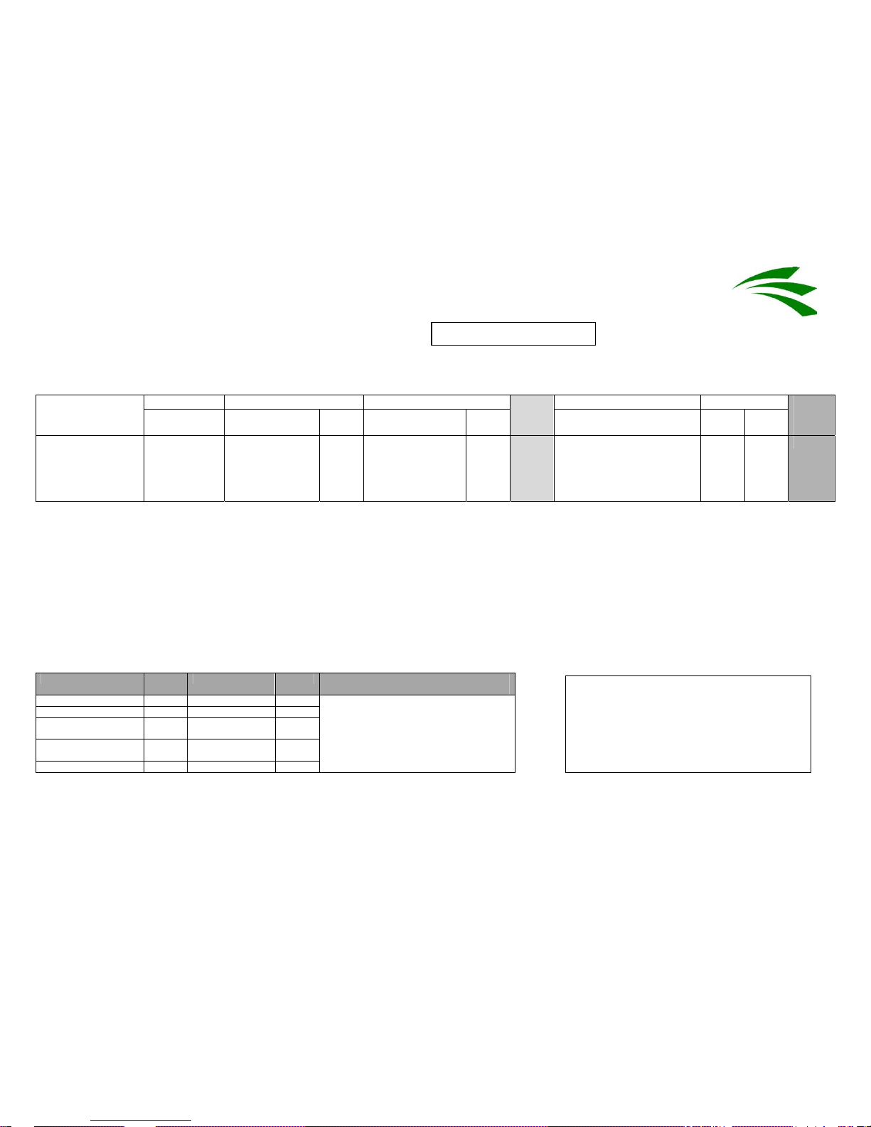
GreenMech Ltd
A Turner Company
Risk Assessment
Assessment No: G001-4
Company Name: GreenMech Ltd Activity: CS 100
At Risk Consequence ( C) Likelihood (L) Controls Revised Hazard
Those likely
to be affected
Likely injury
from hazard
Rating
Of incident
Rating
Risk
Score
C
L
Rating Rating
Final
Risk
Score
IMPACT
Being struck by
branch when
feeding green
waste into cutters
OPERATOR BROKEN LIMB
BRUISES
3 POSSIBLE 3
9 Stand at side of machine.
Trained operator
3 2 6
Key:
Consequence Score Likelihood Score To find risk Score multiply consequence
rating by the likelihood rating
Fatality 5 Very likely 5
Disability 4 Probable 4
Very serious (broken
limbs)
3 Possible 3
Important (3 day
accident)
2 Remotely possible 2
Noticeable (first aid) 1 Improbable 1
Final revised risk score acceptable to the
company is 10 or less. If higher, further
controls are required.
Final revised likelihood score must be 2 or
less
Signed: ……………………………
Date: …………………………….
Review Date: …………………………….
Page 29
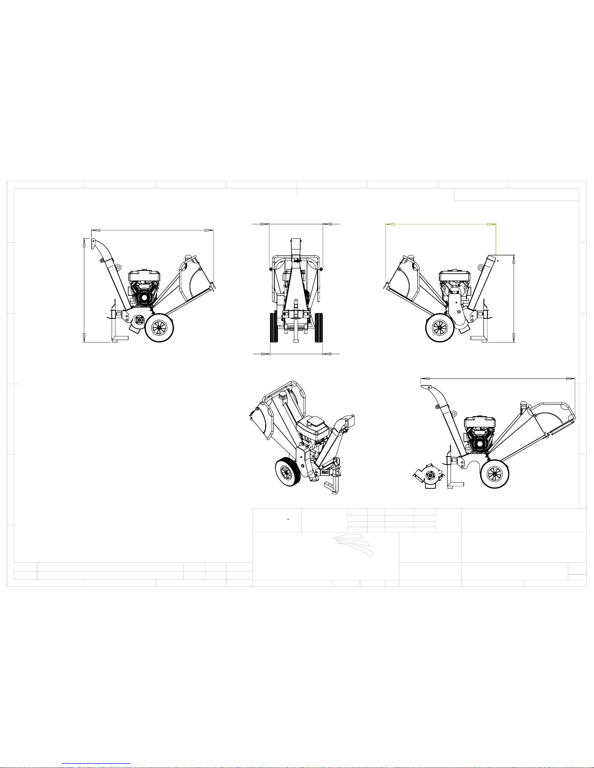
741
mm
760
mm
1468
mm
1725
mm
1234
mm
1560
mm
2182
mm IN OPERATION
CASSETTE REMOVED
CS100 SPECIFICATIONS:
ENGINE: 14HP or 18HP 4-STROKE VANGUARD V-TWIN OHV
EMPTY WEIGHT- CS100-14HP: 195Kg, CS100-18HP: 197Kg
DIMENSIONS (HxLxW): 1468 x 1725 x 760mm
GUARANTEED WOOD DIAMETER: 80mm
PERMITTED WOOD DIAMETER: 130mm
PETROL CONSUMPTION (WITH CONTINUOUS CHIPPING): 2.8 L/HOUR
D
E
F
C
1
2
3
B
A
3
2
1
5
C
D
4
6
7
8
A
B
CS100
CS100
WEIGHT:
A3
SHEET 3 OF 3
SCALE:1:20
DWG NO.
TITLE:
TOLERANCES
MATERIAL:
DATE
SIGNATURE
NAME
DEBUR AND
BREAK SHARP
EDGES
FINISH:
TOLERANCES:
LINEAR: 0.025MM
ANGULAR: 0.25
APPV'D
CHK'D
DRAWN
SDS
SDS
28.05.09
REV
MODIFICATION
DRN
APPD
DATE
GreenMech Ltd
The Mill Industrial Park
Kings Coughton
Alcester
Warks B49 5QG Tel 01789 400044
PROGRAM No:-
DIMNS IN MM
1ST ANGLE PROJECTION
DO NOT SCALE - IF IN DOUBT ASK
MACHINED PARTS +/- 0.025mm
FABRICATED PARTS +/-1.0mm
Page 30
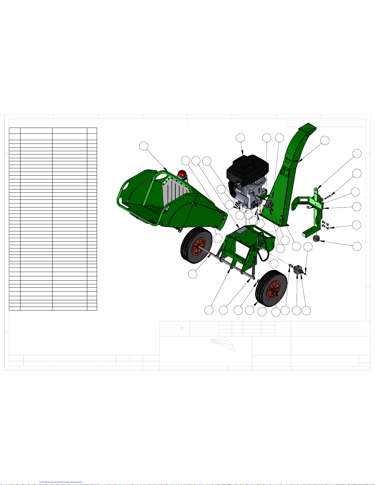
1
12
39
37
6
5
9
38
13
46
332
2
45
11
15
31
21
26
167
23
27 42
20
19
50
17
18
8
37
32
33
27
52
53
ITEM
NO.
PART NUMBER
DESCRIPTION
QTY
1
CS100-6-1001 14HP
CS100-6-1002 18HP
V-TWIN ENGINE
1
2
CS100-1
CHASSIS FAB
1
3
CS100-1-10
WHEEL
2
4
CS100-1-11
BELT COVER FAB
1
5
CS100-1-18
MOUNT PLATE
1
6
CS100-1-20
MOUNT PIN
1
7
CS100-1-27
COVER MOUNT
1
8
CS100-1-7
WHEEL AXLE
1
9
CS100-1-9
DRAW BAR FAB
1
10
CS100-2
CASSETTE ASSEMBLY
2
11
CS100-4
INFEED ASSEMBLY
1
12
CS100-5
DISCHARGE CHUTE
1
13
CS100-6-4
IDLER BUSH
1
14
910100EB
M10 x 100 EYE BOLT
1
15
CS100-6-7
ROLLER BEARING
2
16
903825UNC
3/8 UNC x 25mm
2
17 90502
M5 WASHER
4
18
90535BH
M5 x 35mm B/HEAD
2
19 90802
M8 WASHER
7
20 90803
M8 spring washer
7
21 90845
M8 x 45mm
4
22
91001=P
M10 plain nut
4
23
91001-NYLOC
M10 NYLOC NUT
11
24 91002
M10 B WASHER
27
25 91003
M10 S/WASHER
15
26 91030
M10 x 30mm
2
27 91030
M10 x 30mm
10
28 91080
M10 x 80mm
1
29 91202
M12 flat washer
4
30 91203
M12 spring washer
4
31 91225
M12 x 25mm
4
32 92002
M20 WASHER
4
33
CS100-6-8
BELT
2
34
C200216
GLAND
2
35
Conduit Conduit
1
36
Conduit2
Conduit
1
37
EC150021-1
LYNCH PIN
3
38
CS100-6-9
BUMP STOP
1
39
CS100-6-15
PULLEY
1
40 90825
M8 UNPLATED BOLT
1
41
M8 Grip nut
1
42
SN Plate
1
45
CS100-1-8
AXLE TUBE
2
46
CS100-6-19
TENSIONER PULLEY
1
49
CS100-6-20
WASHER
1
50
90501-NYLOC
M5 NYLOC NUT
2
51 9051619
516 UNF
2
52
C200206
MICROSWITCH
1
53
CS100-6-11
TL BUSH
1
D
E
F
C
1
2
3
B
A
3
2
1
5
C
D
4
6
7
8
A
B
CS100
CS100
WEIGHT:
A3
SHEET 1 OF 3
SCALE:1:10
DWG NO.
TITLE:
TOLERANCES
MATERIAL:
DATE
SIGNATURE
NAME
DEBUR AND
BREAK SHARP
EDGES
FINISH:
TOLERANCES:
LINEAR: 0.025MM
ANGULAR: 0.25
APPV'D
CHK'D
DRAWN
SDS
SDS
28.05.09
REV
MODIFICATION
DRN
APPD
DATE
GreenMech Ltd
The Mill Industrial Park
Kings Coughton
Alcester
Warks B49 5QG Tel 01789 400044
PROGRAM No:-
DIMNS IN MM
1ST ANGLE PROJECTION
DO NOT SCALE - IF IN DOUBT ASK
MACHINED PARTS +/- 0.025mm
FABRICATED PARTS +/-1.0mm
Page 31

33
4
41
10
27
22
40
20
19
14
24 2528
24
51
52
D
E
F
C
1
2
3
B
A
3
2
1
5
C
D
4
6
7
8
A
B
CS100
CS100
WEIGHT:
A3
SHEET 2 OF 3
SCALE:1:10
DWG NO.
TITLE:
TOLERANCES
MATERIAL:
DATE
SIGNATURE
NAME
DEBUR AND
BREAK SHARP
EDGES
FINISH:
TOLERANCES:
LINEAR: 0.025MM
ANGULAR: 0.25
APPV'D
CHK'D
DRAWN
SDS
SDS
28.05.09
REV
MODIFICATION
DRN
APPD
DATE
GreenMech Ltd
The Mill Industrial Park
Kings Coughton
Alcester
Warks B49 5QG Tel 01789 400044
PROGRAM No:-
DIMNS IN MM
1ST ANGLE PROJECTION
DO NOT SCALE - IF IN DOUBT ASK
MACHINED PARTS +/- 0.025mm
FABRICATED PARTS +/-1.0mm
Page 32
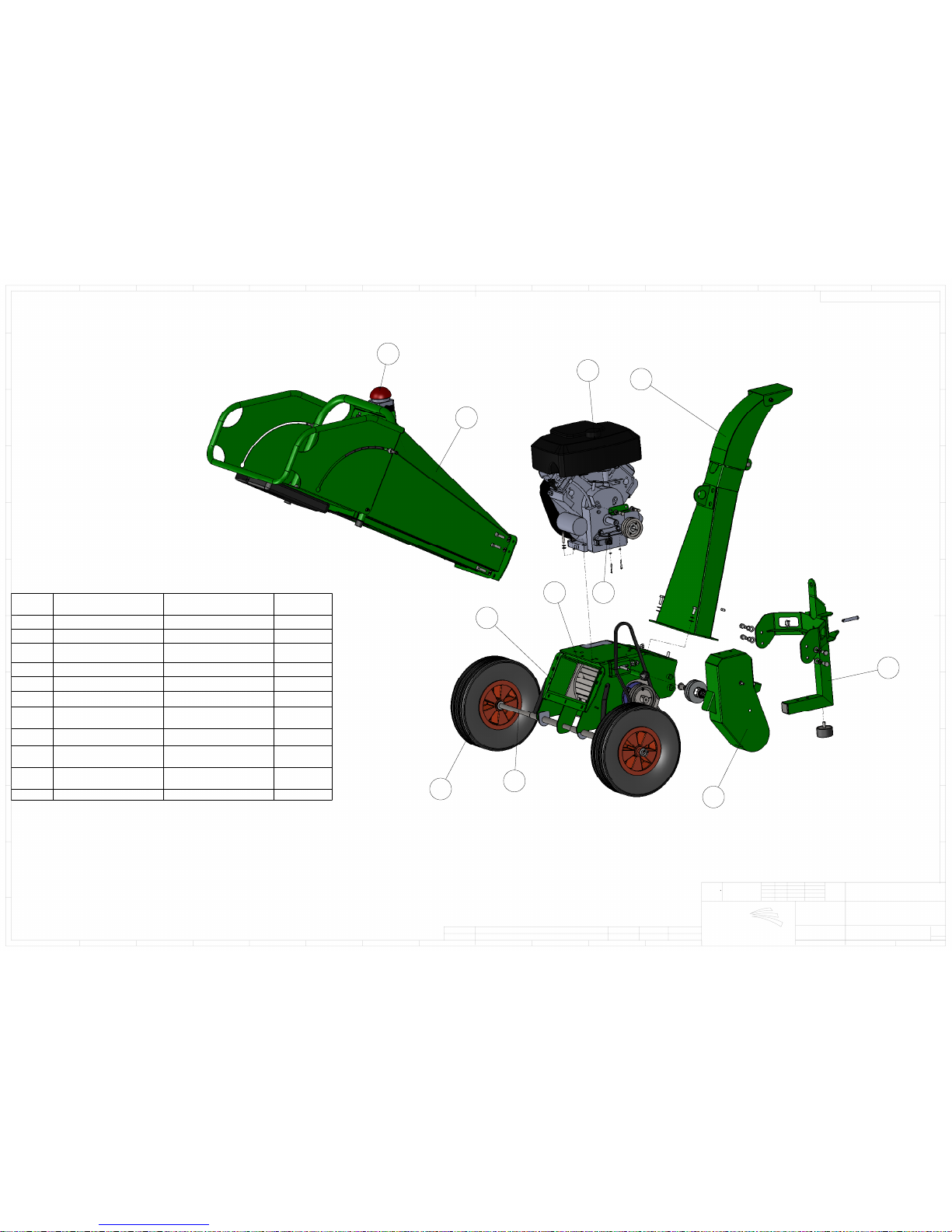
2
9
10
8
6
5
1
3
4
7
11
ITEM
NO.
PART NUMBER
DESCRIPTION
QTY
1
CS100-1
CHASSIS FAB
1
2
CS100-4
INFEED ASSEMBLY
1
3
CS100-2
CASSETTE ASSEMBLY
1
4
CS100-5
DISCHARGE CHUTE
1
5
CS100-1-10
WHEEL
2
6
CS100-1-7
WHEEL AXLE
1
7
CS100-6-23
EMERGENCY
STOP
1
8
CS100-1-11
BELT GUARD
1
9
CS100-6-100114 HP
CS100-6-1002 18HP
V-TWIN ENGINE
1
10
CS100-1-9
DRAWBAR
ASSEMBLY
1
11
C200206
MICROSWITCH
1
F
8
E
D
C
B
A
G
H
J
K
L
M
7
6
5
4
3
2
1
9
10
11
12
13
14
15
16
9
1
2
3
4
5
6
7
8
10
11
12
K
G
A
B
C
D
E
F
H
J
CS100
CS100 MAIN
WEIGHT:
A1
SHEET 1 OF 1
SCALE:1:20
DWG NO.
TITLE:
TOLERANCES
MATERIAL:
DATE
SIGNATURE
NAME
DEBUR AND
BREAK SHARP
EDGES
FINISH: xxxxxxxxxxx
TOLERANCES:
LINEAR: 0.025mm
ANGULAR: 0.25
APPV'D
CHK'D
DRAWN
BGG
XXXXXXXX
BGG
GreenMech Ltd
The Mill Industrial Park
Kings Coughton
Alcester
Warks B49 5QG Tel 01789 400044
REV
MODIFICATION
DRAWN
APPRD
DATE
PROGRAM No:-
1ST ANGLE PROJECTION
DIMNS IN MM
DO NOT SCALE - IF IN DOUBT ASK
MACHINED PARTS +/- 0.025mm
FABRICATED PARTS +/- 1.0mm
Page 33
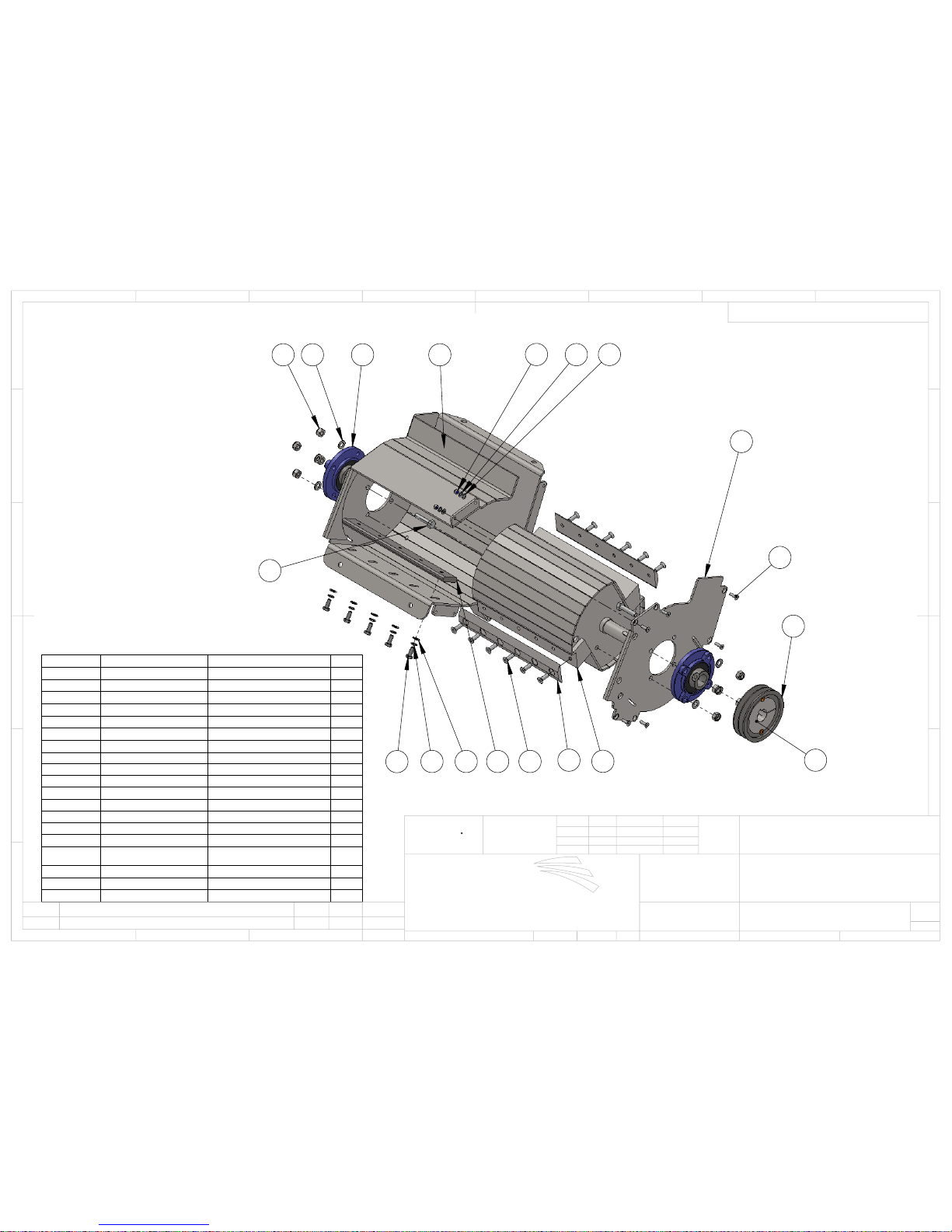
3
9
16
4
5
7
8
6
1
2
121011
18
15 13 17
14
19
ITEM NO.
PART NUMBER
DESCRIPTION
QTY.
1
CS100-2-1
CHIPPER DRUM
1
2
CS100-2-6
CHIPPER BLADE
2
3
CS100-2-12
SHEAR BAR
1
4
CS100-2-14
DRIVESIDE FAB
1
5
CS100-2-15
CASSETTE FAB
1
6
90601-Nyloc
M6 Nyloc nut
6
7 90602
M6 flat washer
6
8 90603
M6 S/WASHER
6
9
90620CS
M6 x 20mm C/SUNK
6
10 90802
M8 flat washer
5
11 90803
M8 spring washer
5
12
90825CS
M8 x 25mm C/SUNK
12
13 91002
M10 B WASHER
8
14 91040
M10 x40mm BOLT
8
15
91001-NYLOC
M10 NYLOC NUT
8
16
CS100-6-12
PULLEY
1
17
C180109-1
MFC30
2
18 90820
M8 x 20mm
5
19
CS100-6-13
TL BUSH
D
E
F
C
1
2
3
B
A
3
2
1
5
C
D
4
6
7
8
A
B
CASSETTE ASSEMBLY
CS100-2
WEIGHT:
A3
SHEET 1 OF 1
SCALE:1:5
DWG NO.
TITLE:
TOLERANCES
MATERIAL:
DATE
SIGNATURE
NAME
DEBUR AND
BREAK SHARP
EDGES
FINISH:
TOLERANCES:
LINEAR: 0.025MM
ANGULAR: 0.25
APPV'D
CHK'D
DRAWN
SDS
SDS
10.03.2009
REV
MODIFICATION
DRN
APPD
DATE
GreenMech Ltd
The Mill Industrial Park
Kings Coughton
Alcester
Warks B49 5QG Tel 01789 400044
PROGRAM No:-
DIMNS IN MM
1ST ANGLE PROJECTION
DO NOT SCALE - IF IN DOUBT ASK
MACHINED PARTS +/- 0.025mm
FABRICATED PARTS +/-1.0mm
Page 34
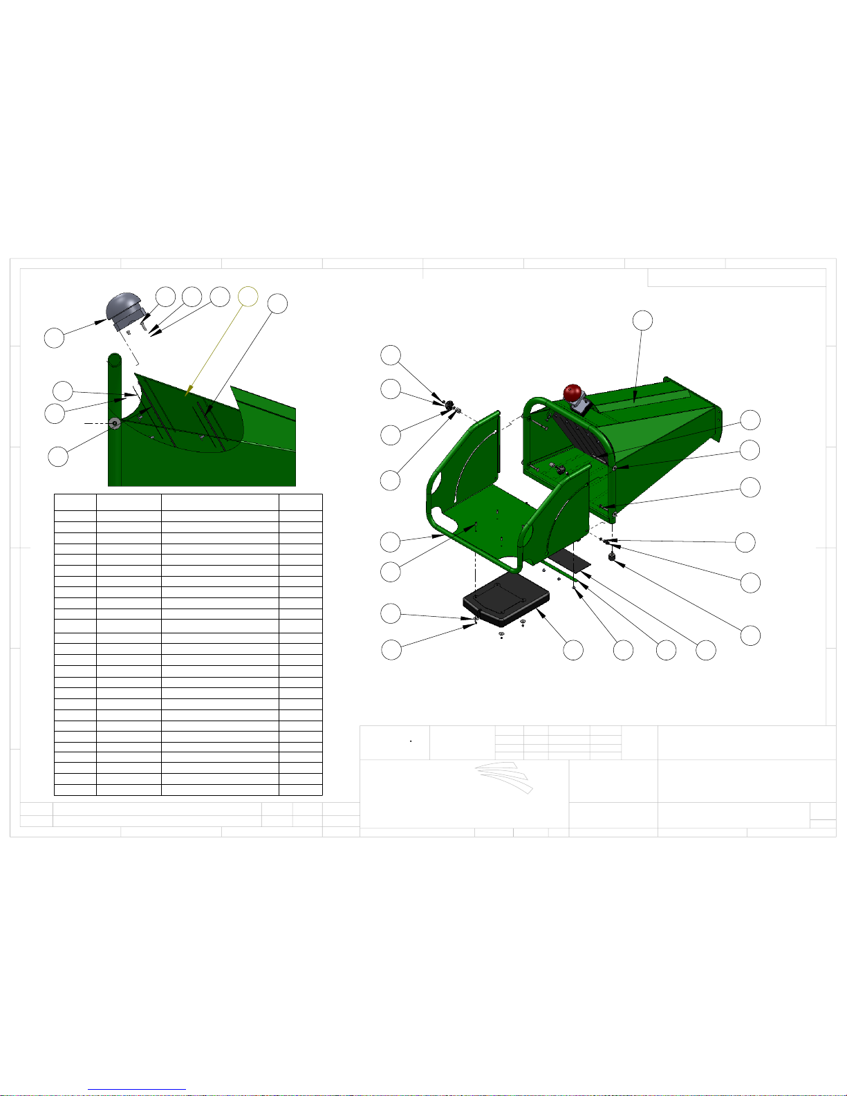
1
25
2
3
22
6
20
20
22
23
7
81113
12
17
16
14
24
10
?
5
4
11
151819
26
ITEM NO.
PART NUMBER
DESCRIPTION
QTY
1
CS100-4-1
INFEED CHUTE FAB
1
2
CS100-4-8
INFEED FLAP FAB
1
3
CS100-4-14
NYLON SPACER
2
4
CS100-4-15
UPPER CURTAIN STRIP
1
5
CS100-4-16
CURTAIN
1
6
CS100-4-17
M8 THUMBNUT (F)
2
7
CS100-4-19
Rubber Guard
1
8
CS100-4-20
RETAINING STRIP
1
9
CS100-4-24
LOWER CURTAIN STRIP
1
10
CS100-4-25
LOWER CURTAIN
1
11
R51216
RIVET 4.8 x 12mm
24
12
CS100-6-14
BUMPSTOP
2
13
9000-08
DOCUMENT CASE
1
14
90501-Nyloc
M5 NYLOC NUT
4
15 90502
M5 WASHER
2
16
90502-R
M5 x 25mm WASHER
4
17
90516BH
M5 x 16mm B/HEAD
4
18 90503
M5 S/WASHER
2
19
90525BH
M5 x 25mm B/HEAD
2
20
90801-Nyloc
M8 Nyloc nut
4
22 90802
M8 flat washer
4
22
908100CB
M8 x 100mm CARRIAGE
2
23
90855CB
M8 x 55mm CARRIAGE
2
24
CS100-6-15
M8 NUT CAP
2
25
91005-NYLON
M10 NYLON WASHER
4
26
CS100-6-23
KILL SWITCH
1
D
E
F
C
1
2
3
B
A
3
2
1
5
C
D
4
6
7
8
A
B
INFEED ASSEMBLY
CS100-4
WEIGHT:
A3
SHEET 1 OF 1
SCALE:1:10
DWG NO.
TITLE:
TOLERANCES
MATERIAL:
DATE
SIGNATURE
NAME
DEBUR AND
BREAK SHARP
EDGES
FINISH:
TOLERANCES:
LINEAR: 0.025MM
ANGULAR: 0.25
APPV'D
CHK'D
DRAWN
SDS
SDS
16.03.2009
REV
MODIFICATION
DRN
APPD
DATE
GreenMech Ltd
The Mill Industrial Park
Kings Coughton
Alcester
Warks B49 5QG Tel 01789 400044
PROGRAM No:-
DIMNS IN MM
1ST ANGLE PROJECTION
DO NOT SCALE - IF IN DOUBT ASK
MACHINED PARTS +/- 0.025mm
FABRICATED PARTS +/-1.0mm
Page 35
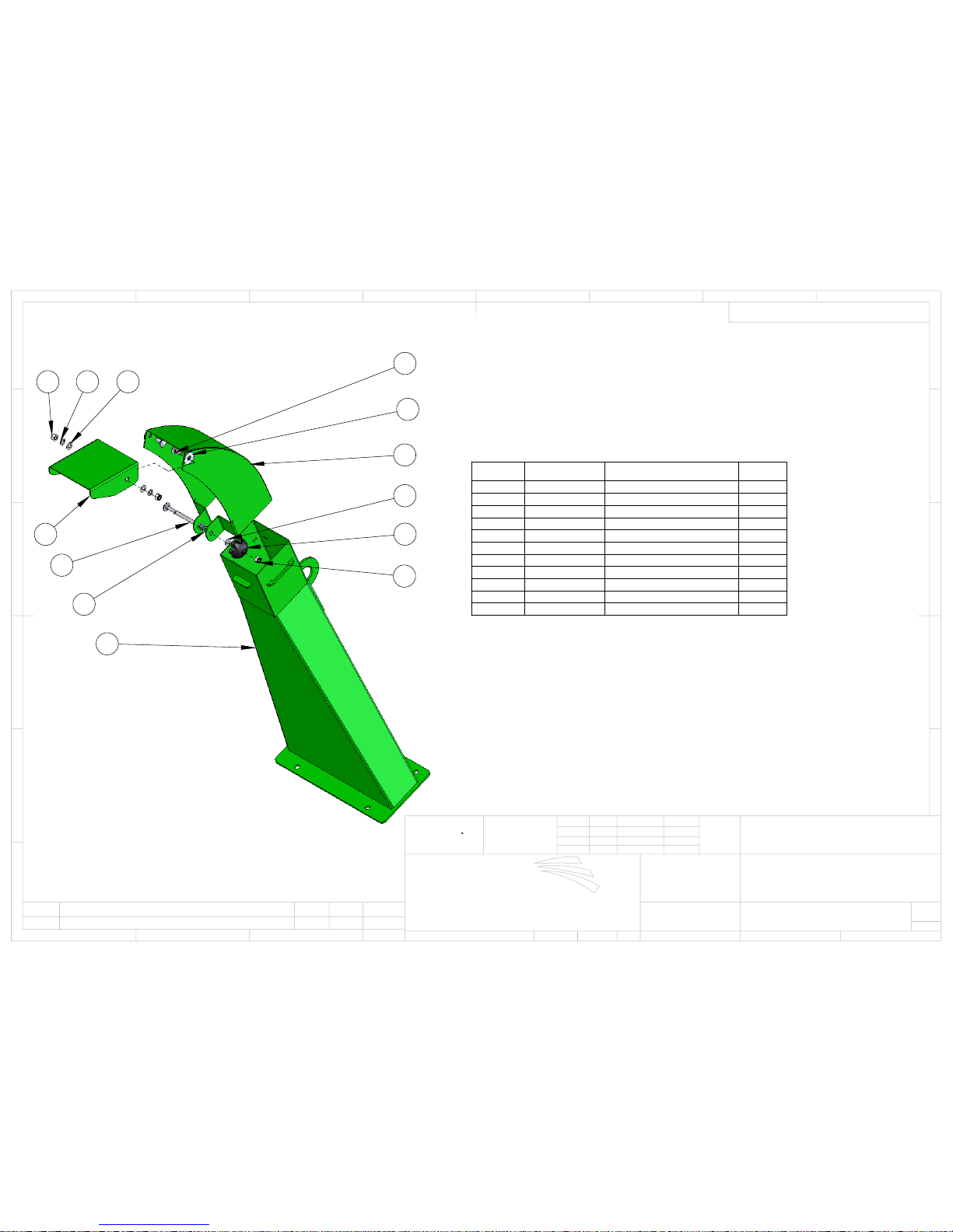
10
2
5
9
4
1
8
3
7
4 6 5
11
ITEM NO.
PART NUMBER
DESCRIPTION
Default/
QTY.
1
CS100-5-10
DISCHARGE FAB
1
2
CS100-5-5
DISCHARGE END
1
3
CS100-5-7
DISCHARGE FLAP
1
4
90801-Nyloc
M8 Nyloc nut
3
5 90802
M8 flat washer
3
6 90803
M8 spring washer
2
7
90820CB
M8 x 20mm CARRIAGE
2
8
908100CB
M8 x 100mm CARRIAGE
1
9
CS100-4-17
M8 THUMBNUT (F)
1
10
91005-NYLON
M10 NYLON WASHER
2
11
EC1523-432
SPRING
1
D
E
F
C
1
2
3
B
A
3
2
1
5
C
D
4
6
7
8
A
B
DISCHARGE CHUTE
CS100-5
WEIGHT:
A3
SHEET 1 OF 1
SCALE:1:5
DWG NO.
TITLE:
TOLERANCES
MATERIAL:
DATE
SIGNATURE
NAME
DEBUR AND
BREAK SHARP
EDGES
FINISH:
TOLERANCES:
LINEAR: 0.025MM
ANGULAR: 0.25
APPV'D
CHK'D
DRAWN
SDS
SDS
17.03.2009
REV
MODIFICATION
DRN
APPD
DATE
GreenMech Ltd
The Mill Industrial Park
Kings Coughton
Alcester
Warks B49 5QG Tel 01789 400044
PROGRAM No:-
DIMNS IN MM
1ST ANGLE PROJECTION
DO NOT SCALE - IF IN DOUBT ASK
MACHINED PARTS +/- 0.025mm
FABRICATED PARTS +/-1.0mm
Page 36
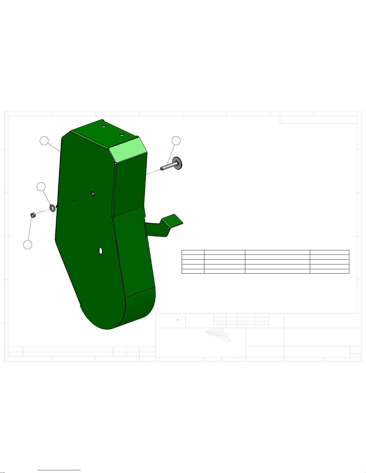
1
3
4
2
ITEM NO.
PART NUMBER
DESCRIPTION
fab/QTY.
1
CS100-1-11
BELT COVER
1
2
EC130-1-105
M/SWITCH STRIKER
1
3 90803
FLAT WASHER
1
4
90801 P
PLAIN NUT
1
D
E
F
C
1
2
3
B
A
3
2
1
5
C
D
4
6
7
8
A
B
BELT GUARD
CS100-1-11EX
WEIGHT:
A3
SHEET 1 OF 1
SCALE:1:10
DWG NO.
TITLE:
TOLERANCES
MATERIAL:
DATE
SIGNATURE
NAME
DEBUR AND
BREAK SHARP
EDGES
FINISH:
TOLERANCES:
LINEAR: 0.025MM
ANGULAR: 0.25
APPV'D
CHK'D
DRAWN
BGG
BGG
XXXXXXXX
REV
MODIFICATION
DRN
APPD
DATE
GreenMech Ltd
The Mill Industrial Park
Kings Coughton
Alcester
Warks B49 5QG Tel 01789 400044
PROGRAM No:-
DIMNS IN MM
1ST ANGLE PROJECTION
DO NOT SCALE - IF IN DOUBT ASK
MACHINED PARTS +/- 0.025mm
FABRICATED PARTS +/-1.0mm
 Loading...