

GREENLINE 33 Owner's Manual
OWNER’S MANUAL
GREENLINE 33
Revision 04 19-03-2012

Greenline 33 II

Greenline 33 III
TABLE OF CONTENTS GREENLINE 33
1. INTRODUCTION ................................................................................................................... 1
2. SPECIFICATION & WARRANTIES ........................................................................................... 4
SPECIFICATION ................................................................................................................................... 4
WARRANTY GUIDELINES .................................................................................................................... 7
BUILDER’S PLATE .............................................................................................................................. 14
REGISTRATION DETAILS ................................................................................................................... 15
COMMISSIONING DISTRIBUTOR ...................................................................................................... 15
3. SAFETY .............................................................................................................................. 16
LIFE RAFT STORAGE .......................................................................................................................... 16
SAFETY EQUIPMENT ......................................................................................................................... 17
MAN OVERBOARD PREVENTION AND RECOVERY ........................................................................... 18
LPG SYSTEM...................................................................................................................................... 19
SAFETY DIRECTIONS CONCERNING GAS STOVE ............................................................................... 20
FIGHT AGAINST FIRE & EMERGENCY EXITS ...................................................................................... 22
BILGE STRIPPING .............................................................................................................................. 26
EMERGENCY CONTROL .................................................................................................................... 28
4. HULL ................................................................................................................................. 29
THROUGH HULL FITTINGS ................................................................................................................ 29
SEACOCK........................................................................................................................................... 30
HULL MAINTENANCE ........................................................................................................................ 30
DRY DOCKING ................................................................................................................................... 31
GEL-COAT REPAIRS INSTRUCTION.................................................................................................... 31
5. DECK ................................................................................................................................. 33
DECK LAYOUT ................................................................................................................................... 33
MOORING ......................................................................................................................................... 34
TOWAGE ........................................................................................................................................... 34
ANCHORING ..................................................................................................................................... 35
RADAR .............................................................................................................................................. 36
SWIMMING PLATFORM ................................................................................................................... 36
DECK MAINTENANCE ....................................................................................................................... 38
6. ACCOMODATIONS ............................................................................................................. 39
MAINTENANCE ................................................................................................................................. 39
FABRICS ............................................................................................................................................ 40
7. PLUMBING ........................................................................................................................ 41
WATER TANK FILLING ....................................................................................................................... 44
FRESH WATER SYSTEM ..................................................................................................................... 46
TOILET OPERATION .......................................................................................................................... 46
GAS SYSTEM ..................................................................................................................................... 47
WATER DISCHARGE .......................................................................................................................... 47
SANITARY APPLIANCE OPERATION .................................................................................................. 48
8. ELECTRICAL SYSTEM .......................................................................................................... 49
ARRIVING ON THE BOAT .................................................................................................................. 49
SELECTING ELECTRIC or DIESEL DRIVE ............................................................................................. 52

Greenline 33 IV
HYBRID DATA DISPLAY INTERFACE - DDI .......................................................................................... 54
BATTERY MONITORING - BMV ........................................................................................................ 55
PHOENIX MULTI CONTROL INVERTER / CHARGER .......................................................................... 56
SOLAR PANELS .................................................................................................................................. 60
PARALLEL SWITCH ............................................................................................................................ 60
SWITCHES ......................................................................................................................................... 61
FUSES ................................................................................................................................................ 62
POWER SOURCES ............................................................................................................................. 71
SHORE POWER ................................................................................................................................. 73
BATTERIES ........................................................................................................................................ 74
MAINTENANCE AND ADDITIONAL WARNINGS ................................................................................ 74
9. ENGINE & STEERING GEAR ................................................................................................. 77
ENGINES ........................................................................................................................................... 77
ENGINE OPERATION: ........................................................................................................................ 78
VENTILATION SYSTEM ...................................................................................................................... 79
DETERMINATION OF MAXIMUM PROPULSION POWER RATING .................................................... 79
DASH BOARD / CONTROL LEVER ...................................................................................................... 79
VISIBILITY IN THE STEERING STATION .............................................................................................. 80
PROPELLERS ..................................................................................................................................... 81
ANODE .............................................................................................................................................. 81
FUEL SYSTEM .................................................................................................................................... 82
FUEL TANK ........................................................................................................................................ 82
FUEL FILTER ...................................................................................................................................... 84
FUEL .................................................................................................................................................. 84
STEERING .......................................................................................................................................... 85
10. LAUNCHING....................................................................................................................... 87
LAUNCHING HINTS ........................................................................................................................... 87
11. LAYING UP AND WINTER PRECAUTIONS ............................................................................ 89
LAYING UP ........................................................................................................................................ 89
PROTECTION AND MAINTEINANCE .................................................................................................. 89
LiPo BATTERY BANK – WINTER STORAGE ........................................................................................ 91
12. APPENDIX A: Wiring diagrams ........................................................................................... 95
13. APPENDIX B: List of errors displayed by Hybrid monitor ..................................................... 96
IG ERROR LISTING ............................................................................................................................. 96
AC ERROR LISTING ............................................................................................................................ 97
14. NOTES ............................................................................................................................. 101

Greenline 33 V
TABLE OF FIGURES
Figure 1: Boat main dimensions ........................................................................................................................ 6
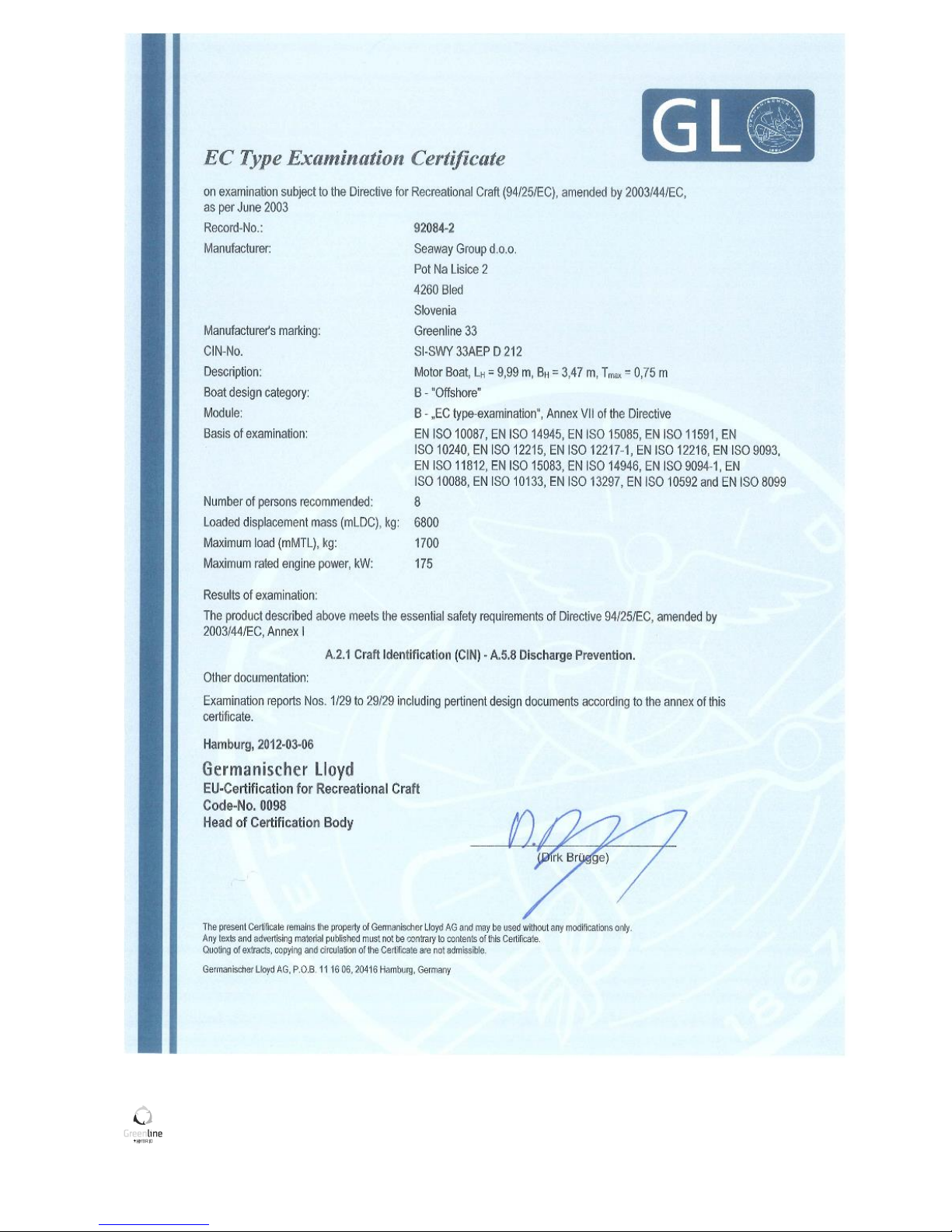
Figure 2: Boat examination report .................................................................................................................... 9
Figure 3: Engine examination certificate (VW SDI 75-5) ................................................................................. 10
Figure 4: Engine examination certificate ( VW TDI 165-5) .............................................................................. 11
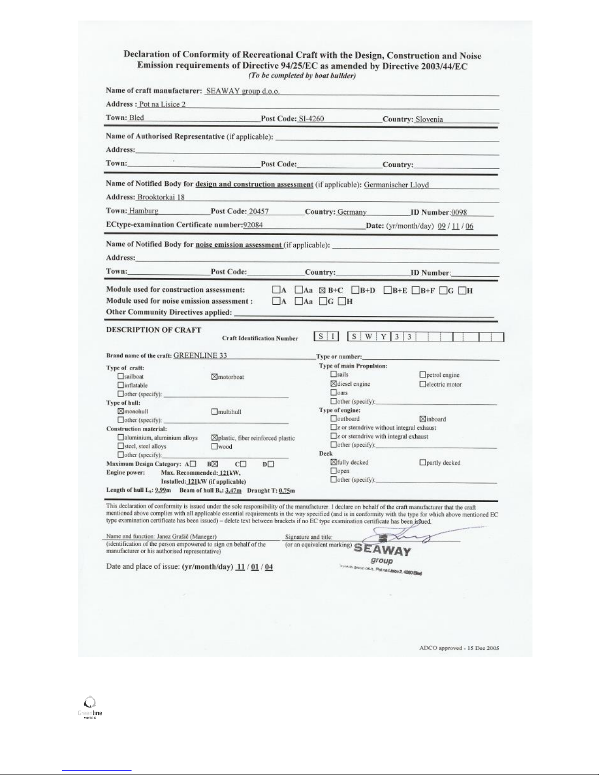
Figure 5: Declaration of Conformity ................................................................................................................ 12
Figure 6: Builders certificate plate................................................................................................................... 14
Figure 7: Liferaft storage location ................................................................................................................... 16
Figure 8: Working deck area plan .................................................................................................................... 18
Figure 9: LPG system plan ............................................................................................................................... 19
Figure 10: Fire extinguishers positions & Emergency exits ............................................................................ 22
Figure 11: Table of symbols ............................................................................................................................. 25
Figure 12: Automatic bilge pump with automatic switch ............................................................................... 26
Figure 13: Manual bilge pump with integral handle in cockpit ....................................................................... 26
Figure 14: Bilge pump system plan .................................................................................................................. 27
Figure 15: Base position for emergency tiller.................................................................................................. 28
Figure 16: Thru hull fitting positions ............................................................................................................... 29
Figure 17: Deck layout ..................................................................................................................................... 33
Figure 18: Anchor winch with chain stopper ................................................................................................... 35
Figure 19: Manual switch for el. platform ....................................................................................................... 37
Figure 20: Latch on the platform ..................................................................................................................... 37
Figure 21: Accomodations ............................................................................................................................... 39
Figure 22: Sea water plumbing ........................................................................................................................ 41
Figure 23: Fresh water plumbing ..................................................................................................................... 42
Figure 24: Grey water plumbing ...................................................................................................................... 43
Figure 25: Black water plumbing ..................................................................................................................... 44
Figure 26: WATER deck filler on PORT side ..................................................................................................... 45
Figure 27: Fresh water pump .......................................................................................................................... 46
Figure 28: Engine with Hybrid drive ................................................................................................................ 77
Figure 29: Engine seawater inlet with water strainer ..................................................................................... 78
Figure 30: Engine compartment air intake ...................................................................................................... 79
Figure 31: Engine compartment air outlet with exhaust blower .................................................................... 79
Figure 32: Engine control lever ........................................................................................................................ 80
Figure 33: Propeller and anodes...................................................................................................................... 81
Figure 34: Fuel system ..................................................................................................................................... 82
Figure 35: FUEL deck filler on STBD side ......................................................................................................... 83
Figure 36: Fuel pre-filter .................................................................................................................................. 84
Figure 37: Steering system .............................................................................................................................. 85

Greenline 33 VI
Figure 38: Position of hoisting cradle and straps ............................................................................................ 88

Greenline 33 VII
TABLE OF PICTURES (ELECTRICAL SYSTEM)
Picture 1: ENGINE and SERVICE main switch ................................................................................................... 49
Picture 2: HYBRID DRIVE and HYBRID/HOUSE main battery switch ............................................................... 50
Picture 3: BOWTHRUSTER (optional) switch in the cabin ............................................................................... 50
Picture 4: 24h CONSUMERS on the right side; 230Vac CONSUMERS on the left side .................................... 50
Picture 5: INVERTER switch – Phoenix multi control on the dashboard ......................................................... 51
Picture 6: Phoenix multi control ...................................................................................................................... 56
Picture 7: Parallel switch ................................................................................................................................. 60
Picture 8: 12V main switches .......................................................................................................................... 62
Picture 9: Bowthruster switch ......................................................................................................................... 62
Picture 10: 48V main hybrid switch ................................................................................................................. 62
Picture 11: Location of AC/DC panel ............................................................................................................... 63
Picture 12: AC/DC panel .................................................................................................................................. 63
Picture 13: Main 12V power box ..................................................................................................................... 67
Picture 14: Service box fuses ........................................................................................................................... 67
Picture 15: Mooring box fuses ......................................................................................................................... 68
Picture 16: Mooring box (located under the bed in the cabin); anchor winch fuse ....................................... 68
Picture 17: Shore power fuse .......................................................................................................................... 69
Picture 18: LiPo battery bank main fuse .......................................................................................................... 69
Picture 19: Hybrid box fuses ............................................................................................................................ 70
Picture 20: Hybrid control unit main fuse ....................................................................................................... 70
Picture 21: 12V socket on console................................................................................................................... 71
Picture 22: Kitchen 230V sockets .................................................................................................................... 72
Picture 23: Salon 230V sockets above port locker .......................................................................................... 72
Picture 24: Cabin 230V sockets under the port bed ........................................................................................ 72
Picture 25: Toilet 230V socket ......................................................................................................................... 72
Picture 26: Shore power cable (230V input) and main fuse ............................................................................ 73

Greenline 33 1
1. INTRODUCTION
INTRODUCTION FOR THE OWNER'S MANUAL
This manual has been compiled to help you to operate your craft with safety and pleasure. It contains details
of the craft; the equipment supplied or fitted its systems and information on its operation. Please read it
carefully, and familiarise yourself with the craft before using it.
This owner’s manual is not a course on boating safety or seamanship. If this is your first craft, or you are
changing to a type of craft you are not familiar with, for your own comfort and safety, please ensure that you
obtain handling and operating experience before "assuming command" of the craft. Your dealer or national
sailing federation or yacht club will be pleased to advise you of local sea schools, or competent instructors.
Ensure that the anticipated wind and sea conditions will correspond to the design category of your craft, and
that you and your crew are able to handle the craft in these conditions.
Even when your boat is categorised for them, the sea and wind conditions corresponding to the design
categories A, B, and C range from severe storm conditions for Category A, to strong conditions, for top of
category C, open to the hazards of a freak wave or gust, and are therefore dangerous conditions, where only a
competent, fit and trained crew using a well maintained craft can satisfactorily operate.
This owner's manual is not a detailed maintenance or trouble shooting guide. In case of difficulty, refer to the
boat builder or his representative. If a maintenance manual is provided, use it for the craft's maintenance.
Always use trained and competent people for maintenance, fixing or modifications. Modifications that may
affect the safety characteristics of the craft shall be assessed, executed and documented by competent
people. The boat builder cannot be held responsible for modifications he has not approved.
In some countries a driving licence or authorisation are required, or specific regulations are in force.
Always maintain your craft properly and make allowance for the deterioration that will occur in time and as a
result of heavy use or misuse of the craft.
Any craft – no matter how strong it may be, can be severely damaged if not used properly. This is not
compatible with safe boating. Always adjust the speed and direction of the craft to sea conditions.
If your craft is fitted with a life raft, read carefully its operating manual. The craft should have onboard the
appropriate safety equipment (lifejackets harness, etc.) according to the type of craft, weather conditions,
etc., these equipments are mandatory in some countries. The crew should be familiar with the use of all safety
equipment and emergency manoeuvring (man overboard recovery, towing, etc), sailing schools and clubs
regularly organise drill sessions.
All persons should wear a suitable buoyancy aid (Life jacket/Personal Floatation Device) when on deck. Note
that in some countries it is a legal requirement to wear a buoyancy aid that complies with their national
regulations at all times.
This manual is meant to help you enjoy and sail your boat comfortably and safely. It includes hints about the
boat, the equipment and systems delivered or installed and operation and maintenance guidance. Before you
put to sea, read it carefully if you really want to have fun and avoid damage and trouble. Read carefully and
make yourself at home on the boat, before you sail it.
We keep improving our boats as we want you to benefit from technological breakthroughs, new equipment or
materials and our own experience; therefore, the characteristics and information provided may vary without
notice or updating obligation.
Greenline 33 2
This manual is designed in accordance with the ISO 10240 Standard requirements.
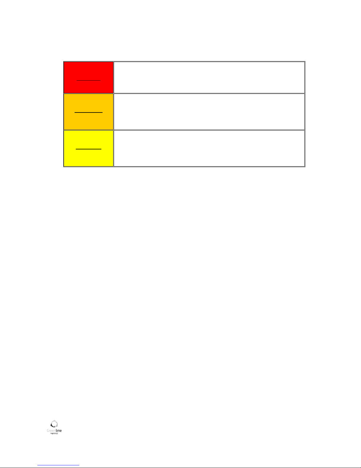
DEGREES OF DANGERS
The following degrees of danger are used in the manual:
DANGER!
Denotes an extreme intrinsic hazard exists which would result in high
probability of death or irreparable injury if proper precautions are not
taken.
WARNING!
Denotes a hazard exists which can result in injury or death if proper
precautions are not taken.
CAUTION!
Denotes a reminder of safety practices or directs attention to unsafe
practices which could result in personal injury or damage to the boat or
components.
This is a broad-line manual which may describe equipment or accessories, or address subjects which do not
concern your boat; in case of doubt, you should check with the inventory submitted upon delivery of your
boat.
If this is your first boat or if you are changing to a boat type which is new to you, before "taking command",
get some training on boat control and sailing, to ensure your safety and comfort. Your dealer, international
sailing association, or yacht club will be pleased to suggest local sailing schools or professional instructors.
Even if everything has been provided for and designed for the safety of the boat and the safety of her users, do
not forget that sailing highly depends on the weather conditions, the sea condition and that only an
experienced and very fit crew, handling a well-maintained boat can sail satisfactorily.
The sea and wind conditions that correspond to the design categories (A, B or C) are changeable and are
dependent on the hazards of unusually strong waves or gusty winds. Therefore a total safety cannot be
guaranteed, even if your boat meets the requirements of a category.
Always listen to the weather forecast before you go out to sea.
Make sure that the sea and wind conditions will correspond to the category of your boat, and that you and
your crew are able to handle the boat in these conditions.
The sea and the water are not the natural environment of Man and one has only to respect their laws and
strength. Adapt the use you make of your boat to her condition; your boat wears out with time and use.
Any boat, however solid she may be, may be severely damaged if badly used. This is not compatible with a
secure navigation. Always adapt the speed and direction of the boat to the conditions of the sea.
The " COLREG ", an international regulation in order to prevent collision at sea, published by the International
Maritime Organization, specifies the helm and course regulations, the navigation lights etc.. all over the world.
Make sure you know these regulations and you have on board a manual that explain them.
In numerous countries, a licence, an authorization or a training course are requested. Make sure you have this
legal authorization before you use the boat.

Greenline 33 3
Always apply to an experienced professional for the maintenance, the assembly of accessories and minor
modifications. The written authorization of the builder or of his legal representative is compulsory for the
modifications that alter the specifications of the boat particularly the vertical layout of the masses (fitting of
radar, change of engine, etc...).
For the essential or optional equipments (engine, electronics ....), please refer to their respective manuals
delivered with the boat.
The users of this boat are informed of the following:
- The entire crew must have an appropriate training;
- The boat must not be loaded more than the maximum load recommended by the builder (in particular
as for the total weight of the food supplies, of the different equipments that are not supplied by the
builder and the weight of the persons on board) and this load must be properly distributed;
- The water of the bilges must be kept at its minimum;
- The stability is reduced when you add some weight in the upper parts;
- In case of rough sea, the hatches, lockers and doors must be closed in order to minimize the risk of
water coming in;
- The stability may be reduced when you tow a boat or when you lift heavy weights with the davits or
the boom;
- Breaking waves are important dangers to stability;
- The crew must be familiar with the use of all the safety equipment (harness, flares, life- raft, etc...) and
the emergency safety handlings (man overboard fishing out, towing, etc...).
PLEASE KEEP THIS MANUAL IN A SECURE PLACE, AND HAND IT OVER TO THE NEW OWNER WHEN YOU SELL
THE CRAFT."

Greenline 33 4
2. SPECIFICATION & WARRANTIES
SPECIFICATION
Parameter
Symbol
Units
Value
Length
maximum length
L
MAX
m
9,99
length of hull
LH m
9,99
length of waterline (at DWL)
L
WL
m
9,85
Beam
maximum beam
B
MAX
m
3,49
beam of hull
BH m
3,47
beam of waterline (at DWL)
B
wl
m
3,07
Depth
maximum depth
D
MAX
m
2,02
midship depth
D
LWL/2
m
1,86
Freeboard
freeboard forward
FF m
1,56
freeboard midship
FM m
1,31
freeboard aft
FA m
1,09
Draught
canoe body draught
TC m
0,575
maximum draught (LDC displacement)
T
MAX
m
0,750
Height
air draught (at DWL,excluding antenna)
HA m
3,10
Displacement
volume displacement (at DWL)
VD kg
5700
light craft condition mass (LCC)
m
LCC
kg
5100
minimum operation condition (MOC)
m
MCC
kg
5310
loaded craft mass (LDC)
m
LDC
kg
6800
maximum load
m
MTL
kg
1700
immersion (at DWL)
kg/cm
209
Engine
number of engines
1
model
VW SDI 75-5
maximum power at crankshaft
kW(HP)
55(75)
maximum speed of crankshaft
RPM
3600
dry weight
kg
245
model (option)
VW TDI 230-6
maximum power at crankshaft (option)
kW(HP)
175(230)
maximum speed of crankshaft (option)
RPM
4200
dry weight (option)
kg
330
Performance
maximum design speed (loaded craft)
kts
15
Batteries
HYBRID (LiPo); (option)
Ah (V)
240(48)
ENGINE (Lead Acid)
Ah (V)
100(12)
SERVICE (AGM)
Ah (V)
130(12)
Tankage
fuel tank STB
L 250

Greenline 33 5
fuel tank PORT
L 250
water tank STB
L 150
water tank PORT
L 150
water heater
L 25
black tank
L 60
grey tank (option)
L 137
Passengers/Crew
crew/passengers
8
Certification
EU RCD category
B ˝Offshore˝
General specifications (ISO8666)
The engine is the main propulsion means of the GREENLINE 33.
Boat builder: SEAWAY YACHTS – RC NMPT d.o.o.
Puconci 80
SI - 9201 PUCONCI
SLOVENIA
Phone: + 386 4 527 77 00
Fax: + 386 4 527 77 20
Web: www.greenlinehybrid.com
Email: info@greenlinehybrid.com
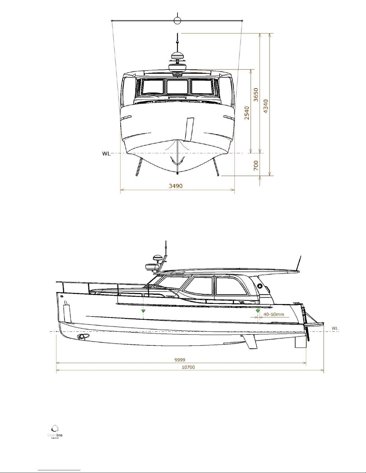
Greenline 33 6
Figure 1: Boat main dimensions

Greenline 33 7
WARRANTY GUIDELINES
1. GENERAL WARRANTY CONDITIONS*
A. Warranty against osmosis is valid for 5 years
B. Warranty that the yacht is free from defects of workmanship (outfit and installation of systems, structural
engineering and lamination) is valid for 2 years under condition that after first 12 months from the delivery the
yacht has been examined by the Dealer (Builder) and the warranty hereby extended for the next 12 months.
*see B. DEROGATIONS below.
2. WARRANTY DETAILS
A. DEFINITONS
The warranty starts from the date of delivery and is strictly limited at the exclusive Builder’s discretion to the
replacement/repair without indemnification whatsoever of any parts which have been defined as defective by
the Builder.
B. DEROGATIONS
However in derogation with the above mentioned GENERAL WARRANTY CONDITIONS are as follows:
1) Warranties on structural elements and workmanship are limited to 1 year with respect to boats used for
professional purposes (as charter, fishing, work boats, etc.)
2) Warranty on parts that deteriorate rapidly due to wear and tear, including but not limited to 12 V batteries,
external decorations, cushions, hull bottom protection, etc. is limited to 1 year.
C. VALIDITY
The warranty is only valid after the acceptance the Delivery certificate by the Dealer/Agent.
D. CLAIM PROCEDURE
1) NOTIFICATION
In order to be covered by the contractual warranties, the Dealer/Agent must provide a written notification to
the Builder accompanied by evidence in form of photo, written report, independent export report or any other
document that may assist in assessing the claim. Notification must be detailed and precise and provided within
15 days the defect is discovered.
The failure to notify the Builder within 15 days will result in Dealer’s/Agent’s liability for the consequences of
this delay.
2) TRANSPORTATION
The costs of transporting the boat or any defective part as well as any additional related costs due to
impossibility of using the boat and/or her equipment are to be borne exclusively by the Agent/Dealer.
3) EXTENTION OF WARRANTY

Greenline 33 8
The application of any the warranties prolongs the corresponding warranty period for the part or
accessory thus repaired or exchanged, during a period equal to the necessary time to perform the warranty
work only, provided that said work necessitates at least 7 consecutive days of labour to be performed.
E. NON-WARRANTY CLAIMS
The following and potential consequences thereof are specifically excluded from the warranty:
1) effects of normal wear
2) varying effects of climatic and environmental conditions, airborne chemicals, salt and use conditions
3) gel-coat fissures, cracks or discoloration
4) deterioration of parts that were replaced by inadaptable parts, or from another origin or which were
modified or repaired, even partially by a shop not authorized by the Builder
5) damages resulting from:
* non observance of maintenance recommendations as described in the Owner’s Manual submitted
with the boat or non compliance with the normal rules of boat maintenance;
* improper use, especially negligent, reckless, abusive or abnormal use;
* negligence with regards to the use of protective measures when necessary;
* an accident such as collision or grounding, improper docking or mooring, transportation, sailing in
adverse weather conditions, or disaster such as explosion, fire, storm, lightning, riot, theft or shock.
F. EXPANSION OF WARRANTY
The dealers, agents or re-sellers of the Builder are not qualified to modify the above mentioned warranty, but
are authorized for their own account and under their sole responsibility to grant other warranties that would
in no way be under the Builder’s responsibility.
Greenline 33 9
Figure 2: Boat examination report

Greenline 33 10
Figure 3: Engine examination certificate (VW SDI 75-5)

Greenline 33 11
Figure 4: Engine examination certificate ( VW TDI 165-5)
Greenline 33 12
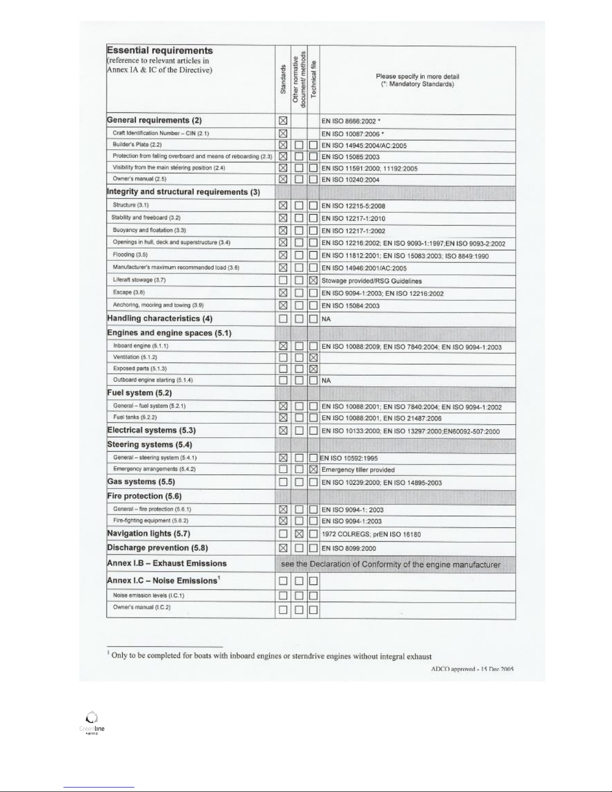
Figure 5: Declaration of Conformity
Greenline 33 13
Greenline 33 14
WARNING!
Do not exceed the maximum recommended number of persons.
Regardless of the number of persons on board the total weight of
persons and equipment must never exceed the maximum
recommended load. Always use the seats/seating spaces provided.
WARNING!
When loading the craft, never exceed the maximum recommend load.
Always load the craft carefully and distribute loads appropriately to
maintain design trim (approximately level). Avoid placing heavy weights
high up.
DEFINITION OF THE DESIGN CATEGORIES: CATEGORY B
A boat given design category B is considered to be designed to operate in winds up to Beaufort force 8 and the
associated wave heights. Such conditions may be encountered on offshore voyages of sufficient length or on
coastal waters when unsheltered from the wind and waves for several dozens of nautical miles. These
conditions may also be experienced on inland seas of sufficient size for the wave height to be generated.
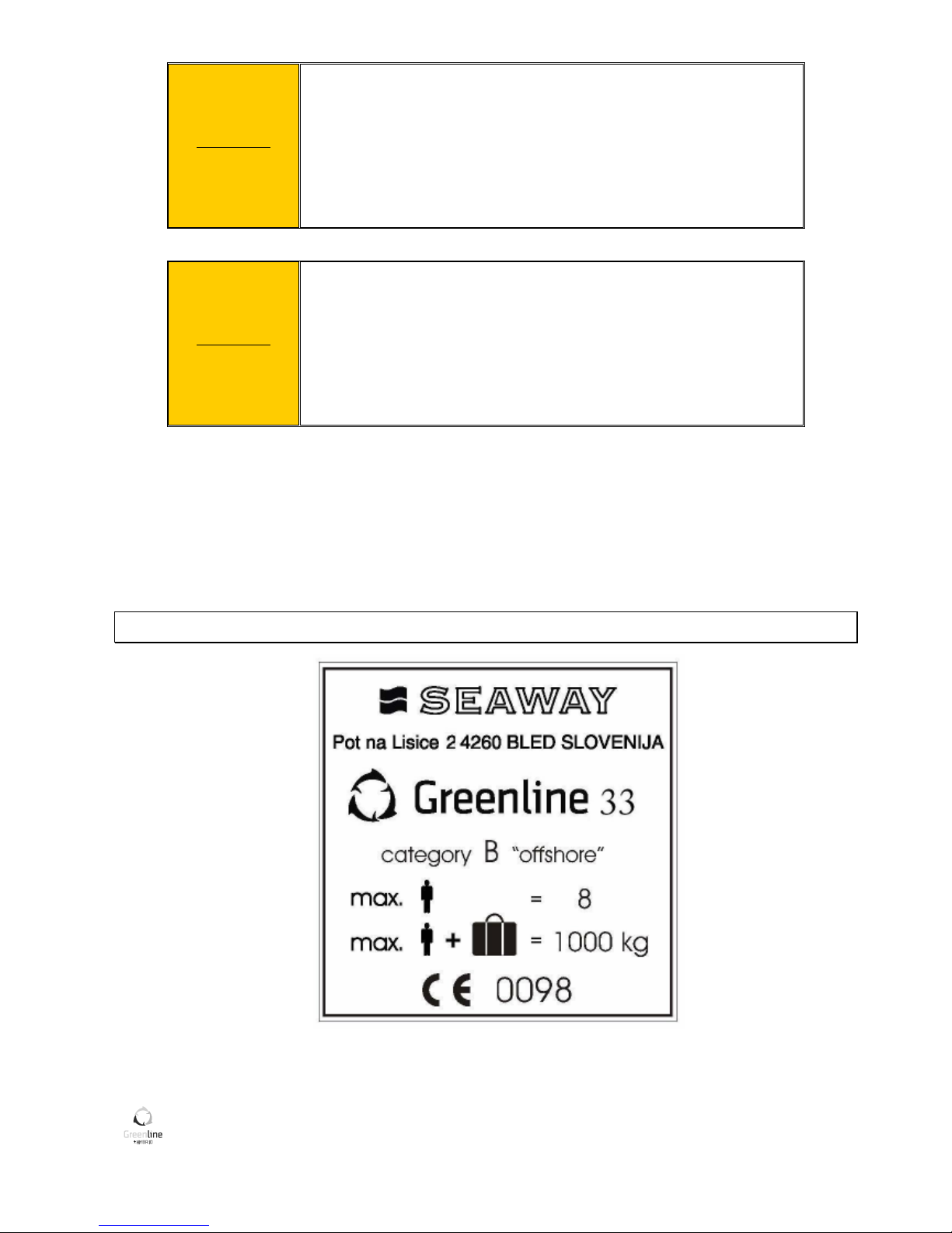
BUILDER’S PLATE
Figure 6: Builders certificate plate

Greenline 33 15
REGISTRATION DETAILS
NAME OF BOAT
OWNER’S NAME
ADDRESS
HULL NUMBER
CIN CODE
REGISTRATION NUMBER
ENTRANCE KEY NUMBER
ENGINE TYPE
ENGINE SERIAL NUMBER
GEARBOX SERIAL NUMBER
HYBRID DRIVE SERIAL NUMBER
ENGINE KEY NUMBER
DATE OF DELIVERY
COMMISSIONING DISTRIBUTOR
NAME OF DISTRIBUTOR
ADDRESS
TELEPHONE NUMBER
FAX NUMBER
Greenline 33 16
3. SAFETY
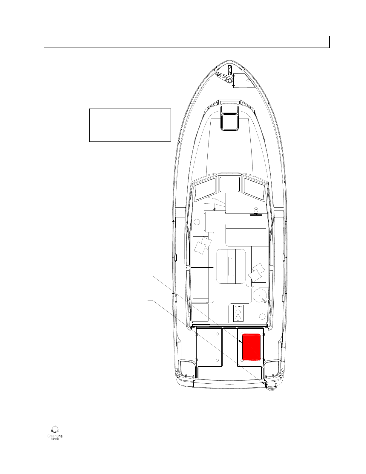
LIFE RAFT STORAGE
1
Swimming ladder (means
of comming back onboard)
2
Position of the liferaft
(not supplied)
1
2
Figure 7: Liferaft storage location

Greenline 33 17
SAFETY EQUIPMENT
RECOMENDATION!
The launching procedure is indicated on the raft and should be read carefully before putting
to sea.
WARNING!
Check the safety equipments inventory before each trip.
RECOMENDATION!
We advise you to close the deck hatches and portholes before each trip.
We advise you the following: Do not store anything below the floorboards.
Greenline 33 18
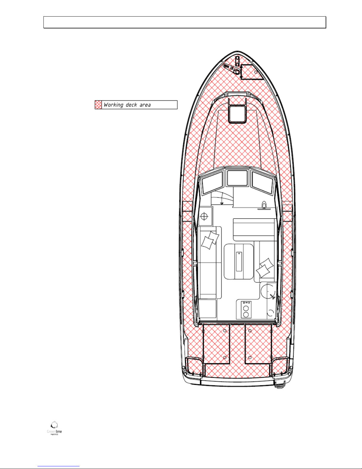
MAN OVERBOARD PREVENTION AND RECOVERY
Figure 8: Working deck area plan
Greenline 33 19
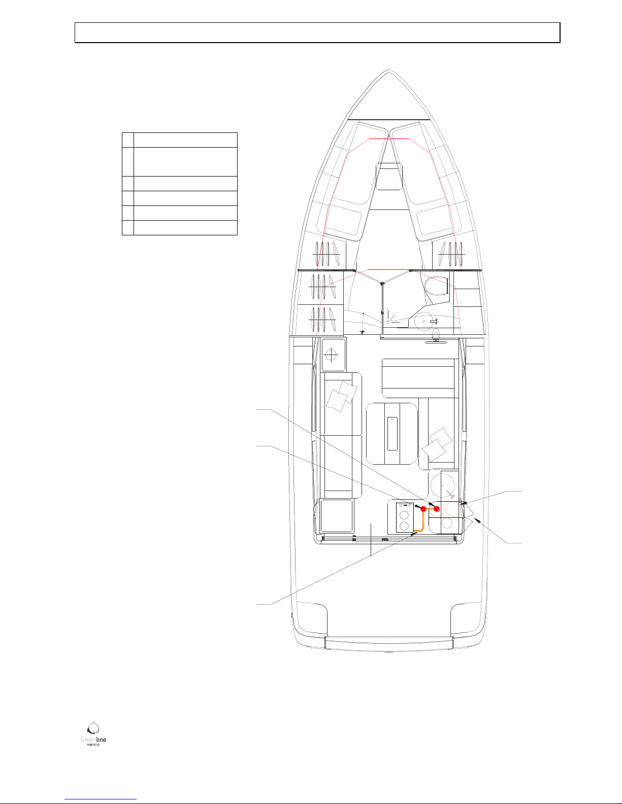
LPG SYSTEM
2
1
4
3
5
5
Gas cylinder valve
6
Cooker-oven
1 Gas cylinder
2
3
4
Gas hose
Gas circuit valve
Ventilated gas
cylinder compartment
Figure 9: LPG system plan

Greenline 33 20
SAFETY DIRECTIONS CONCERNING GAS STOVE
Shut the valves in the system and on the cylinder when the appliances are not in use. Close the valve before
any change of cylinder and immediately in case of emergency. Never leave appliances burning unattended.
Do not fit or store flammable materials above or over the stove (curtains, papers, napkins, and so on...).
Be sure that the valves of the appliances are turned off before you turn on the valves of the gas cylinder or of
the hoses.
If you smell gas or find that the burners have gone out, by accident (although appliance models cut off
automatically if the flames go out) turn off the gas taps and do ventilate the boat in order to get rid of any
residual gas. Find the cause of the problem.
Regularly test the gas system for leaks.
Shut the appliance valves and open the cylinder and check all connections for leaks with soapy water or a
detergent solution. In case of leak, shut the cylinder valve and repair before using the cylinder again.
The appliances burns oxygen in the cabin and releases combustion gases, therefore ventilation is mandatory
when the appliances are used.
Don't obstruct the ventilation holes and at least leave the door open.
Don't use the oven or cooker for cabin heating.
Immediate access to the gas system components must be unobstructed at all times. Empty cylinders must be
disconnected and their valves must be shut. Keep the protective covers, plugs and hatches in place.
Store the empty or spare bottles on the deck or in a locker, if ventilated to the outside. Do not use the gas
cylinder storage space to store any other equipment and never store the gas cylinders in another place.
Test the LPG system for leakage regularly. Check all connections for leakage by
- routine observation of the bubble- leak detector (if fitted with a detector),
- observation of the pressure gauge for pressure drop with appliance valves closed and cylinder valve
opened, then closed (if fitted with gauge on supply pressure side),
- manual leak testing,
- testing with soapy water or detergent solution (with appliance burner valves closed and cylinder and
system valves open).
CAUTION! Do not use solutions containing ammonia.
WARNING!
NEVER USE FLAME TO CHECK FOR LEAKS
Greenline 33 21
WARNING!
Fuel-burning open-flame appliances consume cabin oxygen and release
products of combustion into the craft. Ventilation is required when
appliances are in use. Open designated vent openings while appliances
are in use. Do not use the stove or oven for space heating. Never
obstruct ventilation openings.
WARNING!
Never leave craft unattended when LPG consuming appliances are in
use.
Do not smoke or use open flame when replacing LPG cylinders.
Pay particular attention to keep in good condition the screw thread of the cylinder on which the regulator is.
Check the condition of the regulator every year and change it if necessary. Use a regulator identical to the
ones that are fitted. Inspect flue pipes at least annually. Replace if deterioration or openings are found.
Do not use the stove when high angles of rolling or sustained angles of heel are likely (if the craft is not
equipped with a gimballed stove). Always apply to an experienced professional for repairs.
DANGER!
It should be noted that gas systems are a potential hazard unless
operated properly.
SUGGESTIONS TO SET THE EXTINGUISHERS
The portable extinguishers are not part of the standard equipment.
It is compulsory that the extinguishers are within 5 meters from the centre of each berth.
An extinguisher shall be within 2 meters from the engine fire port.
An extinguisher or a fire blanket (ISO 1869) shall be within 2 meters from each open flame appliance.
An extinguisher shall be within 1 meter from the helm position.
Extinguishers on GREENLINE 33 are positioned as shown on the drawing and are with minimum capacity of
8A/68B.
The dealer must remove the security pins on the fixed extinguishers when delivering the boat.
Greenline 33 22
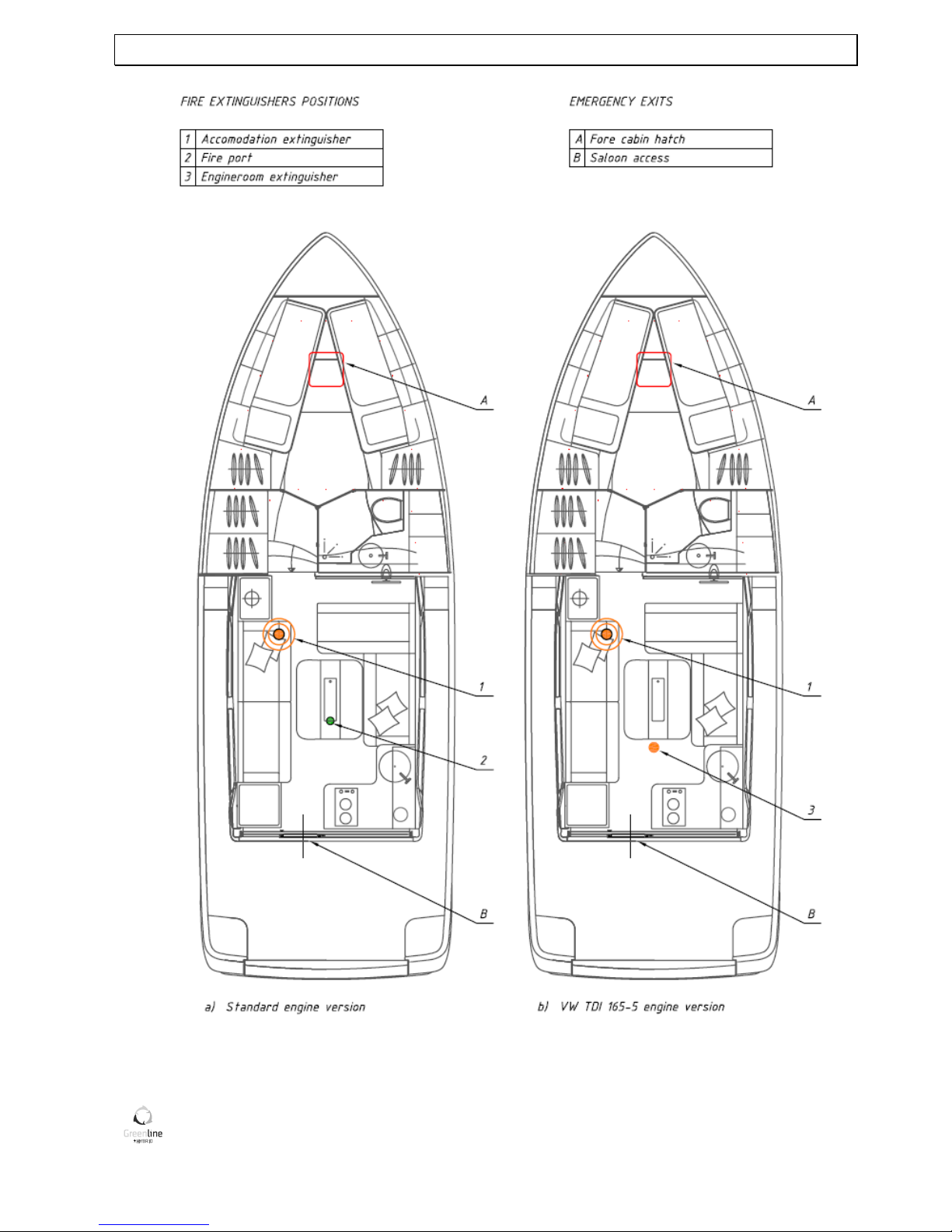
FIGHT AGAINST FIRE & EMERGENCY EXITS
Figure 10: Fire extinguishers positions & Emergency exits

Greenline 33 23
The extinguisher must be located within easy reach and away from possible fire.
The engine compartment includes a fire port to inject the extinguishing agent without opening the normal
access hatch.
The engine compartment (if your boat is equipped with engine stronger than 120kW) is fitted with fixed
extinguisher with automatically activated control.
Your dealer shall have to take the pin out of the extinguisher on receiving the boat.
Steps to be taken in case of fire in the engine compartment:
- Stop the engine,
- Switch off power and shut the fuel supply and close engine room ventilation,
- Inject the extinguishing agent through the aperture or activate fixed fire
Extinguisher (if installed)
- Wait a minute,
- Open the access hatch for access to repairs.
CAUTION!
Keep an extinguisher nearby to react in case the fire should resume.
It is the owner's or the skipper's responsibility:
- To equip the boat with extinguishers.
- To have the extinguishers checked in pursuance of the instructions given.
- To replace the extinguishers by others with an equal or a greater capacity if the extinguishers have
expired or are empty
To tell the crew:
- where the extinguishers are and how they work,
- where the emergency exits are.
- Make sure the extinguishers can be reached easily when people are on board.
 Loading...