

Page 1
www.greenlighting.co.uk • 1 • © Green Lighting Ltd
INSTRUCTION MANUAL
28W 2300lm LED Security Floodlight with PIR
GL-ML28P/BLK & GL-ML28P/WH
The LED Security Floodlight with PIR is an energy efficient outdoor LED floodlight
which detects movement through its built-in PIR sensor. The floodlight is suitable for
installation on solid walls in a range of locations, including entrances, staircases,
gardens, garages and outdoor parking areas
2. Safety Instructions
Please read the following safety information carefully before installing or operating the
floodlight:
The floodlight must be installed by a qualified electrician and checked to ensure that it is safe
before using.
Make sure that the electric power supply is switched off before making wiring connections.
There is a real risk of injury or death while the power supply circuit is live.
Protect all cables against short circuit and overload.
Ensure that the floodlight is connected to an electrical power source of corresponding
voltage.
Do not look directly into the light or point it towards another persons eyes. This light has a
very intense light output which, if correctly used, could cause eye damage.
You can minimise the risk of electric shock by installing appropriate safety devices. (Eg by
incorporating a residual current breaker (RCCB) into the main distribution board).
1. Technical Specifications
Power supply
230V AC - 50Hz
Power usage
28 Watts
Lumens
2300lm
Colour temperature
5700K
PIR range
2 to 10metres - adjustable
PIR detection angle
120º
Ambient light
20 Lux to daylight - adjustable
Activation duration
5 sec to 5 mins - adjustable
Water resistance IP rating
IP65
Page 2
www.greenlighting.co.uk
• 2 •
© Green Lighting Ltd
3. Parts Included
• 1 x 28W LED Security Floodlight with junction box
• 1 x Grommet (installed in junction box)
• 3 x Wall screws (32mm; 1¼)
• 3 x Wall plugs
• 4 x Junction box screws (12mm; ½in)
4. Tools Required
• Electric/hand-held drill
• No. 8 masonry bit
• Electrician’s flat-head screwdriver
• Large Philips screwdriver
• Small Philips screwdriver
• Wire cutters
• Pencil or marker
5. Selecting a Mounting Location
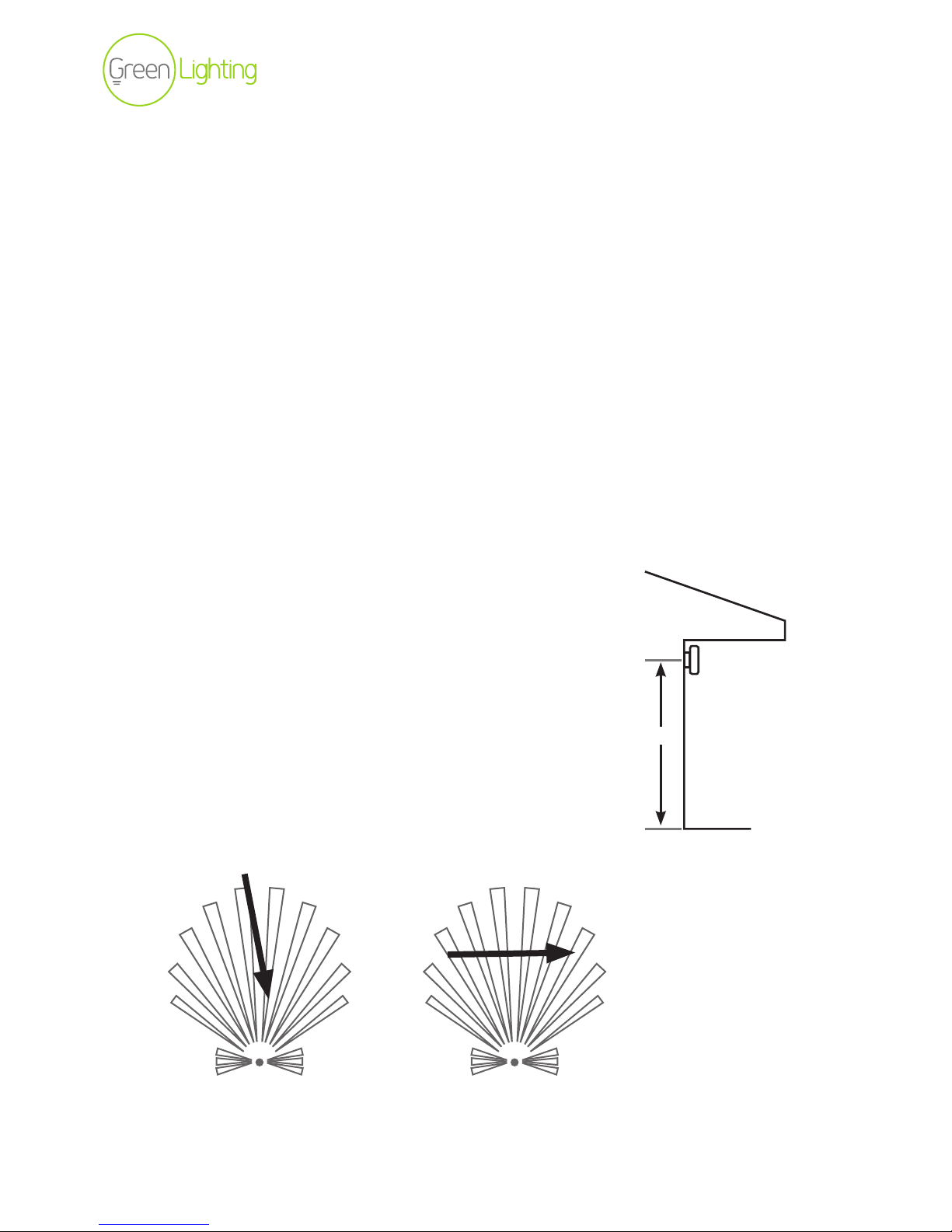
• Mount the floodlight on to a solid wall,
3-5m (10-16ft) above the ground (Fig 1.)
• DO NOT mount the floodlight near heat sources such as
hot ventilator ducts, air conditioning units, street lighting
or traffic, which can interfere with its operation.
• Avoid pointing towards objects that move in the wind, such
as trees or shrubs, or towards highly reflective surfaces.
• When positioning the light note that the PIR sensor is
more sensitive to a heat source moving across its coverage
area and less sensitive to those that move towards the
PIR sensor. (Fig 2.)
3-5 m
Fig 1.
Fig 2.
PIR
sensor
Less sensitive More sensitive
Page 3
www.greenlighting.co.uk
• 3 •
© Green Lighting Ltd
6. Installing the Floodlight
WARNING! Be sure to turn off the power supply to the fuse box before connecting the wires.
There is no safe way to make this connection with a live circuit.
1. Drill a hole in the wall to pass the wires from the power source
2. Hold the mounting base in the desired position on the wall, then mark the locations of the
screw holes. Drill a pilot hole into each screw hole location.
3. Pierce the grommet in the mounting base and thread the cable from the power source
through the grommet.
4. Screw the mounting box onto the wall using the wall plugs and mounting screws provided.
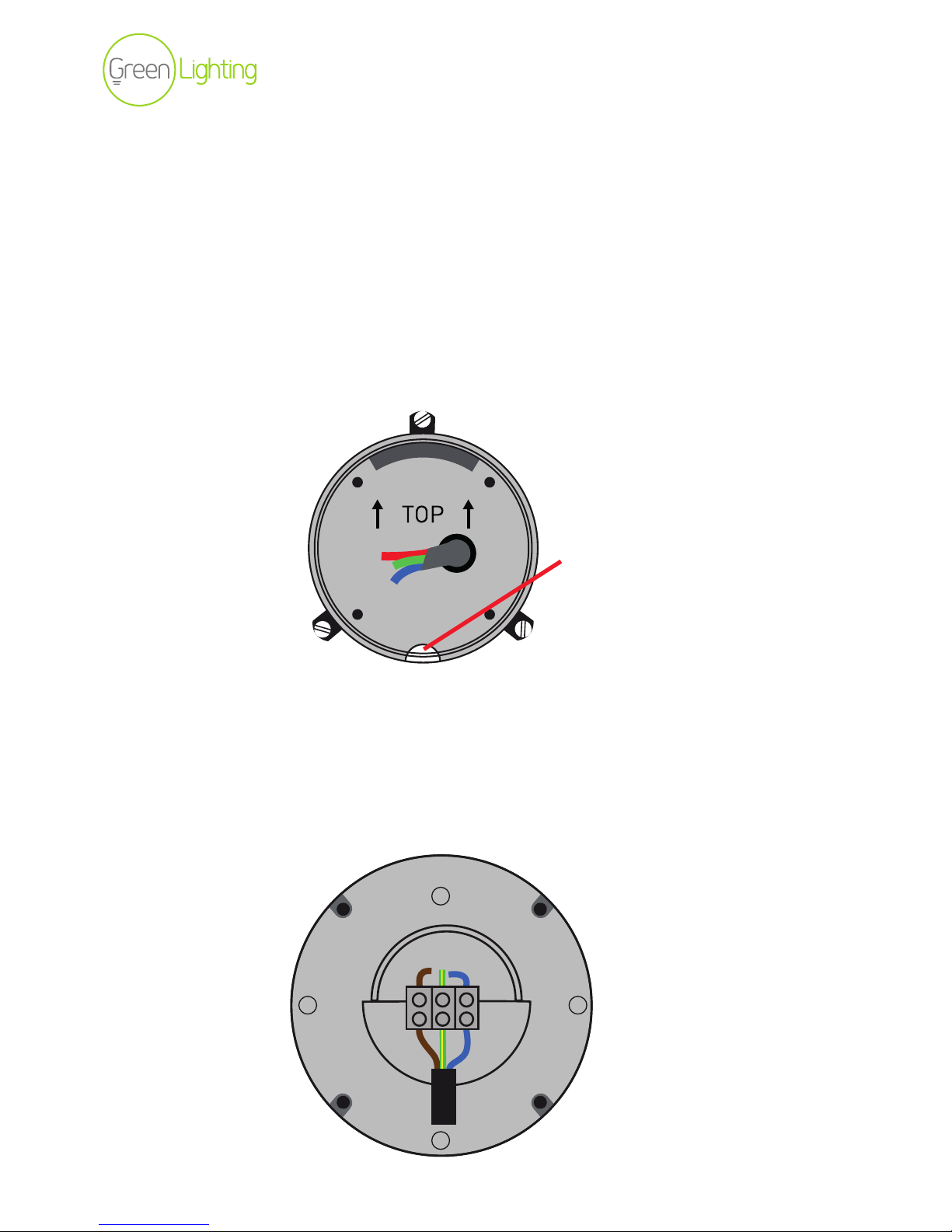
Note: Make sure that the drain is aligned towards the bottom.
5. Strip approximately 6mm (¼ in) of insulation from each of the wires.
Connect the wires to the terminals inside the junction box as follows (Fig 4), ensuring that
no copper remains exposed.
• Connect the BROWN (Live) wire to the terminal with the BROWN wire
• Connect the BLUE (Neutral) wire to the terminal with the BLUE wire
• Connect the YELLOW-GREEN (Earth) wire to the terminal with the YELLOW-GREEN wire
Drain
Fig 3.
Live
E
Neutral
Fig 4.
Page 4
www.greenlighting.co.uk
• 4 •
© Green Lighting Ltd
6. Mount the junction box onto the mounting base.
7. Screw the junction box onto the mounting base using the screws provided.
Note: To adjust the angle of the light assembly slightly loosen the Horizontal and Vertical
fixing bolts.
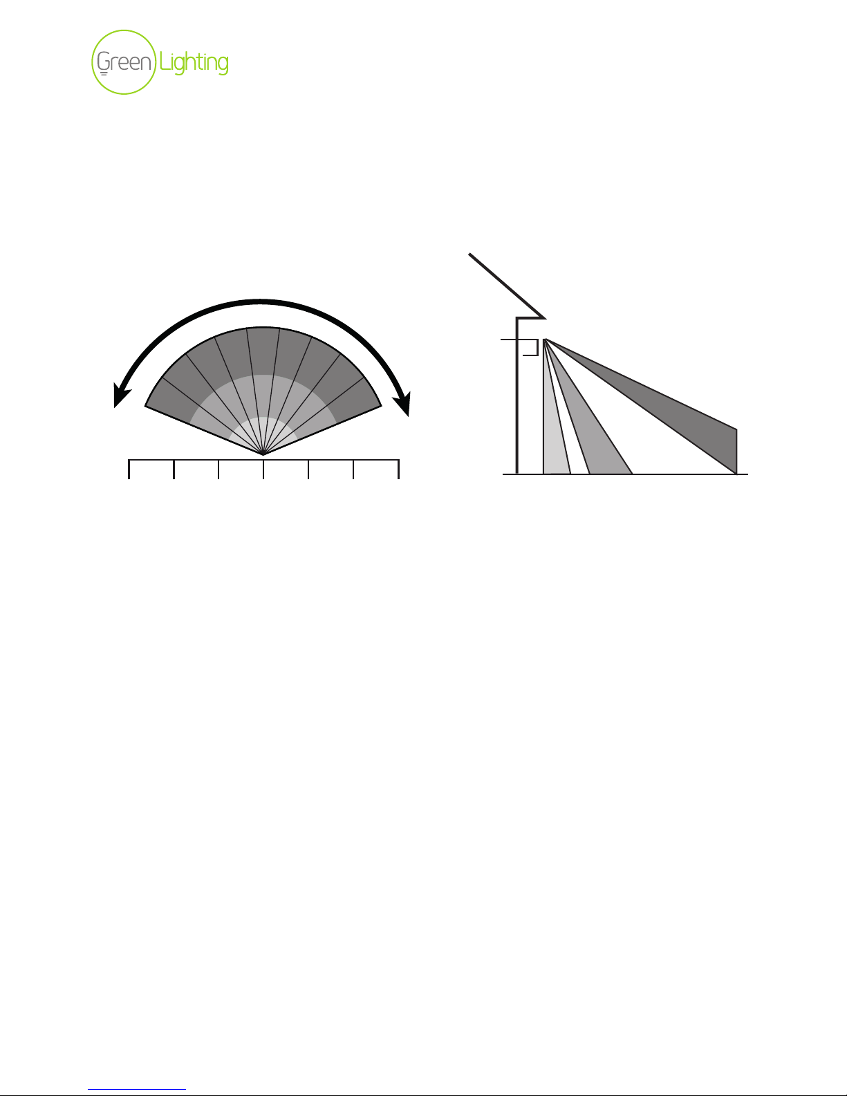
8. Position the light fitting for optimum PIR coverage. (Fig 5)
TOP VIEW TOP VIEW
120º
8-16ft
29ft 19ft 9ft 0 9ft 19ft 29ft 0 9ft 19ft 32-39ft
120º Coverage
Fig 5.
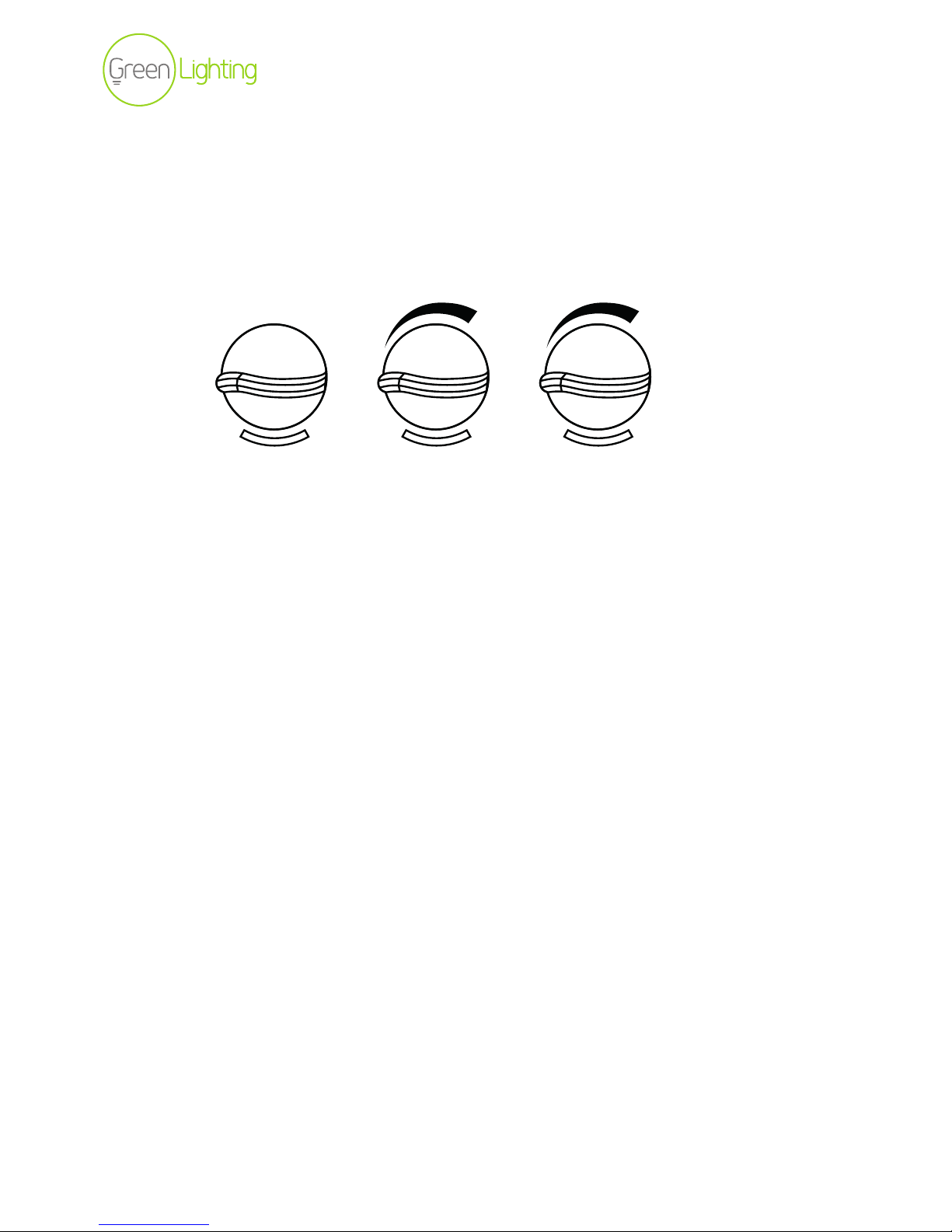
To adjust the angle of the floodlight slightly loosen the clamping knobs, position the head to
the desired angle, then re-tighten the clamping knobs.
Page 5
www.greenlighting.co.uk
• 5 •
© Green Lighting Ltd
7. Setting the Light’s Functions
The light has the following controls (Fig 6).
• F (Lux) - controls the lux/ambient light level at which the light and PIR operate.
• T (Time) - controls the time duration the light turns on when triggered.
• R (Range) - controls the range and sensitivity of the PIR.
See below for instructions on setting the different controls.
7.1 Setting the Lux (Ambient Light Level)
The Lux setting (F) determines the light level at which the light and PIR operate.
• At level 1 it operates in maximum darkness.
• At level 5 it operates in daylight.
7.2 Setting the Time Duration
Turn up the Time Duration control (T) to increase the duration of the light.
• The duration can be set from approximately 5 seconds to 5 minutes.
• If a moving heat source is detected, the sensor is triggered, switching on the light and
starting the countdown to time-out according to the pre-set Time period. If the sensor
is triggered again, the light remains on for the pre-set duration starting from the last
trigger.
• The ideal On time for general domestic situations is 2 - 3 minutes.
7.2 Setting the Range
The Range sensitivity of the PIR (R) is affected by the range of detection and the amount
of infrared radiation (heat) required to trigger the sensor.
• The Range sensitivity adjustment can also be use to compensate for the changes in
outside air temperature in winter and summer.
• To be effective, yet minimise nuisance triggering, it is advisable to turn the
Range control to the middle position where the ambient air temperature is between
15 - 20ºC.
2 4
3
1 5
F T R
Fig 6.
Page 6

www.greenlighting.co.uk
• 6 •
© Green Lighting Ltd
8. Testing the Floodlight
To perform the test during the day, turn the Time control(T) to minimum and the ambient light
control (F) to 5 (maximum light). To perform the test during the night, turn the Time control (T)
to minimum and the ambient light control (F) to 1 (maximum darkness) (See Fig 6).
1. Turn on power to the floodlight. The floodlight turns on for approximately 5 seconds before
switching off.
2. Verify the operation of the sensor and the field of view by walking in front of the floodlight
so that the light comes on.
3. With the light still on, move to a new position and stand still until the light goes off
(approximately 5 seconds), then move again until the light comes back on.
4. Repeat and adjust the angle of the sensor head until the optimum field of view is achieved.
5 Turn the Time, Lux and Range controls to the desired positions for operation.
9. Maintenance & Repairs
• Maintain the light in good condition. (Keep the face clean and do not allow any part to
become damaged).
• Disconnect the floodlight from the power supply before servicing or performing any kind of
maintenance.
• All repairs should be undertaken only by a professional electrician.
• Only use genuine parts for repairs. Non-authorised parts may be dangerous and will void
the warranty.
Page 7
www.greenlighting.co.uk
• 7 •
© Green Lighting Ltd
10. Troubleshooting
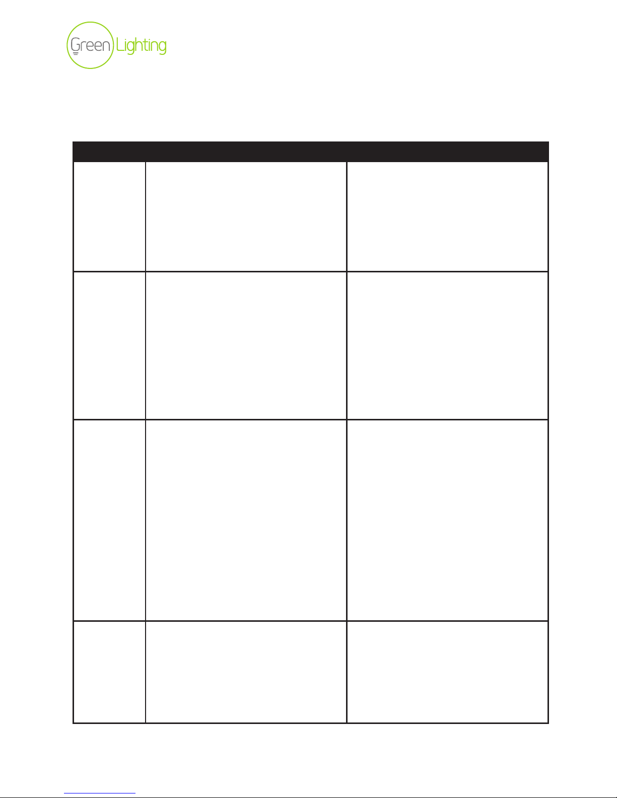
If your Tool Light does not work after following the instructions in this manual please try the
following steps.
Problem Possible Cause Possible Solution
Light fails
to switch
on
• Power is not turned on
• The light is wired incorrectly
• The PIR is not detecting movement
• Ambient light conditions are too
bright
• Turn on indoor switch or check fuse.
• Check wiring is as shown in the
wiring diagram
• Adjust the angle and direction of the
PIR. For best results test by walking
across the beam
Light fails
to switch
off
• The TIME value is set too high
• The light is wired incorrectly
• Frequent changes in heat movement
are being detected
• Turn on Time knob to the left to
reduce the ON time
• Check wiring is as shown in the
wiring diagram
• Check sensing area for possible heat
sources (e.g., air vents, moving
vehicles, moving trees) and
reposition the sensor or alter the
Range control downwards.
Light keeps
turning
on and off
(cycling)
• Changes in heat are being detected
from a fixed heat source
• Changes in heat are being detected
from a moving object
• Light and/or heat are being reflected
back onto the sensor
• Sudden temperature changes due to
storms or high winds
• Check the sensing are for air vents,
light fittings or fans and either
reposition the sensor or adjust the
aim
• Check the sensing are for moving
vehicles, animals, pedestrians and
moving trees and adjust the aim of
the sensor accordingly
• Adjust the aim of the sensor or paint
reflective surfaces with a dull finish
• Turn the sensor off until the storm
passes or install in a sheltered
position
Sensor
operates
differently
in hot and
cold
conditions
• Temperature differences are
affecting the sensitivity of the sensor
• Turn the sensibility (Range) control
knob toward the maximum end
for summer (hot conditions) and
toward the minimum for winter (cold
conditions). This compensates for
variations in temperature
Page 8

www.greenlighting.co.uk
• 8 •
© Green Lighting Ltd
Please note that this equipment and its components have NO user-servicable parts.
If you experience any difficulties, call our helpline:
Green Lighting Helpline Tel: 01905 610200 (Monday - Friday)
www.greenlighting.co.uk
Green Lighting tries to improve its products for the benefit of its customers.
For this reason, we reserve the right to make changes to any product at any time, without notice.
 Loading...