

Page 1
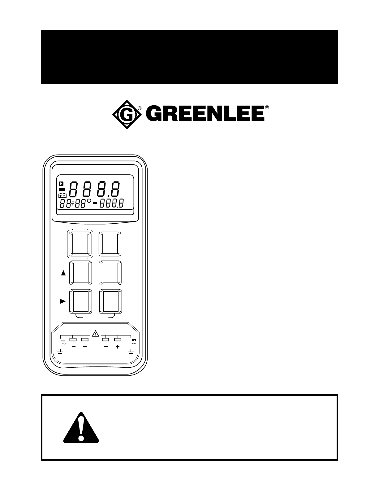
999 3805.7 © 2000 Greenlee Textron IM 1480 12/00
TML-30
TEMPERATURE
METER / LOGGER
INSTRUCTION MANUAL
INSTRUCTION MANUAL
Read and understand all of the instructions
and safety information in this manual before
operating or servicing this tool.
K T1- T2
T1
T2
REC MAX MIN AVG
°C
°F
°C
°F
Down Load
Type K/J THERMOMETER
T1 T2
REL
J
°
C
°
F
CLOCK
MAX
MIN
AVG
REC
ERASE
INTV
SETUP
T1 T2
T1-T2
ON
HOLD
OFF
60V
24V
MAX
60V
24V
MAX
Page 2

2
Description
The Greenlee TML-30 is a hand-held testing device intended to measure temperature (Celsius
and Fahrenheit). It can accommodate one or two K-type or J-type thermocouples, purchased
separately, and has a built-in memory for logging measured data.
Once data is collected in the meter, it can be downloaded to a PC (software and cable included)
where the data can be viewed in a list or a graph, saved to a file, and exported to a spreadsheet
application such as Microsoft Excel®. While the meter is connected to a PC, users can view
real-time readings and record the data on the PC.
Safety
Safety is essential in the use and maintenance of Greenlee tools and equipment. This
instruction manual and any markings on the tool provide information for avoiding hazards and
unsafe practices related to the use of this tool. Observe all of the safety information provided.
Purpose
This instruction manual is intended to familiarize all personnel with the safe operation and
maintenance procedures for Greenlee TML-30 Temperature Meter / Logger.
Keep this manual available to all personnel.
Replacement manuals are available upon request at no charge.
Greenlee and are registered trademarks of Greenlee Textron.
IBM is a registered trademark of International Business Machines. Windows and Excel are
registered trademarks of Microsoft Corporation.
KEEP THIS MANUAL
Page 3
TML-30
3
Important Safety Information
Read and understand this material before operating or servicing
this equipment. Failure to understand how to safely operate this
tool can result in an accident causing serious injury or death.
This symbol is used to call your attention to hazards or unsafe practices which could
result in an injury or property damage. The signal word, defined below, indicates the
severity of the hazard. The message after the signal word provides information for
preventing or avoiding the hazard.
SAFETY ALERT SYMBOL
Immediate hazards which, if not avoided, WILL result in severe injury or death.
Hazards which, if not avoided, COULD result in severe injury or death.
Hazards or unsafe practices which, if not avoided, MAY result in injury or property
damage.
Page 4
4
Important Safety Information
Electric shock and fire hazard:
• Do not expose this unit to rain or moisture.
• Do not use the unit if it is wet or damaged.
• Use accessories that are appropriate for the application. See the category and
voltage rating of the accessory.
• Inspect the accessory before use. It must be clean and dry, and the insulation must
be in good condition.
• Use this unit for the manufacturer’s intended purpose only, as described in this
manual. Any other use can impair the protection provided by the unit.
Failure to observe these warnings can result in severe injury or death.
Electric shock hazard:
Contact with live circuits can result in severe injury or death.
Electric shock hazard:
• Do not apply more than the rated voltage between any two input terminals, or
between any input terminal and earth ground.
• Do not contact any uninsulated portion of the accessory.
Failure to observe these warnings can result in severe injury or death.
Page 5
TML-30
5
Important Safety Information
• Do not operate with the case open.
• Before opening the case, remove the accessory from the circuit and shut off the unit.
Failure to observe these warnings can result in severe injury or death.
• Do not attempt to repair this unit. It contains no user-serviceable parts.
• Do not expose the unit to extremes in temperature or high humidity.
See Specifications.
Failure to observe these precautions can result in injury and can damage the unit.
Using this unit near equipment that generates electromagnetic interference can result
in unstable or inaccurate readings.
Page 6
6
K T1- T2
T1
T2
REC MAX MIN AVG
°C
°F
°C
°F
Down Load
Type K/J THERMOMETER
T1 T2
REL
J
°
C
°
F
CLOCK
MAX
MIN
AVG
REC
ERASE
INTV
SETUP
T1 T2
T1-T2
ON
HOLD
OFF
60V
24V
MAX
60V
24V
MAX
1
2
3
4
89
5
6
7
RS232
10
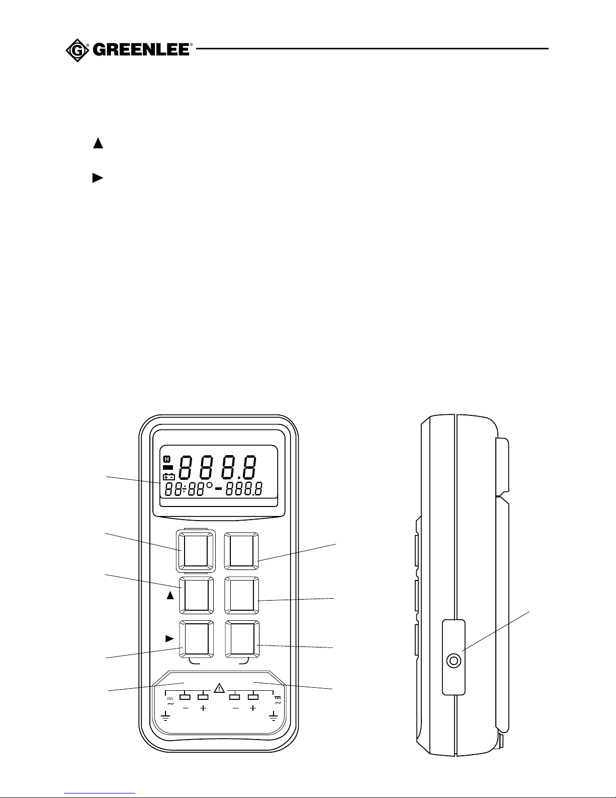
Identification
1. Display LCD
2. ON / HOLD / OFF Press to turn power on or off, or to select the Hold function.
3. MAX / MIN / AVG Press to collect maximum, minimum and average temperatures
over time. Also used to increment during setup.
4. REL / J Press to select Relative Measurement function, or to use a J-type
thermocouple. Also used as cursor advance during setup.
5. T1 / T2 / T1-T2 Press to select the measurement function. Also used to enter
Setup function.
6. REC / ERASE Press to record data; erases the data when the memory is full.
Also used in setup to set the recording interval in seconds.
7. °C / °F Press to select a temperature scale. Also used to set the date and
time in setup.
8. T1 2-pin connector for temperature probe T1
9. T2 2-pin connector for temperature probe T2
10. RS-232 port Personal computer interface
Page 7
TML-30
7
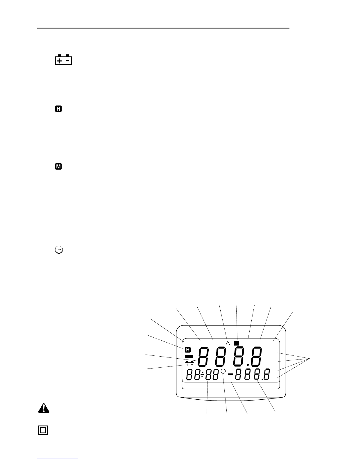
Display Icons
13. Battery low
14. - 888.8 Primary display
OL Overload (the measurement is beyond the capability of the unit)
– - - - - No input from thermocouple
15. Hold Function is enabled
16. K K-type thermocouple is selected
17. T1-T2 Indicates the measurement on the primary display (T1, T2, or T1-T2)
18. REC Indicates that recording is in process
19. ∆ Relative Mode (the difference between two readings) is selected
20. Memory
21. MAX Maximum recorded measurement
22. MIN Minimum recorded measurement
23. AVG Average of the recorded measurements
24. °C °F Celsius or Fahrenheit
25. -000.0 Secondary display
26. T1 T2 Indicates the measurement on the secondary display (T1 or T2)
27. Timer
28. 00-00 / 00:00 Date (shown immediately after pressing ON) and time (shown after the
date disappears)
Symbols
on the Unit
Warning – Read the
instruction manual
Double insulation
K T1-T2
T1
T2
REC MAX MIN AVG
°C
°F
°C
°F
13
14
20
19
18
21
22
24
23
25
28
26
27
15
16
17
M
Page 8

8
Meter Operation
Turning the Meter On and Off
1. Connect temperature probe(s) to the meter.
2. Press ON/HOLD/OFF to turn the meter on. The meter performs a self-test. “tESt” indicates
that the test is in progress. “PASS” indicates that the meter has passed the self-test.
3. To turn the meter off, press and hold ON/HOLD/OFF. The display counts down (3, 2, 1)
and the meter turns off.
4. Release the button.
Holding a Reading
After turning the meter on, readings can be stopped and held. During this time no further readings
are recorded. To hold a reading, press ON/HOLD/OFF. To release the function, press again.
Measuring Maximum and Minimum Temperatures
The TML-30 temporarily stores the maximum and minimum temperature readings of the
primary thermocouple and averages the last ten readings. It also indicates the elapsed time
at which the maximum and minimum readings were taken and how long the mode has been
running. The information in this mode is not recorded in the database.
NOTE: All other functions are disabled while in this mode, except ON/HOLD/OFF.
1. Press T1 / T2 / T1-T2 to select the primary thermocouple.
2. Press MAX/MIN/AVG to start the clock and to record the maximum temperature.
“MAX” appears on the display. The maximum temperature appears in the display and
updates as new values come in. The clock indicates the time into the test the last update
occurred.
3. Press MAX/MIN/AVG to display the minimum value recorded and the time it was taken.
4. Press MAX/MIN/AVG to display the average of the last ten samples. The clock shows how
much time has elapsed since the test began.
5. Press MAX/MIN/AVG again to show the normal display. The maximum/minimum feature
continues to run, indicated by on the display.
6. Press MAX/MIN/AVG to cycle through the readings. To clear the maximum/minimum
feature, press and hold MAX/MIN/AVG until disappears.
Page 9

TML-30
9
Meter Operation (cont’d)
Using the Relative Mode
This mode calculates the difference between two measurements of the primary thermocouple.
While taking a measurement, press REL to set the display to zero. The ∆ icon appears on the
display. Take the second measurement. The value on the display is the difference between the
two measurements. Press again to exit this mode.
Changing the Thermocouple type
The TML-30 defaults to a K-type thermocouple each time it is turned on. To change to J-type,
with the meter turned off, press and hold REL / J while turning the meter on. “J” appears on
the display. The “K”, which normally appears in the upper left corner to indicate a K-type
thermocouple, does not appear.
Selecting the Primary Thermocouple
T1 is the default primary thermocouple and is displayed in the center of the display. T2 is the
default secondary thermocouple and is shown in the lower right. To make T2 primary, press
T1 / T2 / T1-T2 until the display shows “T2”. T1 becomes secondary. Press again to enter the
Difference mode (see below). The secondary display alternately displays “T1” and “T2”. Press
again to return T1 as primary.
Determining the Difference Between the Two Thermocouples
The T1-T2 mode calculates the difference between T1 and T2. Press T1 / T2 / T1-T2 until the display
shows “T1-T2” to enter the Difference mode. The difference appears in the primary display and is
constantly updated as the readings change. Press the button again to return to the normal setting.
Recording Measurements to Memory
Recordings are held in memory as “sets” so that they can be downloaded to a PC using the
Temperature software. Each time you start recording, a set is created in the database. You can
record one sample or record samples continuously. “FULL” on the display indicates that the
memory is full.
The sample rate (Interval) determines how often the reading is recorded to the database.
See Setting the Recording Interval.
1. To record one sample, press and release REC/ERASE. “REC” flashes once on the display.
2. To record continuously, press and hold REC/ERASE for three seconds. “REC” flashes every
second on the display.
3. To stop recording, press the button again.
Erasing the Memory
With the meter off, press and hold REC/ERASE while turning the meter on. “dEL” appears on
the display to indicate that the measurements have been deleted from the memory. The meter
then goes through its self-test.
Page 10

10
▲
▲
▲
▲
▲
Setup
For all settings, begin with the meter turned off. During setup, MAX/MIN/AVG (▲) is used to
increment the selected value. REL / J ( ) is used to move to the next value. Pressing and
holding the buttons increases the rate that the value changes.
Setting the Date and Time
1. Press and hold T1 / T2 / T1-T2 (SETUP).
2. Press and release ON/HOLD/OFF.
3. Release T1 / T2 / T1-T2 after the LCD shows “SEt”.
4. Press °C/°F (CLOCK). The year appears in the Primary display and the last two digits
flash.
5. Press ▲ to change the year.
6. Press to advance to the next digits and press ▲ to change the month.
7. Press to advance to the next digits and press ▲ to change the date.
8. Press to advance to the next digits and press ▲ to change the hour.
Time is set in the 24 hour mode.
9. Press to advance to the next digit and press ▲ to change the minutes.
10. Press °C/°F to save the settings.
OR
Press ON/HOLD/OFF to exit without saving.
Setting the Recording Interval (Sample Rate)
1. Press and hold T1 / T2 / T1-T2 (SETUP).
2. Press and release ON/HOLD/OFF.
3. Release T1 / T2 / T1-T2 after the LCD shows “SEt”.
4. Press REC/ERASE (INTV).
“Int” is shown in the primary display and minutes and seconds
are displayed in the lower left.
5. Press ▲ to set the minutes.
6. Press to advance to the next digits and press ▲ to set the seconds.
7. Press REC/ERASE to save the settings.
OR
Press ON/HOLD/OFF to exit without saving.
▲
Page 11

TML-30
11
Setting Up the Thermometer Software
The Thermometer software allows you to download, view and store recorded data from the
meter, and to set the date and time in the meter. While the meter is connected to a PC, you can
view and record real-time data on the PC.
Installing the Software
1. Start the PC and Windows®.
2. Close all open applications.
3. Insert the K/J Thermometer disk in the 3.5" drive.
4. Click the Windows Start button and then click Run.
5. In the text box, type: A:\setup where “A” is the letter of your 3.5" disk drive.
6. Press ENTER.
7. Follow the on-screen instructions to complete the installation.
Connecting to a PC
1. Turn the TML-30 off.
2. Connect the mini connector of the RS-232 to the TML-30.
3. With the PC turned off, securely connect the other end of the RS-232 cable to COM1 or
COM2 of the PC.
Page 12
12
Running Thermometer
The TML-30 must be connected to the PC and turned on in order to open the Thermometer
program.
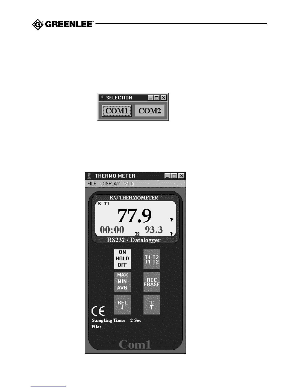
1. Open the Thermometer program. The COM prompt appears.
2. Click the COM port that the meter is connected to. The Thermometer dialog box
appears. Refer to Thermometer Features for a description of each function.
Page 13

TML-30
13
Thermometer Features
• TML-30 image Replicates the front of the TML-30. Real-time values are shown in the
“display.” The temperature is displayed in Celsius or Fahrenheit, depending on the selection
on the meter using the °C / °F button. All commands are performed using the menu bar.
• Buttons Non-functioning
• Sampling Time Shows the current real-time sample rate.
• File When a file name is assigned, its directory path and name are displayed.
• Com Shows the COM port that is connected to the meter.
• Recording Appears when real-time recording begins. Displays the number of recordings
taken.
File Menu
• Save As Opens the Save dialog box.
• Open File Opens the Open dialog box to open an existing file.
• Start Recording Starts recording real-time data to the PC.
• Stop Recording Stops the recording of real-time data to the PC.
Display Menu
• List Displays the data in a list.
• Graph Displays the data in a graph.
Page 14
14
Using Lists
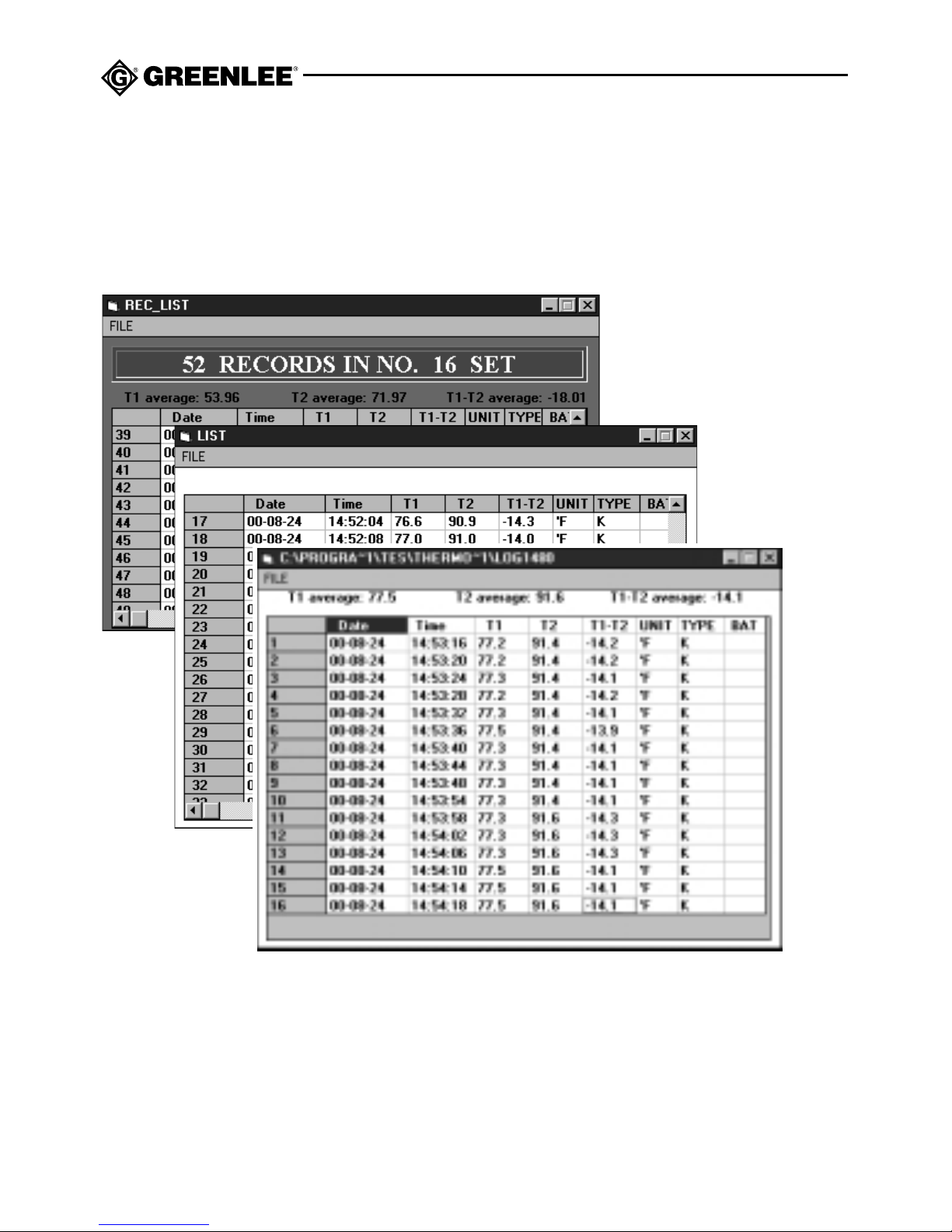
Lists can be accessed from the DISPLAY menu on the THERMOMETER dialog box to view
real-time data and by opening a saved file through the FILE menu. They are also generated
when data in the meter is selected. Essentially, the contents of lists appear and function alike.
However, the menu bar commands have minor differences, depending on where they are
accessed.
List Features
• FILE (real-time) Point to FILE and click one of the following:
CONTINUE Click to resume recording data. Dimmed when the data is being recorded.
PAUSE Click to stop recording incoming data. Dimmed when the recording is paused.
GRAPH Click to display the real-time data in a graph. See Using Graphs.
PRINT Click to print the data.
• FILE (saved data) Point to FILE and click GRAPH or PRINT.
• FILE (data in the meter) Point to SAVE AS to save the file or PRINT to print the file.
Saved
file in
the PC
➞
Real-time data
➞
Data in the meter
➞
Page 15
TML-30
15
Using Graphs
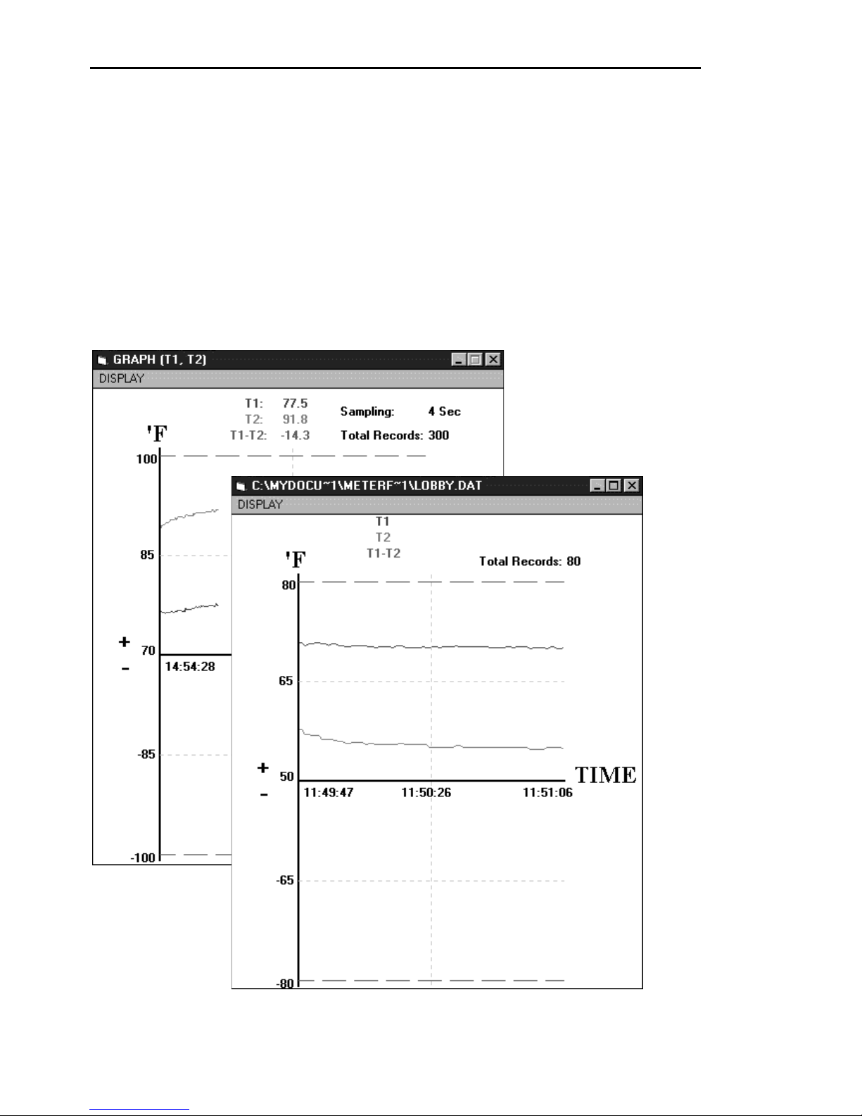
Graphs are accessed from the THERMOMETER dialog box to display real-time data or from the
saved data list to display the contents of the list. The menu commands on the graphs are the
same. However, the titles of the menu commands are slightly different. For example, when you
are using a real-time graph and you point to DISPLAY, the commands T1, T2, or T1-T2 include
the term (DISABLE) or (ENABLE). These terms do not appear on the saved data graph.
Readings in the graph are based on the sampling rate. The graph can be minimized and
restored.
Saved file
in the PC
➞
Real-time data
➞
Page 16
16
Using Graphs (cont’d)
Graph Features
Click on DISPLAY and click one or any of the following:
• T1 (ENABLE/DISABLE)
• T2 (ENABLE/DISABLE)
• T1-T2 (ENABLE/DISABLE)
Clicking any of the above toggles the display for that item.
Note: When viewing a graph from a saved file, DISABLE and ENABLE do not appear as part of
the command.
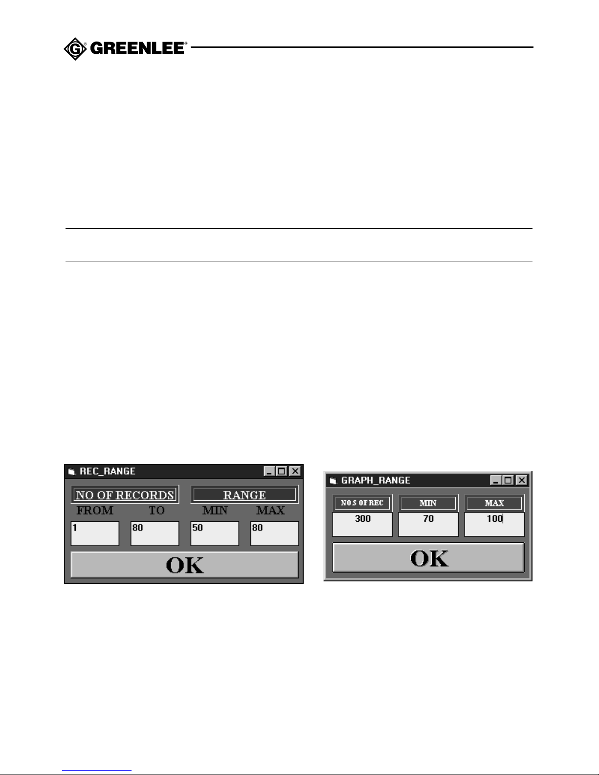
• Limit Click to open the Range dialog box. See Setting the Range of the Graph.
• Print Click to print the current graph.
Setting the Range of the Graph
The number of records that you view and the range of the graph can be easily changed. This
allows you to eliminate unwanted records or to display a certain temperature range so that
you can view specific data. The RANGE dialog box is slightly different, depending on where
the graph is accessed, but functions essentially the same. When setting the range of records
in recorded data, you set which records are displayed. When setting the range of records in
real-time data, you set the quantity of records that are displayed.
1. On the DISPLAY menu, click Limit. A Graph Range dialog box appears.
2. Select the number in each of the text boxes and type in a new value.
3. Click OK. The graph adjusts to the new values.
4. Close the RANGE dialog box.
Real-time dataRecorded data
Page 17
TML-30
17
Downloading Data from the Meter
To view the data that is collected in the TML-30, it must be downloaded to the PC. Once there,
the data can be viewed in a list or graph, saved to a file, and imported into a spreadsheet
program such as Excel.
Note: Downloading the data does not erase it from memory. Data can be repeatedly downloaded until it is erased using the REC/ERASE button on the meter.
1. Follow the steps under Running Thermometer to connect to the PC.
2. Press the Rel / J and °C/°F buttons at the same time. “LOAd” appears on the LCD and
the “display” on the Thermometer dialog box shows the percentage of the completed
download.
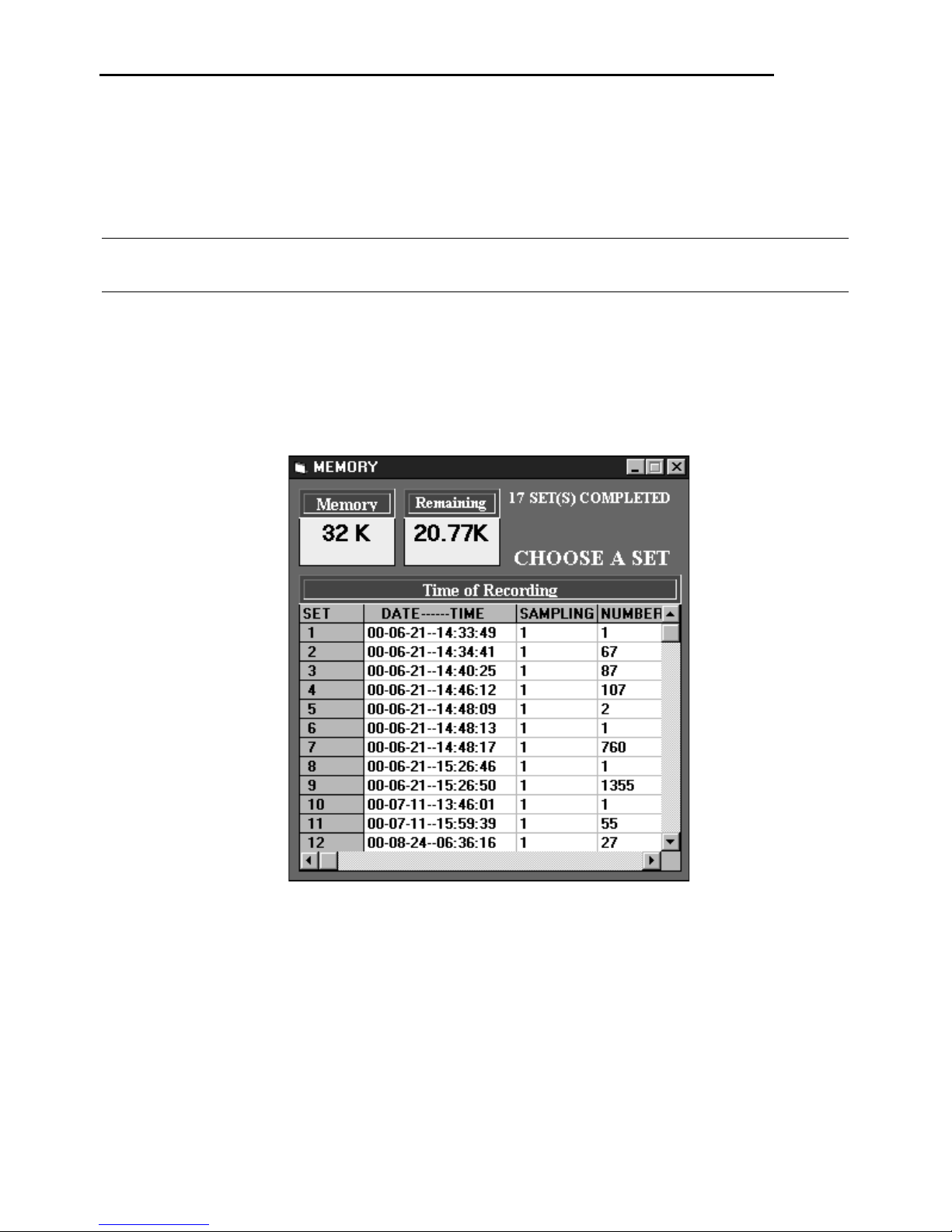
3. Release the two buttons. When the download is complete, the Memory dialog box
appears.
Memory Features
• Memory Shows the total amount of memory in the meter
• Remaining Shows the amount of memory left in the meter
• Time of Recording Displays a list of the sets in the meter
• SET Shows the set number
• DATE - TIME Displays the date the recording was taken and the time in 24 hour mode,
date is YY-MM-DD
• SAMPLING Shows the sample rate that the recording was taken
• NUMBER Shows the number of samples taken in the recording
Page 18
18
Viewing, Printing and Saving Recorded Data from the Meter
1. From the Memory dialog box, click anywhere in a row of a set to select it.
The REC_LIST appears with the data. See Using Lists.
2. To print the data, on the list FILE menu, click PRINT.
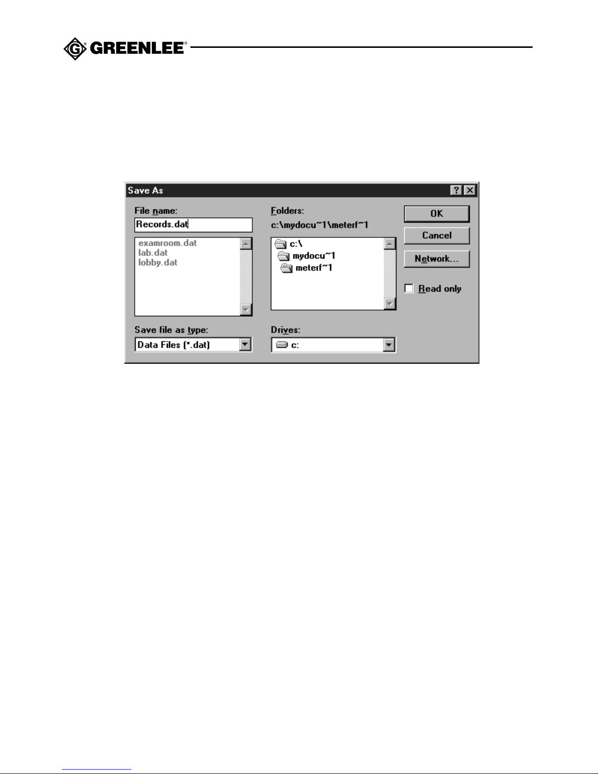
3. To save the data, on the list FILE menu, click SAVE. A Save As dialog box appears.
4. Enter a file name, using eight characters or less and add a .dat extension.
5. Click OK.
Erasing the recorded data
After you have downloaded and saved the data from the meter, you can erase it from the
meter. With the meter turned off, press and hold REC/ERASE while turning the meter on. “dEL”
will appear on the display to indicate that the data has been deleted.
Page 19
TML-30
19
Using Thermometer for Real-time Recording
Setting the Sampling Time for Real-time Recording
The TML-30 takes a reading every second. The sampling rate is the rate that those readings
are logged to the file. For example, even though the meter takes a reading every second, you
may decide to log a sample every 30 seconds. Setting the sample rate using the following
procedure sets the sample rate for real-time data and does not affect the sample rate in the
meter. The rate is set in seconds.
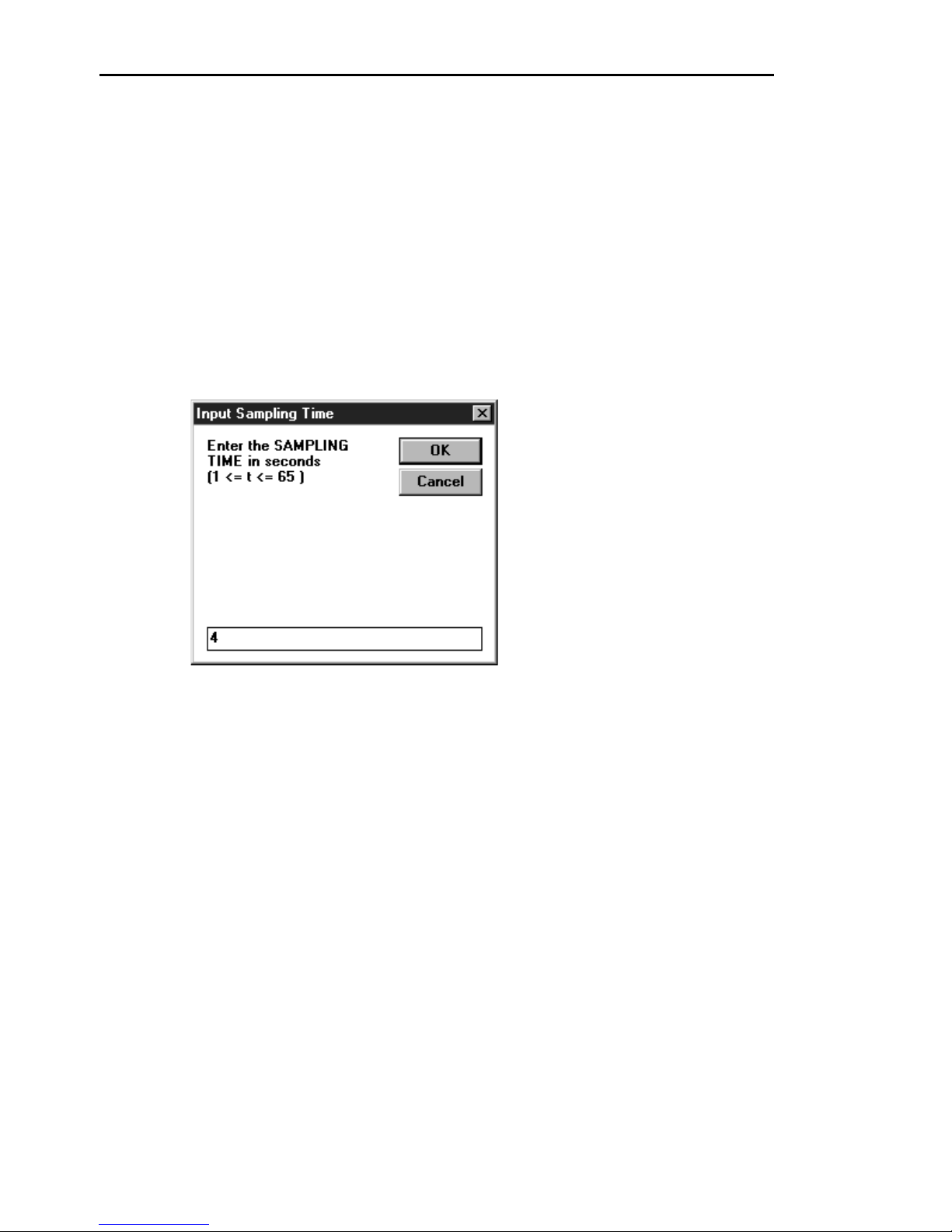
1. On the THERMOMETER dialog box DISPLAY menu, click SAMPLE RATE.
The Input Sampling Time dialog box appears.
2. Type in a new number. The maximum is 65 seconds.
3. Click OK. Data collected is sampled at the new rate.
Page 20

20
Recording Real-time data into the PC
Thermometer allows you to record readings directly into the PC from the meter without using
up memory in the meter. This is especially useful when you need more memory storage for
longer recording sessions. It also allows you to remotely monitor temperatures. When
recording from the PC, the buttons on the TML-30 continue to function normally; however the
word “Record” does not appear on the display. Before you begin, you must assign a file name.
1. Open a new file by clicking SAVE AS on the FILE menu. A Windows Save dialog box
opens.
2. Enter a file name, using eight characters or less and add a .dat extension.
3. Select a location for the file.
4. Click OK.
5. On the FILE menu, click START RECORDING. A message appears at the bottom of the
dialog box that shows the directory path and file name. The word “RECORDING” and the
record number appear below the file name. The “display” at the top of the dialog box
shows real-time data as it comes from the meter.
6. To quit recording data, on the FILE menu, click STOP RECORDING.
7. Click SAVE AS. The Save As dialog box appears.
8. Save the data under the same file name and location.
9. Click OK.
Using Thermometer for Real-time Recording (cont’d)
Page 21
TML-30
21
Using Saved Data
Data that has been saved to the PC can be opened in Thermometer or a spreadsheet
application such as Excel. If you prefer to open it in Thermometer, the meter must be
connected and turned ON.
Opening a File in Thermometer
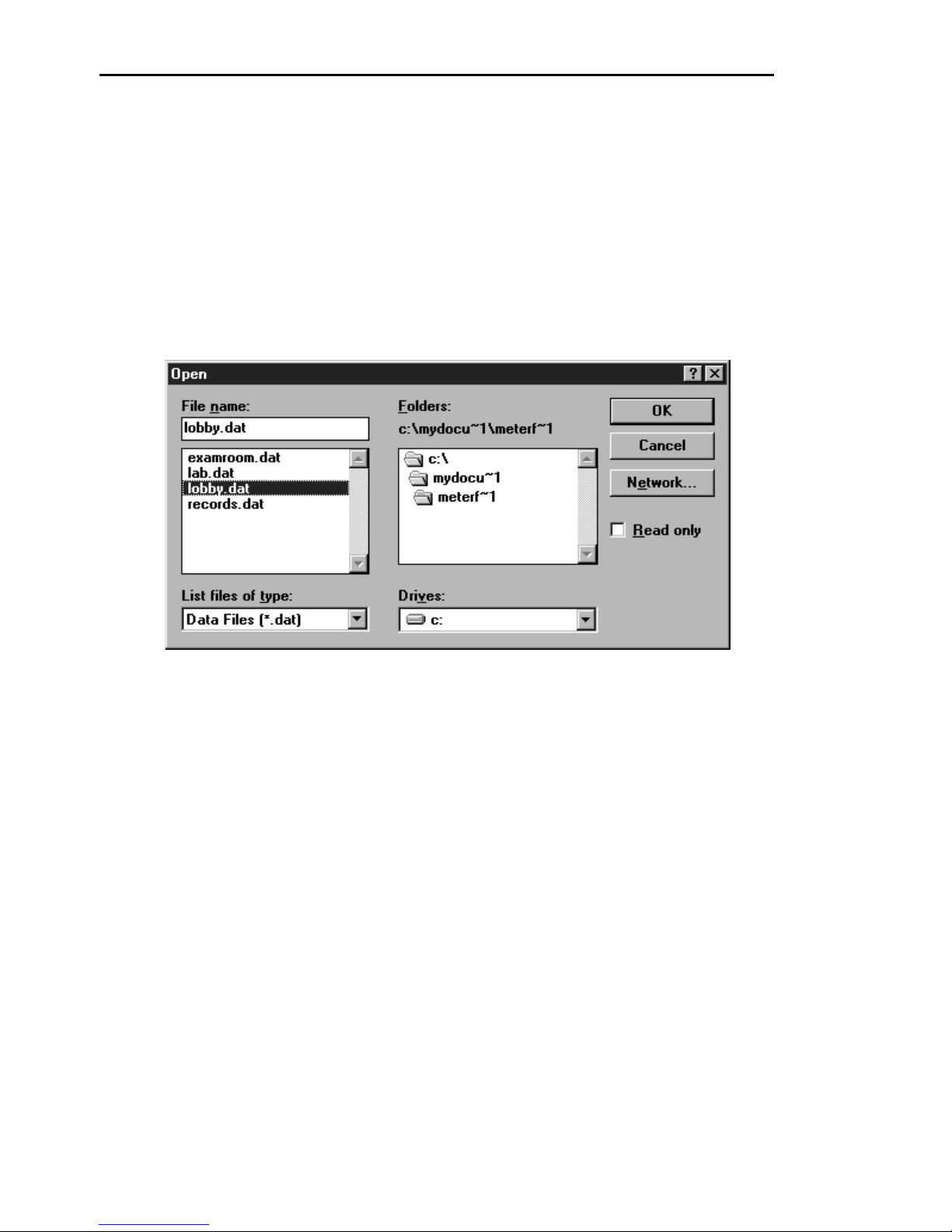
1. On the THERMOMETER dialog box FILE menu, click OPEN FILE. A Windows Open dialog
box appears.
2. Navigate to the file location and click the file name.
3. Click OK. The file opens in a list. See Using Lists.
Page 22
22
Importing a File into Excel
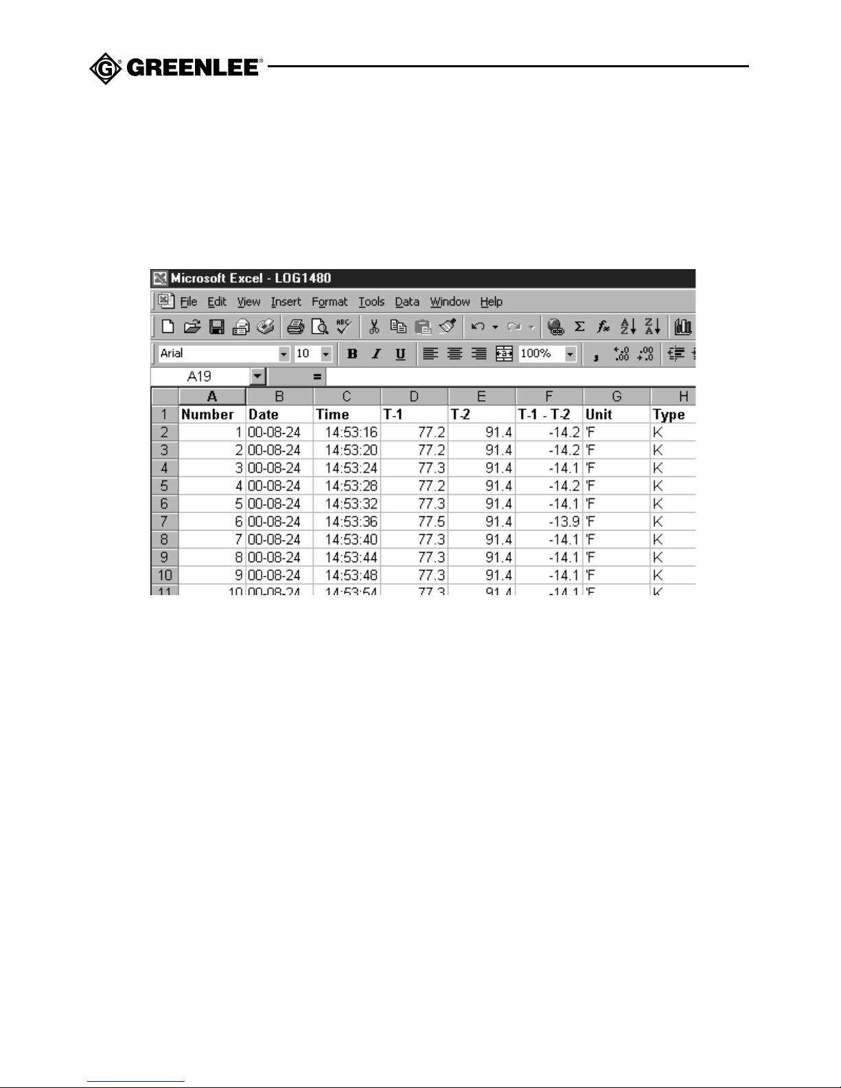
The data is stored as a .dat file and can be imported into any application, such as Excel, that
accepts a tab-delimited file. Refer to the program for the proper procedures for importing the
file. The illustration below shows an example of a file imported into Excel.
Page 23
TML-30
23
Accuracy
• See the Specifications section for operating conditions.
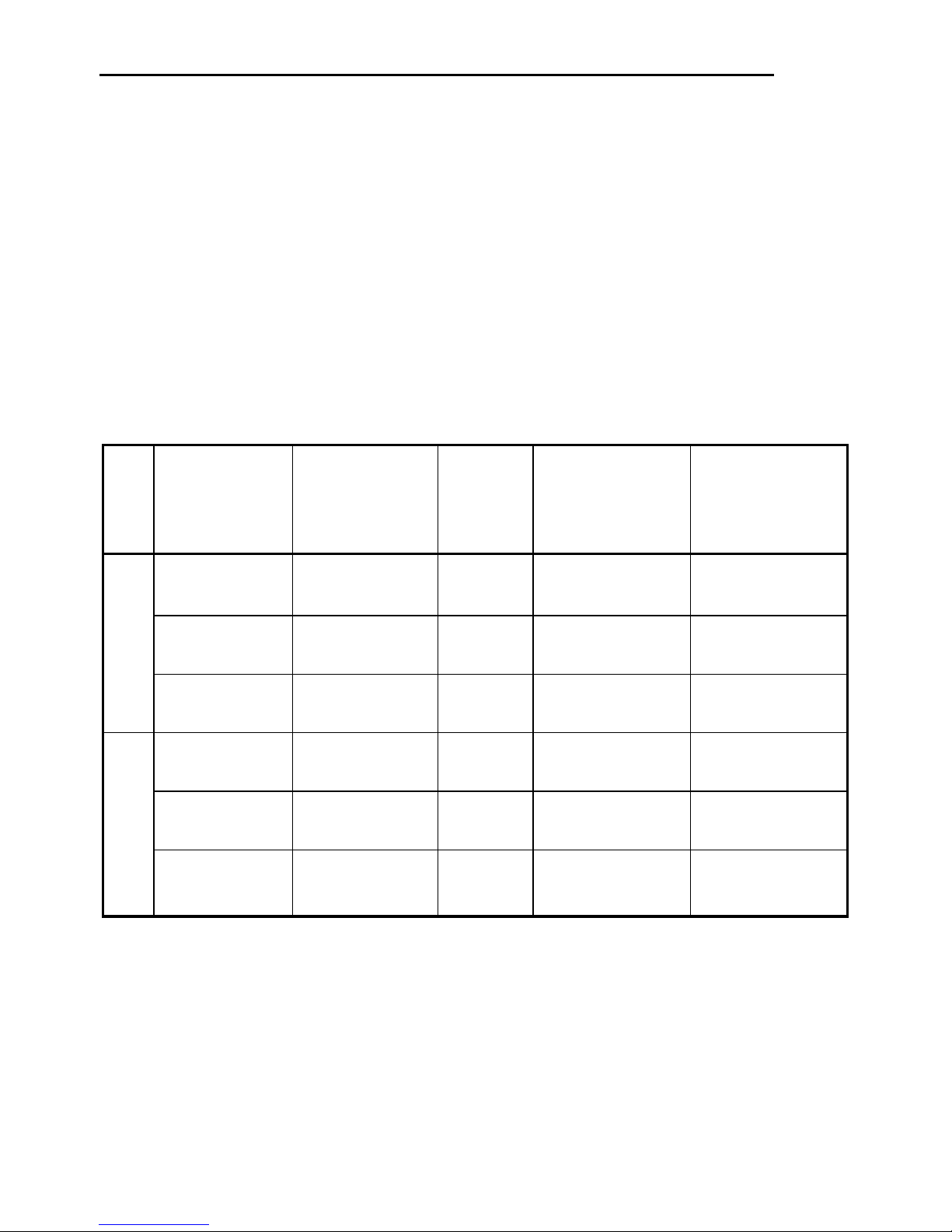
• Accuracy is specified as follows:
± (a percentage of the reading + a fixed amount) at 23 °C ± 5 °C (73.4 °F ±9 °F),
0% to 80% relative humidity.
• Temperature Coefficient (Nominal):
0.1 x (Specified Accuracy) per °C from 18 °C to 0 °C, and from 28 °C to 40 °C
0.056 x (Specified Accuracy) per °F from 64 °F to 32 °F, and from 82 °F to 104 °F
• The accuracy information is for the meter only; see the information sheet provided with
your temperature probe (purchased separately) for its accuracy.
°C
°F
-190 °C to 0 °C -190 °C to 0 °C 0.1 °C ± (0.5% of reading ± (0.7% of reading
+ 0.7 °C) + 0.7 °C)
0 °C to 999.9 °C0 °C to 760 °C 0.1 °C ± (0.1% of reading ± (0.3% of reading
+ 0.5 °C) + 0.5 °C)
1000 °C to 1333 °C — 1 °C ± (0.2% of reading ± (0.4% of reading
+ 1 °C) + 1 °C)
-310 °F to 0 °F -310 °F to 0 °F 0.1 °F ± (0.5% of reading ± (0.7% of reading
+ 1.4 °F) + 1.4 °F)
0 °F to 999.9 °F0 °F to 999.9 °F 0.1 °F ± (0.1% of reading ± (0.3% of reading
+ 1.0 °F) + 1.0 °F)
1000 °F to 2431 °F 1000 °F to 1400 °F1 °F ± (0.2% of reading ± (0.4% of reading
+ 2 °F) + 2 °F)
Scale K-Type J-Type Resolution Accuracy for Accuracy for
Thermocouple Thermocouple single thermocouple dual thermocouple
(T1 or T2) (T1 - T2)
measurements measurements
Page 24

24
Specifications
Display Type: LCD
Sampling Rate: 1 per second
Measurement Ranges
K-type Thermocouple: -190 °C to 1333 °C (-310 °F to 2431 °F)
J-type Thermocouple: -190 °C to 760 °C (-310 °F to 1400 °F)
Input Protection: 60 VDC or 24 VAC RMS
Data Storage: 8,000 dual-temperature readings in up to 255 data sets
Operating Conditions: 0 °C to 40 °C (32 °F to 104 °F), 10 to 80% relative humidity.
Indoor use only.
Storage Conditions: -10 °C to 60 °C (14 °F to 140 °F), 10 to 70% relative humidity.
Remove battery.
Elevation: 2000 meters (6500') maximum
Pollution Degree: 2
Power Source Battery: 9-Volt Battery (NEDA 1604, JIS 006P or IEC 6F22)
Memory Retention: One 3-volt lithium battery (NEDA 5004LC or IEC CR2032)
PC Requirements
IBM® compatible
486 processor or higher
4 MB RAM
3.5" floppy disk drive
4 MB hard drive space
EGA or higher monitor
Windows 95 or 98 operating system
Mouse
Serial port
COM settings:
Baud rate: 9600
Parity: None
Data bits: 8
Stop bit: 1
Page 25
TML-30
25
Maintenance
Replacing the Power Source Battery
1. Turn the meter off and disconnect thermocouples and RS-232 cable.
2. Remove the three screws from the back cover.
3. Remove the back cover.
4. Replace the battery (observe polarity).
5. Replace the cover and screws.
Replacing the Memory Retention Battery
1. Follow steps 1 through 3 above.
2. Press the retaining clip aside to remove the battery.
3. Replace the battery, observing polarity with + facing towards the back.
4. Replace the cover and screws.
Cleaning
Periodically wipe the case with a damp cloth and mild detergent; do not use abrasives or
solvents.
• Do not attempt to repair this unit. It contains no user-serviceable parts.
• Do not expose the unit to extremes in temperature or high humidity.
See Specifications.
Failure to observe these precautions can result in injury and can damage the unit.
Battery Replacement
Before opening the case, remove the accessories or thermocouples from the circuit
and shut off the unit.
Failure to observe this warning can result in severe injury or death.
Page 26

26
Page 27

TML-30
27
Page 28
For technical assistance: 800/435-0786
Greenlee Textron / Subsidiary of Textron Inc.
4455 Boeing Drive, Rockford, IL 61109-2988 USA
Technical / Customer Service (International): 815/397-7070 • Fax: 815/397-9247
Customer Service (North America): 800/435-0786 • Fax: 800/451-2632, 815/397-1865
Canada Fax: 800/524-2853
Lifetime Limited Warranty
Greenlee warrants to the original purchaser of these goods for use that these products will be free
from defects in workmanship and material for their useful life, excepting normal wear and abuse. This
warranty is subject to the same terms and conditions contained in Greenlee’s standard one-year
limited warranty.
For all Test Instrument repairs, ship units Freight Prepaid to:
Greenlee Textron, 4411 Boeing Drive, Rockford, IL 61109-2932 USA.
Mark all packages: Attention TEST INSTRUMENT REPAIR. For items not covered under warranty
(such as dropped, abused, etc.), repair cost quote available upon request.
Note: Prior to returning any test instrument, please check replaceable batteries or make sure the battery
is at full charge.
 Loading...