

Page 1
OPERATION, SERVICE AND PARTS
INSTRUCTION MANUAL
7904SB/7906SB
™
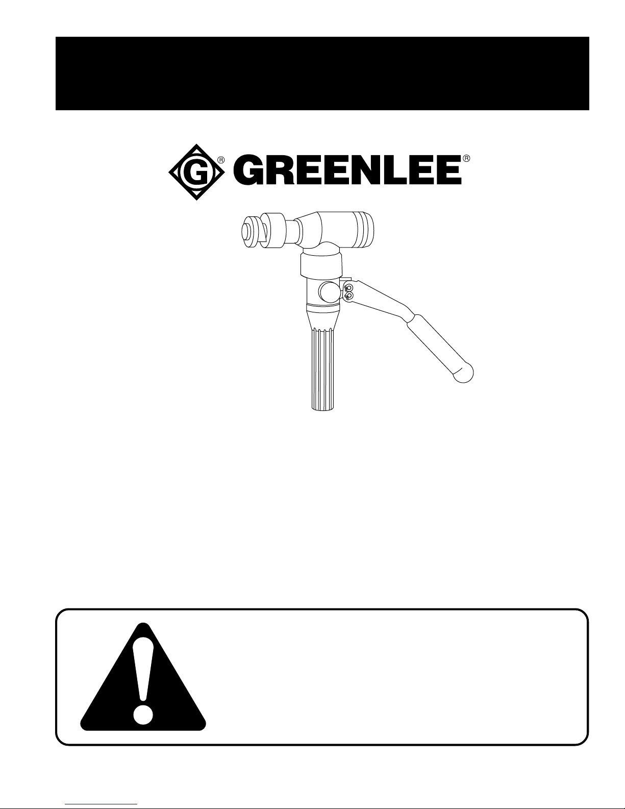
QUICK DRA W 90
HYDRAULIC PUNCH DRIVER
For units with serial code “WV”
Read and understand this material before operating
or servicing this equipment. Failure to understand how
to safely operate this tool could result in an accident
causing serious injury or death.
999 8832.1 © 1997 Greenlee Textron IM 1024 REV 6 7/97
Find Quality Products Online at: [email protected]
www.GlobalTestSupply.com
Page 2

Table of Contents
Description ............................................................................................................2
Important Safety Instructions............................................................................ 3-4
Specifications........................................................................................................5
Capacity And Draw Stud Selection Guide............................................................6
Operation .......................................................................................................... 7-9
Maintenance ................................................................................................. 10-12
Troubleshooting ............................................................................................ 13-14
Exploded View ....................................................................................................15
Parts List .............................................................................................................16
Draw Studs and Accessories..............................................................................17
7904SB/7906SB Hydraulic Punch Driver
Description
The Quick Draw 90™ is a self-contained hydraulic punch driver. The Quick
Draw 90™ and Greenlee punches, dies, and draw studs form a complete
system for punching holes of various shapes and sizes through mild steel,
aluminum, fiberglass and plastic. Slug-Splitter® punches, dies and studs are
available for punching all of these materials and stainless steel.
Various Quick Draw™ kits are available:
7904SB Quick Draw™ Hydraulic Punch Driver, draw studs
7906SB Quick Draw™ Hydraulic Punch Driver, draw studs, conduit-size punches and dies
7904E Quick Draw™ Hydraulic Punch Driver and draw studs
7904ESB Quick Draw™ Hydraulic Punch Driver, draw studs, Pg size punches and dies
7904ISO Quick Draw™ Hydraulic Punch Driver, draw studs, ISO size punches and dies
Greenlee Textron / Subsidiary of Textron Inc.
Find Quality Products Online at: [email protected]
www.GlobalTestSupply.com
2
4455 Boeing Dr., Rockford, IL 61109-2988 815/397-7070
Page 3
7904SB/7906SB Hydraulic Punch Driver
IMPORTANT SAFETY INSTRUCTIONS
SAFETY
ALERT
Immediate hazards which, if not avoided, WILL result in
severe personal injury or death.
SYMBOL
The symbol above is used to call your attention
to instructions concerning your personal safety.
Watch for this symbol. It points out important
safety precautions. It means Read the message
that follows and be alert to the possibility of
personal injury or death.
Safety is a critical factor in the design of Greenlee equipment. The best program starts with a safety-conscious
operator. The information highlighted in this bulletin describes operating practices for the benefit of the workers
who will use our equipment in their daily jobs. Comments from users are appreciated.
A person who has not read and does not understand all
operating instructions is not qualified to operate this tool.
Hazards or unsafe practices which, if not avoided, COULD
result in severe personal injury or death.
Hazards or unsafe practices which, if not avoided, COULD
result in minor personal injury or property damage.
Failure to read and understand safety instructions may
result in injury or death.
SA VE THESE INSTRUCTIONS
Additional copies of this manual are available upon request at no charge.
Greenlee Textron / Subsidiary of Textron Inc.
Find Quality Products Online at: [email protected]
www.GlobalTestSupply.com
3
4455 Boeing Dr., Rockford, IL 61109-2988 815/397-7070
Page 4
7904SB/7906SB Hydraulic Punch Driver
IMPORTANT SAFETY INSTRUCTIONS
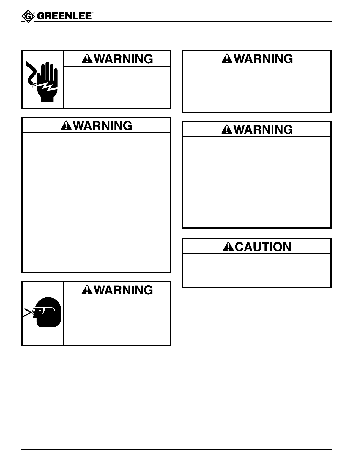
Electric shock hazard:
Do not use near live circuits.
Contact with live circuits can result
in severe injury or death.
• Do not exceed the rated capacity of the tool.
Exceeding the capacity of the tool could cause
tool or component to break and strike nearby
personnel.
• Do not add extensions or cheaters to the
handles. Using cheaters or applying more than
80 pounds (356 N) of handle force will damage
the driver and could propel internal parts with
great force, striking nearby personnel.
• Do not allow anyone to stand directly in front of
the punch. A component failure could propel the
punch and draw stud with great force, and could
strike nearby personnel.
• Use only Greenlee punches, dies, and draw
studs. Other punches, dies, and draw studs may
not withstand the force capacity of the driver and
could break, striking nearby personnel.
Do not operate the pump lever after the ram motion
stops. Continuing to operate the pump lever after
the ram motion stops will damage the driver and
could propel internal parts with great force, striking
nearby personnel.
• Inspect tool for wear or damage. Replace any
worn, damaged, or missing components with
Greenlee replacement parts. A damaged or
improperly assembled tool can break and strike
nearby personnel with sufficient force to cause
severe injury or death.
• Inspect the punch, die, draw stud and spacers
for wear or damage. Replace any worn or
damaged items with Greenlee replacement
parts. Replace any punches that have dull
cutting surfaces.
Use this tool for manufacturer’s intended use only.
Use other than that which is described in this
manual can result in injury or property damage.
Wear eye protection when
using this tool.
Failure to wear eye protection can
result in serious eye injury from
flying debris or hydraulic oil.
SA VE THESE INSTRUCTIONS
Additional copies of this manual are available upon request at no charge.
Greenlee Textron / Subsidiary of Textron Inc.
Find Quality Products Online at: [email protected]
www.GlobalTestSupply.com
4
4455 Boeing Dr., Rockford, IL 61109-2988 815/397-7070
Page 5

Specifications
Mechanical Data
Weight......................................................................................................... 7.4 lbs.
Overall Dimensions:
Maximum Handle Force............................................................................... 80 lbs.
Stroke (Maximum) .................................................... .850" Min. Draw Stud Travel
Maximum Rated Draw Stud Force ....................................................... 16,000 lbs.
Maximum Punch Diameter and Material Thickness ................ See Capacity Chart
Hydraulic Data
Max. Rated Operating Pressure ........................................................... 10,000 lbs.
Volume Operating Total (Cu. In.) .................................................................2.0735
Volume/Stroke (Cu. In./In.) .............................................................................0525
Circuit Capacity (Cu. In.) ....................................................................... Total: 3.50
7904SB/7906SB Hydraulic Punch Driver
Length.................................................................................................... 12.75"
Reservoir: 2.32
Seals ............................................... Nitrile, Fluorocarbon & Teflon Back-up Rings
Fluid Compatibility: Compatible with hydraulic oils, water, oil emulsions,
synthetic oils rated for use with nitrile (Buna N) and
fluorocarbon (Viton) seal material.
Circuit Type................................................................................................. Closed
Recommended Fluid.......................................................... Greenlee Hydraulic Oil
Miscellaneous
Operating Temperature...............................................10°F (-12°C) to 110°F (43°)
Operating Position .......................................................................... No restrictions
Greenlee Textron / Subsidiary of Textron Inc.
Find Quality Products Online at: [email protected]
www.GlobalTestSupply.com
5
4455 Boeing Dr., Rockford, IL 61109-2988 815/397-7070
Page 6
7904SB/7906SB Hydraulic Punch Driver
6
6
6
4
4
5
5
12345678901
1
1
1
1
1
1
1
1
12345678901
9
9
9
9
9
9
2
2
2
5
5
5
5
5
5
3
3
3
4
4
4
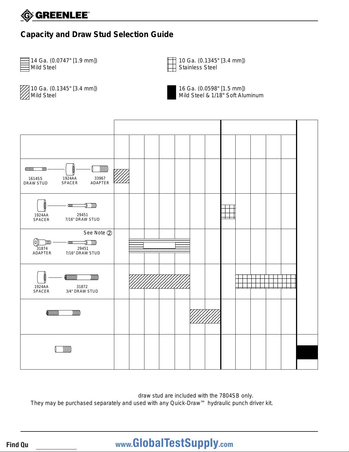
Capacity and Draw Stud Selection Guide
234
234
234
14 Ga. (0.0747" [1.9 mm])
234
234
234
Mild Steel
23
23
10 Ga. (0.1345" [3.4 mm])
23
Mild Steel
Stud and Accessories
1614SS
DRAW STUD
1924AA
SPACER
1924AA
SPACER
7/16" DRAW STUD
See Note
29451
33967
ADAPTER
2
2
10 Ga. (0.1345" [3.4 mm])
2
Stainless Steel
16 Ga. (0.0598" [1.5 mm])
Mild Steel & 1/18" Soft Aluminum
Standard & Slug-Buster® Punches
1/2"
3/4"
con.
ø 0.885"
15.2 mm
2345
2345
2345
1-7/32"
con.
ø 1.115"
28.3 mm
1"
con.
ø 1.362"
34.6 mm
1-1/4"
con.
ø 1.701"
43.2 mm
➁
1-1/2"
con.
ø 1.951"
49.6 mm
2"
con.
ø 2.416"
61.5 mm
1/2"
con.
ø 0.885"
15.2 mm
23
23
Slug-Splitters
3/4"
1-7/32"
con.
ø 1.115"
28.3 mm
ø 1.362"
34.6 mm
1"
con.
®
1-1/4"
con.
ø 1.701"
43.2 mm
31874
ADAPTER
1924AA
SPACER
29451
7/16" DRAW STUD
31872
3/4" DRAW STUD
31872
See Note
➁
234567890123456789012345678
234567890123456789012345678
234567890123456789012345678
234567890123456789012345678
See Note
234567890123456789012345678
234567890123456789012345678
23456789012345678901
23456789012345678901
23456789012345678901
➀
234567890
234567890
234567890
234567890
2345678901234
2345678901234
Electronic Connector Punches
3/4" DRAW STUD
33967
ADAPTER
➀ The Slug-Buster® punches may not split the slug when used with this adapter, because of the smaller pilot hole.
➁ The 31874 step-saver adapter and 29451 draw stud are included with the 7804SB only.
They may be purchased separately and used with any Quick-Draw™ hydraulic punch driver kit.
RS-232, 229, 231, 234, 238.
Greenlee Textron / Subsidiary of Textron Inc.
Find Quality Products Online at: [email protected]
www.GlobalTestSupply.com
6
4455 Boeing Dr., Rockford, IL 61109-2988 815/397-7070
Page 7
7904SB/7906SB Hydraulic Punch Driver
Operation
The 1/2" conduit-size punch is often used to increase
the size of the pilot hole; this is called “step-up punching”. After enlarging the pilot hole, the 3/4" draw stud is
used to punch the final hole. See steps 1-6.
1.
Drill 1/2" pilot hole using a Greenlee Kwik-Stepper
step bit.
2. Turn the release valve counterclockwise to make
sure the ram is fully extended. Install 3/8" draw
stud, 3/4" x 3/8" adapter, spacer and 1/2" conduit
die and insert into pilot hole.
®
4. Turn the release valve knob clockwise. Rotate
driver to best operating position, and then pump
lever handle until the punch is completely through
the material.
5. Release by turning release valve knob counterclockwise
and remove the punch, die, adapter and draw stud.
6.
3. Thread 1/2" conduit punch onto draw stud until the
punch is tight. Make sure the draw stud threads are
fully engaged in the punch.
Greenlee Textron / Subsidiary of Textron Inc.
Find Quality Products Online at: [email protected]
www.GlobalTestSupply.com
7
Install 3/4" draw stud and select proper size punch and
die for desired size hole and repeat steps 4 and 5.
4455 Boeing Dr., Rockford, IL 61109-2988 815/397-7070
Page 8
7904SB/7906SB Hydraulic Punch Driver
Operation (cont’d)
Using the 29451 draw stud and optional 31874 step-saver adapter
After drilling the pilot hole, use the 29451 draw stud
and 31874 step-saver adapter as shown here. These
components eliminate the need for step-up punching.
Note: The stud and adapter are rated to drive the
1-1/4" punch through 14 gauge mild steel .
Do not exceed the rated capacity of the 29451 draw
stud and 31874 step-saver adapter. Exceeding the
maximum rated capacity could cause the stud and
adapter to break and strike nearby personnel.
3. Thread 7/16" draw stud tightly into driver. Place the
die on the draw stud.
1. Drill 1/2" pilot hole using Greenlee Kwik-Stepper
step bit.
®
4. Turn the release valve knob counterclockwise, to
make sure the draw stud is fully extended. Insert
stud through pilot hole.
5. Thread the adapter with punch onto the draw stud.
2. Thread the adapter into the punch.
Greenlee Textron / Subsidiary of Textron Inc.
Find Quality Products Online at: [email protected]
www.GlobalTestSupply.com
8
4455 Boeing Dr., Rockford, IL 61109-2988 815/397-7070
Page 9
7904SB/7906SB Hydraulic Punch Driver
Operation (cont’d)
Using the 29451 draw stud and optional 31874 step-saver adapter (cont’d)
6. Make sure draw stud threads are fully engaged in
the adapter.
7. Turn release valve knob clockwise. Pump lever
handle until the punch is completely through the
material.
8. Release by turning the release valve knob counterclockwise.
9. Remove punch and die.
Greenlee Textron / Subsidiary of Textron Inc.
Find Quality Products Online at: [email protected]
www.GlobalTestSupply.com
9
4455 Boeing Dr., Rockford, IL 61109-2988 815/397-7070
Page 10

Maintenance
7904SB/7906SB Hydraulic Punch Driver
Maintenance and repairs should be performed in a dust
free area by qualified technicians.
This unit requires minimum maintenance because it
has a closed hydraulic system and all internal parts
are lubricated by the hydraulic fluid. Lubricate lever pins
lightly. Keep contaminants away from ram and housing.
Store with lever down and hydraulic pressure released.
Adding Hydraulic Oil
1. Place driver in vise in vertical position with handles
up. Unscrew reservoir handle (21) and remove
bladder plug (20). Open release valve knob (27) to
assure the ram is fully extended.
2. Fill bladder (29) to point of overflow with Greenlee
hydraulic oil.
3. Purge air from system:
Pump handle (22) several times to remove air from
the pumping chamber. Close release valve knob
and pump handle until ram (3) completes its full
travel. Repeat as necessary.
Note: Open release valve knob slowly so ram
extends slowly. Rapid return of oil and
air may cause oil to overflow the bladder.
If this procedure fails to remove air, remove bladder
plug and open release valve knob. Place thumb
over plug hole in bladder and squeeze bladder while
pumping handle several times. Close the release
valve knob and pump the handle until the ram
completes its full travel. Repeat as necessary.
If this procedure does not remove air, remove
plunger (24) and fill plunger cavity with clean oil
as outlined in Reassembly in the Maintenance
section of this manual.
4. Fill rubber bladder to the point of overflow and
replace bladder plug. Wipe bladder clean of excess
oil and reassemble reservoir handle.
Troubleshooting And Repair
To function properly, the punch driver must be free of oil
leaks, must build oil pressure, and the ram section (right
angle head) must rotate by hand force.
Oil Leaks
Check for external oil leaks.
Check that release valve knob and stem are closed
tightly and seating properly.
Remove reservoir handle (21) and check for oil leaks
around bladder (29) and bladder plug (20).
Failure to Build Pressure
Fill with oil and purge air from the system.
See Adding Hydraulic Oil.
Ram Section Will Not Rotate
Loosen and readjust set screw (13). Hold punch driver
with ram section up. Apply small amount of penetrating
oil to cylinder (1) at the attachment point, then work ram
section back and forth. Apply a small amount of SAE 30
oil to cylinder collar next to the pump block.
Rebuilding
If no leaks are visible and the unit will not build oil
pressure, disassemble and rebuild the punch driver.
Disassembly—Pump
Note:
Separate ram section from pump section.
Remove set screw (13). Unscrew ram
section from pump section.
1. Remove reservoir handle (21), and bladder plug
(20); drain oil from the bladder (29).
2. Remove O-ring (35) and the bladder (29). Remove
retaining rings (37) from one end of both handle
pins (30) and remove handle pins and handle (22).
3. Grasp plunger (24) with pliers; pull and twist to
remove. Loosen set screw (12) from release valve
knob (27); remove knob. Unscrew the release stem
(28) to remove from pump block (2).
4. Unscrew intake check seat (23); remove ball (32),
compression spring (31) and copper washer (40).
5. Unscrew the discharge check retainer (26). Remove
spring (39) and ball (5).
Disassembly—Ram
Note: See illustration on next page.
1. Loosen set screw (12). Unscrew spring retainer
(4) from ram housing (1). Remove compression
spring (7).
2. Screw a draw stud into end of ram (3); push the ram
out of the cylinder (1).
You have now disassembled the punch driver.
Thoroughly clean all parts and inspect the three
ball seats (intake, discharge and release stem)
for nicks, scratches, or other damage.
Greenlee Textron / Subsidiary of Textron Inc.
Find Quality Products Online at: [email protected]
www.GlobalTestSupply.com
10
4455 Boeing Dr., Rockford, IL 61109-2988 815/397-7070
Page 11
7904SB/7906SB Hydraulic Punch Driver
Flat Washer & Nut
Spring Retaining Plate (4)
Retaining Rings
Compression Spring (7)
Cylinder (1)
Installation
Rod
Ram (3)
Installation Rod (Steel)
#10-32 Thread
3
1
2
/
Maintenance (cont’d)
Ball Seat Repair Reassembly
Re-seating:
Minor seat imperfections may be corrected by
re-seating. Use a soft brass rod and hammer to
tap the ball against its seat.
Wear eye protection when
servicing this tool.
Failure to wear eye protection can
result in serious eye injury from
flying debris or hydraulic oil.
Re-drilling:
Badly worn or damaged seats may be reworked by
re-drilling and then re-seating.
The pump block is manufactured with seats of 118˚,
the standard drill point angle; use standard drills for
re-drilling.
•
To re-drill the 7/32" ball seat for release stem (28):
Use an “I” drill and a 9/64" diameter reamer.
• To re-drill the 7/32" ball seat for the discharge check:
Use an “I” drill and a 5/32" diameter reamer.
• To re-drill the 3/16" ball seat for the intake check: Use
a 1/4" drill and a 1/8" diameter reamer.
When drilling; remove a minimum of material to obtain
maximum seat life. Re-seat the balls before reassembly.
Reassembly is done in reverse sequence of disassembly.
Inspect all O-ring seals for cuts and wear; replace as
needed.
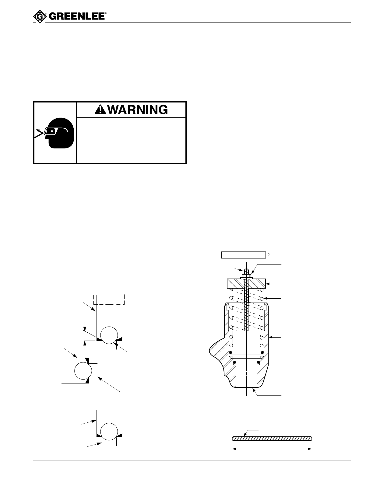
Reassembly—Ram Section
1. Lightly coat ram (3) and cylinder (1) seals, and both
bores of the cylinder with clean oil.
2. Push ram completely into cylinder.
3. Thread installation rod into tapped hole in the ram
and install compression spring (7). Place spring
retainer (4) on top of spring (7) so the installation
rod passes through the 1/4" hole in the spring
retainer.
4. Place a flat washer and thread a hex nut on the
installation rod. Tighten the nut until the spring
retainer threads contact the cylinder threads; screw
the spring retainer into the cylinder.
5. Remove the installation rod. Screw the spring
retainer approximately one thread below the surface
of the cylinder. Rotate the spring retainer (4) until
travel distance is .830" (21.1 mm) to .930" (23.6
mm). Tighten the set screw (12).
STD. DRILL
ACCEPTABLE
“I” DRILL
“I” DRILL
DISCHARGE
CHECK
5/32" REAM
RELEASE
VALVE
STEM
“B” DRILL
Greenlee Textron / Subsidiary of Textron Inc.
Find Quality Products Online at: [email protected]
9/64" REAM
9/64" REAM
INTAKE
CHECK
11
4455 Boeing Dr., Rockford, IL 61109-2988 815/397-7070
www.GlobalTestSupply.com
Page 12
Maintenance (cont’d)
7904SB/7906SB Hydraulic Punch Driver
Reassembly—Pump Section
Fill plunger (24) bore with clean hydraulic oil. Coat
O-ring seals on plunger with clean oil and reinsert
the pump block (2) with release valve knob (27) closed.
Reassembly—Ram to Pump
1. Apply clean hydraulic oil to the O-ring (14) groove
on the 1/2" diameter “stem” of the cylinder, and the
mating bore of pump block.
2. Apply a light coat of grease (Molycote G) to the
external threads of cylinder (1) and both ends of the
compression spring (41). Position the pump block
with the threaded end up and place the compression spring (41) into the pump block recess.
3. Insert the cylinder stem into mating bore of pump
block, compress the spring (41), and thread the
pump block onto the cylinder.
4. Apply Loctite 242 or equivalent to set screw (13)
and install until set screw bottoms. Back out the
set screw 1/8 to 1/4 turn.
5. Fill unit with clean oil and purge air. See Adding
Hydraulic Oil.
Inspection and Adjustments
After reassembly, check the following:
Ram Retracted
Measure ram travel distance (difference between
ram completely extended and completely retracted).
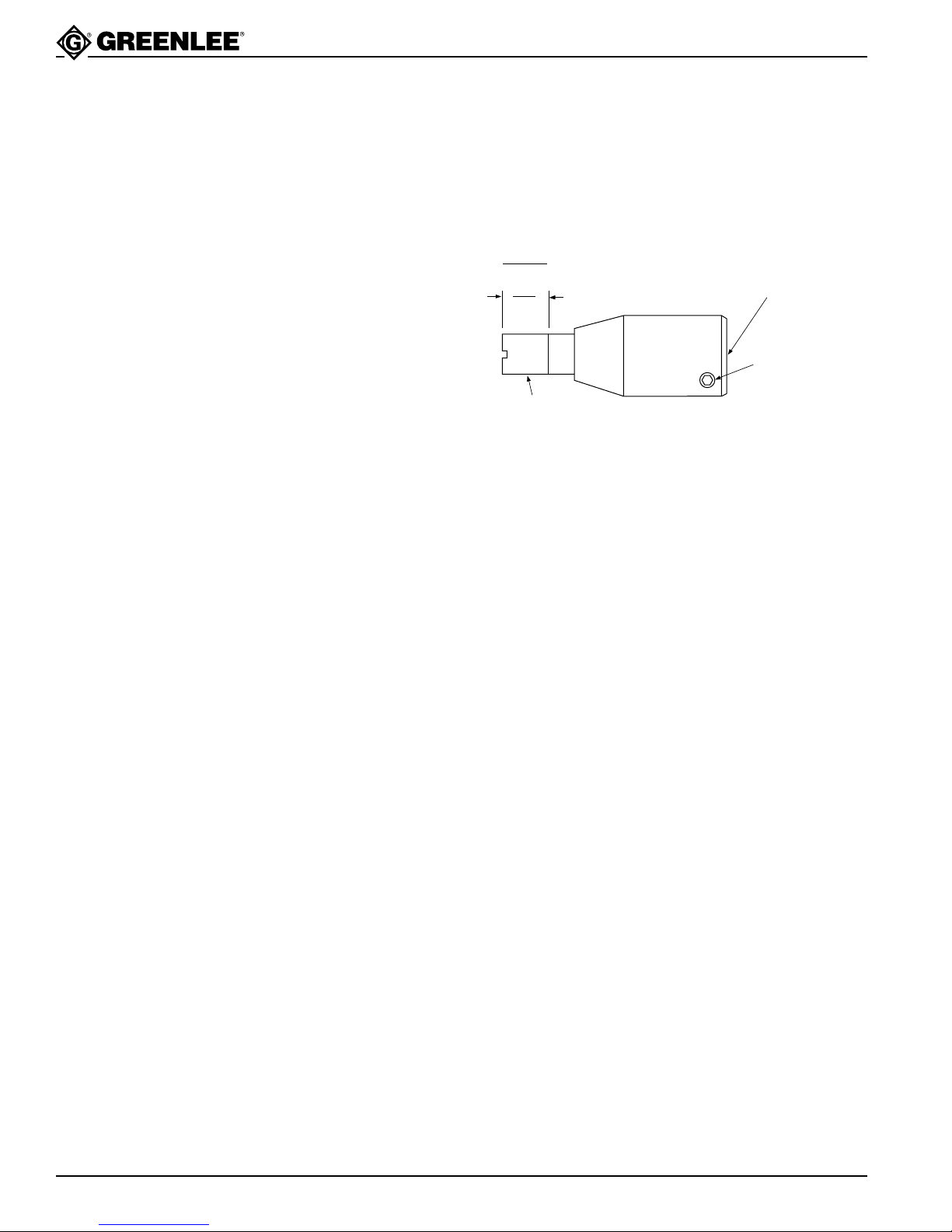
Rotate spring retainer (4) until travel distance is .830"
(21.1 mm) to .930" (23.6 mm). Tighten set screw (12).
(23.6 mm)
(21.1 mm)
.930"
.830"
33967
ADAPTER
RAM
TRAVEL
ROTATE SPRING RETAINER
TO MAKE ADJUSTMENT
SET SCREW
(12)
Pump Section Inspection
Intake Check Valve
Close the release valve knob and operate handle (22)
until ram (3) bottoms and handle resistance increases.
• If the ram bottoms in 30 strokes or less, the intake
check valve is operating properly.
•M
ore than 30 strokes indicates an intake check leak.
Re-seat, re-drill or replace the copper washer (40),
and compression spring (31).
Ram Travel Inspection
Ram Extended
With the draw stud removed and release valve knob
open, observe whether end of ram (3) is flush to 1/64"
(.396 mm) below the end of cylinder (1). If it is not, the
bladder (29) contains too much oil.
To remove excess oil:
1. Remove reservoir handle (21) and bladder plug
(20).
2. Slowly open release valve knob (27); excess oil
should come out of the bladder and the ram should
move to become flush to 1/64" (.396 mm) below the
end of the cylinder (1).
3 If excess oil does not come out, replace the
compression spring (7).
Discharge Check Valve
If the handle (22) returns to the raised position
by itself, the discharge check valve is leaking. Re-seat
or re-drill the discharge check seat and replace the
compression spring (39).
Release Valve
Pump the handle until the ram bottoms. Gently apply
and maintain additional force on handle (22). If the
handle remains solid, the ball (32) is operating properly.
If the handle (22) goes down slowly, the release valve is
leaking. Re-seat or re-drill the release stem seat and
replace O-ring (33).
Cylinder Rotation
Install a 3/4" draw stud and a 2" conduit size punch and
die to the punch driver. Hold the driver by the reservoir
handle (21) so the draw stud is horizontal; the cylinder
should not rotate from the combined weight of the draw
stud, the punch and the die. Replace compression
spring (31).
If binding or roughness occurs during cylinder rotation,
check for lubrication or damage at threads closest to set
screw (13); also check adjustment of set screw (13).
Greenlee Textron / Subsidiary of Textron Inc.
Find Quality Products Online at: [email protected]
www.GlobalTestSupply.com
12
4455 Boeing Dr., Rockford, IL 61109-2988 815/397-7070
Page 13
7904SB/7906SB Hydraulic Punch Driver
Troubleshooting
PROBLEM PROBABLE CAUSE POSSIBLE REMEDY
Will not punch hole. Improper assembly or use of punch, See Operating Instructions and
die or accessories. Capacity Chart.
Low oil level. See Adding Hydraulic Oil
in Maintenance Section.
Requires excessive lever force. Improper assembly or use of punch, See Operating Instructions and
die or accessories. Capacity Chart.
Material being punched is too thick or
too hard. See Capacity Chart.
Pump will not build pressure. Air in system. See step 3, Adding Hydraulic Oil.
Excessive number of strokes Inoperative intake check valve. See Inspection and Adjustments,
strokes are required to punch Intake Check Valve Inspection.
hole.
Inoperative discharge check valve. See Inspection and Adjustments,
Discharge Check V alve Inspection.
Leaking Release Valve. See Inspection and Adjustments,
Release Valve Inspection.
Damaged piston, piston extension, See Maintenance and Repairs, Cylinder
pump plunger seals or mating surfaces. and Pump Block sections.
Greenlee Textron / Subsidiary of Textron Inc.
Find Quality Products Online at: [email protected]
www.GlobalTestSupply.com
13
4455 Boeing Dr., Rockford, IL 61109-2988 815/397-7070
Page 14
7904SB/7906SB Hydraulic Punch Driver
Troubleshooting (cont’d)
PROBLEM PROBABLE CAUSE POSSIBLE REMEDY
Will not return piston. Weak or damaged return spring, See Piston Travel Inspection.
excess oil in unit.
External oil leaks. Damaged seals or surfaces. Damaged piston, piston extension,
pump plunger seals or mating surfaces.
See Troubleshooting and Repair,
Cylinder and Pump Block sections.
Damaged Release Valve Stem seal.
See Inspection and Adjustments,
Release Valve Inspection.
Greenlee Textron / Subsidiary of Textron Inc.
Find Quality Products Online at: [email protected]
www.GlobalTestSupply.com
14
4455 Boeing Dr., Rockford, IL 61109-2988 815/397-7070
Page 15
7904SB/7906SB Hydraulic Punch Driver
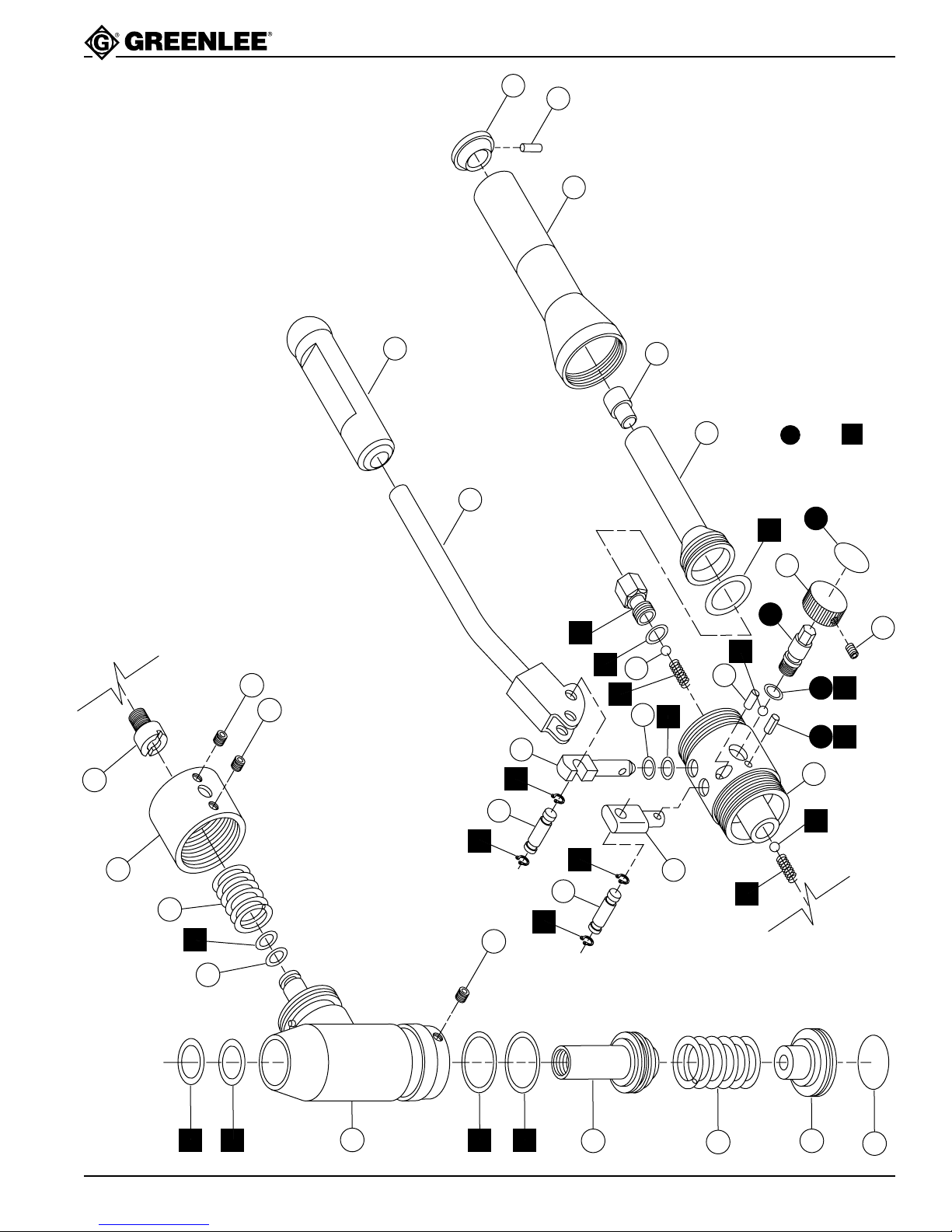
Exploded View
Serial Code WV
19
22
44
45
21
20
29
includes items keyed in black circles.
(16, 28, one of 33 and 34)
items keyed in black squares.
(6, 8-11 15, 23, 31, 33-35, 37, 39)
503 4296.7 Release Valve Unit Repair Kit
503 4297.5 Hydraulic Repair Kit includes
Repair Kits
35
16
26
27
28
23
40
32
43
13
24
37
30
37
5
30
41
15
12
14
37
37
31
36
33
37
6
38
33
34
2
6
39
12
33
34
15
9
10
3
4455 Boeing Dr., Rockford, IL 61109-2988 815/397-7070
7
4
17
8
11
Greenlee Textron / Subsidiary of Textron Inc.
Find Quality Products Online at: [email protected]
1
www.GlobalTestSupply.com
Page 16

Parts List
7904SB/7906SB Hydraulic Punch Driver
KEY PART NO. DESCRIPTION QTY.
1 503 5408.6 Cylinder, angle driver ............................................1
2 503 4273.8 Block, pump...........................................................1
3 503 3790.4 Ram, right angle driver..........................................1
4 503 3791.2 Retainer, spring .....................................................1
5 503 3792.0 Collar .....................................................................1
6 905 0292.2 Ball, steel, .218 diameter.......................................2
7 503 3907.9 Spring, compression, 1.34 x 1.65 x 1.76...............1
8 905 3847.1 Back-up ring, spiral, 1.00 x 1.24 x .027 Teflon .....1
9 905 1316.9 O-ring, 1.50 x 1.75 x .125 Nitrile ...........................1
10 905 3849.8 Back-up ring, spiral, 1.50 x 1.74 x .027 Teflon .....1
11 905 1330.4 O-ring, 1.00 x 1.25 x .125 Nitrile ...........................1
12 905 1032.1 Screw, set, #8–32 x .187 socket cup point ...........2
13 905 3771.8 Screw, set, 1/4–28 x .250 socket ..........................1
14 905 3850.1 Back-up ring, .375 ID ............................................1
15 905 0168.3 O-ring, .375 x .500 x .062......................................1
16 503 1878.0 Decal .....................................................................1
17 503 4301.7 Decal, identification ...............................................1
19 502 3258.4 Grip, .600 x 1.00 x 4.50.........................................1
20 503 2488.8 Plug, bladder .........................................................1
21 503 4281.9 Handle, reservoir...................................................1
22 503 4285.1 Handle, pump ........................................................1
23 503 4275.4 Seat, intake check.................................................1
24 503 4268.1 Plunger ..................................................................1
25 503 4274.6 Fulcrum post..........................................................1
26 503 4276.2 Retainer, discharge check.....................................1
27 503 4266.5 Knob, release valve...............................................1
28 503 4265.7 Stem, release ........................................................1
29 503 4269.0 Bladder ..................................................................1
30 503 4286.0 Pin, handle ............................................................2
31 503 4287.8 Spring, compression intake...................................1
32 905 0678.2 Ball, steel, .187 diameter.......................................2
33 905 3854.4 O-ring, .250 x .375 x .062......................................2
34 905 0458.5 Pin, roll, .125 x .375 ..............................................1
35 905 1456.4 O-ring, 1.12 x 1.31 x .093 Nitrile ...........................1
36 905 3853.6 Back-up ring, .250 ID ............................................1
37 905 3844.7 Retaining ring ........................................................4
38 905 3846.3 Pin, Drive-Lok, .25ø x 1.00....................................1
39 905 3845.5 Spring, compression, .152 x .180 x .380...............1
40 905 3852.8 Washer, copper .....................................................1
41 905 3869.2 Spring, compression .............................................1
43 905 0753.3 Screw, set 1/4–28 x .187 socket ...........................1
44 503 4278.9 Cap, reservoir handle............................................1
45 905 3855.2 Pin, drive, .125 diameter .......................................1
Greenlee Textron / Subsidiary of Textron Inc.
Find Quality Products Online at: [email protected]
www.GlobalTestSupply.com
16
4455 Boeing Dr., Rockford, IL 61109-2988 815/397-7070
Page 17

7904SB/7906SB Hydraulic Punch Driver
Draw Studs and Accessories
CATALOG NO. PART NO. DESCRIPTION QTY.
29451 502 9451.2 Draw stud, 7/16" stainless steel
31872 503 1872.1 Draw stud, 3/4–16 x 4.12 ........................1
31874 503 1874.8 Adapter, step-saver
1924AA 500 3248.8 Spacer, .767 x 1.37 x .875 ......................1
1614SS 503 0043.1 Screw, 3/8" short adapter ........................1
33967 503 3967.2 Adapter, stud, 3/8–24 x 3/4–16 ...............1
(optional)..................................................1
(optional)..................................................1
Greenlee Textron / Subsidiary of Textron Inc.
Find Quality Products Online at: [email protected]
www.GlobalTestSupply.com
17
4455 Boeing Dr., Rockford, IL 61109-2988 815/397-7070
 Loading...