

Page 1
INSTRUCTION MANUAL
Español ............................... 23
Français .............................. 45
Deutsch ............................... 67
Italiano ................................ 89
Service .............................. 111
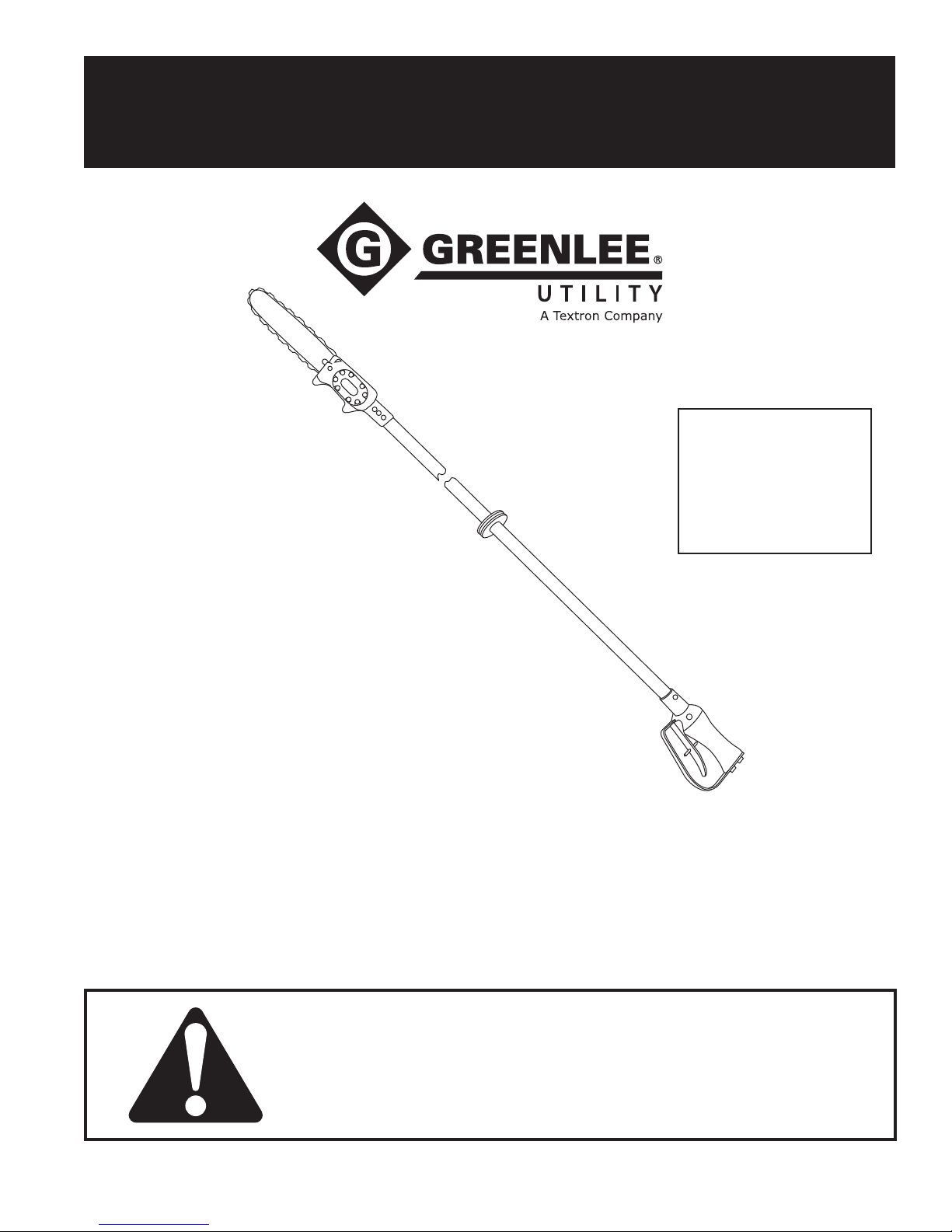
Long-Reach Chain Saws
Serial Codes AMT, AMS, GLZ, and GLY
Read and understand all of the instructions and
safety information in this manual before operating
or servicing this tool.
52020553 REV 7 © 2011 Greenlee Textron Inc. 2/11
Foam-filled
LRF 75 and 88
Register this product at www.greenlee.com
Page 2

Long-Reach Chain Saws (Foam-filled)
Table of Contents
Description ..................................................................... 2
Safety ............................................................................. 2
Purpose .......................................................................... 2
Other Publications .......................................................... 2
Important Safety Information ......................................3-6
Identication ................................................................... 7
Specications .............................................................. 8-9
Chain Saw Basics ...................................................10-12
Setting the Super Spool ............................................... 13
Hoses and Fittings ....................................................... 13
Hose Connections ........................................................ 13
Typical Setup ................................................................ 13
Operation ................................................................. 14-15
Maintenance ............................................................ 16-20
Troubleshooting ....................................................... 21-22
Español ......................................................................... 23
Français ........................................................................ 45
Deutsch ........................................................................ 67
Italiano .......................................................................... 89
Service
Disassembly .......................................................... 111
Assembly ........................................................112-113
Illustrations ..........................................................114-118
Parts List .............................................................119-120
Safety
Safety is essential in the use and maintenance of
Greenlee Utility tools and equipment. This instruction
manual and any markings on the tool provide information for avoiding hazards and unsafe practices related to
the use of this tool. Observe all of the safety information
provided.
Purpose
This manual is intended to familiarize all personnel
with the safe operation, specications and parts, and
maintenance procedures for the following Greenlee
Utility hydraulic tools:
52020556 LRF 75 Serial Codes AMT and GLZ
52020558 LRF 88 Serial Codes AMS and GLY
Keep this manual available to all personnel.
Replacement manuals are available upon request
at no charge.
Other Publications
Tool Owners/Users
SAE Standard J1273 (Hose and Hose Assemblies):
Publication 99930323
Description
Long-reach chain saws are hydraulically powered cutting
tools intended for general tree trimming from the ground
or from an aerial device.
Greenlee Utility’s patented Super Spool™ design allows
the tool to be used with either open-center or closed-
center hydraulic systems. The dielectric properties of the
berglass pole reduce the chance of electric shock when
the saw is used near energized electrical lines. Other
features include an anti-kickback chain, a fully covered
sprocket guard, a hand-stop safety collar, a trigger interlock and a trigger guard.
Super Spool is protected by U.S. Patent No. 4,548,229.
All specications are nominal and may change as design
improvements occur. Greenlee Textron Inc. shall not be liable for
damages resulting from misapplication or misuse of its products.
Super Spool is a trademark of Greenlee Textron Inc.
KEEP THIS MANUAL
Greenlee / A Textron Company 4455 Boeing Dr. • Rockford, IL 61109-2988 USA • 815-397-7070
2
Page 3
Long-Reach Chain Saws (Foam-filled)
IMPORTANT SAFETY INFORMATION
SAFETY
ALERT
SYMBOL
This symbol is used to call your attention to hazards
or unsafe practices which could result in an injury or
property damage. The signal word, dened below,
indicates the severity of the hazard. The message
after the signal word provides information for
preventing or avoiding the hazard.
Immediate hazards which, if not avoided, WILL result
in severe injury or death.
Hazards which, if not avoided, COULD result in
severe injury or death.
Hazards or unsafe practices which, if not avoided,
MAY result in injury or property damage.
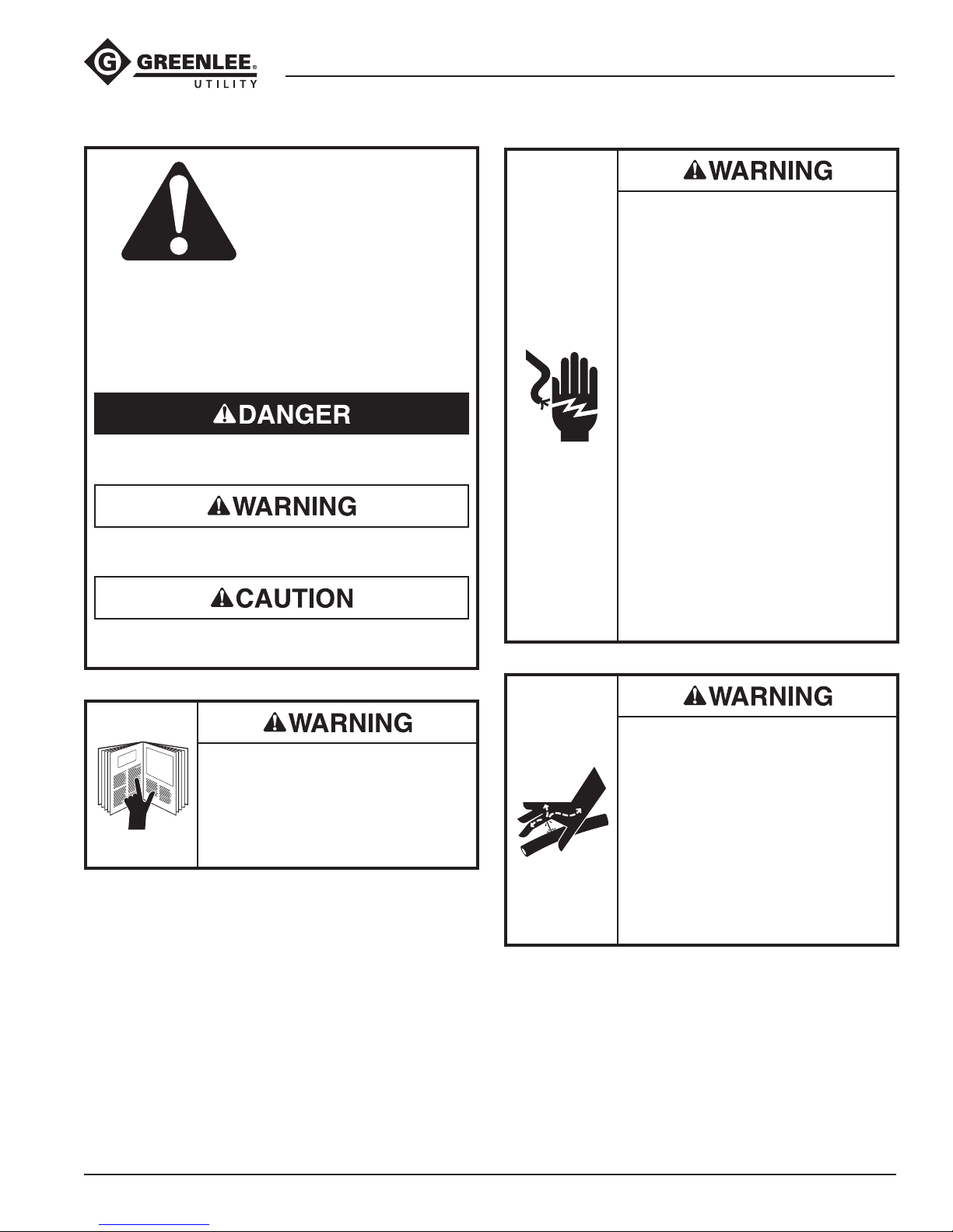
Electric shock hazard:
• This tool was tested to meet
OSHA 1910.269 (dry test) when
manufactured. It must be properly
cleaned and maintained to ensure
continued non-conductive properties. When using this unit near
energized electrical lines, use only
certied non-conductive hoses
and proper personal protective
equipment.
• Keep berglass extension clean
and dry when working around
energized electrical lines.
Accumulated oil or dirt reduces the
insulating properties of the tool.
• When using this tool near energized electrical lines, observe the
instructions provided in DIN EN
50110-1. The signicant sections
of this standard are provided in the
Operation section of this manual.
Failure to observe these warnings
could result in severe injury or death.
Read and understand all of the
instructions and safety information
in this manual before operating or
servicing this tool.
Failure to observe this warning could
result in severe injury or death.
Skin injection hazard:
• Do not use hands to check for leaks.
• Do not hold hose or couplers while
the hydraulic system is pressurized.
• Depressurize the hydraulic system
before servicing.
Oil under pressure easily punctures
skin causing serious injury, gangrene
or death. If you are injured by
escaping oil, seek medical attention
immediately.
Greenlee / A Textron Company 4455 Boeing Dr. • Rockford, IL 61109-2988 USA • 815-397-7070
3
Page 4
Long-Reach Chain Saws (Foam-filled)
IMPORTANT SAFETY INFORMATION
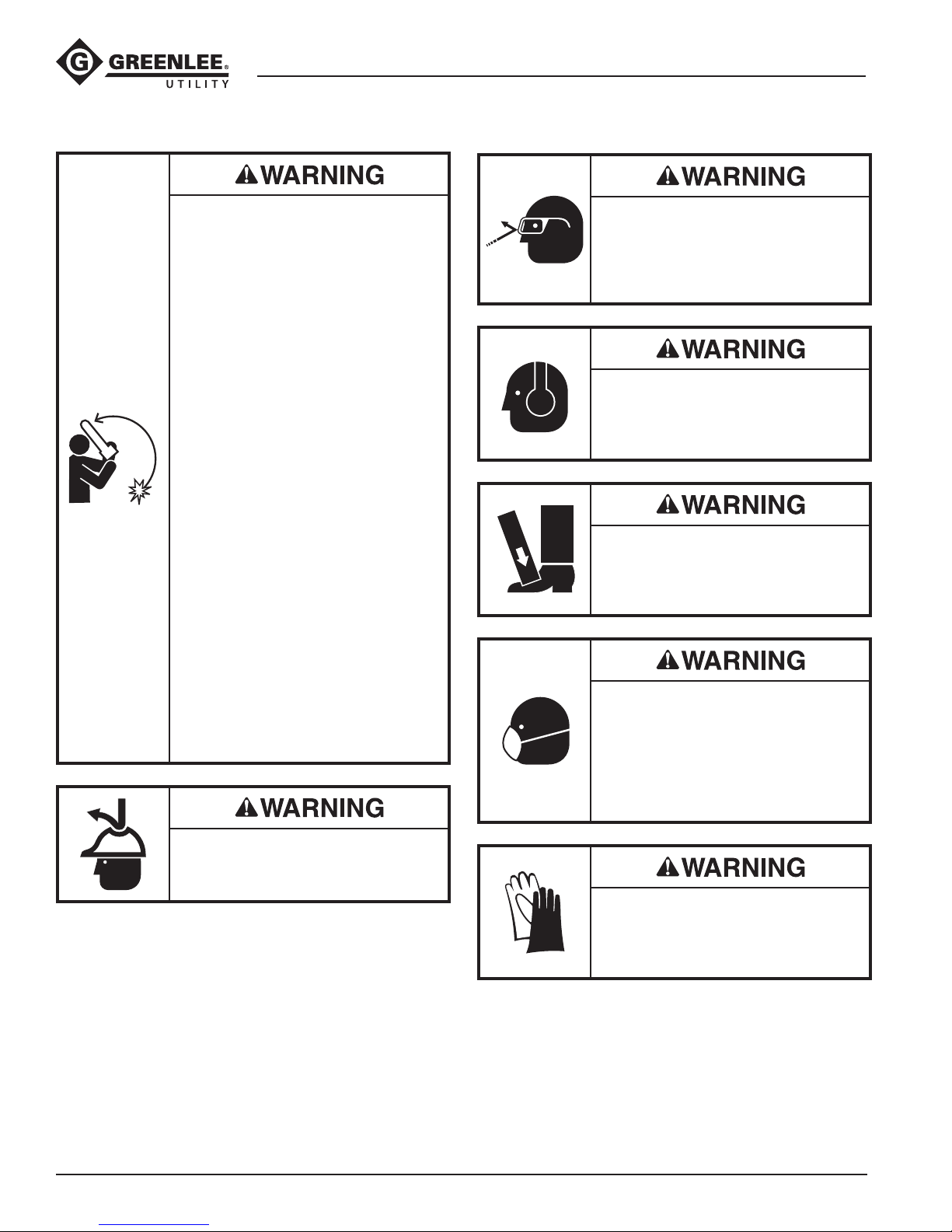
Before operating the saw, read and
understand the following explanations in this manual:
• Pull-In
Pull-in can occur when the blade
at the bottom of the bar contacts
a foreign object, such as a nail, or
when the blade is pinched in the
cut.
The saw will be suddenly and
forcefully pulled away from the
operator.
• Push-back
Push-back can occur when
the blade at the top of the bar
contacts a foreign object, such
as a nail, or when the blade is
pinched in the cut.
The saw will be suddenly and
forcefully pushed back toward the
operator.
• Kickback
Kickback can occur when the
chain at the guide bar tip contacts
anything. The bar of the saw will
travel upward and back, toward
the operator.
Failure to observe this warning could
result in severe injury or death.
Wear eye protection when operating
or servicing this tool.
Failure to wear eye protection could
result in serious eye injury from ying
debris or hydraulic oil.
Wear hearing protection when using
this tool.
Long-term exposure to high noise
levels could result in hearing loss.
Wear foot protection when using this
tool.
Failure to observe this warning could
result in serious injury.
Some types of timber can produce
hazardous dust when cut. Wear
a dust mask to prevent breathing
hazardous dust.
Failure to observe this warning could
result in temporary breathing difculty or serious injury.
Wear a hard hat when using this tool.
Failure to observe this warning could
result in severe injury or death.
Greenlee / A Textron Company 4455 Boeing Dr. • Rockford, IL 61109-2988 USA • 815-397-7070
Wear protective gloves when using
this tool.
Failure to observe this warning could
result in serious injury.
4
Page 5
Long-Reach Chain Saws (Foam-filled)
IMPORTANT SAFETY INFORMATION
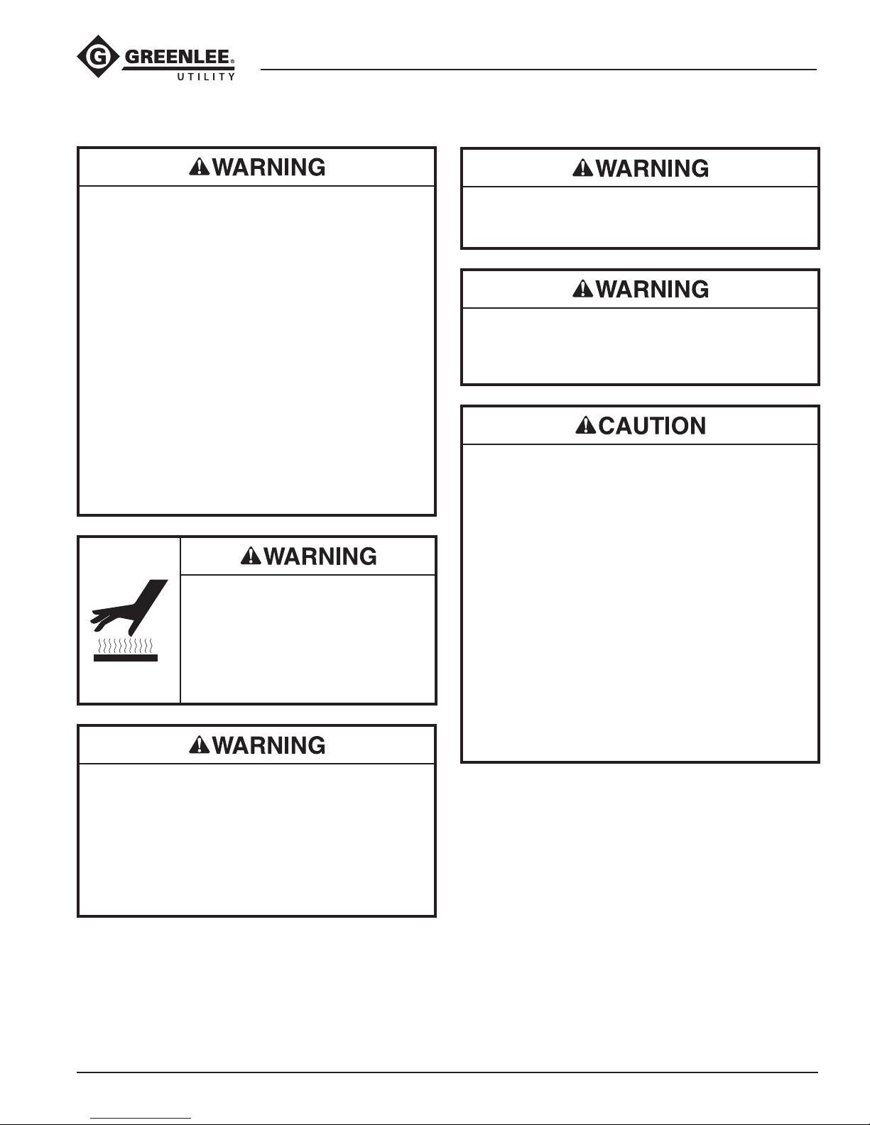
• Do not change accessories, inspect, adjust or
clean the tool or sharpen the chain when it is
connected to a power source. Accidental startup
could result in serious injury.
• Keep the handles clean, dry and free of hydraulic
uid.
• Maintain a rm grip on tool, using both hands with
thumbs and ngers encircling the handles at all
times. Serious injury could result if an operator
does not control the tool.
• Do not lock the trigger in the Power-ON position.
Operator cannot stop tool when trigger is locked.
• Do not remove or modify the tool’s safety trigger.
Accidental startup could result in serious injury.
• Wear protective gloves when handling or adjusting
the chain. The chain can cut even when stationary.
Failure to observe these warnings could result in
severe injury or death.
Saw body, bar, blade and other
components will be hot during and
after use. Use care when handling
the saw. Hot surfaces can cause
serious burns.
Failure to observe this warning could
result in severe injury or death.
Do not disconnect tool, hoses or ttings while the
power source is running or if the hydraulic uid is
hot. Hot hydraulic uid could cause serious burns.
Do not reverse hydraulic ow. Operation with
hydraulic ow reversed could cause tool malfunction. Connect the pressure hose and tank hose to the
proper ports.
• Use this tool for trimming or pruning trees only.
Any other use may result in injury or property
damage.
• Inspect tool before use. Replace any worn,
damaged or missing parts. A damaged or improperly assembled tool can malfunction, injuring
nearby personnel.
• Inspect hydraulic hoses and couplings every
operating day. Repair or replace if leakage, cracking, wear or damage is evident. Damaged hoses
or coupling could fail resulting in injury or property
damage.
• Ensure that all bystanders and unnecessary
personnel are clear of the work area when operating the tool. Nearby personnel may be injured by
falling debris.
Failure to observe these precautions may result in
injury or property damage.
To transport the chain saw:
• Allow the chain to stop rotating.
• Wait for the chain to cool.
• Use an appropriate guide bar sheath or scabbard.
• Carry the saw with the guide bar toward the rear.
Failure to observe these warnings could result in
severe injury or death.
Greenlee / A Textron Company 4455 Boeing Dr. • Rockford, IL 61109-2988 USA • 815-397-7070
5
Page 6
Long-Reach Chain Saws (Foam-filled)
IMPORTANT SAFETY INFORMATION
Hydraulic oil can cause skin irritation.
• Handle the tool and hoses with care to prevent
skin contact with hydraulic oil.
• In case of accidental skin contact with hydraulic
oil, wash the affected area immediately to remove
the oil.
Failure to observe these precautions may result in
injury.
Vibration hazard:
Apply just enough pressure to do the work. Applying
excess pressure to the tool can cause operator
discomfort or temporary numbness.
Failure to observe this precaution may result in injury.
• Check the operation of the automatic oiler
frequently. See Checking and Setting the
Automatic Chain Oiler in this manual.
• Check the chain frequently for proper tension and
sharpness. Tension and sharpen as necessary.
See the instructions under Saw Chain and Bar
Maintenance.
• Check the uid level of the power source reservoir
frequently. The automatic oiler uses hydraulic uid
to lubricate the bar and chain, and will cause the
uid level to drop.
Procedure for disconnecting hydraulic hoses, ttings
or components:
1. Move the ow lever on the hydraulic power
source to the OFF position.
2. Stop the power source.
3. Follow the sequence under Disconnecting Hoses
to prevent pressure buildup. In case some
pressure has built up, loosen hoses, ttings or
components slowly.
Emergency stop procedure:
1. Release the trigger.
2. Shut off the hydraulic power source.
Note: Keep decals clean and legible. Replace decals
when necessary.
Greenlee / A Textron Company 4455 Boeing Dr. • Rockford, IL 61109-2988 USA • 815-397-7070
6
Page 7
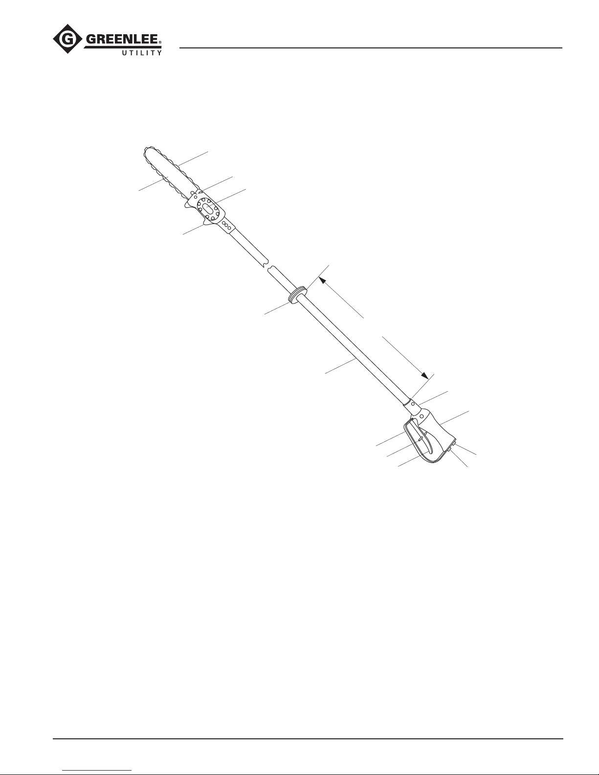
Identification
14
Long-Reach Chain Saws (Foam-filled)
1
2
3
13
12
889 mm (35")
Long-Reach Chain Saws
1. Saw Chain
2. Automatic Oiler
3. Hydraulic Gear Motor
4. Serial Number
5. Handle
6. Return Port
7. Pressure Port
11
10
9
8
8. Trigger
9. Trigger Interlock Latch
10. Trigger Guard or Trigger Strap
11. Tube Assembly, Foam-lled
12. Hand Stop
13. Saw Head
14. Guide Bar
4
5
6
7
Greenlee / A Textron Company 4455 Boeing Dr. • Rockford, IL 61109-2988 USA • 815-397-7070
7
Page 8
Specifications
Long-Reach Chain Saws (Foam-filled)
Long-Reach Chain Saw
Type of Hydraulic System .............................Open-center
or closed-center
Hydraulic Ports
Pressure ...............................9/16–18 SAE O-ring Boss
Return.....................................3/4–16 SAE O-ring Boss
Cutting Capacity ......................................... 330 mm (13")
Chain Speed @ 30 l/min (8 gpm) ................... 1280 m/min
(4200 ft/min)
Sound Power Level ............................................ 106 Lwa
Vibration ............................................................4.88 m/s
Mass/Weight
52020556 ............................................4.06 kg (9.03 lb)
52020558 ............................................4.21 kg (9.36 lb)
Length
52020556 ........................................... 1890 mm (74.5")
52020558 ........................................... 2200 mm (86.5")
Width (at motor) ....................................... 108 mm (4.25")
Depth of Body (at handle) ............................ 152 mm (6")
Saw Chain
When replacement is necessary, select a saw chain that:
• meets applicable industrial safety code specications
• is rated for 1280 m/min (4200 ft/min)
Failure to observe this warning could result in severe
injury or death.
2
Pitch ..................................................... 8.26 mm (0.325")
Gauge ................................................... 1.47 mm (0.058")
Greenlee / A Textron Company 4455 Boeing Dr. • Rockford, IL 61109-2988 USA • 815-397-7070
8
Page 9
Specifications (cont’d)
Long-Reach Chain Saws (Foam-filled)
Hydraulic Power Source
Do not exceed the following hydraulic power source
maximums:
• Hydraulic ow: 30.3 l/min (8 gpm)
• Pressure relief setting: 138 bar (2000 psi)
• Back pressure: 13.8 bar (200 psi)
Failure to observe this warning could result in severe
injury or death.
Type of Hydraulic System ..... Open-center or closed-center
Flow
Minimum ..........................................18.9 l/min (5 gpm)
Recommended ................................. 22.7 l/min (6 gpm)
Maximum .........................................30.3 l/min (8 gpm)
Filtration ............................................ 10 micron (nominal)
Pressure Relief Setting ........................138 bar (2000 psi)
Back Pressure (maximum)* ..................13.8 bar (200 psi)
*
13.8 bar (200 psi) is the maximum agreed standard
back
pressure for the HTMA (Hydraulic Tool Manufacturers
Association). Greenlee Utility tool will operate satisfac-
torily at this standard.
1. Maximum hydraulic uid temperature must not
exceed 60 °C (140 °F). A sufcient oil cooling
capacity is needed to limit the hydraulic uid
temperature.
2. Hydraulic ow must not exceed 30.3 l/min (8 gpm).
Install a ow meter in the return line to measure the
rate of hydraulic ow before using the tool.
3. Pressure relief valve setting must not exceed 138
bar (2000 psi) at your tool’s maximum ow. Locate
the pressure relief valve in the supply circuit to limit
excessive hydraulic pressure to the tool.
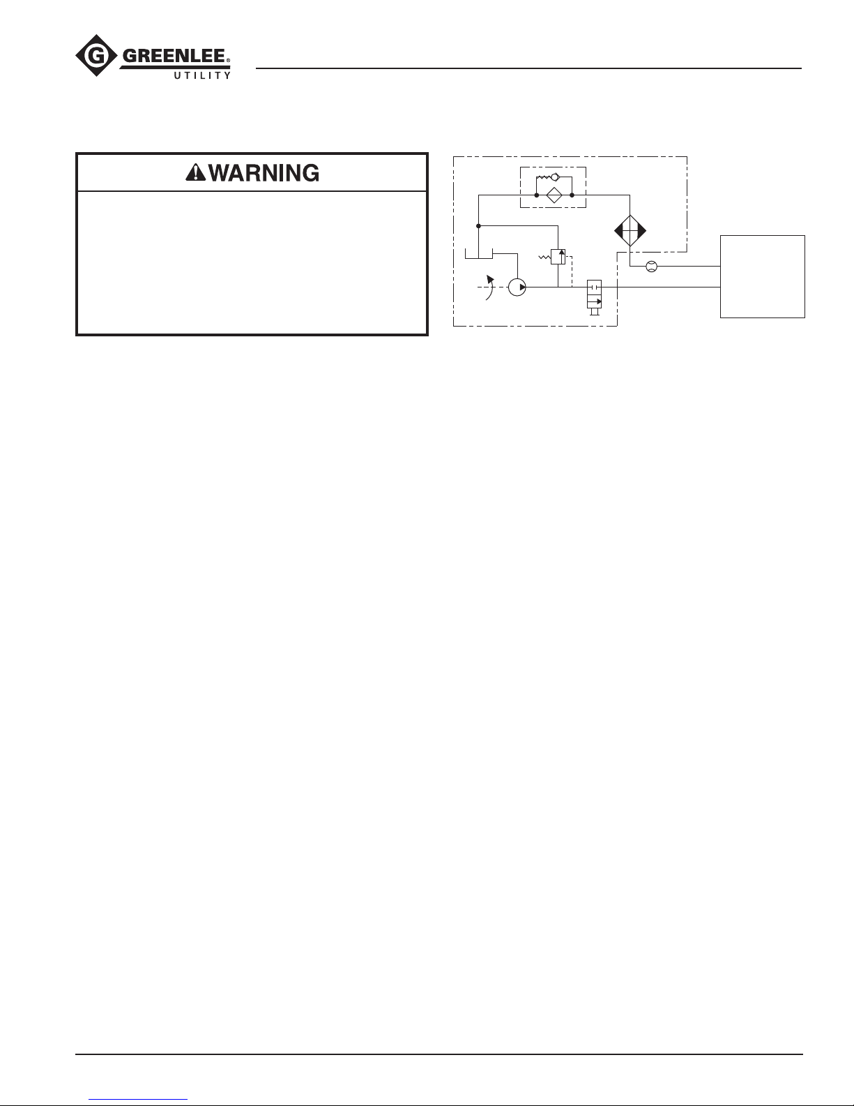
Hydraulic Schematic
FILTER
(10 micron)
RESERVOIR
PUMP
POWER SOURCE
RELIEF
VALVE
138 bar
(2000 psi)
CONTROL
VALVE
COOLER
FLOW METER
T
P
TOOL
Recommended Hydraulic Fluids
Use any non-detergent, petroleum-based hydraulic
uid which meets the following specications or HTMA
specications.
S.U.S. @:
38 °C (100 °F) ...............................................140 to 225
99 °C (210 °F) ............................................ 40 minimum
Flash Point ................................170 °C (340 °F) minimum
Pour Point .................................. -34 °C (-30 °F) minimum
Greenlee / A Textron Company 4455 Boeing Dr. • Rockford, IL 61109-2988 USA • 815-397-7070
9
Page 10
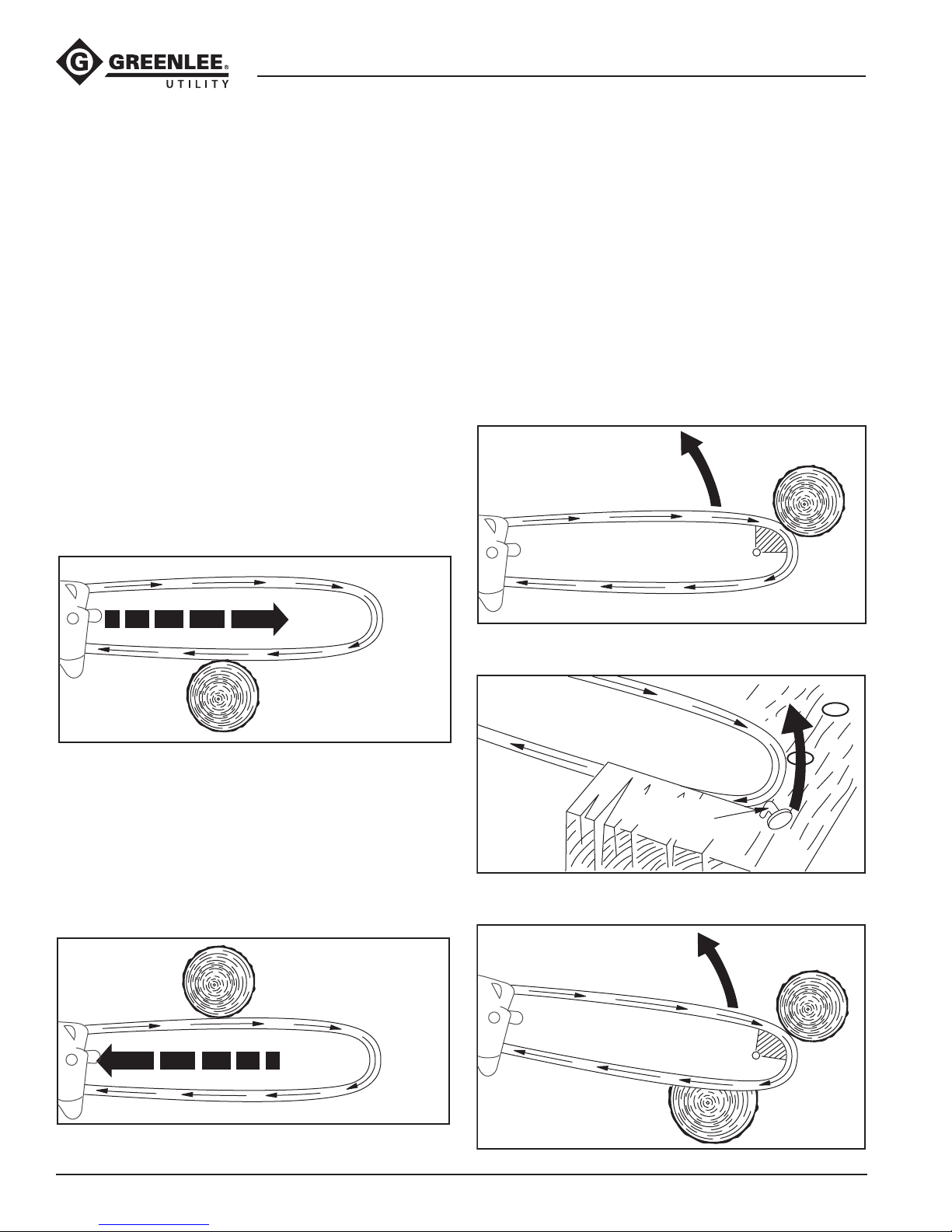
Chain Saw Basics
Long-Reach Chain Saws (Foam-filled)
This section introduces some basic principles of chain
saw use: Hazard Prevention, Compression and Tension.
HAZARD PREVENTION
The cutting action of this chain saw is performed by a
chain-type blade driven at high speed by a powerful
hydraulic motor. When used carefully and properly, the
chain saw is a highly effective cutting tool.
When used improperly, or when anything interferes with
the normal rotation of the blade, the operator could
very suddenly and very quickly lose control of the saw.
Such loss of control can result in harm to the operator.
The three terms that describe loss of control are pull-in,
push-back, and kickback.
Pull-In
Pull-in can occur when the blade at the bottom of the
bar is doing the cutting. If the blade is suddenly pinched
in the cut, or if it contacts a foreign object such as a
nail, the saw may be suddenly and forcefully pulled
away from the operator.
Pull-In
Kickback
Kickback is much more hazardous than pull-in or pushback. When kickback happens, the entire saw may
rotate suddenly and forcefully. The bar of the saw may
quickly travel upward and back, toward the operator.
Kickback can occur when the blade at the guide bar
tip contacts anything while the chain is rotating. Some
causes for kickback are:
• using the guide bar tip for cutting.
• contacting a nail or other metal object when cutting.
• accidental contact when cutting more than one
branch at a time.
Using Guide Bar Tip for Cutting
PULL
Push-Back
Push-back can occur when the blade at the top of the
bar is doing the cutting. If the blade is suddenly pinched
in the cut, or if it contacts a foreign object such as a
nail, the saw will be suddenly and forcefully pushed
back toward the operator.
Push-Back
PUSH
Contact with Metal Objects
Metal
Objects
Cutting More Than One Branch at a Time
Greenlee / A Textron Company 4455 Boeing Dr. • Rockford, IL 61109-2988 USA • 815-397-7070
10
Page 11
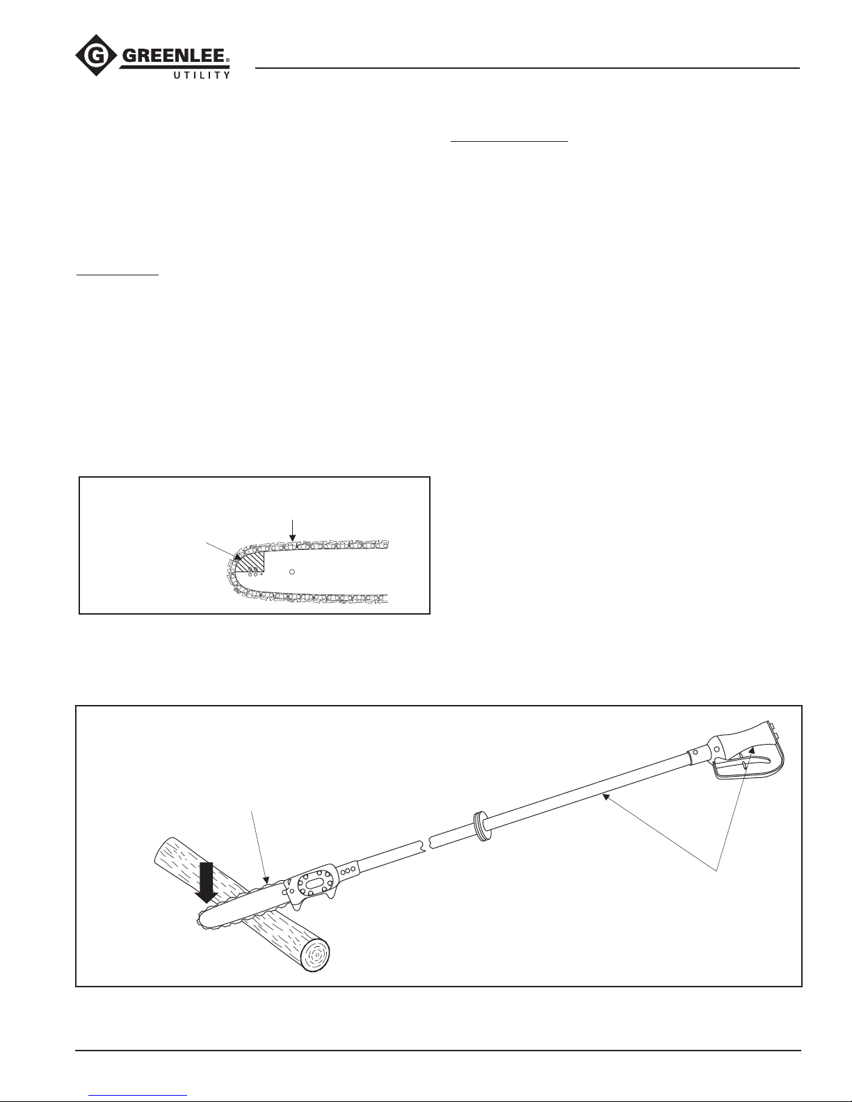
Chain Saw Basics (cont’d)
Long-Reach Chain Saws (Foam-filled)
Preventing Pull-In, Push-Back and Kickback
The chain/bar combination and shroud are intended to
prevent or reduce the likelihood and severity of kickback. Verify that these items are in good working order
(chain is sharp and properly tensioned, shroud is not
damaged, etc.) to get the maximum benet from these
features. If worn or damaged, replace these items with
Greenlee Utility replacement parts.
General Tips:
• Maintain the saw properly. Verify that the blade is
sharp and has been properly tensioned.
• Do not allow the guide bar tip to contact anything.
• Do not over-reach.
• Do not use the saw above shoulder height.
• Cut only one limb, branch, or log at a time.
• Be aware that small-diameter limbs or branches are
more likely to catch the blade, causing pull-in or
kickback.
Verify that the chain is sharp
and properly tensioned.
Do not allow the
guide bar tip to
contact anything.
Cutting Procedure:
• Hold the chain saw securely with both hands and
maintain a rm, secure grip.
• Bring the chain saw to full rpm before starting the cut.
Maintain full rpm until the cut is completely nished.
• Apply a moderate amount of downward force to the
saw.
• Cut straight through. Do not twist the saw during
the cut.
• Be alert for the limb to shift, which may pinch the saw
in the cut.
• Be alert for a limb or branch under tension to spring
back when the cut is complete and the tension is
released.
Cutting Procedure
Bring chain to full rpm.
Maintain full rpm until
the cut is finished.
Hold saw securely
Apply a moderate
amount of
downward force.
Greenlee / A Textron Company 4455 Boeing Dr. • Rockford, IL 61109-2988 USA • 815-397-7070
11
with both hands.
Page 12
Long-Reach Chain Saws (Foam-filled)
Chain Saw Basics (cont’d)
Site Preparation Tips
• Prepare the cutting area by clearing away brush,
branches, vines, etc.
• Remove any unnecessary tools and coil up excess
hydraulic hose.
• Survey the limb or branch to predict the direction or
path of fall. Ensure that no personnel are in that area.
• If working in a municipal area, plan the direction of
fall so that a limb doesn’t fall into a roadway, strike a
nearby building, contact nearby power lines, etc.
• If the tree is on an incline, work uphill from the fall
path. A branch might tend to bounce or roll downhill.
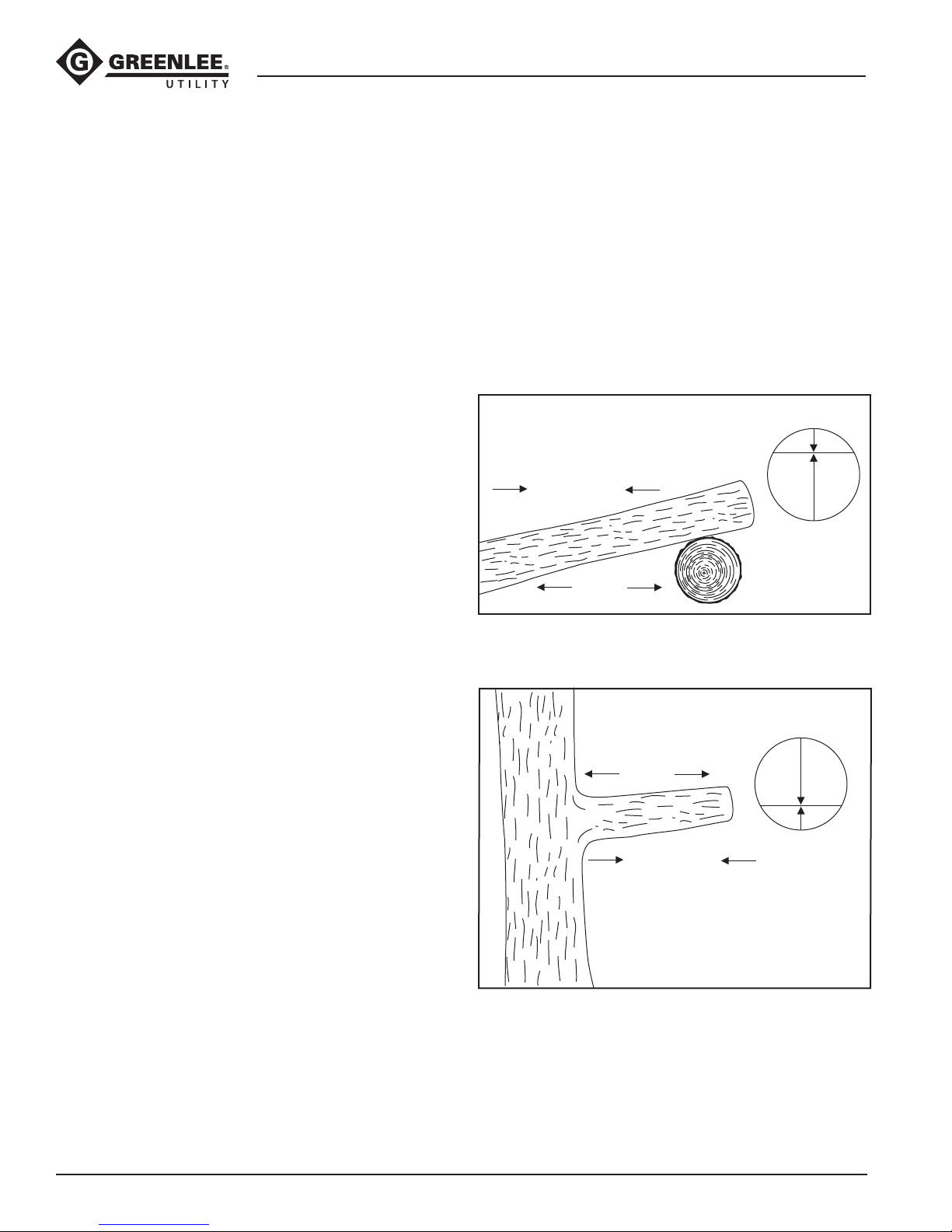
COMPRESSION AND TENSION
Any branch or log will have two forces acting on it—
compression and tension. As the branch or log is cut,
compression tends to push the two halves toward each
other. Tension tends to pull the two halves apart.
See the illustrations. A log or limb supported at both
ends has the compression on the top. A log or limb
supported at one end has the compression on the
bottom.
Make the rst cut on the compression side. Cut through
approximately 1/3 of the log’s diameter. Make the
second cut on the tension side. This will decrease the
likelihood that the saw will become pinched in the cut.
Compression on Top
Side View
1
Compression
2
Tension
Compression on Bottom
Tension
Compression
Side View
2
1
Greenlee / A Textron Company 4455 Boeing Dr. • Rockford, IL 61109-2988 USA • 815-397-7070
12
Page 13
Long-Reach Chain Saws (Foam-filled)
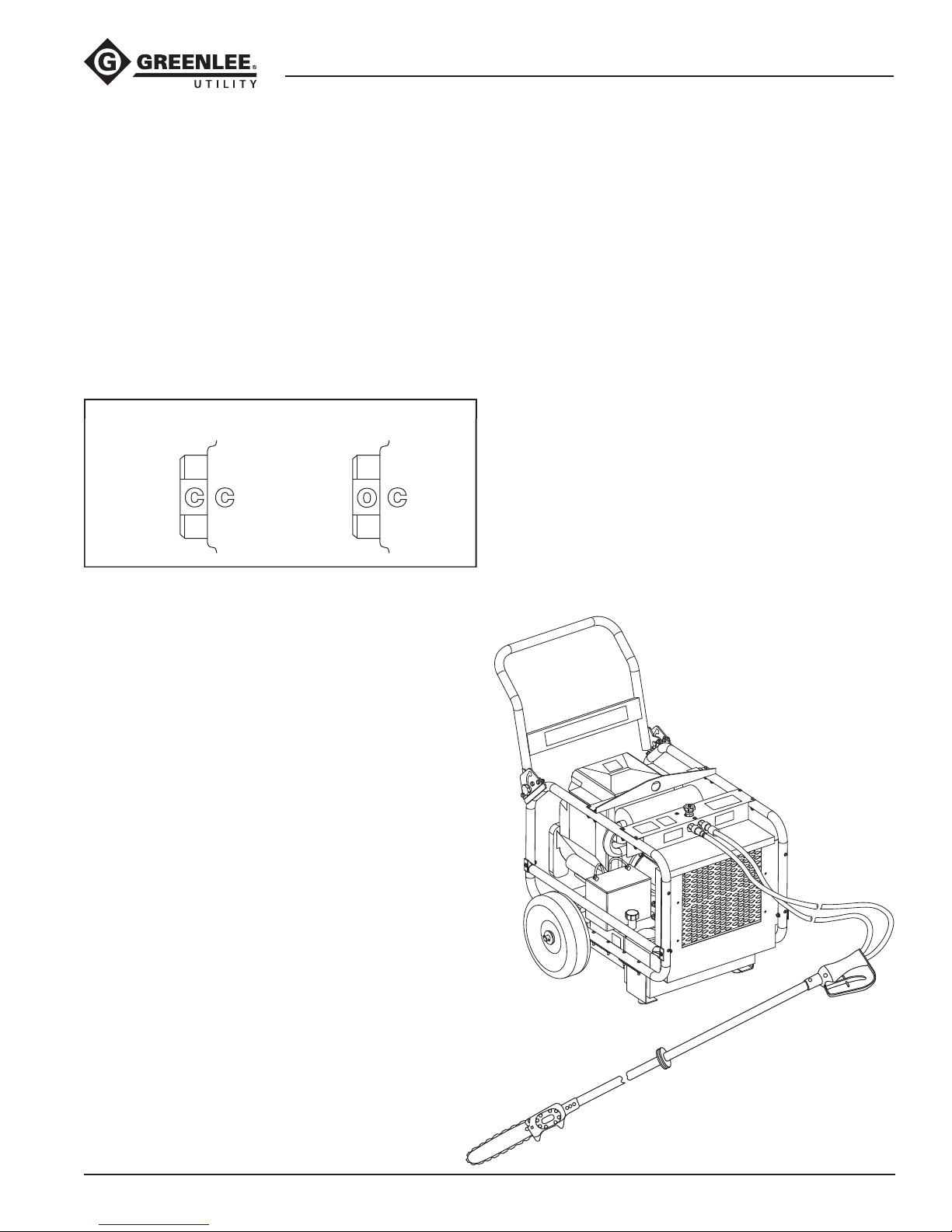
Setting the Super Spool
The Super Spool allows the tool to be used with either
open-center or closed-center hydraulic systems.
Open-center Hydraulic System
Use a wrench to turn the Super Spool until the letter “O”
on the spool is aligned with the letter “C” on the tool
handle.
Closed-center Hydraulic System
Use a wrench to turn the Super Spool until the letter “C”
on the spool is aligned with the letter “C” on the tool
handle.
Setting the Super Spool Position
Closed-center Open-center
Hose Connections
Connecting Hoses
1. Move the ow lever on the hydraulic power source
to the OFF position.
2. Stop the hydraulic power source.
3. Connect the tank hose to the tank (or return) port
on the power source, and then to the tank port on
the tool.
4. Connect the pressure hose to the pressure port or
hose coupler on the tool, and then to the pressure
port on the power source.
Disconnecting Hoses
1. Move the ow lever on the hydraulic power source
to the OFF position.
2. Stop the hydraulic power source.
3. Disconnect the pressure hose from the power
source, and then from the tool.
4. Disconnect the tank hose from the tool, and then
from the power source.
5. Install dust caps over the ports to prevent
contamination.
Hoses and Fittings
Installation and Maintenance
See publication 99930323, SAE J1273
(Hose and Hose Assemblies).
Replacement
See a Greenlee Utility catalog or Greenlee Utility
publication 99910322, Low Pressure Quick Couplers,
Adapters and Hoses.
Typical Setup
Greenlee / A Textron Company 4455 Boeing Dr. • Rockford, IL 61109-2988 USA • 815-397-7070
13
Page 14
Operation
Long-Reach Chain Saws (Foam-filled)
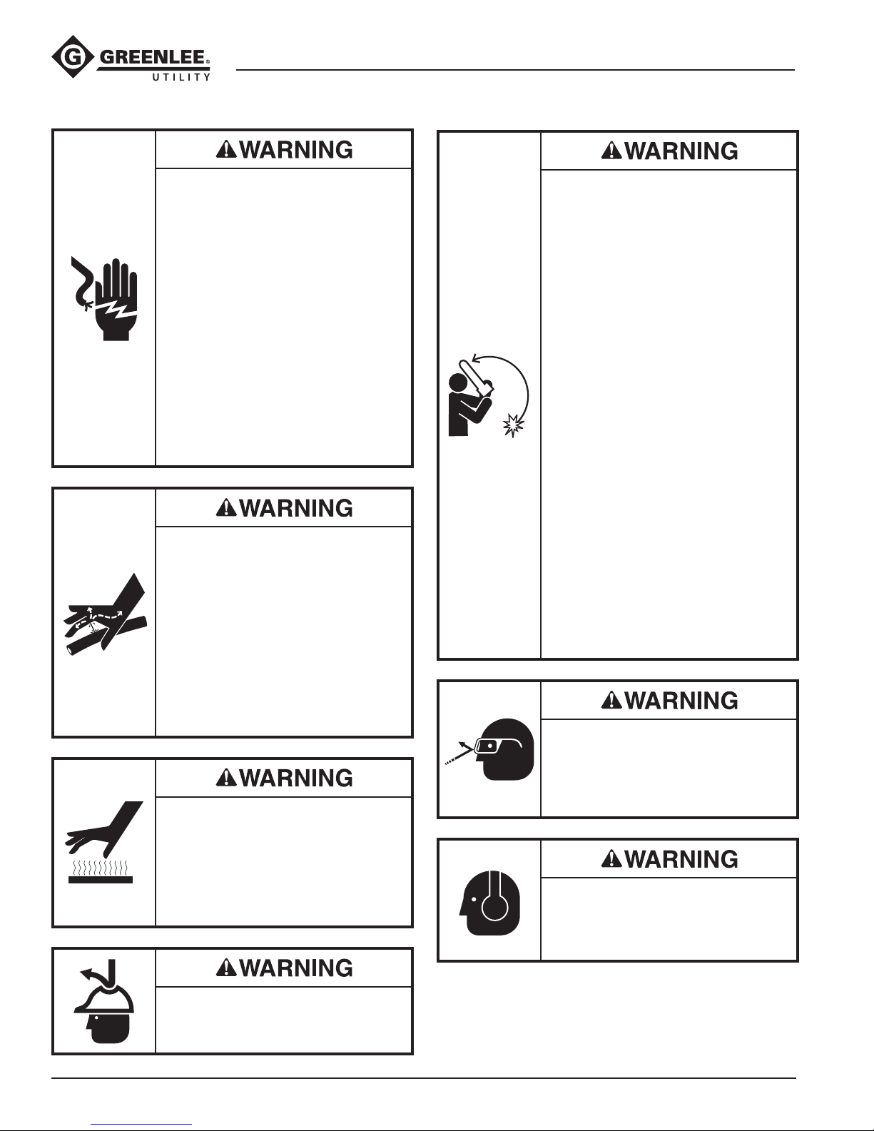
Electric shock hazard:
• This tool was tested to meet OSHA
1910.269 (dry test) when manufac-
tured. It must be properly cleaned
and maintained to ensure contin-
ued non-conductive properties.
When using this unit near energized
electrical lines, use only certied
non-conductive hoses and proper
personal protective equipment.
• Keep berglass extension clean
and dry when working around
energized electrical lines.
Accumulated oil or dirt reduces the
insulating properties of the tool.
Failure to observe these warnings
could result in severe injury or death.
Skin injection hazard:
• Do not use hands to check for leaks.
• Do not hold hose or couplers while
the hydraulic system is pressurized.
• Depressurize the hydraulic system
before servicing.
Oil under pressure easily punctures
skin causing serious injury, gangrene
or death. If you are injured by escaping oil, seek medical attention
immediately.
Saw body, bar, blade and other
components will be hot during and
after use. Use care when handling the
saw. Hot surfaces can cause serious
burns.
Failure to observe this warning could
result in severe injury or death.
Before operating the saw, read and
understand the following explanations
in this manual:
• Pull-In
Pull-in can occur when the blade
at the bottom of the bar contacts
a foreign object, such as a nail, or
when the blade is pinched in the
cut.
The saw will be suddenly and force-
fully pulled away from the operator.
• Push-back
Push-back can occur when the
blade at the top of the bar contacts
a foreign object, such as a nail, or
when the blade is pinched in the cut.
The saw will be suddenly and
forcefully pushed back toward the
operator.
• Kickback
Kickback can occur when the
chain at the guide bar tip contacts
anything. The bar of the saw will
travel upward and back, toward the
operator.
Failure to observe this warning could
result in severe injury or death.
Wear eye protection when operating
or servicing this tool.
Failure to wear eye protection could
result in serious eye injury from ying
debris or hydraulic oil.
Wear hearing protection when using
this tool.
Long-term exposure to high noise
levels could result in hearing loss.
Wear a hard hat when using this tool.
Failure to observe this warning could
result in severe injury or death.
Greenlee / A Textron Company 4455 Boeing Dr. • Rockford, IL 61109-2988 USA • 815-397-7070
14
Page 15
Operation (cont’d)
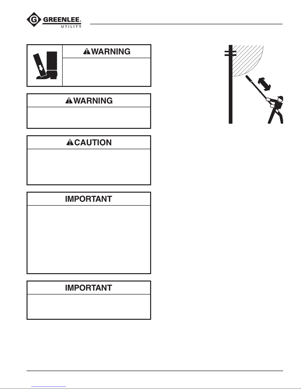
Wear foot protection when using this
tool.
Failure to observe this warning could
result in serious injury.
Do not disconnect tool, hoses or ttings while the
power source is running or if the hydraulic uid is hot.
Hot hydraulic uid could cause serious burns.
Vibration hazard:
Apply just enough pressure to do the work. Applying
excess pressure to the tool can cause operator
discomfort or temporary numbness.
Failure to observe this precaution may result in injury.
• Check the operation of the automatic oiler
frequently. See Checking and Setting the Automatic
Chain Oiler in this manual.
• Check the chain frequently for proper tension and
sharpness. Tension and sharpen as necessary.
See the instructions under Saw Chain and Bar
Maintenance.
• Check the uid level of the power source reservoir
frequently. The automatic oiler uses hydraulic uid
to lubricate the bar and chain, and will cause the
uid level to drop.
Emergency stop procedure:
1. Release the trigger.
2. Shut off the hydraulic power source.
Long-Reach Chain Saws (Foam-filled)
These additional instructions are derived from EN
50110-1:
• To avoid electrical
danger and prevent
injury or electrocution:
a) the operator must
have the necessary
technical knowledge
or experience
or
b) the operator must
work under the
direct supervision of
another person who
has the necessary technical
knowledge or experience.
• This tool must not be used under adverse environmental conditions. These include a lightning storm,
any sign of an approaching lightning storm (such as
thunder), and poor visibility.
• If any electrical lines or other electrical components
carry voltages greater than 50 VAC or 120 VDC,
ensure that:
a) live parts cannot be touched — use screens,
barriers, an enclosure, or insulating covering
or
b) the “live working zone” cannot be reached
with
either parts of the body, the tool, or any
accessories.
The live working zone is the distance from any
electrically live part, based on the voltage carried
by the live part. Refer to EN 50110-1, Annex A for
this information.
Note: Maintain proper footing and balance while using
the tool. Do not over-reach. Unsuitable footing and
balance may not allow counteracting normal or unexpected movement of the power tool.
1. Grasp the front handle with one hand and the trigger
handle with the other hand.
2. Move the trigger interlock latch forward and pull the
trigger until the saw reaches full rpm.
3.
Feed the rotating saw chain using a steady, constant
pressure.
Note: Cut straight through the wood — do not twist
the saw in the cut.
4. To stop the saw, release the trigger.
5. When the tool is not in use, stop the power source
to reduce heat and wear.
Greenlee / A Textron Company 4455 Boeing Dr. • Rockford, IL 61109-2988 USA • 815-397-7070
15
Page 16
Maintenance
Long-Reach Chain Saws (Foam-filled)
Wear eye protection when operating
or servicing this tool.
Failure to wear eye protection could
result in serious eye injury from ying
debris or hydraulic oil.
Make a note of the time it takes the chain to stop
completely (stop time). Compare to the stop times
recorded during previous months.
An increasing stop time indicates that the trigger
valve components are dirty or worn. Have the
tool cleaned or repaired by an Greenlee Utility
Authorized Service Center.
Annually
If required by your organization, have the tool inspected
by an Greenlee Utility Authorized Service Center.
Do not change accessories, inspect, adjust or
clean tool when it is connected to a power source.
Accidental startup can result in serious injury.
Failure to observe these warnings could result in
severe injury or death.
SCHEDULE
Use this schedule to maximize the tool’s service life.
Notes:
Keep all decals clean and legible. Replace decals when
necessary.
When disposing of any components (hydraulic hoses,
hydraulic fluid, worn parts, etc.), do so in accordance
with federal, state and local laws or ordinances.
Daily
1. Wipe all tool surfaces clean.
2. Inspect the entire chain before use. Tension and
sharpen the chain as instructed under Saw Chain
and Bar Maintenance. An improperly sharpened,
dull, worn or damaged chain increases the risk of
kickback.
3. Check the operation of the automatic oiler before
use as instructed under Checking and Setting the
Automatic Chain Oiler. An improperly set oiler can
accelerate the wear of the chain and bar.
4. Inspect the hydraulic hoses and ttings for signs
of leaks, cracks, wear or damage. Replace if
necessary.
5. Install dust caps over the hydraulic ports when the
tool is disconnected.
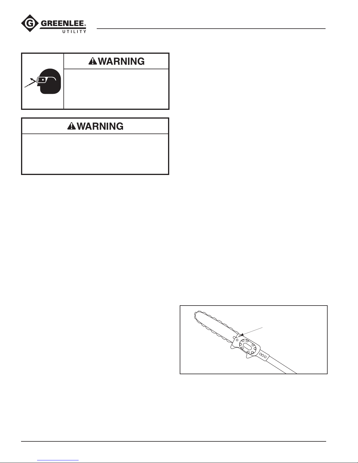
CHECKING AND SETTING
THE AUTOMATIC CHAIN OILER
The automatic chain oiler provides a constant supply of
oil to lubricate the bar and chain whenever the saw is
operating. An adjustment screw controls the amount of
oil supplied.
Before adjusting the automatic oiler, clean the oil
passage in the base of the guide bar rst. Oil dripping
off the saw head, sprocket cover or bar indicates that
the oil passage is plugged.
1. Run the saw at full rpm.
2. If the tip of the saw gives off a ne spray of oil, the
automatic oiler is working properly. If the saw does
not give off a spray of oil, adjust the oiler.
Note: For better results, hold saw so that the tip of
the saw blade is pointing toward a clean sheet of
paper or cardboard and run the saw at full rpm. If
the automatic oiler is working properly, the paper or
cardboard should soon show small droplets of oil.
3. Stop the hydraulic power source.
4. Fully tighten the oiler screw until it is seated.
Loosen1/4 turn counterclockwise.
Automatic Oiler Adjustment Screw
Automatic Oiler
Adjustment Screw
Monthly
1. Perform a thorough inspection of the hydraulic
hoses and ttings as described in publication
99930323, SAE J1273 (Hose and Hose Assemblies).
2. Perform the Bar Service procedure as described
under Saw Chain and Bar Maintenance.
3. Run the saw at full RPM and release the trigger.
Greenlee / A Textron Company 4455 Boeing Dr. • Rockford, IL 61109-2988 USA • 815-397-7070
5. Start the hydraulic power source.
6. Continue to loosen the oiler screw 1/4 turn at a time
until the oiler output is adjusted correctly.
16
Page 17
Long-Reach Chain Saws (Foam-filled)
Maintenance (cont’d)
SAW CHAIN AND BAR MAINTENANCE
New Chain Break-In
1. Run the saw at low chain speed without cutting
wood for 2 to 3 minutes. Check the output from the
automatic oiler.
2. Stop the hydraulic power source. Disconnect the
hoses. Allow the bar and chain to cool. Check the
tension and adjust if necessary.
3. Connect the hoses. Start the power source. Make a
few easy cuts at moderate chain speed.
4. Stop the hydraulic power source. Disconnect the
hoses. Allow the bar and chain to cool. Check the
tension and adjust if necessary.
5. Connect the hoses. Start the power source. Use the
saw for moderate cuts during the next 30 minutes of
use.
Checking Chain Tension
1. Stop the hydraulic power source. Disconnect the
hoses. Allow the bar and chain to cool.
2. Pull the saw chain around the bar. The chain should
rotate around the bar easily. If it does not, see Chain
is Difcult to Rotate Manually in the Troubleshooting
table.
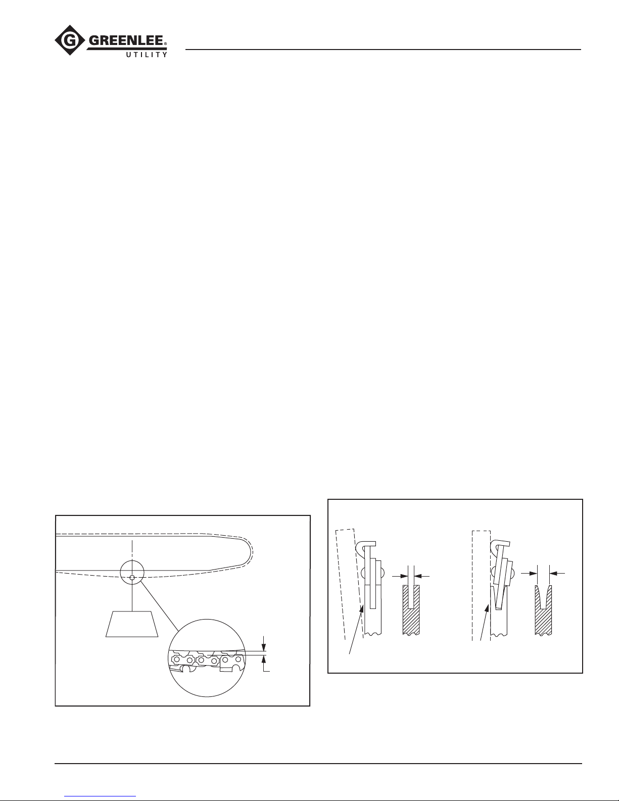
3. Check the tension as follows:
Pull the saw chain away from the bar (see the
illustration) using approximately 4.4 Newtons (2
lb) of force. The clearance between the chain and
bar should be approximately 3.2 mm (1/8"). If there
is too much or too little clearance, proceed to
Adjusting Chain Tension.
Proper Chain Tension
Adjusting Chain Tension
1. Loosen the two guide bar mounting screws.
2. Turn the saw chain tension adjusting screw until the
proper tension is achieved, as follows:
Pull the saw chain away from the bar (see the
illustration) using approximately 4.4 Newtons (2 lb)
of force. The clearance between the chain and bar
should be approximately 3.2 mm (1/8").
3. Hold the bar nose up and tighten the two bar ange
nuts. Torque to 16.9 Newton-meters (150 in-lb).
4. Check the chain tension again.
5.
Rotate the chain around the bar manually. If you hear
a clicking noise, the chain drive links are hitting the
bar. Repeat the Adjusting Chain Tension procedure.
Bar Service
1. Mark the top side of the bar with a grease pencil or
marker.
2. Remove the chain and bar. Use a small cleaning
brush to remove all residue from the bar groove.
3. Clean the oil passage at the base of the guide bar.
Use any instrument small enough to thoroughly
clean the passage.
4. Check the bar rails for wear by placing a straight
edge against the side of the bar and one cutter.
• Clearance between the bar and straight edge
indicates that the bar rails are not worn.
• If the chain leans and there is little or no clearance
between the bar and straightedge, the bar rails
are worn and the bar should be replaced.
Checking Rails for Wear
CHAIN IS STRAIGHT
CHAIN LEANS
Approx.
4.4 Newtons
(2 lb.)
Greenlee / A Textron Company 4455 Boeing Dr. • Rockford, IL 61109-2988 USA • 815-397-7070
Approx.
3.2 mm
(1/8")
17
STRAIGHTEDGE
Clearance
Rails are
not worn.
STRAIGHTEDGE
No
Clearance
Rails are worn.
Replace bar.
Page 18
Maintenance (cont’d)
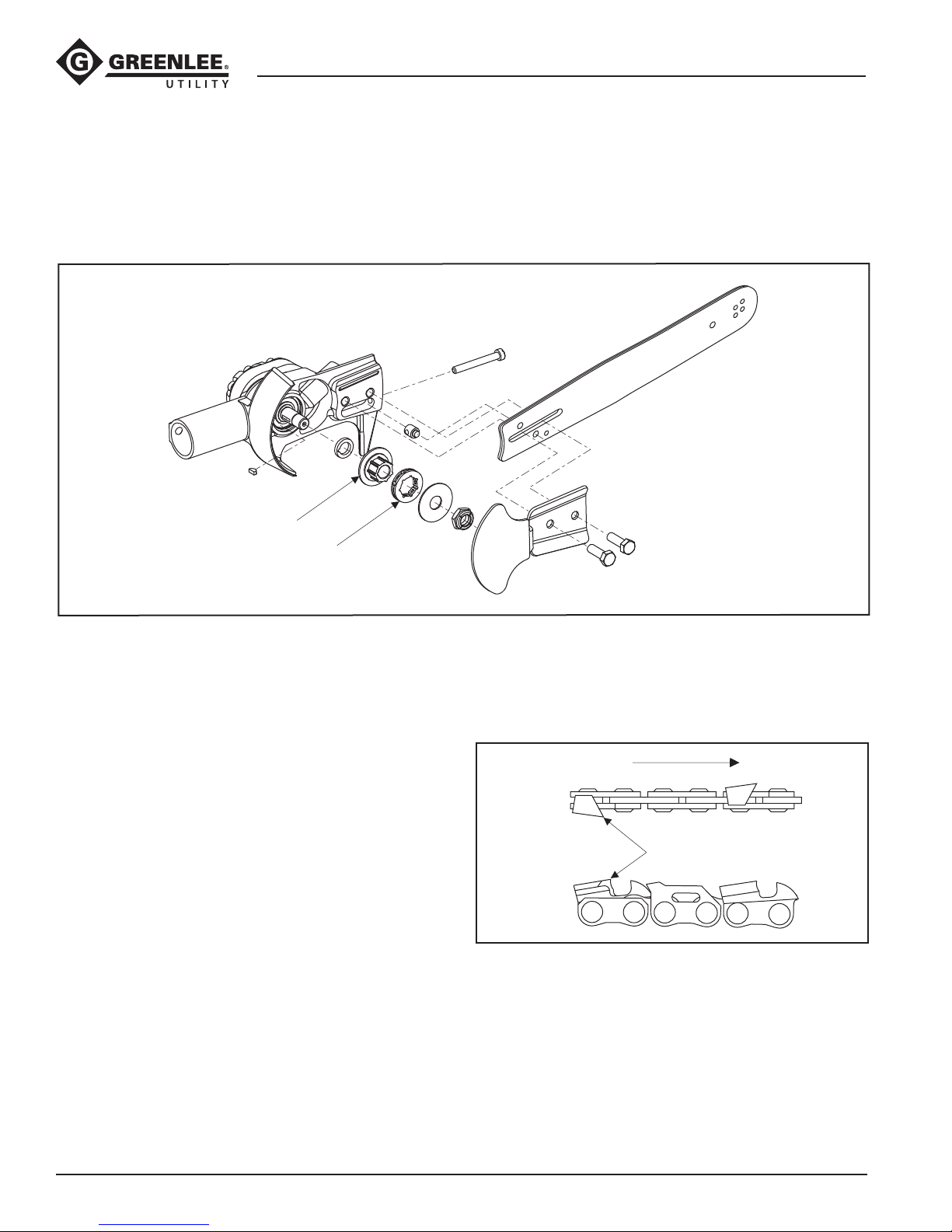
5. Inspect the rim sprocket and sprocket adapter.
Replace if worn or damaged.
Rim Sprocket and Sprocket Adapter
Long-Reach Chain Saws (Foam-filled)
Sprocket Adapter
Rim Sprocket
6. Use the mark made in Step 1 to install the bar
upside down, so that the bar will wear evenly.
7. Install the chain as shown. Adjust the tension of the
chain as described under Adjusting Chain Tension.
Direction of Chain Travel
Top View
Cutting Edge
Side View
Greenlee / A Textron Company 4455 Boeing Dr. • Rockford, IL 61109-2988 USA • 815-397-7070
18
Page 19
Maintenance (cont’d)
Long-Reach Chain Saws (Foam-filled)
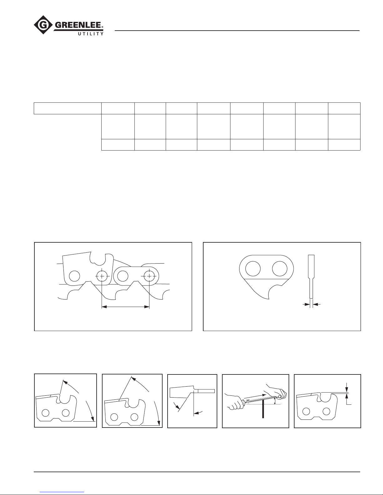
SHARPENING THE SAW CHAIN
The saw chain must be sharpened to the manufacturer’s
specications. If the saw chain is not properly sharpened, the risk of kickback increases.
See Illustration:
Figure A
Pitch
Figure B
Gauge
Figure C
Side
Plate
Angle
.325"
.058"
85°
Saw Chain Pitch
See Figure A. Pitch refers to the saw chain measure-
ment.
A chain’s pitch is the distance between any three
consecutive rivets divided by two. Example: .65 divided
by two equals .325 pitch.
Figure A
Pitch
If using a ling guide or hand-held grinder, refer to the
manufacturer’s instructions provided with the unit.
All Long-Reach Chain Saws are equipped with the
following chain:
Figure D
Top Plate
Cutting
Angle
60°
Figure E
Top Plate
Filing
Angle
30°
—
File
Guide
Angle
10°
Figure F
Depth
Gauge
Setting
.025"
—
Round
File
Size
3/16"
Saw Chain Gauge
See Figure B. Gauge refers to the thickness of that
portion of the drive link which ts into the guide bar
groove. The guide bar and saw chain gauge must
match. Industry standards are .050, .058 and .063.
Figure B
Gauge
This distance divided
by two equals Pitch “A”.
Figure C
Side Plate Angle
Figure D
Top Plate Cutting Angle
“C”
Greenlee / A Textron Company 4455 Boeing Dr. • Rockford, IL 61109-2988 USA • 815-397-7070
“D”
Figure E
Top Plate Filing Angle
“E”
19
Thickness of bottom section
of drive link equals Gauge “B”.
File Guide Angle
10°
Figure F
Depth Gauge Setting
“F”
Page 20
Maintenance (cont’d)
Long-Reach Chain Saws (Foam-filled)
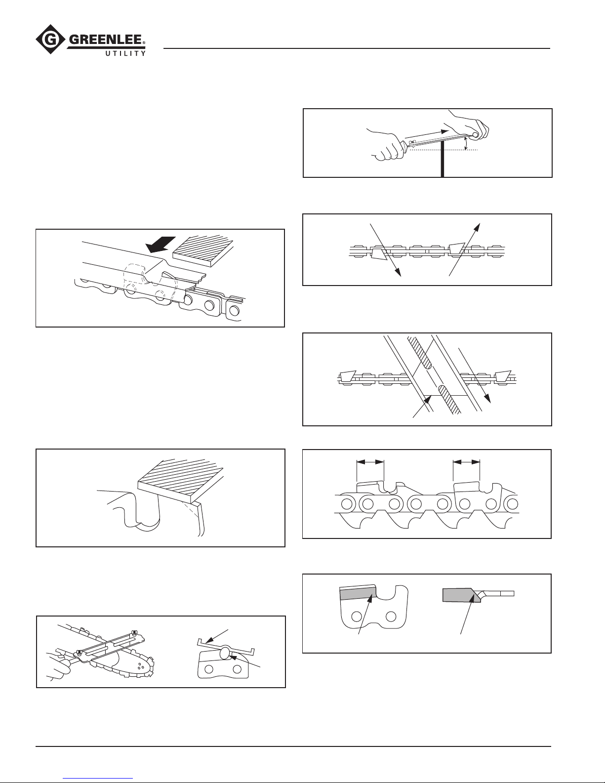
Filing Depth Gauges
1. If the cutters are sharpened with a le holder, check
and lower the depth gauges before sharpening the
cutters.
2. Check the depth gauges every third sharpening.
3. Place the depth gauge tool on the cutter. If the
depth gauge projects, le it level with the top of the
tool. Always le from the inside of the saw chain
toward an outside cutter.
Lowering Depth Gauges
4. Round off the front corner to maintain the original
shape of the depth gauge after using the depth
gauge tool. Always follow the recommended depth
gauge setting of the chain manufacturer. This is
important for maximum performance throughout
the saw chain’s life as well as for protection against
kickback.
2. Guide the le at a 10° angle to the cutters.
10°
3. File the cutters on one side of the saw chain from
the inside out. File on the forward stroke only.
4. Keep the line on the le holder parallel to the center
of the saw chain. Reverse the procedure for the
other side.
File Holder Line
Rounding Off Depth Gauges
Filing Cutters — General
1. Support the le holder on the cutter top plate and
depth gauge as shown.
File Holder
File
5. Keep all cutters the same length.
6. File enough to remove any damage to the cutting
edges (side plate and top plate) of the cutter.
Side Plate Top Plate
Greenlee / A Textron Company 4455 Boeing Dr. • Rockford, IL 61109-2988 USA • 815-397-7070
20
Page 21
Long-Reach Chain Saws (Foam-filled)
Troubleshooting
Before troubleshooting, determine whether the problem is in the tool, the hoses, or the power source. Substitute a
tool, hoses, or power source known to be in good working order to eliminate the item that is not operating.
If the problem is in the tool, see the troubleshooting table in this manual. If the problem is in the power source, see
the troubleshooting section of the power source instruction manual.
Problem Probable Cause Probable Remedy
Tool does not operate. Improper power source. Verify that the power source
meets the specications. See the
Specications section.
Hydraulic uid level low. Check the uid level. Check system
for leaks.
Incorrect hydraulic uid viscosity. Use hydraulic uid with the correct
viscosity. See the Specications
section.
Tool operates slowly or erratically. Hydraulic uid cold. Allow uid to warm to the operating
temperature. Actuate the tool intermittently to reduce the warming
time.
Trigger difcult to operate; trigger
sticks when released.
Chain runs in wrong
direction.
Power source not adjusted
correctly.
Hydraulic uid level low. Check the uid level. Check system
Air in the hydraulic system. See power source manufacturer's
Incorrect hydraulic uid viscosity. Use hydraulic uid with the correct
Dirt or gummy deposits on trigger or
spool.
Hose connections at tool are
reversed.
Refer to the power source operator’s
manual. Set the ow and pressure to
correspond with the tool.
for leaks.
instructions for removing air from the
system.
viscosity. See the Specications
section.
Clean and lubricate trigger and
trigger spool.
Depressurize hydraulic system.
Switch the hose connections.
Greenlee / A Textron Company 4455 Boeing Dr. • Rockford, IL 61109-2988 USA • 815-397-7070
21
Page 22
Long-Reach Chain Saws (Foam-filled)
Troubleshooting (cont’d)
Problem Probable Cause Probable Remedy
Chain does not cut. Chain dull. Remove chain and sharpen to chain
manufacturer’s specications or
replace with a sharp chain.
Too much tension on the chain. Adjust chain tension. See Saw Chain
and Bar Maintenance.
Automatic oiler not lubricating
chain and bar.
Chain installed backward. Remove chain and install correctly.
Guide bar worn. Inspect guide bar rails for wear. See
Tool feels hot. Hydraulic uid level low. Check the uid level. Check system
Incorrect hydraulic uid viscosity. Use hydraulic uid with the correct
Hydraulic uid dirty. See the power source owner’s
Chain is difcult to rotate manually. Hydraulic pressure trapped in
saw motor.
Chain and bar improperly
adjusted.
See Checking and Setting the
Automatic Chain Oiler.
Saw Chain and Bar Maintenance. If
excessively worn, replace guide bar.
for leaks.
viscosity. See the Specications
section.
manual for procedure to replace
hydraulic oil and lter.
Release hydraulic pressure by using
proper hose disconnection proce-
dure. See Hose Connections in this
manual.
See Adjusting Chain Tension under
Saw Chain and Bar Maintenance in
this manual.
Greenlee / A Textron Company 4455 Boeing Dr. • Rockford, IL 61109-2988 USA • 815-397-7070
Chain drive links damaged. Remove chain and inspect drive
links.
Bar groove damaged. Remove chain and inspect bar
groove.
22
Page 23
Long-Reach Chain Saws (Foam-filled)
SERVICE INFORMATION
Service:
Have your tool serviced by a qualified repair
person using only identical replacement parts.
This will ensure that the safety of the power tool is
maintained.
Failure to observe this warning could result in severe
injury or death.
Disassembly
Complete disassembly of the tool is not recommended.
If a complete overhaul is necessary, return the tool to
your nearest Greenlee Utility Authorized Service Center.
The disassembly procedure is divided into sections of
the tool. Disassemble only the section(s) necessary to
complete the repair.
Disassemble the tool on a at, clean surface. Take care
not to lose or damage any parts that may fall free during
disassembly.
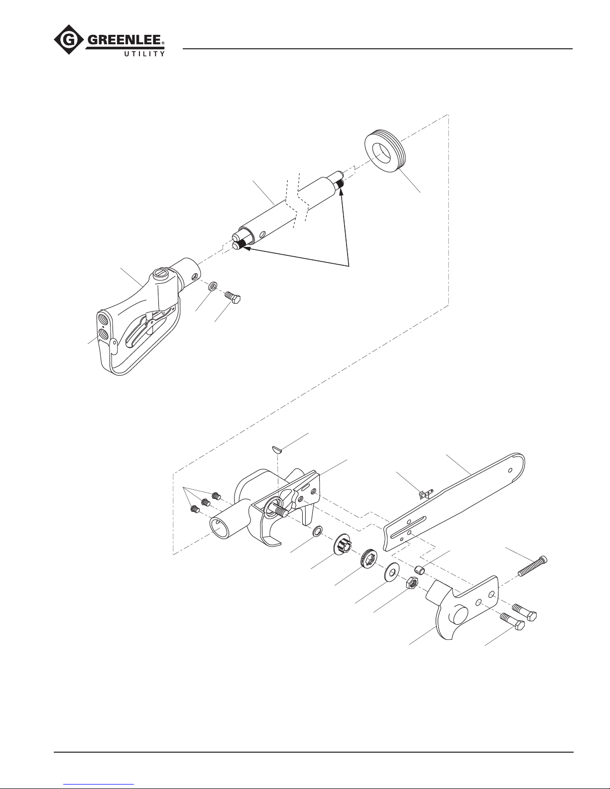
Inner and Outer Tubes
1. Remove hex head cap screw (10) and lock washer
(11) which secure outer tube (4). Remove tube
assembly (2) from ports of handle assembly (8).
2. Remove three oval head machine screws (9)
which secure tube assembly to motor assembly (1).
Remove tube assembly from motor assembly.
Saw Blade and Chain
1. Remove hex head cap screws (15). Remove cover
(14). Remove saw chain from sprocket (26). Remove
bar (12) from motor assembly (1). Dog and tension
bolt may be removed from saw head if necessary.
2. Remove stop nut (19), sprocket adapter (26), rim
sprocket (18), sprocket key (17), and sprocket
washer (16) from drive shaft.
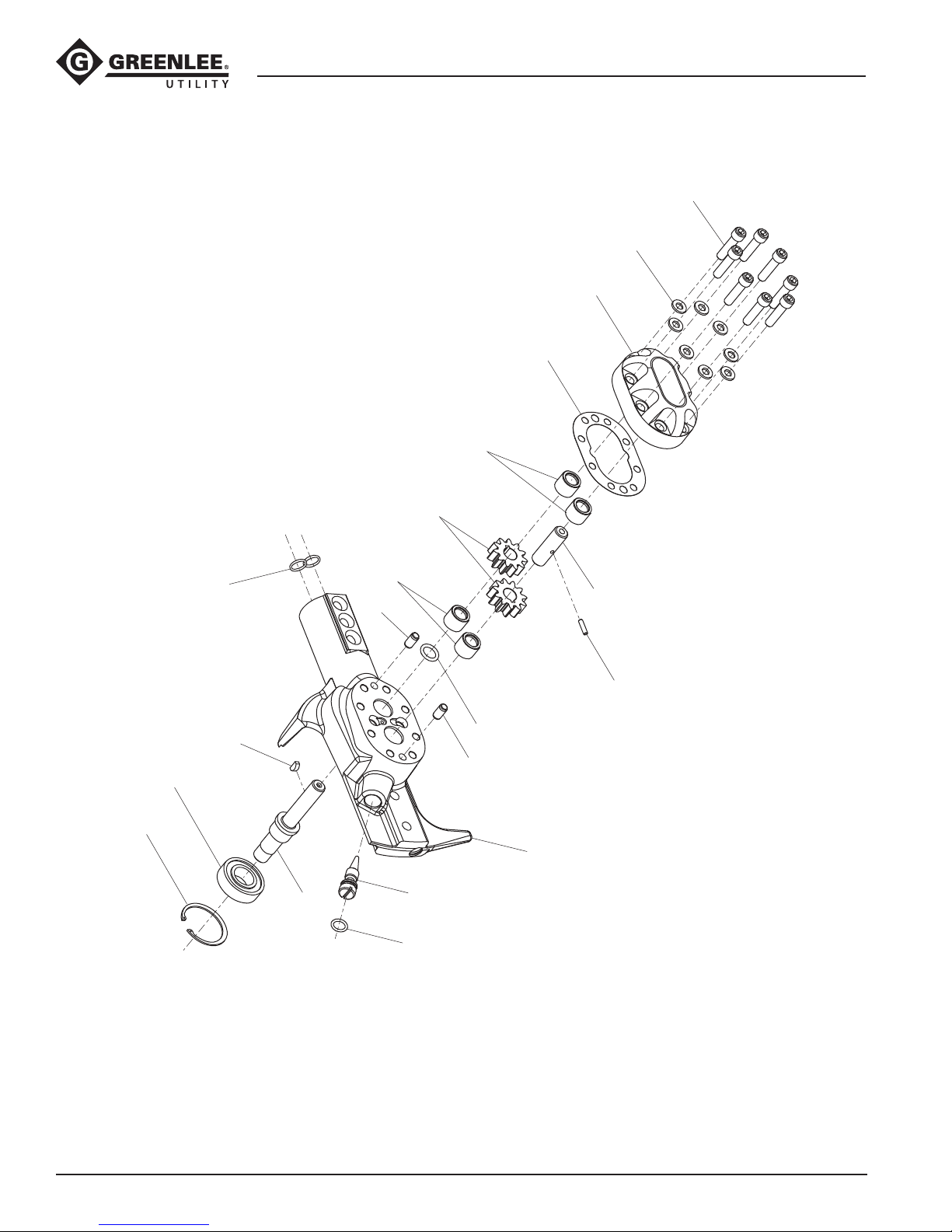
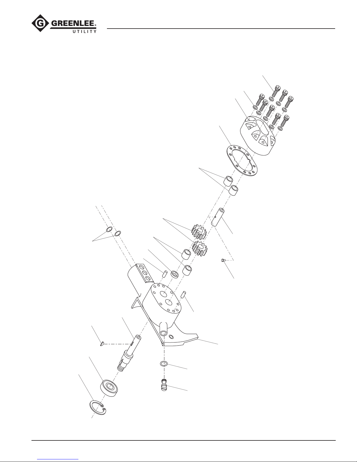
Motor Assembly
1. Scribe a line across motor cap (55) and saw head
assembly (52) to help align parts correctly during
reassembly. Remove socket head cap screws (66).
Remove motor cap from saw head assembly.
2. Remove idler shaft (58). Remove gear (61) from
idler shaft (58). Remove gear (61) and Woodruff key
(59) from drive shaft (57). Remove gasket (62) from
motor. Remove dowel pins (63), if necessary.
3. Remove retaining ring (65). Drive shaft may be
driven out of saw head assembly, threaded end rst,
using a rubber mallet. Remove ball bearing (64) from
drive shaft.
4. Bearings (53 and 56) should be removed from
saw head assembly and motor cap only if they are
damaged. Bearings are pressed in, and should be
removed only if the necessary equipment to replace
them is available.
5. Remove metering screw (68), which controls oil ow
to automatic chain oiler. Remove O-ring (67).
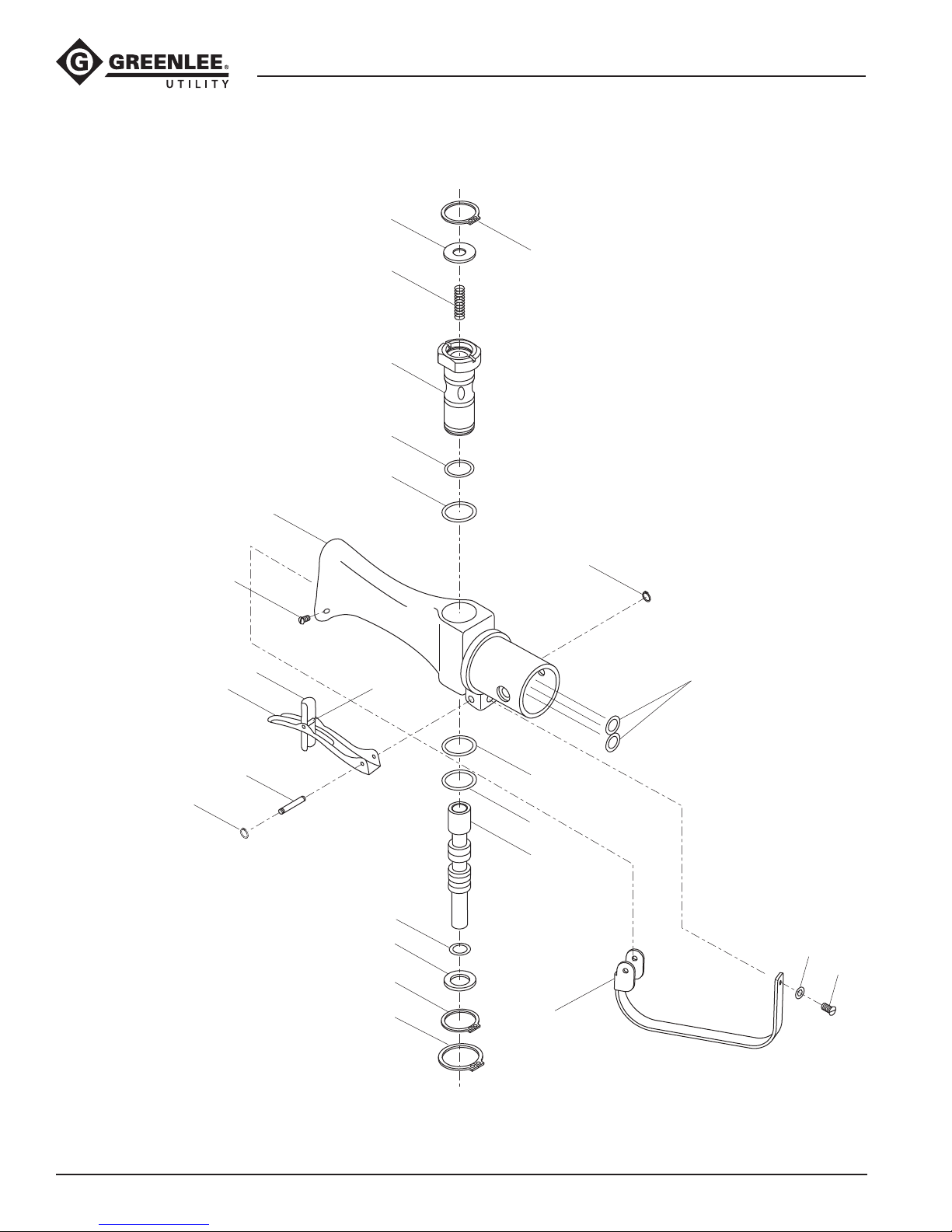
Handle Assembly
1. Remove two round head machine screws (39) and
lock washers (40) from guard (38). Remove guard
(38) from handle assembly (27).
2. Remove retaining ring (46) and trigger pivot (45)
which secures trigger (41).
3. Remove internal retaining ring (30) from sleeve (28)
which will allow spring (33) and washer (32) to be
removed.
4. Remove internal retaining ring (50) and washer (37).
5. Remove spool (35) from sleeve (28).
6. Remove external retaining ring (49). Pull sleeve (28)
out of handle (27).
Greenlee / A Textron Company 4455 Boeing Dr. • Rockford, IL 61109-2988 USA • 815-397-7070
Inspection
Clean all parts with solvent and dry them thoroughly.
Inspect each component as described in this section.
Replace any component that shows wear or damage.
1. Saw Head Assembly and Motor Cap Assembly:
Inspect mating surfaces, gear cavities, oil passageways, etc. for grooves or nicks. If any component
shows wear or damage, replace the entire assembly
with the bearings already pressed in.
2. Inspect all other disassembled components for
cracks, grooves or nicks.
111
Page 24
Assembly
Long-Reach Chain Saws (Foam-filled)
Refer to the Illustrations and Parts List for correct
orientation and placement of parts.
Replace any O-rings, V-rings, seals, and gaskets on
parts that have been disassembled. Apply hydraulic
uid or O-ring lubricant to all O-rings and all metal
surfaces which they must slide over. When installing
an O-ring which must slide over sharp surfaces, use a
rolling motion and be careful not to damage the O-ring.
Wherever the assembly results in metal-to-metal
contact, coat the surfaces with hydraulic uid or O-ring
lubricant.
Motor Assembly
1. If bearings (53 and 56) have been removed from the
motor cap (55) and saw head (52), replace them.
Install O-ring (54) in saw head.
2. Install ball bearing (64) over threaded end of drive
shaft (57). Install non-threaded end of drive shaft
(57) through front of cavity in saw head assembly
(52). Secure with retaining ring (65). Install drive
pin (60) into idler shaft (58) and install idler shaft
into cavity on rear side of saw head assembly (52).
Install Woodruff key (59) into drive shaft (57).
3. Install one gear (61) onto idler shaft (58), aligning
notch in gear over drive pin (60). Install one gear
(61) on drive shaft (57), aligning notch in gear over
Woodruff key (59).
4. Install gasket (62) on saw head assembly (52).
Install dowel pins (63) in saw head assembly.
Install motor cap (55) on saw head assembly,
using the line scribed during disassembly to align
parts correctly. Secure motor cap (55) to saw head
assembly with washers (70) and socket head cap
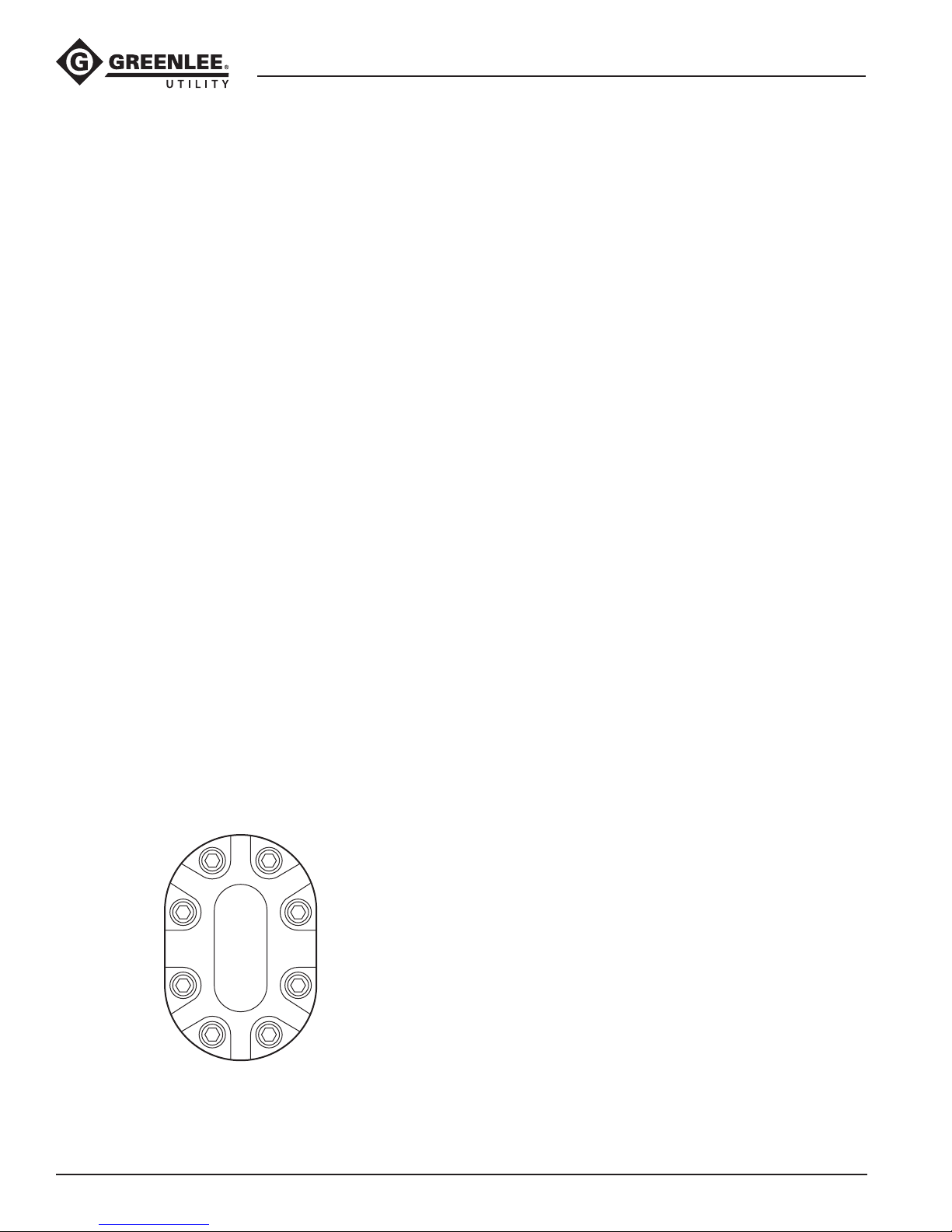
screws (66). Torque to 9 newton-meters (80 in-lb).
Torque Sequence
5. If metering screw has been removed, install O-ring
(67) on metering screw (68). Install metering screw,
bottoming it out in the cavity, and backing it off
about 1/2 turn.
Note: Metering screw is not adjusted at this point.
After assembly is completed, adjust automatic oiler
before using the tool.
6. If O-rings (69) have been removed, install a new
O-ring inside each port of saw head assembly (52).
Saw Bar and Chain
1. Install sprocket key (17), sprocket washer (16),
sprocket (18), sprocket adapter (26), and stop nut
(19) on threaded end of drive shaft. Ensure that
sprocket adapter is assembled onto shaft with
1.500 dia. face oriented toward stop nut.
2. Set saw head down at. Install dog (21) with small
diameter side facing out. Install adjusting screw (20)
into back side of saw head and thread into dog.
3. Place bar with chain wrapped around it onto saw
head. Ensure dog is placed in the guide hole around
the outer edge of the bar. Place cover (14) with hex
head cap screws (15) over bar and secure screws
into saw head loosely but enough to hold bar at
onto saw head with dog in guide hole.
4. Place chain around sprocket and bar.
Note: Lubricate the saw chain (13) well (especially a
new chain) before installation. Oil all joints and work
oil into rivet holes. The best way to oil a new chain is
to soak it in oil before installation.
5. Tighten adjusting screw (20) until proper tension is
achieved. (Refer to “Adjusting Chain Tension” in the
“Maintenance” section of this manual.)
6. Secure hex head cap screws (15) to 16.9 newtonmeters (150 in-lb).
5 7
1
3
8 6
Greenlee / A Textron Company 4455 Boeing Dr. • Rockford, IL 61109-2988 USA • 815-397-7070
4
2
112
Page 25

Assembly (cont’d)
Long-Reach Chain Saws (Foam-filled)
Handle Assembly
1. Install O-rings (47) in the valve handle (27).
2. Install O-ring (48) in valve handle (27). Install
O-rings (34 and 48) in sleeve (28). Install sleeve (28)
in valve handle (27). Secure with external retaining
ring (49).
3. Install O-ring (36) on spool (35). Install spool (35)
through trigger end of valve handle.
4. Install spring (33), and O-ring (32) and secure with
retaining ring (30).
5. Install washer (37) and secure with retaining ring
(50).
6. Position trigger (41) onto handle assembly. Slide
trigger pivot (45) through holes and secure with
retaining rings (46).
7. Position guard (38) onto handle assembly. Secure
with lock washer (40) and round head machine
screws (39).
Inner and Outer Tubes
By orienting the three holes of the outer tube with the
corresponding holes on the motor assembly housing,
determine which inner tube will be inserted into the
pressure port in the motor housing (denoted with a
“P”). Mark the end of this tube and the opposite end
of this tube with a dye to insure installation into the
proper port of the handle assembly, also denoted with
a “P”. Use care to install the marked tubes into the
pressure ports of the motor assembly and the handle
assembly. Improper installation will cause the saw to run
backwards.
1. Lubricate tips of inner tubes with hydraulic oil to
ease assembly. Assemble tube assembly into motor
assembly ensuring dyed tube is installed into port
denoted with a “P”. Align the three holes of the
outer tube with the corresponding holes on the
motor assembly. Apply one drop of thread-locking
compound (Loctite 242 or equivalent) to three oval
head machine screws (9). Install screws, securing
outer tube to motor assembly.
2. For proper tool operation, the same inner tube
that was installed in the pressure port of the motor
assembly (1) must be installed in the pressure port
of the handle assembly (8). Lubricate the tips of
the inner tubes with hydraulic oil to ease assembly.
Assemble tube assembly (2) into handle assembly
(8) ensuring dyed tube is installed into port denoted
with a “P”.
3. Secure the tube assembly to the handle assembly
with cap screws (10) and lock washers (11).
Greenlee / A Textron Company 4455 Boeing Dr. • Rockford, IL 61109-2988 USA • 815-397-7070
113
Page 26
Long-Reach Chain Saws (Foam-filled)
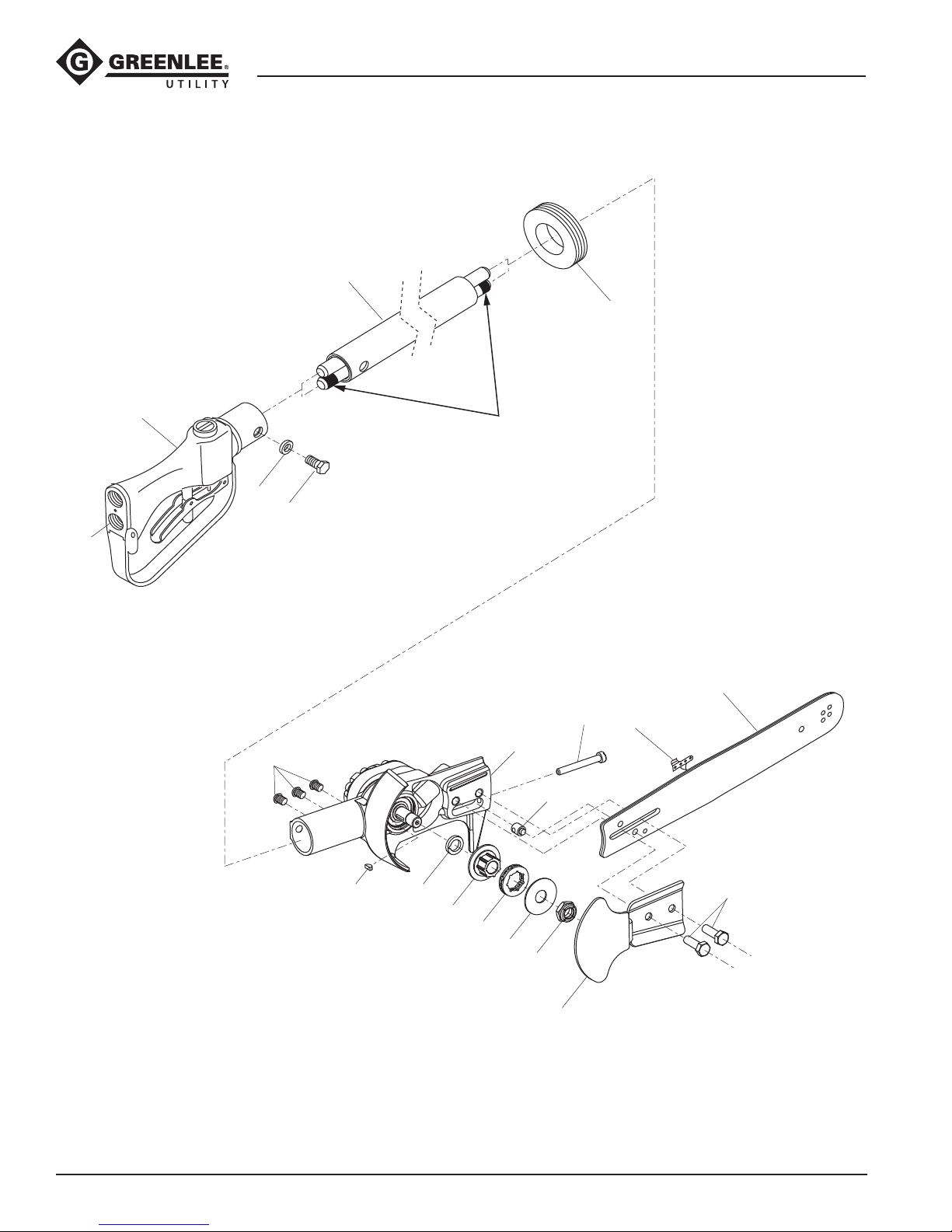
Illustration—Main for Serial Codes AMT and AMS
2
8
Assemble tube assembly (2) into motor
assembly (1) and handle assembly (8),
ensuring dyed tube is installed into ports
11
10
denoted with a “P”.
23
P
12
20
9
17
16
26
1
21
18
24
19
13
15
Greenlee / A Textron Company 4455 Boeing Dr. • Rockford, IL 61109-2988 USA • 815-397-7070
14
114
Page 27
Long-Reach Chain Saws (Foam-filled)
Illustration—Main for Serial Codes GLZ and GLY
2
8
Assemble tube assembly (2) into motor
assembly (1) and handle assembly (8),
ensuring dyed tube is installed into ports
11
10
denoted with a “P”.
23
P
17
1
13
9
16
26
18
24
19
12
21
20
Greenlee / A Textron Company 4455 Boeing Dr. • Rockford, IL 61109-2988 USA • 815-397-7070
115
14
15
Page 28
Long-Reach Chain Saws (Foam-filled)
Illustration—Motor Assembly for Serial Codes AMT and AMS
70
55
62
56
66
65
64
69
59
T
P
63
57
61
53
58
60
54
63
52
68
67
Greenlee / A Textron Company 4455 Boeing Dr. • Rockford, IL 61109-2988 USA • 815-397-7070
116
Page 29
Long-Reach Chain Saws (Foam-filled)
Illustration—Motor Assembly for Serial Codes GLZ and GLY
70
55
62
56
66
65
64
69
59
T
P
61
57
53
54
63
63
67
58
60
52
Greenlee / A Textron Company 4455 Boeing Dr. • Rockford, IL 61109-2988 USA • 815-397-7070
68
117
Page 30
Long-Reach Chain Saws (Foam-filled)
Illustration—Handle for All Serial Codes
32
41
51
42
27
33
28
34
29
43, 44, 46
30
46
47
45
46
Greenlee / A Textron Company 4455 Boeing Dr. • Rockford, IL 61109-2988 USA • 815-397-7070
36
37
50
49
31
48
35
40
39
38
118
Page 31

Long-Reach Chain Saws (Foam-filled)
Parts List for Serial Codes AMT and AMS
UPC No.
Key 78-3310- Part No. Description Qty
1 43558 50435582 Motor assembly (includes items 52–69) .............1
2 51631 52027107 Tube assembly, 75" ............................................1
51622 52027108 Tube assembly, 88" ............................................ 1
8 48818 50488180 Handle assembly (includes items 27–51) ...........1
9 Screw, machine, 1/4–20 x .500 oval head .......... 3
10 Screw, cap, 1/4–20 x .750 hex head, grade 5 ....2
11 Lock washer, 1/4" .............................................. 2
12 43369 50433695 Saw bar ............................................................. 1
13 43370 50433709 Saw chain, .325" pitch .......................................1
14 02093 52047938 Cover ................................................................. 1
15 Screw, cap, 5/16–18 x 1.00 hex head ................ 2
16 t Spacer ...............................................................1
17 t Woodruff key, #2 ................................................1
18 55101 90551010 Rim sprocket, .325" pitch ..................................1
19 t Nut, hex, 1/2–20 ................................................1
20 Screw, machine, 1/4–20 x 2.00 fillister head ......1
21 02094 52054770 Dog .................................................................... 1
23 42015 50420154 Rubber grommet ................................................1
24 t Washer, flat, .530 x 1.50 x .050 ..........................1
26 t Adapter, sprocket ...............................................1
27 48815 50488155 Handle ............................................................... 1
28 43420 50434209 Sleeve ................................................................ 1
29* O-ring, .750 x .875 x .062–90 ............................1
30 41712 50417122 Retaining ring, .750" ..........................................1
31* O-ring, .787 x .889 x .051–70 ............................1
32 41095 50410952 Cap ....................................................................1
33 42865 50428651 Spring ................................................................ 1
34* O-ring, .437 x .625 x .093–90 ............................1
35 43421 50434217 Spool ................................................................. 1
36* O-ring, .312 x .437 x .062–70 ............................1
37 41096 50410962 Washer, .355 x .615 x .030 ................................1
38 48817 50488171 Trigger guard .....................................................1
39 Screw, machine, #10-32 x .375 round head ....... 1
40 Lock washer, #10 ............................................... 1
41 04797 50047973 Trigger ...............................................................1
42 04798 50047981 Latch, trigger interlock .......................................1
43 04799 50047990 Spring, torsion ....................................................1
44 04800 50048007 Pin ..................................................................... 1
45 42547 50425471 Trigger pivot .......................................................1
46 42827 50428270 Retaining ring ....................................................4
47* O-ring, .437 x .562 x .062–90 ............................2
48* O-ring, .875 x 1.00 x .062–70 ............................1
49 54819 90548191 Retaining ring, .875" ..........................................1
50 41297 50412971 Retaining ring, .625" ..........................................1
UPC No.
Key 78-3310- Part No. Description Qty
51 Screw, cap, #10-32 x .375
button socket head ............................................2
52 02089 52058055 Saw head assembly
(includes items 53, 54 and 69) ........................... 1
53 41591 50415911 Needle bearing, .439 x .625 x .500 ....................2
54* O-ring, .500 x .687 x .093–80 ............................1
55 40405 50404053 Motor cap assembly with bearings
(includes items 56, 66, and 70) ..........................1
56 41591 50415911 Needle bearing, .439 x .625 x .500 ....................2
57 43839 50438395 Shaft .................................................................. 1
58 40114 50401144 Idler shaft...........................................................1
59 40115 50401154 Woodruff key ......................................................1
60 41593 50415930 Pin, drive, .123 x .209 square head ....................1
61 41594 50415940 Gear, 11-tooth .................................................... 2
62* Gasket, 2.09 x 3.09 x .0015 ...............................1
63 41596 50415960 Pin, dowel, .250 x .500 ......................................2
64 41598 50415981 Ball bearing ........................................................1
65 41482 50414821 Retaining ring, 1.375" ........................................1
66 Screw, cap, 1/4–20 x 1.000 socket head ...........8
67* O-ring, .375 x .500 x .062–70 ............................1
68 02092 52047936 Screw, metering .................................................1
69* O-ring, .437 x .562 x .062–90 ............................2
70 Washer, 6 mm, hard ...........................................8
Kits
* 48254 50482548 Packing kit (includes items
marked with an asterisk)
02088 52058054 Motor assembly (includes items 14, 15,
20, 21, 52–70)
48818 50488180 Handle assembly (includes items 27–51)
02089 52058055 Saw head assembly
(includes items 53, 54 and 69)
40405 50404053 Motor cap assembly
(includes items 56, 66, and 70)
04796 50047965 Safety trigger assembly (includes items 41-46)
t 12657 52028588 Drive repair kit (includes items marked with t)
Decals
46293 50462938 Decal .................................................................1
41547 50415471 Decal, Greenlee Utility ........................................1
Greenlee / A Textron Company 4455 Boeing Dr. • Rockford, IL 61109-2988 USA • 815-397-7070
119
Page 32

Long-Reach Chain Saws (Foam-filled)
Parts List for Serial Codes GLZ and GLY
UPC No.
Key 78-3310- Part No. Description Qty
1 43558 50435582 Motor assembly (includes items 52–69) .............1
2 51631 52027107 Tube assembly, 75" ............................................1
51622 52027108 Tube assembly, 88" ............................................ 1
8 48818 50488180 Handle assembly (includes items 27–51) ...........1
9 Screw, machine, 1/4–20 x .500 oval head .......... 3
10 Screw, cap, 1/4–20 x .750 hex head, grade 5 ....2
11 Lock washer, 1/4" .............................................. 2
12 43369 50433695 Saw bar ............................................................. 1
13 43370 50433709 Saw chain, .325" pitch .......................................1
14† 40846 50408461 Cover ................................................................. 1
15† Screw, cap, 5/16–18 x 1.500 hex head .............. 2
16 t Spacer ...............................................................1
17 t Woodruff key, #2 ................................................1
18 55101 90551010 Rim sprocket, .325" pitch ..................................1
19 t Nut, hex, 1/2–20 ................................................1
20† Screw, machine, 1/4–20 x 2.00 fillister head ......1
21† 40197 50401972 Dog .................................................................... 1
22* O-ring, .875 x 1.00 x .062–70 ............................2
23 42015 50420154 Rubber grommet ................................................1
24 t Washer, flat, .530 x 1.50 x .050 ..........................1
26 t Adapter, sprocket ...............................................1
27 48815 50488155 Handle ............................................................... 1
28 43420 50434209 Sleeve ................................................................ 1
29* O-ring, .750 x .875 x .062–90 ............................1
30 41712 50417122 Retaining ring, .750" ..........................................1
31* O-ring, .787 x .889 x .051–70 ............................1
32 41095 50410952 Cap ....................................................................1
33 42865 50428651 Spring ................................................................ 1
34* O-ring, .437 x .625 x .093–90 ............................1
35 43421 50434217 Spool ................................................................. 1
36* O-ring, .312 x .437 x .062–70 ............................1
37 41096 50410962 Washer, .355 x .615 x .030 ................................1
38 48817 50488171 Trigger guard .....................................................1
39 Screw, machine, #10-32 x .375 round head ....... 1
40 Lock washer, #10 ............................................... 1
41 04797 50047973 Trigger ...............................................................1
42 04798 50047981 Latch, trigger interlock .......................................1
43 04799 50047990 Spring, torsion ....................................................1
44 04800 50048007 Pin ..................................................................... 1
45 42547 50425471 Trigger pivot .......................................................1
46 42827 50428270 Retaining ring ....................................................4
47* O-ring, .437 x .562 x .062–90 ............................2
48* O-ring, .875 x 1.00 x .062–70 ............................1
49 54819 90548191 Retaining ring, .875" ..........................................1
50 41297 50412971 Retaining ring, .625" ..........................................1
51 Screw, cap, #10-32 x .375
button socket head ............................................2
UPC No.
Key 78-3310- Part No. Description Qty
52† 40595 50405950 Saw head assembly
(includes items 53, 54 and 69) ........................... 1
53 41591 50415911 Needle bearing, .439 x .625 x .500 ....................2
54* O-ring, .500 x .687 x .093–80 ............................1
55 40405 50404053 Motor cap assembly with bearings
(includes items 56, 66, and 70) ..........................1
56 41591 50415911 Needle bearing, .439 x .625 x .500 ....................2
57 43839 50438395 Shaft .................................................................. 1
58 40114 50401144 Idler shaft...........................................................1
59 40115 50401154 Woodruff key ......................................................1
60 41593 50415930 Pin, drive, .123 x .209 square head ....................1
61 41594 50415940 Gear, 11-tooth .................................................... 2
62* Gasket, 2.09 x 3.09 x .0015 ...............................1
63 41596 50415960 Pin, dowel, .250 x .500 ......................................2
64 41598 50415981 Ball bearing ........................................................1
65 41482 50414821 Retaining ring, 1.375" ........................................1
66 Screw, cap, 1/4–20 x 1.000 socket head ...........8
67*† O-ring, .375 x .500 x .062–70 ............................1
68† 40189 50401891 Screw, metering, 1/8 NPTF ................................. 1
69* O-ring, .437 x .562 x .062–90 ............................2
70 Washer, 6 mm, hard ...........................................8
Kits
* 48254 50482548 Packing kit (includes items
marked with an asterisk)
48818 50488180 Handle assembly (includes items 27–51)
40595 50405950 Saw head assembly
(includes items 53, 54 and 69)
40405 50404053 Motor cap assembly
(includes items 56, 66, and 70)
04796 50047965 Safety trigger assembly (includes items 41-46)
t 12657 52028588 Drive repair kit (includes items marked with t)
† 02090 52058056 Retrofit kit (replaces items marked with †);
converts to AMT/AMS model
Note: Motor assembly for serial codes AMT/AMS
is interchangeable as retrofit kit.
Decals
46293 50462938 Decal .................................................................1
41547 50415471 Decal, Greenlee Utility ........................................1
52024044 Decal, IEC 60855 ...............................................1
4455 Boeing Drive • Rockford, IL 61109-2988 • USA • 815-397-7070
An ISO 9001 Company • Greenlee Textron Inc. is a subsidiary of Textron Inc.
www.greenlee.com
USA Tel: 800-435-0786
Fax: 800-451-2632
Canada Tel: 800-435-0786
Fax: 800-524-2853
International Tel: +1-815-397-7070
Fax: +1-815-397-9247
 Loading...