

Page 1
INSTRUCTION MANUAL
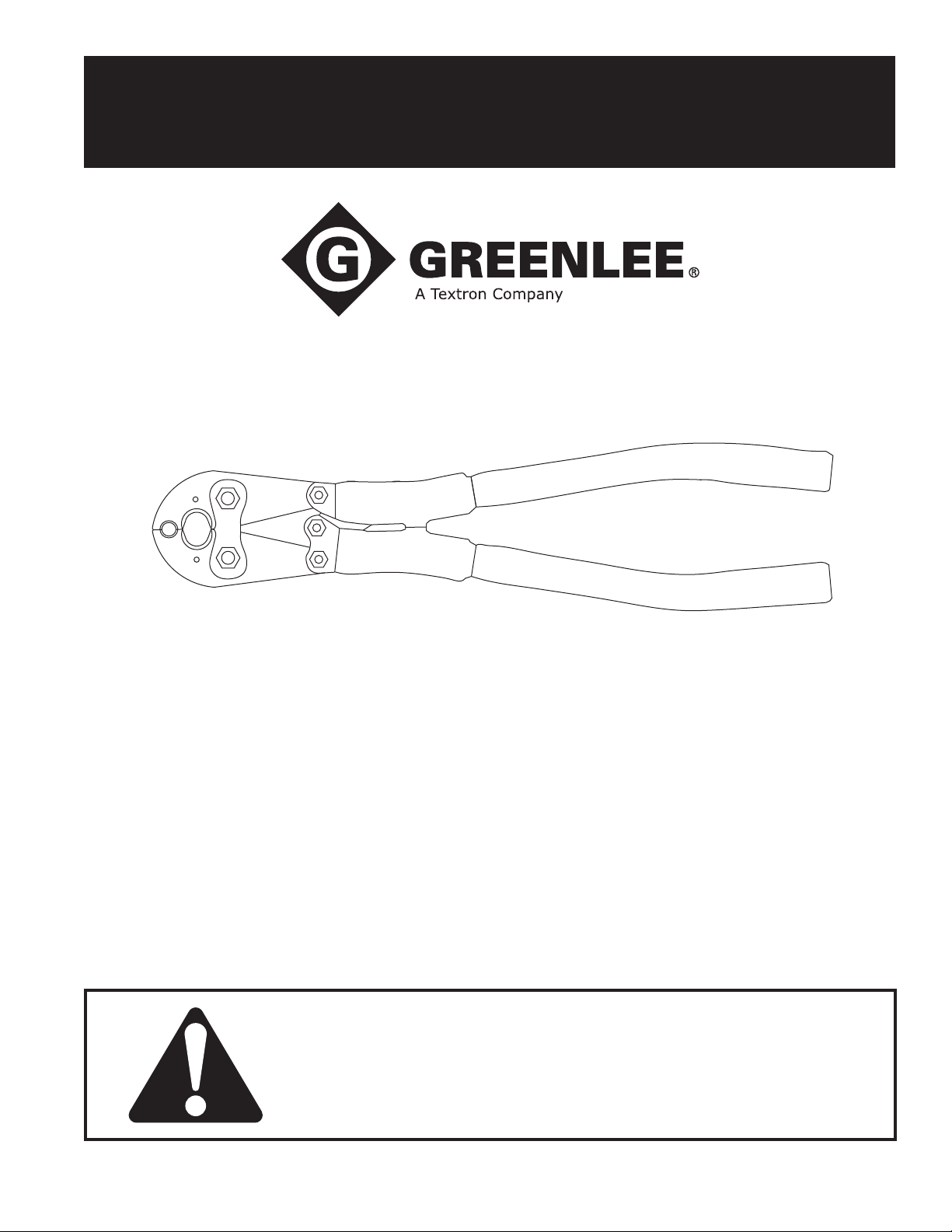
K425BG, K425O,
K425K58, and K425KO
Mechanical Crimping Tools
Read and understand all of the instructions and
safety information in this manual before operating
or servicing this tool.
Register this product at www.greenlee.com
99937573 REV 4 © 2015 Greenlee Textron Inc. 6/15
Page 2
K425BG, K425O, K425K58, and K425KO Mechanical Crimping Tools
Description
The K425BG and K425O Mechanical Crimping Tools
are hand-operated tools that use permanent die
grooves and/or insertable W-type dies. These tools
have two permanent die grooves, either a “BG” or “O”,
and a “D3” for distribution tap connectors. The “D3”
groove also serves as a seat for W-type die inserts to
install additional connector types. The die inserts snap
into a permanent “D3” groove easily with one hand and
are secured with the spring-loaded, positive lock, die
retaining buttons.
The K425K58 and K425KO Mechanical Crimping Tools
are hand-operated tools that use permanent die grooves
and/or insertable Kearney O-type dies. These tools have
two permanent die grooves, either a “5/8” or “O”, and
an opening for Kearney O-type dies. When used with
the Kearney “D” die, the die groove also serves as a
seat for W-type die inserts to install additional connector types. The die inserts snap into the “D” groove easily
with one hand and are secured with the spring-loaded,
positive lock, die retaining buttons.
All the tools install a full range of connectors including
service entrance splices and terminals, stacking lugs,
street light, stirrup, and repair sleeves.
The tools incorporate an over center toggle action
mechanism, allowing for easy crimping operations and
eld adjustability.
For use on:
• Copper taps from #10 solid to #2/0 stranded
• Aluminum/ACSR taps from #14 solid to #4/0 ACSR
• Stirrups from #6 AWG to #4/0 ACSR
• Copper and aluminum code conductor connectors
from #6 AWG to #4/0 stranded
• Overhead full tension deadend, full and non-tension
splices and terminals from #10 stranded to #4/0
ACSR
• 5/8" and .840" service entrance sleeves
Safety
Safety is essential in the use and maintenance of
Greenlee tools and equipment. This manual and any
markings on the tool provide information for avoiding
hazards and unsafe practices related to the use of this
tool. Observe all of the safety information provided.
IMPORTANT SAFETY INFORMATION
Electric shock hazard:
This tool is not insulated. Do not use
on live circuits.
Contact with live circuits could result
in severe injury or death.
An incomplete crimp can cause a re.
Use proper connector and cable combinations.
Improper combinations can result in an incomplete
crimp.
Failure to observe this warning could result in
severe injury or death.
Wear eye protection when operating
or servicing this tool.
Failure to wear eye protection could
result in serious eye injury from
ying debris.
• This tool is intended for two-handed operation.
Maintain a rm grip on both handles when using
this tool.
• Inspect tool before use. If any parts are worn
or damaged, send the tool to an authorized
Greenlee service center.
• Do not perform any service or maintenance other
than as described in this manual.
• Do not exceed the rated capacity of this tool.
Failure to observe these precautions may result in
injury or property damage.
Purpose of this Manual
This manual is intended to familiarize all personnel with
the safe operation and maintenance procedures for the
following Greenlee tools:
K425BG, K425O, K425K58, and K425KO
Mechanical Crimping Tools
Keep this manual available to all personnel.
Replacement manuals are available upon request at no
charge at www.greenlee.com.
Greenlee / A Textron Company 4455 Boeing Dr. • Rockford, IL 61109-2988 USA • 815-397-7070
All specications are nominal and may change as design
improvements occur. Greenlee Textron Inc. shall not be liable for
damages resulting from misapplication or misuse of its products.
KEEP THIS MANUAL
2
Page 3
K425BG, K425O, K425K58, and K425KO Mechanical Crimping Tools
Specifications
Crimp Force Developed ..................... 9,000 lb (4,091 kg)
Weight (tool only) ........................................... 6 lb (2.7 kg)
Operation
K425BG and K425O Die Selection
• For the K425BG, the upper opening is a “BG” die.
• For the K425O, the upper opening is an “O” die.
• For both the K425BG and K425O tools, the lower
opening is a “D3” die.
• Interchangeable dies may be used in the lower die
opening. Dies that may be used include:
— Greenlee KD6 series
— Burndy W and X series
— ILSCO ND series
— Huskie HT58 series
— Panduit CD-2001 series
— Other industry W-type dies
K425K58 and K425KO Die Selection
• For the K425K58, the upper opening is a “5/8” die.
• For the K425KO, the upper opening is an “O” die.
• For both the K425K58 and K425KO tools, the lower
opening accepts interchangeable Kearney O-type,
T&B 6-ton, and Blackburn “OD” dies.
• When used with Kearney O-type “D” die, additional
interchangeable dies that may be used include:
— Greenlee KD6 series
— Burndy W and X series
— ILSCO ND series
— Huskie HT series
— Panduit CD-2001 series
— Other industry W-type dies
Operation Procedure
1. Select the proper dies for the connector to be
crimped.
2. Install dies in jaws making certain that they are
properly secured by the spring-loaded, positive
lock, die buttons.
4. Operate the tool by closing, and allowing, the
handle butt/stop blocks to touch. Normally a “pop”
will be heard as the tool goes over center after the
crimp is made.
5. Continue crimping the connector until the correct
number of crimps have been completed. Work from
the center to the outer edges for splices and “H”
frame connectors, alternating sides if possible, for
the best compression connection.
6. Reposition tool for next crimp, if required. Unless
non-bowing dies are used, it is recommended that
the tool be rotated 90° for each adjacent crimp on
large splice connections.
Inspection and Adjustment
Check tools periodically for correct adjustment. As with
any tool, a slight amount of wear may occur over time.
This wear may be corrected by readjusting the tool as
follows:
1. Remove any die inserts from the tool and make sure
the jaw tips are free of dirt, etc.
2. Open tool and close handles until jaw tips just
touch. DO NOT CLOSE HANDLES COMPLETELY!
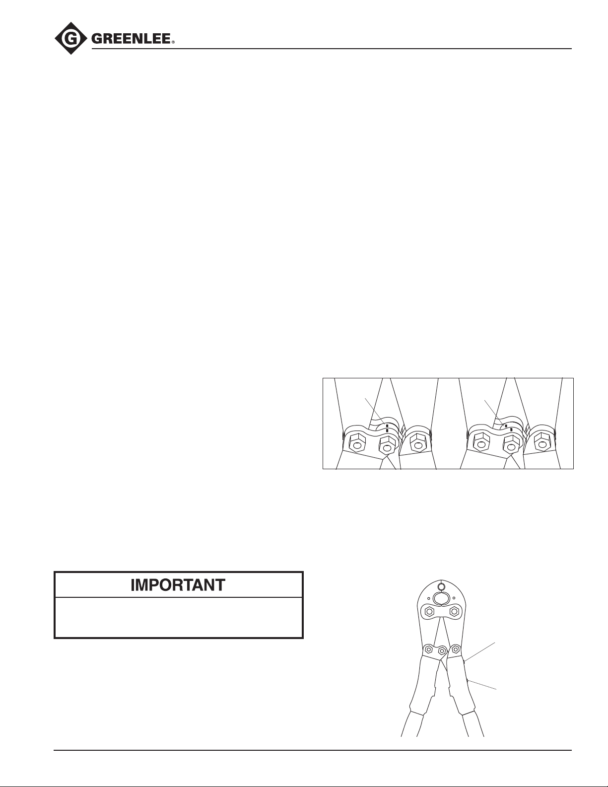
3. Check that the index marks (red grooves) on the
toggle link and frame line up.
Correct
4. If the marks line up, the tool is in proper adjustment.
5. If the marks do not line up, loosen the locking set
screw using a 1/4" (6.4 mm) hex key, and then turn
the adjustment screw clockwise or counterclockwise until the marks line up.
6. Tighten the locking set screw securely; the tool is
now properly adjusted and ready for use.
Adjustment
required
To help minimize hand and arm fatigue and perceived handle force during use, hold the crimping
tool with your hands at the end of the handles.
3. Insert conductor into the connector and align the
tool and die on the connector. Start in the center for
splices and “H” frames, and on the end, nearest the
pad, for terminals.
Greenlee / A Textron Company 4455 Boeing Dr. • Rockford, IL 61109-2988 USA • 815-397-7070
3
Adjusting
Set Screw
Locking
Set Screw
Page 4
K425BG, K425O, K425K58, and K425KO Mechanical Crimping Tools
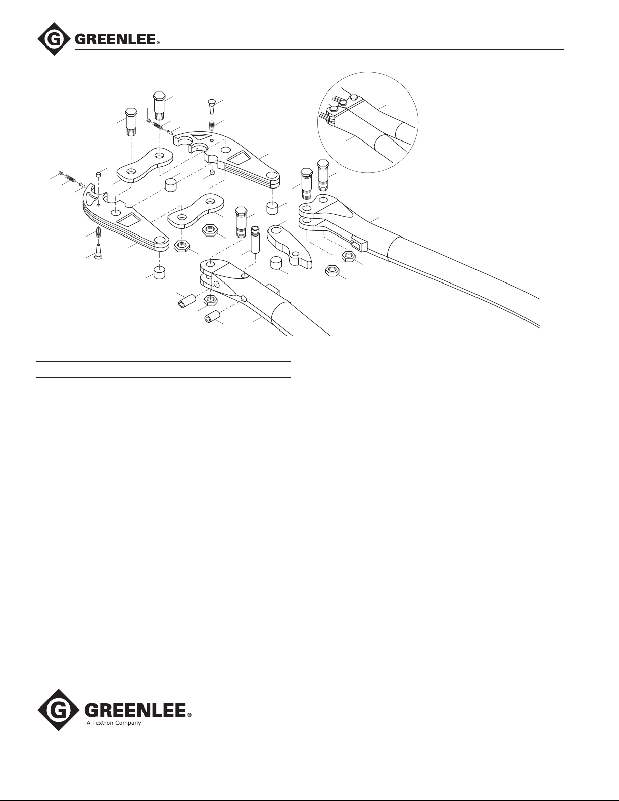
Illustration and Parts List
16
20
8
19
6
15
21
8
5
21
20
19
Key Description Qty
1 Jaw (K425BG) ............................................................. 2
Jaw (K425O) ............................................................... 2
Jaw (K425K58) ........................................................... 2
Jaw (K425KO) ............................................................. 2
2 Bushing, oil free .......................................................... 3
3 Spring, ø 6 x L10.8 ..................................................... 2
4 Pin, push .................................................................... 2
5 Nut .............................................................................. 2
6 Spindle .......................................................................1
7 Link ............................................................................. 2
8 Bolt, shoulder ............................................................. 2
9 Nut, lock 1/2-20 .......................................................... 2
10 Head, handle (A) .........................................................1
11 Head, handle (B) .........................................................1
12 Toggle .........................................................................1
13 Pin, drive ..................................................................... 1
14 Bolt, shoulder ............................................................. 3
15 Nut, lock 7/16-20 ........................................................3
16 Screw, 1/2-13 x 1 (1/4" hex skt, CP point) .................1
17 Screw, 1/2-13 x 3/4 (1/4" hex skt, CP point) ..............1
18 Tube, shrinkage .......................................................... 2
19 Pin, die retaining (K425K58 and K425KO)..................2
20 Spring (K425K58 and K425KO) ..................................2
21 Screw, set (K425K58 and K425KO) ............................2
7
3
1
4
2
4
3
1
5
7
9
9
17
13
10
14
14
18
18
14
2
12
2
15
11
15
Repair Kits
50021303 Kit, blade replacement (K425BG);
includes two of items 1–5, 7–9, and one of item 6
50021311 Kit, blade replacement (K425O);
includes two of items 1–5, 7–9, and one of item 6
52020877 Kit, blade replacement (K425K58);
includes two of items 1–5, 7–9, and one of item 6
52020879 Kit, blade replacement (K425KO);
includes two of items 1–5, 7–9, and one of item 6
50021370 Kit, plate replacement; includes two of items 7–9
50021486 Kit, handle-adjusting replacement;
includes one of items 10, 12–18
50021494 Kit, bolt-handle replacement;
includes three of items 2, 14, 15
50021508 Kit, pin-die replacement;
includes two of items 3–5
50021524 Kit, handle replacement; includes one
of items 11, 18, and two of items 14, 15
52021491 Kit, pin-Kearney die;
includes two each of items 19–21
4455 Boeing Drive • Rockford, IL 61109-2988 • USA • 815-397-7070
An ISO 9001 Company • Greenlee Textron Inc. is a subsidiary of Textron Inc.
www.greenlee.com
USA Tel: 800-435-0786
Fax: 800-451-2632
Canada Tel: 800-435-0786
Fax: 800-524-2853
International Tel: +1-815-397-7070
Fax: +1-815-397-9247
 Loading...