


MEM
INSTRUCTION MANUAL
CMGRT-100A
CLAMP-ON GROUND
RESISTANCE TESTER
~
6
A
0
0
0
4
V
C
V
I
A
T
SET-UP
MR
A
+ A
Ω
OFF
HOLD
52084187 REV 0
99 Washington Street
Melrose, MA 02176
Phone 781-665-1400
Toll Free 1-800-517-8431
Visit us at www.TestEquipmentDepot.com
© 2018 Greenlee Textron
01/18

Table of Contents
Description .............................................................................................................3
Safety .....................................................................................................................3
Purpose...................................................................................................................3
Important Safety Information..............................................................................4–6
Identification ...........................................................................................................7
Symbols on Unit ..............................................................................................7
Display Icons ..........................................................................................................8
Product Features ..............................................................................................9–22
Rotary Switch Positions ..................................................................................9
Alarm Feature and Set-up .............................................................................10
Navigation .....................................................................................................10
Set-up Menus ..........................................................................................11–19
Memory .........................................................................................................22
Auto-Power Off ..............................................................................................22
Measurement Mode ......................................................................................22
Theory of Operation ..............................................................................................23
Operation ..............................................................................................................24
Typical Applications ........................................................................................25–27
Frequently Asked Questions .................................................................................28
Accuracy .........................................................................................................28–29
Specifications .......................................................................................................30
Overvoltage Installation Categories ......................................................................30
Maintenance .........................................................................................................31
Battery Replacement ............................................................................................31
2

CMGRT-100A
Description
The Greenlee CMGRT-100A Clamp-On Ground Resistance Tester is a hand-held testing device intended to
evaluate grounding systems. It has two modes:
• Standard Mode: Standard Loop Resistance & Leakage Current Measurements
• Advanced Mode: Refine Measurements to find Impedance at the Selected Frequency & to compute
Contact Voltage
Furthermore, it can also give an idea about the integrity of the ground systems, the quality of connections or
bonds within the system.
The tester can measure Loop Resistance in the range of 0.01 Ω to 1500 Ω as well as leakage current in the
range of 0.2 mA to 40A. It comes with a data storage function, that can log up to 300 measurements (Both
Ω and/or A). Furthermore, the meter also allows the user to select test frequency between 50, 60, 128,
or 2083 Hz.
Safety
Safety is essential in the use and maintenance of Greenlee tools and equipment. This instruction manual and
any markings on the tool provide information for avoiding hazards and unsafe practices related to the use of
this tool. Observe all of the safety information provided.
Purpose
This instruction manual is intended to familiarize all personnel with the safe operation and maintenance
procedures for the Greenlee CMGRT-100A Clamp-On Ground Resistance Tester.
Keep this manual available to all personnel.
Replacement manuals are available upon request at no charge.
Greenlee and are registered trademarks of Greenlee Textron.
Do not discard this product or throw away!
For recycling information, go to www.greenlee.com.
All specifications are nominal and may change as design improvements occur. Greenlee Textron Inc.
shall not be liable for damages resulting from misapplication or misuse of its products.
® Registered: The color green for electrical test instruments is a registered trademark of
TextronInnovations Inc.
KEEP THIS MANUAL
3

Important Safety Information
SAFETY ALERT SYMBOL
This symbol is used to call your attention to hazards or unsafe practices which could result in an
injury or property damage. The signal word, defined below, indicates the severity of the hazard. The
message after the signal word provides information for preventing or avoiding the hazard.
Immediate hazards which, if not avoided, WILL result in severe injury or death.
Hazards which, if not avoided, COULD result in severe injury or death.
Hazards or unsafe practices which, if not avoided, MAY result in injury or property damage.
Read and understand this material before operating or servicing this
equipment. Failure to understand how to safely operate this tool can result in
an accident causing serious injury or death.
Electric shock hazard:
Contact with live circuits can result in severe injury or death.
4

CMGRT-100A
Important Safety Information
Electric shock and fire hazard:
• Do not expose this unit to rain or moisture.
• Do not use the unit if it is wet or damaged.
• Clamp meter, test leads or any other clamp accessory, when used to make a measurement, create a System.
The System is rated for CAT IV 600 VAC when using the test leads or accessories provided with the meter.
The System CAT and voltage rating is limited by the lowest rated component in the System when using test
leads or accessories not provided with the meter.
• Inspect the test leads or accessory before use. They must be clean and dry, and the insulation must be in
good condition. Do not use the test lead if the contrasting inner layer of insulation is visible.
• Use this unit for the manufacturer’s intended purpose only, as described in this manual. Anyotheruse can
impair the protection provided by the unit.
Failure to observe these warnings could result in severe injury or death.
Electric shock hazard:
• Do not operate with the case open.
• Before opening the case, remove the test leads from the circuit and shut off the unit.
• Keep hands and fingers below the barriers on the test leads and the clamp meter body.
Failure to observe these warnings could result in severe injury or death.
5

Important Safety Information
Electric shock hazard:
• Unless measuring voltage, current, or frequency, shut off and lock out power. Make sure that all capacitors
are discharged. Voltage must not be present.
• Set the selector and connect the test leads so that they correspond to the intended measurement. Incorrect
settings or connections can result in incorrect measurements or damage to the unit.
• Using this unit near equipment that generates electromagnetic interference can result in unstable or inaccurate readings.
Failure to observe these warnings could result in severe injury or death.
Electric shock hazard:
• Do not change the measurement function while the test leads are connected to a component or circuit.
• Do not clamp the jaw around a conductor carrying a frequency greater than 400Hz. The magnetic circuitry
may reach a hazardous temperature if this frequency is exceeded.
Failure to observe these precautions may result in injury and can damage the unit.
Electric shock hazard:
• Do not attempt to repair this unit. It contains no user-serviceable parts.
• Do not expose the unit to extremes in temperature or high humidity. Refer to “Specifications.”
Failure to observe these precautions may result in injury and can damage the unit.
6

Identification
1. Jaw
2. Guard
3. Lever
4. Rotary Switch
5. Display Backlight ON/OFF
6. Stores Measurements in Memory
7. Navigate/Validate Measurement Displays
8. HOLD Button
9. OLED Display
10. Calibration Loop (52084190)
1
2
3
4
5
6
7
8
9
CMGRT-100A
~
6
A
0
0
0
4
V
C
V
I
A
T
SET-UP
MR
A
+ A
Ω
OFF
MEM
HOLD
10
Symbols on the Unit
Warning—Read the
instruction manual
Warning—Risk of Electric Shock
Double insulation
Application around or removal from
hazardous live conductors is permitted
Recyclable in accordance with
ISO 14040 standard
7

Display Icons
11. Advance Mode
12. Inductive Component = Resistive Component (Advanced Mode)
13. Main Display. Displays OR (Out of Range) when the measured
resistance is over 1500 Ω or/and when the measured current is over 40A
14. Resistance/Impedance (Advanced Mode)
15. Storage Mode
16. Memory Recall Mode
17. Memory Location
18. Hazardous Voltage (Blinks when Voltage exceeds 50V)
19. Alarm Threshold High/Low Indicator
20. Alarm Threshold Display
21. Units of Alarm Displayed
22. Units of Main Display
23. Units of Top Display (Loop Inductance/ Current)
24. Top Display (Advanced Mode)
25. Low Battery
26. Auto Power Off Disabled
27. Open Jaw
28. Presence of Stray Noise (Current) In Loop
(Measurements not valid)
29. Main Display Indicates Date When Lit
30. Freeze Measurement
31. Speaker Enabled
30
2829
25
11
12
13
14
15
8
163117
18
1927202621
24
23
22

Product Features
Rotary Switch Positions:
OFF – Instrument Powered Off
Ω + A – Measure Loop Impedance & Leakage Current
A – Measure Current
MR – Display Stored Data
SET-UP – Access to Instrument settings & Data Selection
MEM
6
0
0
V
C
V
I
A
T
SET-UP
MR
A
+ A
Ω
OFF
CMGRT-100A
~
A
0
4
HOLD
Alarm Feature:
There are four distinct patterns of audio signal being employed for various warnings and instrument
operations. They can be disabled if required. The different pattern and their purposes are listed below:
Low – pitched with short intervals:
Normal instrument operations
Low – pitched with a permanent signal:
Alarm thresholds triggered for either Ω or A
High – pitched with a short intervals:
Irregular occurrence which may include OR in measurements or a full memory
High – pitched with a permanent signal:
Alarm threshold for V triggered
Thresholds are user defined values. The alarm is enabled with a user defined threshold when or when
icons are displayed.
– Alarm Enabled for measurement above defined threshold
– Alarm Enabled for measurement below defined threshold
9
Product Features (cont'd)
Instrument SET-UP
There are twelve accessible menus in the SET-UP position of the rotary switch that allows user defined
parameters to configure the instrument.
No. Function
1 Erase stored data.
2 Enables/ disable audible alarm.
3 Enables/disables Auto Power OFF
4 Sets the impedance alarm threshold (Ω)
5 Sets the voltage alarm threshold (V)
6 Sets the current alarm threshold (I)
7 Sets the date.
8 Sets the time.
9 Selects the Standard or Advanced operating mode.
10 Selects the test frequency for the impedance.
11 Enables/disables the AUTO-HOLD mode.
12 Displays the version number.
13 Not used.
Navigation
Navigating through the features is made possible using the following buttons on the instrument:
– Move up in the menu tree
– Move down in the menu tree
– Select menu or return to previous menu
When the user enters the menu tree, the selected menu starts blinking, indicating the state of the menu.
10

Product Features (cont'd)
SET-UP Menus
1. CLr – Erase Stored Data
• Enter menu by . CLr blinks.
• Hold and buttons simultaneously for 6 seconds to erase all recorded data.
The meter indicates MEM 0.
• Return to the previous menu by .
CMGRT-100A
SET-UP
MR
A
+ A
OFF
MEM
HOLD
2. SNd – Enable/Disable Audible Alarm
• Enter menu by . SNd blinks.
• Press or to enable/disable alarm sound.
• Alarm enabled when icon is visible and disabled when it is masked.
• Return to the previous menu by .
SET-UP
MR
A
+ A
OFF
MEM
HOLD
SET-UP
MR
A
+ A
OFF
HOLD
MEM
SET-UP
MR
A
+ A
OFF
HOLD
MEM
SET-UP
MR
A
+ A
OFF
MEM
MEM
HOLD
SET-UP
MR
A
+ A
OFF
HOLD
11

Product Features (cont'd)
3. stOP – Enable/Disable Auto Power OFF
• Enter menu by . stOP blinks.
• Press or to enable/disable Auto Power OFF.
• Auto Power OFF deactivated when icon is displayed.
• Return to the previous menu by .
SET-UP
MR
A
+ A
OFF
MEM
HOLD
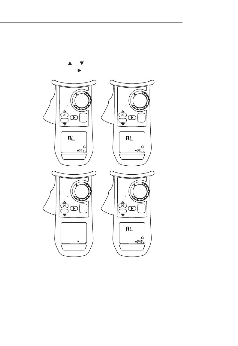
4. AL. Ω – Impedance Alarm Threshold
• Enter menu by . AL. Ω blinks.
• Press or to select state of the alarm:
— Disabled
— Enabled for a measurement exceeding the threshold
— Enabled for a measurement below the threshold
• Validate by .
SET-UP
MR
A
+ A
OFF
MEM
HOLD
SET-UP
MR
A
+ A
OFF
MEM
SET-UP
MR
A
+ A
OFF
MEM
HOLD
HOLD
SET-UP
MR
A
+ A
OFF
MEM
HOLD
12
Product Features (cont'd)
4. AL. Ω – Impedance Alarm Threshold (cont'd)
Setting the Alarm Value:
• Press or to select the impedance alarm threshold
• Validate by .
CMGRT-100A
SET-UP
MR
A
+ A
OFF
MEM
HOLD
SET-UP
MR
A
+ A
OFF
MEM
HOLD
SET-UP
MR
A
+ A
OFF
MEM
HOLD
SET-UP
MR
A
+ A
OFF
MEM
HOLD
13

Product Features (cont'd)
5. AL. V – Voltage Alarm Threshold
• Enter menu by . AL. V blinks.
• Press or to select state of the alarm:
— Disabled
— Enabled for a measurement exceeding the threshold
• Validate by .
Note: Voltage Alarm can only be triggered for measurements exceeding threshold
• Enter the menu tree further to select an alarm threshold and return to main menu
Setting the Alarm Value:
• Press or to select the impedance alarm threshold
• Validate by .
SET-UP
MR
A
+ A
OFF
MEM
HOLD
SET-UP
MR
A
+ A
OFF
MEM
HOLD
SET-UP
MR
A
+ A
OFF
MEM
HOLD
SET-UP
MR
A
+ A
OFF
MEM
HOLD
SET-UP
MR
A
+ A
OFF
MEM
HOLD
SET-UP
MR
A
+ A
OFF
MEM
HOLD
14
Product Features (cont'd)
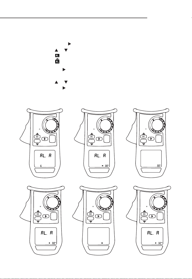
6. AL. A – Current Alarm Threshold
• Enter menu by . AL. A blinks.
• Press or to select state of the alarm:
— Disabled
— Enabled for a measurement exceeding the threshold
• Validate by .
Setting the Alarm Value:
• Press or to select the impedance alarm threshold
• Validate by .
Note: Current Alarm can only be triggered for measurements exceeding threshold
• Enter the menu tree further to select an alarm threshold and return to main menu
CMGRT-100A
SET-UP
MR
A
+ A
OFF
MEM
HOLD
SET-UP
MR
A
+ A
OFF
MEM
HOLD
SET-UP
MR
A
+ A
OFF
MEM
MEM
HOLD
SET-UP
MR
A
+ A
OFF
HOLD
SET-UP
MR
A
+ A
OFF
MEM
HOLD
SET-UP
MR
A
+ A
OFF
MEM
HOLD
15

Product Features (cont'd)
7. dAtE – Set Date
• Enter menu by . dAtE blinks.
• Press or to select a year and validate by .
• Press or to select the month and validate by .
• Press or to select the date.
• Validate and return to the previous menu by .
SET-UP
MR
A
+ A
OFF
MEM
HOLD
SET-UP
MR
A
+ A
OFF
MEM
HOLD
SET-UP
MR
A
+ A
OFF
MEM
MEM
HOLD
SET-UP
MR
A
+ A
OFF
HOLD
SET-UP
MR
A
+ A
OFF
MEM
MEM
HOLD
SET-UP
MR
A
+ A
OFF
HOLD
16

Product Features (cont'd)
7. dAtE – Set Date (cont'd)
CMGRT-100A
SET-UP
MR
A
+ A
OFF
MEM
HOLD
8. HOUR – Set Time
• Enter menu by . HOUR blinks.
• Press or to select AM/PM or a 24-hour display mode (24H), which blinks.
Validate by .
• Press or to select the hour, which blinks. Validate by .
• Press or to select the minutes value, which blinks. Validate by .
• Validate and return to the previous menu by .
SET-UP
MR
A
+ A
OFF
MEM
HOLD
SET-UP
MR
A
+ A
OFF
MEM
MEM
HOLD
SET-UP
MR
A
+ A
OFF
HOLD
SET-UP
MR
A
+ A
OFF
MEM
HOLD
17

Product Features (cont'd)
8. HOUR – Set Time (cont'd)
SET-UP
MR
A
+ A
OFF
MEM
MEM
HOLD
SET-UP
MR
A
+ A
OFF
HOLD
SET-UP
MR
A
+ A
OFF
MEM
MEM
HOLD
SET-UP
MR
A
+ A
OFF
HOLD
SET-UP
MR
A
+ A
OFF
MEM
MEM
HOLD
SET-UP
MR
A
+ A
OFF
HOLD
18

Product Features (cont'd)
9. USE – Select Standard/Advanced Mode
• Enter menu by . USE blinks.
• Press or to select between Standard or Advanced Mode.
— Advanced Mode: The + icon is displayed
— Standard Mode: Std is displayed
• Validate and return to the previous menu by .
CMGRT-100A
SET-UP
MR
A
+ A
OFF
MEM
MEM
HOLD
SET-UP
MR
A
+ A
OFF
HOLD
SET-UP
MR
A
+ A
OFF
MEM
MEM
HOLD
SET-UP
MR
A
+ A
OFF
HOLD
SET-UP
MR
A
+ A
OFF
MEM
HOLD
19

Product Features (cont'd)
10. FrEQ – Select Test Frequency
• Enter menu by . FrEQ blinks.
• Press or to select among the four available transposition frequencies for
measured impedance
• Validate and return to the previous menu by .
SET-UP
MR
A
+ A
OFF
MEM
MEM
HOLD
SET-UP
MR
A
+ A
OFF
HOLD
SET-UP
MR
A
+ A
OFF
MEM
MEM
HOLD
SET-UP
MR
A
+ A
OFF
HOLD
SET-UP
MR
A
+ A
OFF
MEM
MEM
HOLD
SET-UP
MR
A
+ A
OFF
HOLD
20

Product Features (cont'd)
11. HOLd – Enable/Disable AUTO-HOLD
• Enter menu
• Use movement buttons to enable or disable AUTO-HOLD. It is enabled when
icon is displayed
CMGRT-100A
SET-UP
MR
A
+ A
OFF
MEM
HOLD
SET-UP
MR
A
+ A
OFF
MEM
HOLD
SET-UP
MR
A
+ A
OFF
MEM
HOLD
SET-UP
MR
A
+ A
OFF
MEM
HOLD
SET-UP
MR
A
+ A
OFF
MEM
HOLD
21

Product Features (cont'd)
12. VER – Display Version Number
• Enter menu and the version number is displayed
SET-UP
MR
A
+ A
OFF
MEM
HOLD
SET-UP
MR
A
+ A
OFF
MEM
HOLD
SET-UP
MR
A
+ A
OFF
MEM
HOLD
13. CAL – Reserved for Factory Use
Memory:
The instrument can store up to 300 measurements. A full memory is represented by FULL. A data can be
stored by pressing the button. Storage is confirmed with an audible sound.
Switch rotary switch to to display stored data.
Auto Power OFF:
Auto Power OFF can be enabled/disabled in SET-UP. If enabled the instrument remains powered on for
exactly 5 minutes, when inactive, until it automatically powers off to save/extend battery life.
Measurement Modes:
1. Standard Mode – Only one measurement screen is available. The loop impedance and the
leakage current is displayed. Measurement frequency is 2083 Hz.
2. Advanced Mode – Three measurements screens are available.
• Screen 1 displays the same as Standard Mode. However, the loop impedance at the
other frequencies can be displayed using SET-UP.
• Screen 2 displays the contact voltage calculated using the loop impedance and
current measurement.
• Screen 3 displays loop resistance (R) and loop inductance (L) In case of a negligible
inductive component, the symbol R=L is displayed
22

CMGRT-100A
V
I
= Rx + Rx »
1
1
Ri
n
i=1
Σ
1
1
Ri
n
i=1
Σ
1
Ri
Σ
1
i=1Σ
1
1
Ri
n
i=1
Σ
1
1
Ri
n
i=1
Σ
Theory of Operation
The CMGRT-100A performs two measurements: resistance and current. It measures resistance by applying
a voltage at 2.403 kHz and indirectly measuring the resulting current. It measures current indirectly by
measuring the electromagnetic field around a conductor, which is proportional to the current flowing through
the conductor.
The following illustration and schematic diagram represent a typical multiple ground rod system.
The ground electrodes are represented by R (R1, R2, R3 … Rn), and the CMGRT-100A is represented
by ~
V.
The CMGRT-100A induces a voltage (V) into the system and measures the resulting current (I). The CMGRT100A then divides the voltage by the current to derive the resistance (V/I = R). The equation for the resistance
of Rx is shown below.
Rx R1 Rn-1 Rn
The equation shown above is the standard equation for finding the resistance of one leg of a parallel circuit.
However, the CMGRT-100A uses a simplified equation (V/I = Rx) since the rightmost section of
n
1
) is a very small amount of resistance if “n” is sufficiently large. This is shown
i=1
n
1
Rx = 25 Ω + 0.25 Ω Rx = 25.25 Ω
the formula (
mathematically in the example below.
Example: A grid with 101 ground electrodes, each with a resistance of 25 Ω.
The measured resistance, Rx, would equal the resistance of Rx in series with the parallel resistance of
the other 100 ground rods:
Rx = 25 Ω +
Note, however, that most grounded systems have more than 100 ground electrodes. Therefore, the parallel
resistance is negligible. It is practical to simplify the equation and the calculation to V/I = Rx.
where, usually
23

Operation
1. See Features.
2. Turn the unit on, selecting the appropriate features (turn the speaker on or off, change the alarm
setpoint, etc).
3. See Typical Applications for specific measurement instructions.
4. Test the unit on a known functioning circuit or the test resistance loop. To use the test resistance loop,
clamp the CMGRT-100A around the loop. It should read between 4.9 Ω and 5.1 Ω.
Note: This value is for ambient temperature between 20 °C and 25 °C (68 °F and 78 °F). It may differ a few
counts below or above this temperature.
• If the unit does not function as expected on a known functioning circuit or the test resistance loop,
replace the battery.
• If the unit still does not function as expected, send the unit to Greenlee for repair. See the address
shown under Warranty.
5. Take the reading(s) from the circuit or component to be tested.
• If the ground current exceeds 5 A or if the noise exceeds 50 V, the CMGRT-100A will not measure
the resistance accurately. Make a note of the location for maintenance and proceed to the next
test location.
• A reading of < 0.01 may indicate that the cable is part of a closed loop; for example; when two
bonding conductors are connected to the same enclosure and ground rod.
• A high resistance reading or OR (Out of Range) may indicate any of the following:
The cable is not grounded at both ends (a lack of a ground, or a lack of a path back to the
system neutral).
The ground rod is in poor condition.
The ground circuit is broken, or open.
The bonds on the rod or splices are of poor quality. Check for buried split butts, clamps, and
hammered-on connections.
A component in the circuit is causing high leakage.
6. After taking the measurements, make a written record of the data, if necessary (date, location,
resistance measurement, and current measurement).
24

CMGRT-100A
Typical Applications
General procedures for all applications:
1. Remove any molding from the ground conductor so that the jaws can close completely around the
conductor.
2. Center the conductor in the jaw for highest accuracy.
3. Take the reading.
4. Replace the molding.
Service Entrance or Meter
Water Pipe GroundMultiple Ground Rods
Service Meter
Building Wall
Service Box
Building Wall
Service Box
Service Meter
Water Pipe
Note: Clamp onto the conductor between the
service neutral and both grounded points.
25

Typical Applications (cont'd)
Central Office Locations
The main ground conductor from a ground window or a ground plane is usually the location to clamp the
unit. Due to the wiring practices within the central office, there are many locations at which you can look at
the water pipe or counterpoise from within the building. An effective location is usually at the ground bus in
the power room or near the backup generator.
By measuring resistance and current at several points and comparing the readings, you can identify neutral
loops, utility grounds, and central office grounds. The test is effective and accurate when the ground window
is connected to the utility ground at only one point.
Service Panel
At a service panel, several sources may be grounded at a single grounding point. As shown in the following
illustration, those sources could be electric neutral, telephone, CATV, and water.
The primary return path should be electric neutral. After taking the first measurement, disconnect one source
and take a new measurement. Continue in this manner until all other sources have been disconnected. Any
higher measurement may indicate that the electric neutral is defective or open.
Electric Utility
NEUTRAL
A B
WH
BK
Bare
240 VAC
120 VAC
Phone
CATV
GROUND BUS
Service Panel
Ground
Electrode
26
NEUTRAL BUS

Typical Applications (cont'd)
CMGRT-100A
Telephone Pedestal
Ground Bar
Sheath Connection
Ground Level
Ground Bar
Sheath Connection
Ground Level
Phone
Pedestal
Phone
Pedestal
Ground Rod
Note: Clamp onto the ground conductor (as shown) or onto the ground rod.
1
2
1. Remove ground bar connection to
pedestal rod.
2. Extend pedestal rod lead to the
ground bar using a temporary
jumper.
Above Telephone Space
Ground wire doubled
under ground clamp
Ground Rod
Note: Clamp onto the ground conductor (as
shown). The reading will indicate the
connection between the telephone circuit
ground and the power utility ground.
27

Frequently Asked Questions
Q: Does the ground electrode have to be disconnected and isolated as is required when using the “Fall-
Of-Potential” test with auxiliary electrodes?
A: No. Actually the electrode must be connected to the system to provide the path for test signal
injection as well as to provide the background impedance necessary as the reference. Additionally, if
the tested rod is poorly bonded to the ground connector, a high reading will be present.
Q: Does this mean I am not able to test an independent electrode?
A: No. However, as soon as the connection is made to a multiple electrode system, usually provided by
the connection to the system neutral, you can clamp on and make a measurement.
Q: Must the unit be clamped directly on the electrode?
A: No. The unit provides valid measurement results when clamped onto the electrode or the conductor
leading to the ground electrode. The reading through the conductor verifies not only the ground
electrode resistance, but also the connections of the ground wire to the rest of the system.
Q: Does the system under test have to be energized or de-energized to perform the test?
A: We are measuring the grounding network. The only requirements are that ground connections be
made to the system under test and that the voltage-to-ground at the tested point not exceed the
instrument rating.
Q: How does clamp-on ground testing compare with the standard “Fall-Of-Potential” test?
A: Empirical testing has validated that when performed correctly, both methods provide accurate and
repeatable readings for ground electrode resistance.
Q: How large a conductor can the jaw accommodate?
A: The inner diameter of the jaw is 35 mm (1.38") and can accommodate cables up to 1000 MCM.
Accuracy
Accuracy is specified as ± (a percentage of the reading + a fixed amount) within the following parameters:
• Temperature: 23 °C ± 3 °C (73.4 °F ± 9 °F)
• Relative humidity: 50% RH ± 10%
• Conductor location: Centered in jaw
• Battery charge: 6 V ± 0.2 V
• External magnetic field: < 40 A/m
• External electrical field: < 1 V/m
• Loop resistance: Non-inductive
28

Ground Resistance
Range Resolution Accuracy
0.010 to 0.10 Ω 0.001 Ω ± (1.5% + 0.01 Ω)
0.10 to 1.00 Ω 0.01 Ω ± (1.5% + 0.02 Ω)
1.0 to 50.0 Ω 0.1 Ω ± (1.5% + 0.1 Ω)
50.0 to 100.0 Ω 0.5 Ω ± (2.0% + 0.5 Ω)
100 to 200 Ω 1 Ω ± (3.0% + 1 Ω)
200 to 400 Ω 5 Ω ± (5.0% + 5 Ω)
400 to 600 Ω 10 Ω ± (10.0% + 10 Ω)
600 to 1200 Ω 50 Ω ± 20% (approximately)
1200 to 1500 Ω 50 Ω ± 25% (approximately)
Ground or Leakage Current
Measurement Range Resolution Accuracy
0.1 to 1.000mA 0.1µA ±2% ±50µA
1.000 to 3.000mA
3.00 to 10.00mA
10.00 to 30.00mA
30.0 to 100.0mA
100.0 to 300.0mA
0.300 to 1.000A
1.000 to 3.000A
3.00 to 39.99A
10µA ±2% ±50µA
100µA ±2% ±100µA
1mA ±2% ±1mA
10mA ±2% ±10mA
CMGRT-100A
Contact Voltage
Measurement Range Resolution Accuracy
0.1 to 5.0V 0.1V ±5% ±0.1V
5.0 to 50.0V 0.5V ±5% ±0.5V
50.0 to 75.0V 1V ±10% ±1V
29

Specifications
Display: 3-3/4–digit OLED (4000 counts)
Jaw Opening: 35 mm (1.38")
Resistance Measurement Frequency: 2083 Hz
Current Measurement Frequency: 47 Hz to 800 Hz
Automatic Power-Off: After 5 minutes of inactivity
Overvoltage Protection Categories:
Category IV, 600 VAC, Pollution Degree 2
Operating Conditions:
–20 °C to 55 °C (-4 °F to 131 °F), 10% to 90% relative humidity
Storage Conditions: –40 °C to 70 °C (–40 °F to 158 °F), 10 to 75% relative humidity
Remove battery
Battery: 4 x 1.5V LR6 (AA) alkaline or 4 NiMH batteries
Statement of Conformity
Greenlee Textron Inc. is certified in accordance with ISO 9001 (2000) for our Quality Management Systems.
The instrument enclosed has been checked and/or calibrated using equipment that is traceable to the
National Institute for Standards and Technology (NIST).
Overvoltage Installation Categories
These definitions were derived from the international safety standard for insulation coordination as it applies
to measurement, control, and laboratory equipment. These overvoltage categories are explained in more
detail by the International Electrotechnical Commission; refer to either of their publications:
IEC 1010-1 or IEC 60664.
Overvoltage Category I
Signal level. Electronic and telecommunication equipment, or parts thereof. Some examples include
transient-protected electronic circuits inside photocopiers and modems.
Overvoltage Category II
Local level. Appliances, portable equipment, and the circuits they are plugged into. Some examples include
light fixtures, televisions, and long branch circuits.
Overvoltage Category III
Distribution level. Permanently installed machines and the circuits they are hard-wired to. Some examples
include conveyor systems and the main circuit breaker panels of a building's electrical system.
Overvoltage Category IV
Primary supply level. Overhead lines and other cable systems. Some examples include cables, meters,
transformers, and other exterior equipment owned by the power utility.
30

Maintenance
• Do not attempt to repair this unit. It contains no user-serviceable parts.
• Do not expose the unit to extremes in temperature or high humidity. See Specifications.
Failure to observe these precautions can result in injury and can damage the unit.
Battery Replacement
Before opening the case, remove the jaw from the circuit and shut off the unit.
Failure to observe these warnings can result in severe injury or death.
The Model CMGRT-100A is powered by four 1.5V batteries. The battery
replacement indicator will blink when battery voltage is low and will
display continuously when battery replacement is required.
1. Unclamp the instrument and set rotary switch to OFF
2. Use a Phillips head screwdriver to remove the two screws to
uncover the batteries
3. Replace batteries as per specifications while observing polarities
4. Cover the battery Compartment and re-screw it before validating
instrument operation
CMGRT-100A
Cleaning
Periodically wipe the case with a damp cloth and mild detergent; do not use abrasives or solvents. If the
meter will not be used for periods longer than 60 days, remove the batteries and store them separately.
31
 Loading...