

Page 1
SERVICE MANUAL
H4635/49334
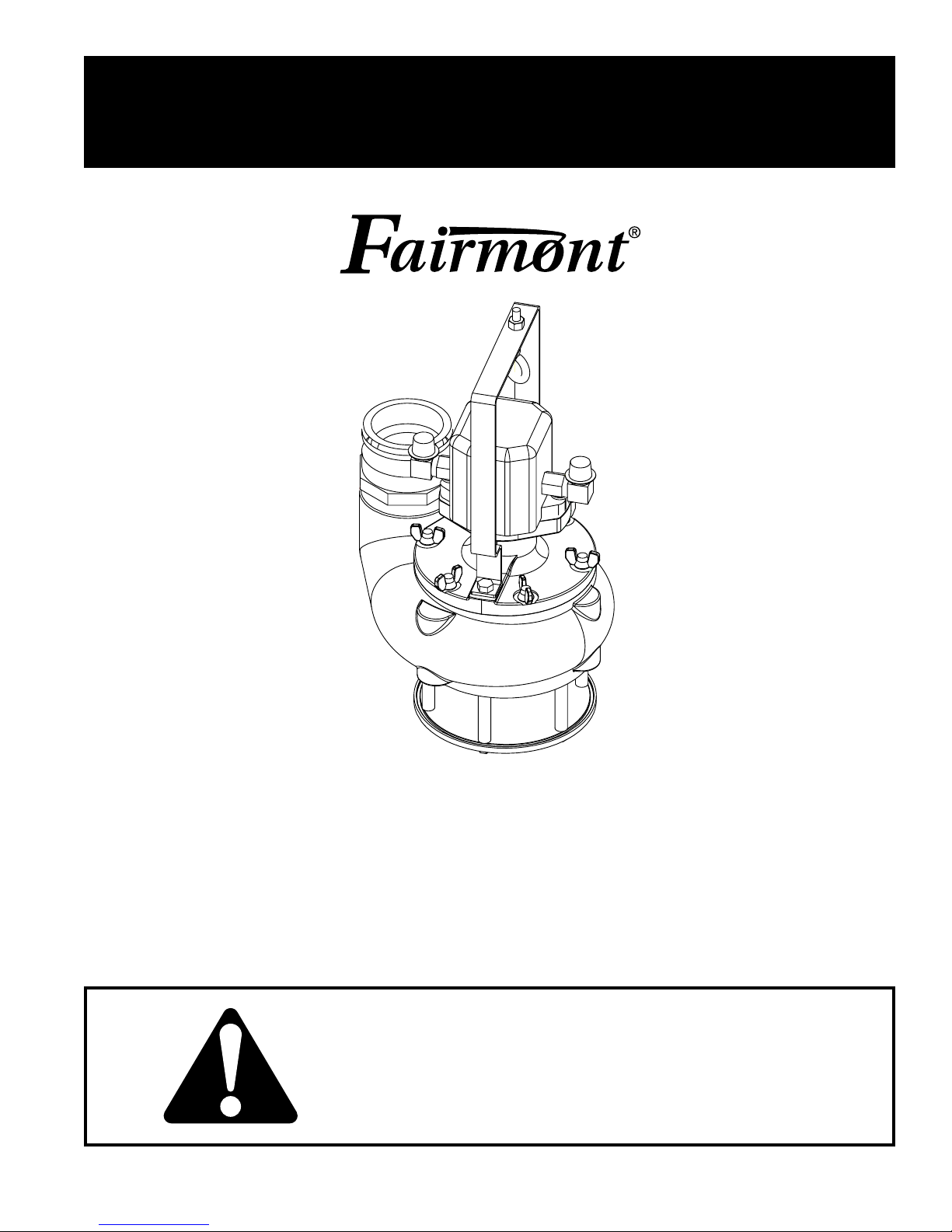
Submersible Trash Pump
999 2813.2 REV 2 © 2003 Greenlee Textron 6/03
Serial Code GKH
Read and understand all of the instructions and
safety information in this manual before operating
or servicing this tool.
Page 2

H4635 / 49334 Submersible Trash Pump
Table of Contents
Description .....................................................................2
Purpose..........................................................................2
Other Publications..........................................................2
Important Safety Information.......................................3-4
Disassembly................................................................... 5
Inspection....................................................................... 5
Assembly........................................................................6
Exploded Views and Parts Lists..................................... 7
Accessories.................................................................... 8
Safety
Safety is essential in the use and maintenance of
Fairmont tools and equipment. This manual and any
markings on the tool provide information for avoiding
hazards and unsafe practices related to the use of this
tool. Observe all of the safety information provided.
Purpose
This manual is intended to familiarize all personnel
with the safe service procedures for the H4635/49334
Submersible Trash Pump, serial code GKH. Keep this
manual available to all personnel.
Replacement manuals are available upon request
at no charge.
®
Loctite
is a registered trademark of Loctite Corporation.
Other Publications
Operation Manual: Publication 999 2815.9
Specifications and Parts Manuals:
H4630/49334: Publication 999 3045.5
SAE Standard J1273 (Hose and Hose Assemblies):
Publication 999 3032.3
Greenlee / A Textron Company 2 4455 Boeing Dr. • Rockford, IL 61109-2988 USA • 815-397-7070
All specifications are nominal and may change as design improvements occur. Greenlee Textron shall not be liable for damages
resulting from misapplication or misuse of its products.
Loctite is a registered trademark of Loctite Corporation.
KEEP THIS MANUAL
Page 3
H4635 / 49334 Submersible Trash Pump
IMPORTANT SAFETY INFORMATION
SAFETY
ALERT
SYMBOL
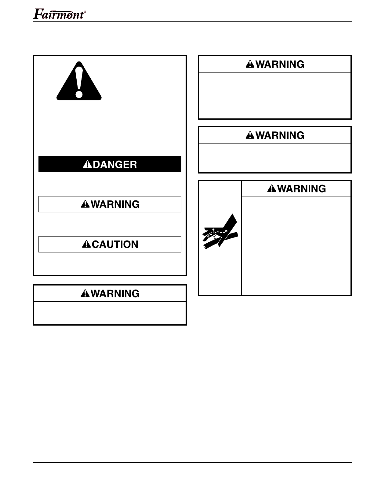
This symbol is used to call your attention to hazards
or unsafe practices which could result in an injury
or property damage. The signal word, defined below,
indicates the severity of the hazard. The message
after the signal word provides information for preventing or avoiding the hazard.
Immediate hazards which, if not avoided, WILL result
in severe injury or death.
Do not operate the pump if the impeller blades are
exposed. Do not operate the pump without the
base legs and base plate in place.
Failure to observe this warning can result in
severe injury or death.
Do not inspect, adjust, or clean tool when it is
connected to a power source. Accidental startup
can result in serious injury.
Hazards which, if not avoided, COULD result in severe
injury or death.
Hazards or unsafe practices which, if not avoided,
MAY result in injury or property damage.
Before operating this tool, see the safety information
and operating instructions in the Operation Manual.
Skin injection hazard:
Oil under pressure easily punctures
skin causing serious injury, gangrene or death. If you are injured by
escaping oil, seek medical attention
immediately.
• Do not use fingers or hands to
check for leaks.
• Do not hold hose or couplers while
operating the power source.
• Depressurize the hydraulic system
before servicing.
Greenlee / A Textron Company 3 4455 Boeing Dr. • Rockford, IL 61109-2988 USA • 815-397-7070
Page 4
H4635 / 49334 Submersible Trash Pump
IMPORTANT SAFETY INFORMATION
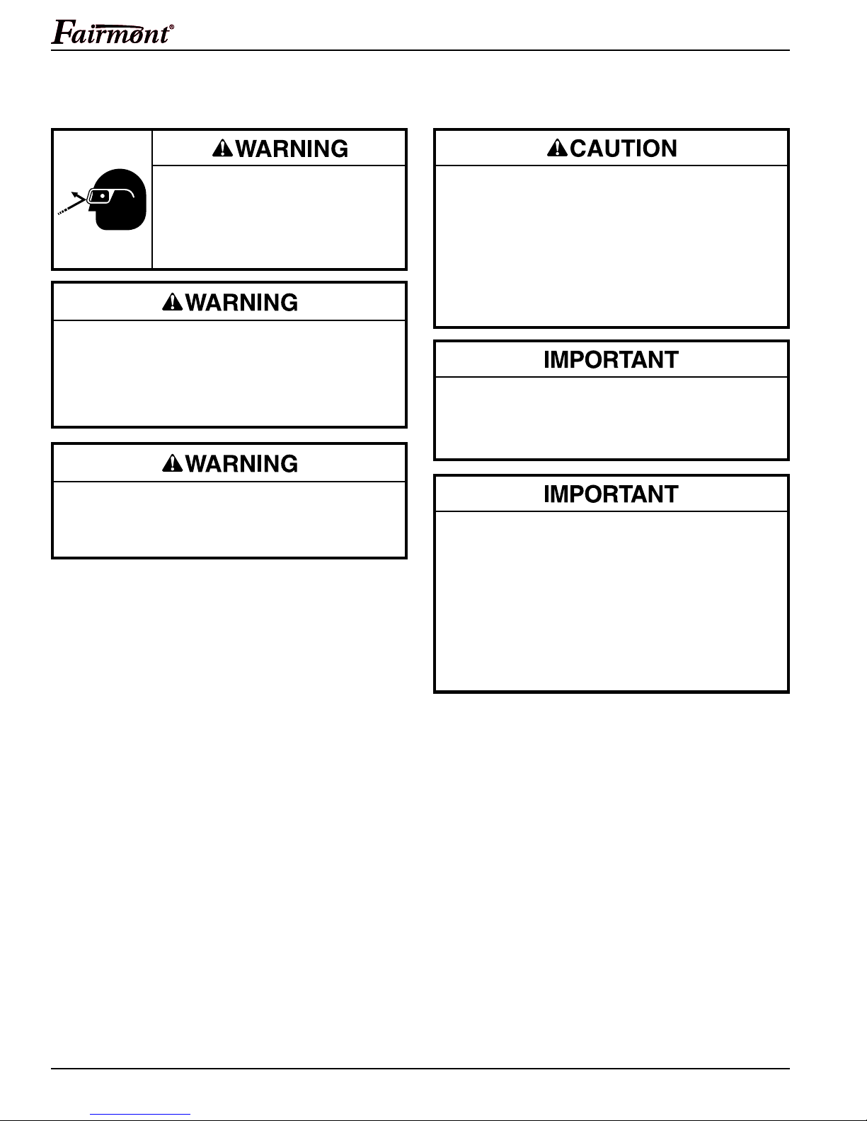
Wear eye protection when operating
or servicing this tool.
Failure to wear eye protection can
result in serious eye injury from
flying debris or hydraulic oil.
Do not exceed the maximum hydraulic flow,
pressure relief or back pressure listed in the
Specifications and Parts manual.
Failure to observe this warning can result in
severe injury or death.
Do not disconnect tool, hoses, or fittings while
the power source is running or if the hydraulic fluid
is hot. Hot hydraulic fluid can cause serious burns.
Hydraulic oil can cause skin irritation.
• Handle the tool and hoses with care to prevent
skin contact with hydraulic oil.
• In case of accidental skin contact with hydraulic
oil, wash the affected area immediately to remove
the oil.
Failure to observe these precautions can result
in injury.
Do not reverse hydraulic flow. Operation with
hydraulic flow reversed can cause tool malfunction.
Connect the supply (pressure) hose and return
(tank) hose to the proper tool ports.
Procedure for disconnecting hydraulic hoses, fittings
or components:
1. Move the flow lever on the hydraulic power
source to the OFF position.
2. Stop the power source.
3. Follow the sequence under Disconnecting Hoses
to prevent pressure buildup. In case some
pressure has built up, loosen hoses, fittings or
components slowly.
Greenlee / A Textron Company 4 4455 Boeing Dr. • Rockford, IL 61109-2988 USA • 815-397-7070
Note: Keep decals clean and legible. Replace decals
when necessary—see the decals listed in the Parts and
Specifications manual.
Page 5

H4635 / 49334 Submersible Trash Pump
Disassembly
Complete disassembly of the tool is not recommended.
If a complete overhaul is necessary, return the tool to your
nearest authorized Fairmont distributor or to Fairmont.
The disassembly procedure is divided into sections of
the tool. Disassemble only the section(s) necessary to
complete the repair.
Disassemble the tool on a flat, clean surface. Take care
not to lose or damage any parts that may fall free during
disassembly.
Base
1. Remove six cap screws (9), and lock washers (21).
2. Remove base (8), and bushings (20).
Discharge Coupling, Handle, and Cover
1. Remove discharge coupling (14) from housing (2),
if necessary.
2. Remove two cap screws (10) and lock washers (18).
Remove handle (5) from cover (4).
3. Remove six wing nuts (11). Remove cover (4)
from housing (2).
4. Remove six studs from housing (2), if necessary.
Impeller
1. Lock impeller (6) in place by inserting a screwdriver
between the blades. Remove cap screw (19) and
cone washer (3).
2. Unscrew the impeller (6) to remove from the drive
shaft (27).
Greenlee / A Textron Company 5 4455 Boeing Dr. • Rockford, IL 61109-2988 USA • 815-397-7070
Page 6
H4635 / 49334 Submersible Trash Pump
Assembly
Refer to the Exploded View(s) and Parts List for correct
orientation and placement of parts.
Replace any O-rings, V-rings, seals, and gaskets on
parts that have been disassembled. Apply hydraulic fluid
or O-ring lubricant to all O-rings and all metal surfaces
which they must slide over. When installing an O-ring
which must slide over sharp surfaces, use a rolling
motion and be careful not to damage the O-ring.
Wherever the assembly results in metal-to-metal
contact, coat the surfaces with hydraulic fluid or O-ring
lubricant.
When instructed to use a thread locking compound or
other adhesive product, follow the manufacturer's
instructions for curing.
.62" (15.7 mm)
Thread Length
1.00"
(25.4 mm)
Impeller
1. Apply an anti-seize compound to the threads of the
motor shaft. Install the impeller onto the drive shaft.
Tighten the impeller securely.
2. Apply Loctite® 242™ Threadlocker to the threads of
the cap screw (19). Install the cap screw and cone
washer (3) on the end of the motor shaft. Lock the
impeller blades by inserting a screwdriver between
the blades and tighten the cap screw.
Discharge Coupling, Handle and Cover
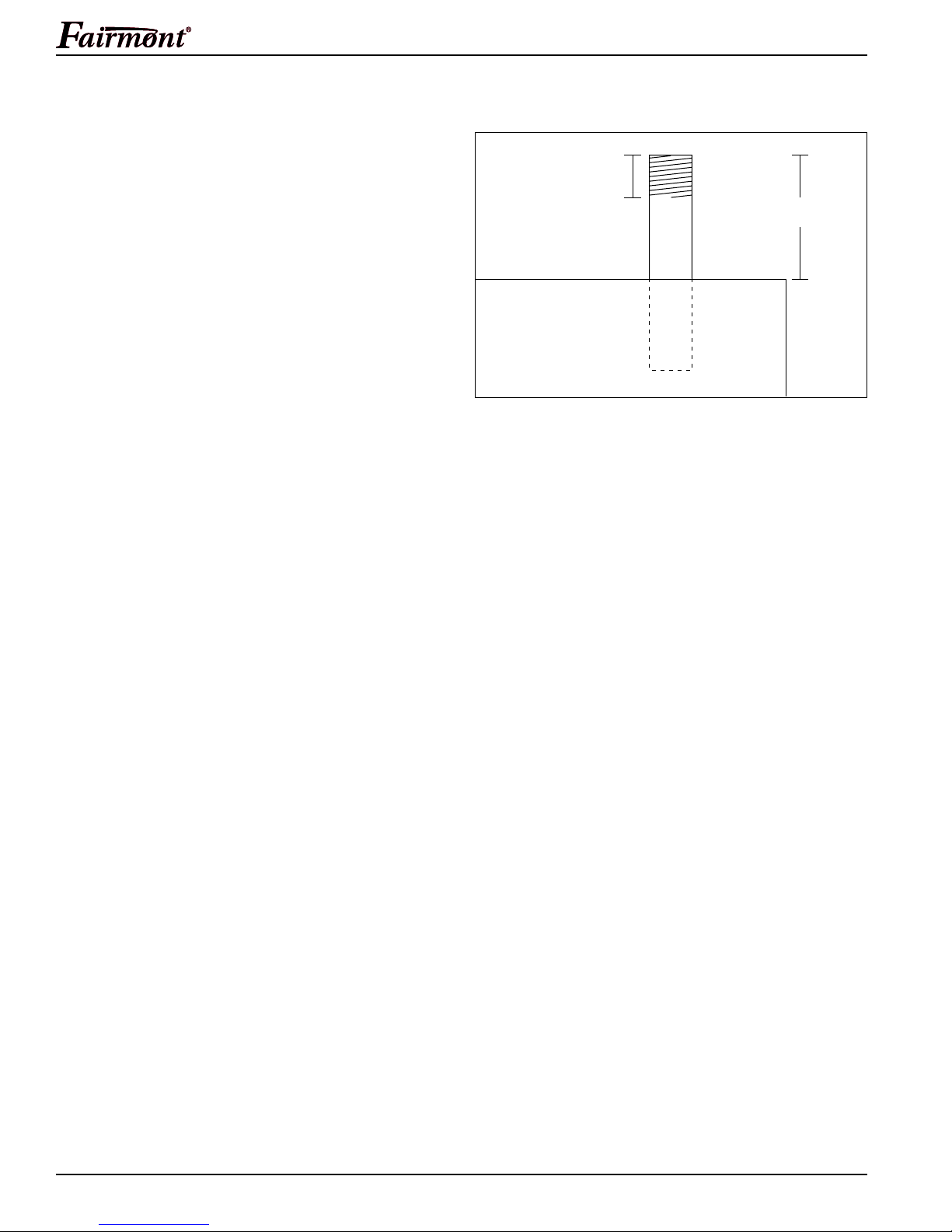
1. Apply Loctite® 271™ Threadlocker, or equivalent,
to the threads of the studs, if removed. Install six
studs so 1" of stud is exposed above the housing (2),
(see illustration). Follow the manufacturer’s instructions for curing. Assemble the cover (4) to the
housing (2) with six wing nuts (11).
2. Assemble the handle (5) to the cover (4) using two
cap screws (10) and lock washers (18).
3. Install the discharge coupling (14) to the housing (2),
if removed. Tighten securely.
Base
1. Position the housing upside down (with the suction
port upward). Place six bushings (20) over the six
threaded holes in the housing.
2. Position the base (8) (with the groove of the base
downward) over the bushings and align the holes in
the base with the bushings. Install six cap screws (9)
with lock washers (21). Tighten securely.
Greenlee / A Textron Company 6 4455 Boeing Dr. • Rockford, IL 61109-2988 USA • 815-397-7070
Page 7
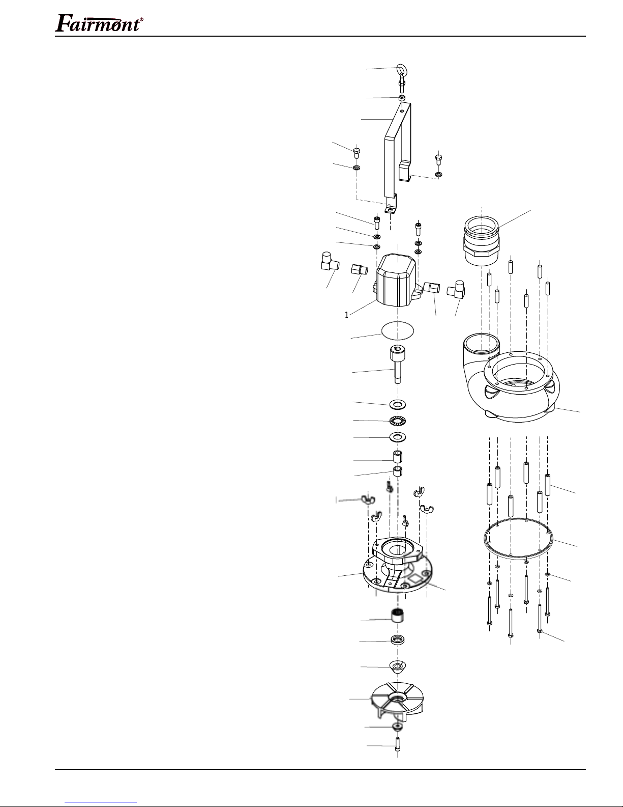
Exploded View and Parts List
5
9
3
6
32
6
5
2
8
0
5
3
3
3
9
33
9
31
30
8
0
8
918
H4635 / 49334 Submersible Trash Pump
H4635/49334 Submersible Trash Pump
UPC No.
Key 78-3310- Part No. Description Qty
1 50121 905 0121.7 Hydraulic motor ................................... 1
2 49496 49496 Housing (includes next two items)....... 1
49299 49299 Volute .................................................. 1
F023663 Stud, 3/8–16 x 1.50", stainless steel ... 6
3 49301 49301 Washer, cone ...................................... 1
4 46333 504 6333.0 Plate, cover ......................................... 1
5 46335 504 6335.7 Handle ................................................. 1
6 49315 49315 Impeller................................................ 1
7 50139 905 0139.0 Seal ..................................................... 1
8 49494 49494 Base .................................................... 1
9 55076 905 5076.5 Screw, cap, 1/4–20 x 3.25",
hex head, stainless steel ..................... 6
10 55077 905 5077.3 Screw, cap, 3/8–16 x .750",
hex head, stainless steel ..................... 2
11 55078 905 5078.1 Nut, wing, 3/8"–16, stainless steel....... 6
12 50141 905 0141.1 Adapter,
1-1/16 male SAE x 1/2" female NPT ... 1
13 F014243 Adapter,
7/8–14 male SAE x 1/2" female NPT .. 1
14 55081 905 5081.1 Coupling, cam locking, #30F male ...... 1
15 42094 F024580 O-ring, 3.25 x 3.375 x .062 – 70D ....... 1
17 F022405 Screw, cap, 3/8–16 x 1.00",
hex head, stainless steel ..................... 2
18 F023661 Washer, lock, .375", stainless steel..... 4
19 F024585 Screw, cap, 5/16–18 x 1.25",
socket head, stainless steel ................ 1
20 43079 L060311 Bushing, .500 x 2.4375", aluminum ..... 6
21 42813 L084018 Washer, lock, .250", stainless steel ..... 6
22 F014349 Washer, .375", flat, stainless steel ...... 2
23 43186 F011339 90° Elbow,
1/2 male NPT x 1/2" male NPT ........... 2
24 55515 905 5515.9 Eyebolt with nut, 3/8–16 x 3.50" .......... 1
25 41290 F007020 Nut, hex, 3/8"–16................................. 1
26 41547 F015482K1 Decal, Fairmont ................................... 1
27 46334 504 6334.9 Shaft, drive .......................................... 1
28 46336 504 6336.5 Guard, seal .......................................... 1
29 50142 905 0142.0 Washer, thrust ..................................... 2
30 50156 905 0156.0 Race, short bearing ............................. 1
31 50162 905 0162.4 Race, long bearing .............................. 1
32 50173 905 0173.0 Bearing, caged retained rollers ........... 1
33 50187 905 0187.0 Bearing, thrust, needle ........................ 1
2
1
1
2
2
1
2
1
2
2
2
2
Greenlee / A Textron Company 7 4455 Boeing Dr. • Rockford, IL 61109-2988 USA • 815-397-7070
2
1
Page 8
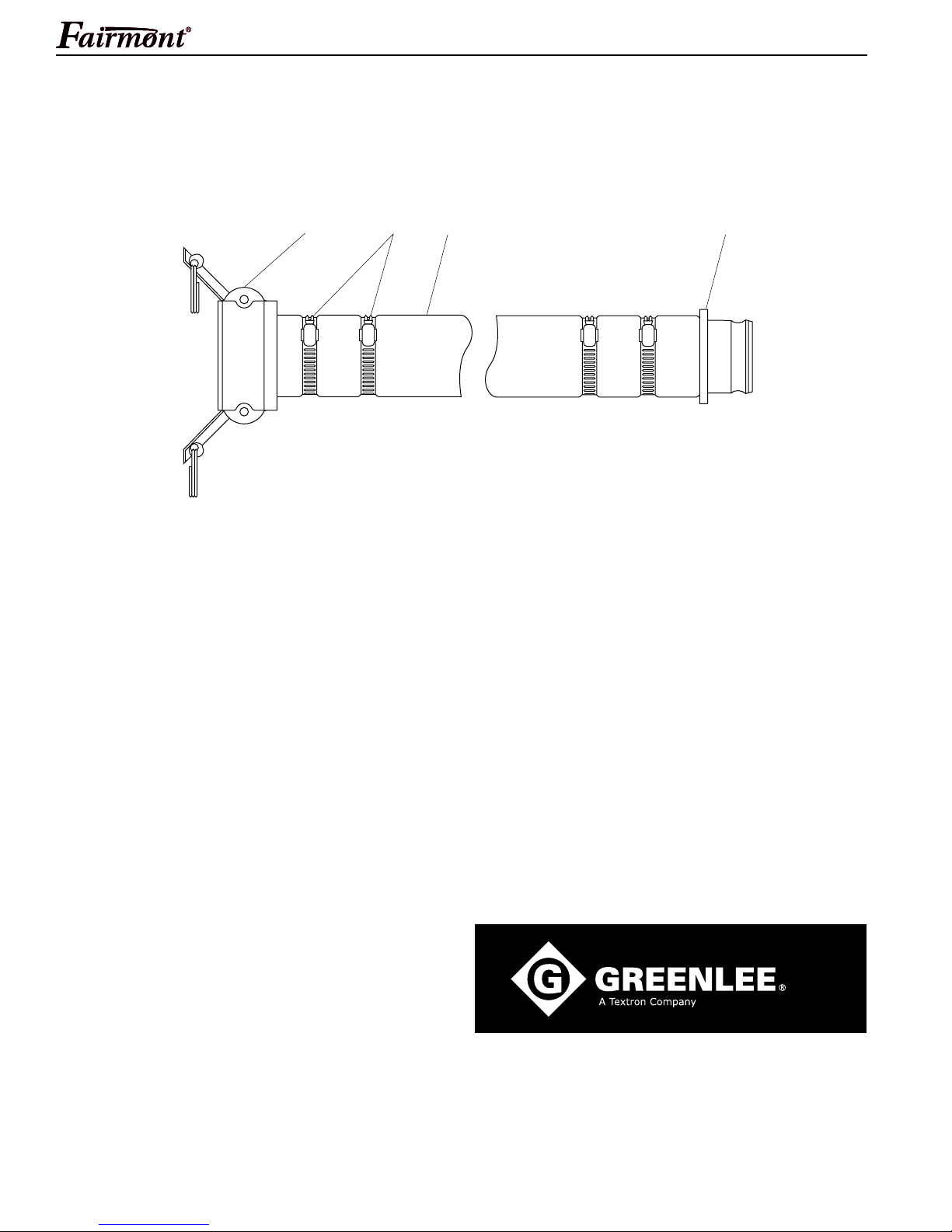
Accessories
Discharge Hose Assembly
H4635 / 49334 Submersible Trash Pump
3 421
Key Part No. Description Qty
49499 Hose assembly, heavy-duty discharge
1 905 5130.3 Coupling, cam lock............................................. 1
2 F10575 Clamp, hose, 3".................................................. 4
3 905 5129.0 Hose, discharge, 3" x 300"................................. 1
4 905 5210.5 Coupling, male ................................................... 1
905 5214.8 Hose assembly, contractor discharge
1 905 5130.3 Coupling, female ................................................ 1
2 F10575 Clamp, hose ....................................................... 4
4 905 5210.5 Coupling, male ................................................... 1
www.greenlee.com
Greenlee / A Textron Company 8 4455 Boeing Dr. • Rockford, IL 61109-2988 USA • 815-397-7070
USA (800) 435-0786 Fax: (800) 451-2632
(815) 397-7070 Fax: (815) 397-1865
Canada (800) 435-0786 Fax: (800) 524-2853
International +1 (815) 397-7070 Fax: +1 (815) 397-9247
4455 Boeing Drive, Rockford, IL 61109-2988 • USA • 815-397-7070
An ISO 9001 Company • Greenlee Textron is a subsidiary of Textron Inc.
 Loading...