

Page 1
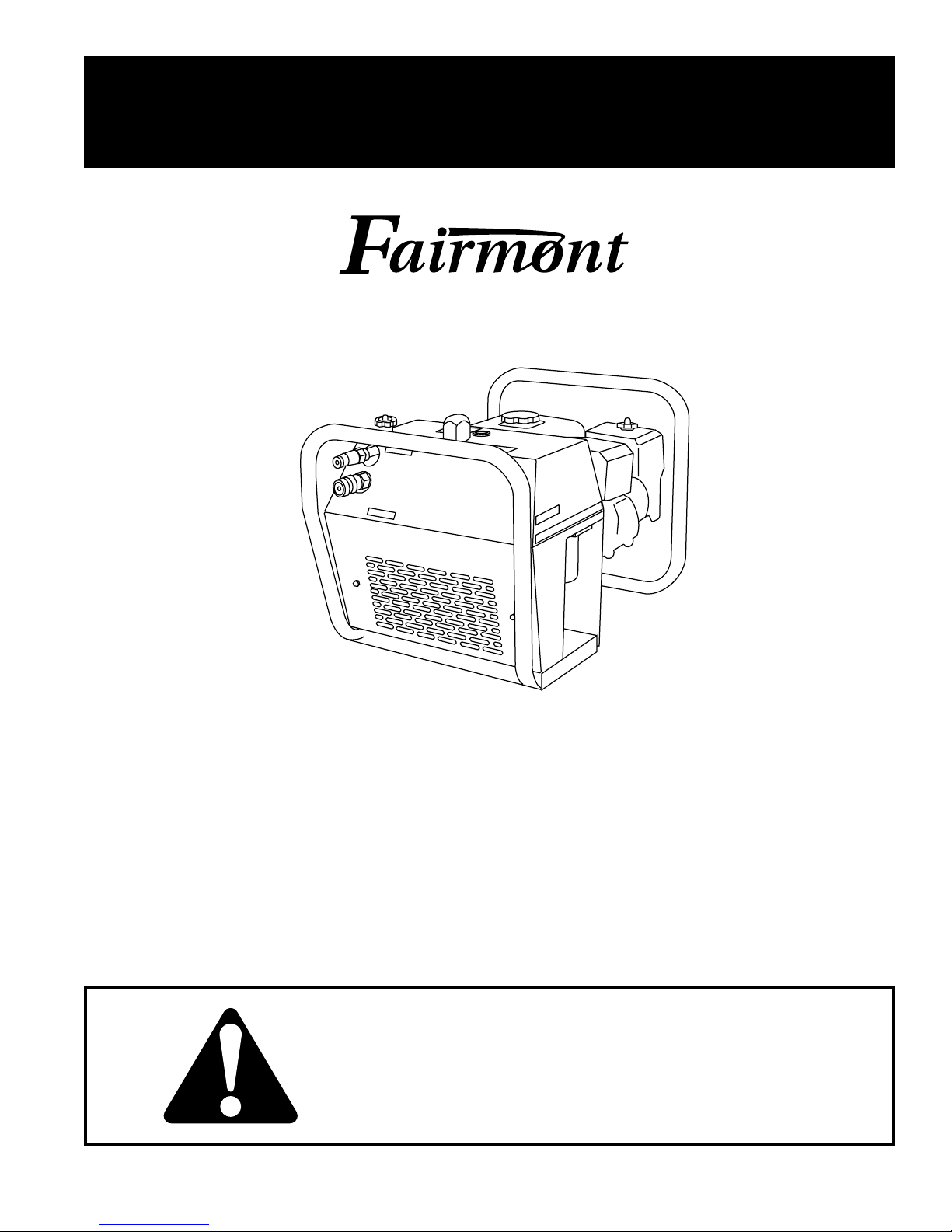
INSTRUCTION MANUAL
PORTABLE HYDRAULIC
999 3165.6 REV 1 © 1999 Greenlee Textron 12/99
F05 / 49616
POWER UNIT
Read and understand all of the instructions and
safety information in this manual before operating
or servicing this tool.
Page 2

F05 Portable Hydraulic Power Unit
Table of Contents
Description .....................................................................2
Safety.............................................................................2
Purpose..........................................................................2
Purchase Record ........................................................... 2
Important Safety Information .....................................3–4
Identification...................................................................5
Specifications.................................................................6
Hoses and Fittings .........................................................7
Hose Connections .........................................................7
Operation ...................................................................8–9
Maintenance ................................................................ 10
Troubleshooting ........................................................... 11
Exploded View .......................................................12–13
Parts List ................................................................14–15
Description
The Fairmont F05 Portable Hydraulic Power Unit is a
lightweight power source intended for use with open-
center hydraulic tools. The F05 provides a maximum
flow of 17 liters per minute (4.5 gallons per minute) and
a maximum pressure of 104.5 Bar (1500 psi).
Its compact size and light weight allow use at remote
worksites that might not be accessible by a larger power
unit or hydraulic truck. The ability to get close to the
work area allows the use of shorter hydraulic hoses,
increasing tool efficiency.
The simple design of the hydraulic circuit and reliable
Honda gasoline-powered engine ensure years of
trouble-free operation, when serviced according to the
maintenance schedule.
Safety
Safety is essential in the use and maintenance of
Fairmont tools and equipment. This instruction manual
and any markings on the tool provide information for
avoiding hazards and unsafe practices related to the
use of this tool. Observe all of the safety information
provided.
Purpose
This instruction manual is intended to familiarize all
personnel with the safe operation and maintenance
procedures for the Fairmont F05/49616 (Serial Code
GBP) Portable Hydraulic Power Unit.
Keep this manual available to all personnel.
Replacement manuals are available upon request at no
charge.
Purchase Record
When the tool is received, complete the following
record:
Model Number: _______________________________
Serial Number: _______________________________
Date of Purchase: _____________________________
Name of Fairmont Dealer: ______________________
A date code follows the serial number. The date code
consists of two alpha characters which identify year and
month of manufacture as follows:
Year Code Month Code
1999 R Jan A
2000 S Feb B
2001 T March C
2002 V April D
2003 W May E
2004 X June F
2005 Y July G
2006 Z Aug H
Sept J
Oct K
Nov L
Dec M
Greenlee Textron / Subsidiary of Textron Inc.
KEEP THIS MANUAL
2
4455 Boeing Dr., Rockford, IL 61109-2988 815/397-7070
Page 3
F05 P ortable Hydraulic Power Unit
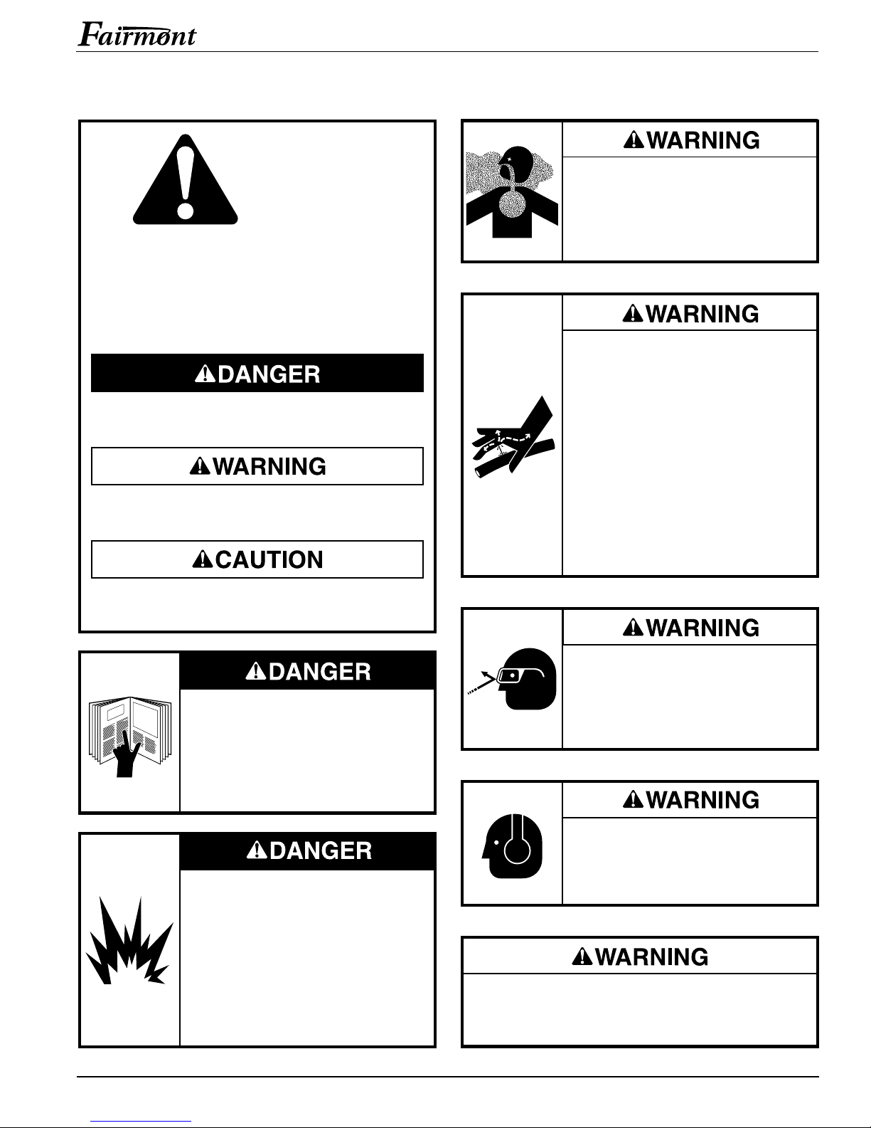
IMPORTANT SAFETY INFORMATION
SAFETY
ALERT
SYMBOL
This symbol is used to call your attention to hazards
or unsafe practices which could result in an injury
or property damage. The signal word, defined below,
indicates the severity of the hazard. The message after
the signal word provides information for preventing or
avoiding the hazard.
Immediate hazards which, if not avoided, WILL result
in severe injury or death.
Hazards which, if not avoided, COULD result in severe
injury or death.
Do not run power unit engine in a
confined area.
Engine exhaust fumes are toxic.
If inhaled, exhaust fumes can cause
injury or death.
Skin injection hazard:
Oil under pressure easily punctures
skin causing serious injury, gangrene
or death. If you are injured by
escaping oil, seek medical attention
immediately.
• Do not use fingers or hands to
check for leaks.
• Do not hold hose or couplers while
the hydraulic system is pressurized.
• Depressurize the hydraulic system
before servicing or disconnecting
hoses.
Hazards or unsafe practices which, if not avoided,
MAY result in injury or property damage.
Read and understand all of the
instructions and safety information
in this manual before operating or
servicing this tool.
Failure to observe this warning will
result in severe injury or death.
Fuel is flammable and explosive.
• Stop engine before filling fuel tank.
• Do not fill fuel tank when engine
is hot.
• Do not fill fuel tank near an open
flame, sparks, or when smoking.
Failure to observe this warning will
result in severe injury or death.
Wear eye protection when operating
or servicing this tool.
Failure to wear eye protection can
result in serious eye injury from
flying debris or hydraulic oil.
Wear hearing protection when using
this tool.
Failure to observe this warning can
result in serious injury.
Do not disconnect tool, hoses or fittings while the
power source is running or if the hydraulic fluid is
hot. Hot hydraulic fluid can cause serious burns.
Greenlee Textron / Subsidiary of Textron Inc.
3
4455 Boeing Dr., Rockford, IL 61109-2988 815/397-7070
Page 4
F05 Portable Hydraulic Power Unit
IMPORTANT SAFETY INFORMATION
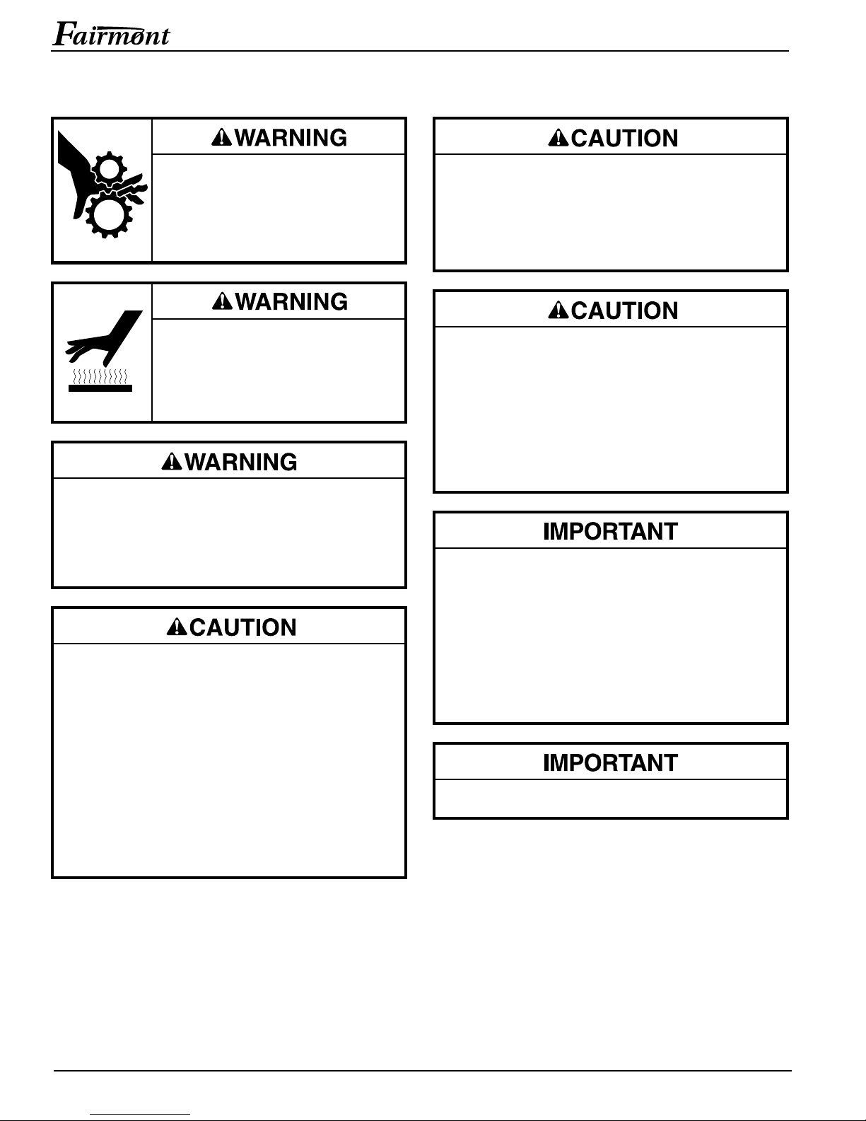
• Do not operate power unit without
safety guards in place.
• Keep all parts of the body and
loose clothing away from the
engine fan.
Engine, exhaust system, and other
components will be hot during and
after operation. Use care when
working around the power unit. Hot
surfaces can cause serious burns.
Do not let power unit engine run unattended.
Monitor the engine so that it can be shut down
immediately in case of a malfunction.
Failure to observe this warning can result in
severe injury or death.
• Inspect the hydraulic hoses and couplings every
operating day. Repair or replace if leakage, cracking, wear, or damage is evident. Damaged hoses
or couplings can fail, resulting in injury or property
damage.
• Use this power source for manufacturer’s intended
purpose only. Use other than that which is
described in this manual can result in injury or
property damage.
• Make sure all bystanders are clear of the work area
when handling, starting, and operating the power
source. Nearby personnel can be injured by flying
parts in the event of a tool malfunction.
Use appropriate lifting equipment. Make sure all
components used to lift this power unit are rated for
90 kg (200 lbs) and are securely attached to the
frame of the power unit. Inadequate components
may fail and cause the power unit to fall, resulting
in injury or property damage.
Hydraulic oil can cause skin irritation.
• Handle the tool and hoses with care to prevent
skin contact with hydraulic oil.
• In case of accidental skin contact with hydraulic
oil, wash the affected area immediately to
remove the oil.
Failure to observe these precautions can result in
injury.
Procedure for connecting or disconnecting hydraulic
hoses, fittings or components:
1. Rotate the flow control knob to the OFF
position.
2. Switch the engine OFF.
3. Follow the sequence under Hose Connections
to prevent pressure buildup. In case some
pressure has built up, loosen hoses, fittings or
components slowly.
Emergency stop procedure: Switch the engine OFF.
Note: Keep decals clean and legible. Replace decals
when necessary.
Greenlee Textron / Subsidiary of Textron Inc.
4
4455 Boeing Dr., Rockford, IL 61109-2988 815/397-7070
Page 5
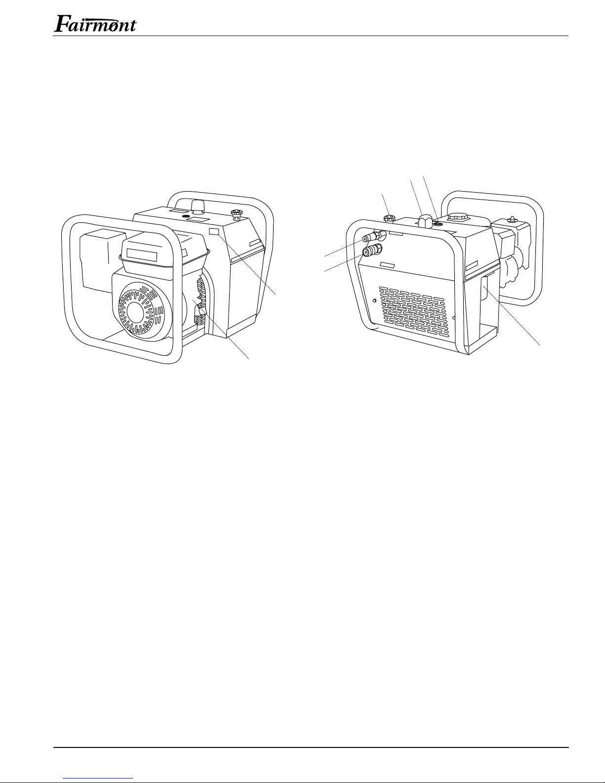
Identification
1
2
8
7
6
5
4
3
F05 P ortable Hydraulic Power Unit
Parts of the F05 Portable Hydraulic Power Unit
1. Gasoline-Powered Engine 5. Flow Control Knob
2. Serial Number 6. Hydraulic Reservoir Cap
3. Hydraulic Tank Coupler 7. Hydraulic Oil Sight Gauge
4. Hydraulic Pressure Coupler 8. Hydraulic Fluid Filter
Greenlee Textron / Subsidiary of Textron Inc.
5
4455 Boeing Dr., Rockford, IL 61109-2988 815/397-7070
Page 6

Specifications
F05 Portable Hydraulic Power Unit
Overall Physical Dimensions
Mass/Weight (Dry) ..................................38.1 kg (84 lbs)
Length ..................................................... 596 mm (23.5")
Width....................................................... 431 mm (17.0")
Height......................................................419 mm (16.5")
Hydraulic Characteristics
Type of Hydraulic System...........................Open-Center
Pressure Port ........... 3/8" Male HTMA Quick Disconnect
Tank Port ............. 3/8" Female HTMA Quick Disconnect
Output (Maximum)
Flow............................. 17 to 20 l/min (4.5 to 5.3 gpm)
Pressure ......................................104.5 Bar (1500 psi)
Hydraulic Fluid Capacity ............. 6.6 liters (1.74 gallons)
Filtration .......................................... 10 Micron (Nominal)
Recommended Hydraulic Fluids
Use any non-detergent, petroleum-based hydraulic fluid
which meets these specifications:
Metric
Viscosity (Measured in Centistokes)
38° C..................................................... 30 to 48 cSt
99° C.............................................. 4.2 cSt Minimum
Flash Point .............. Equal to or Greater Than 170° C
Pour Point......................Equal to or Less Than -34° C
SAE
Viscosity (Measured in Saybolt Universal Seconds)
100° F ............................................. 140 to 225 SUS
210° F ...........................................40 SUS Minimum
Flash Point ............... Equal to or Greater Than 340° F
Pour Point...................... Equal to or Less Than -30° F
Some hydraulic fluids which meet these criteria include,
but are not limited to, the following:
Manufacturer Catalog Number
American Oil Co. (Amoco) Rykon 32
Rykon 46
Conoco Super Hydraulic Oil 5W-20
Phillips Petroleum Co. Magnus A 150
Magnus A 215
Sun Oil Co. (Sunoco) Sun Hydraulic Oil 2105
Texaco Rando B
Rando HDAZ
Rando HD32
Rando HD46
Union Oil Co. Unax AW 150
Unax AW 215
Engine Characteristics
See engine owner’s manual.
Greenlee Textron / Subsidiary of Textron Inc.
6
4455 Boeing Dr., Rockford, IL 61109-2988 815/397-7070
Page 7
F05 P ortable Hydraulic Power Unit
Hoses and Fittings
Installation and Maintenance
See publication 999 3032.3, SAE J1273
(Hose and Hose Assemblies).
Replacement
Refer to a Fairmont catalog or publication 999 1032.2,
Low Pressure Quick Couplers, Adapters and Hoses.
Hose Connections
Power Source Port Identification
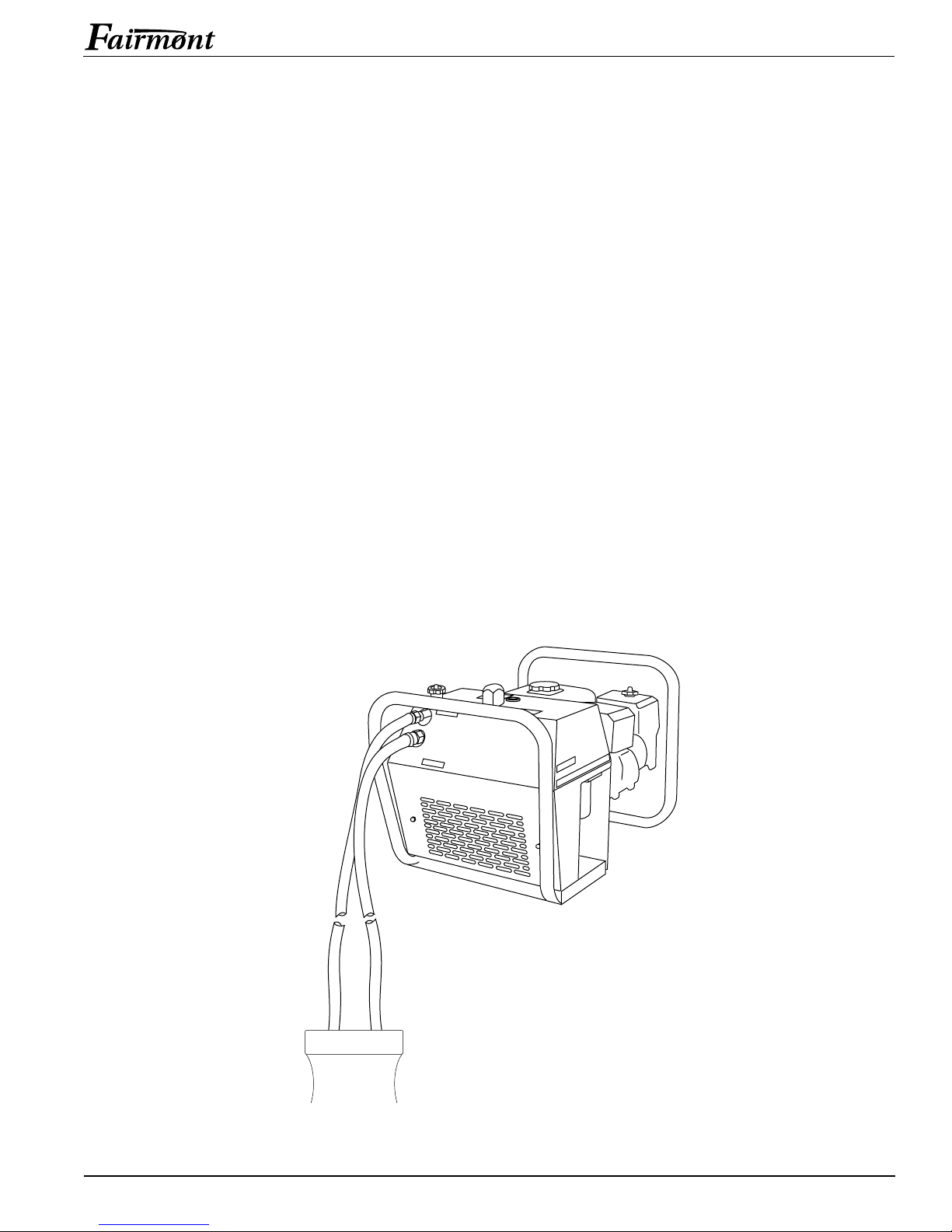
The pressure port on the power unit is the upper port
(labeled PRESSURE). The tank port is the lower port
(labeled RETURN).
Connecting Hoses
1. Rotate the flow control knob completely counterclockwise (OFF).
2. Switch the engine OFF.
3. Connect the tank hose to the tank port on the power
source, and then to the tank port on the tool.
4. Connect the pressure hose to the pressure port on
the tool, and then to the pressure port on the power
source.
Disconnecting Hoses
1. Rotate the flow control knob completely counterclockwise (OFF).
2. Switch the engine OFF.
3. Disconnect the pressure hose from the power
source, and then from the tool.
4. Disconnect the tank hose from the tool, and then
from the power source.
Greenlee Textron / Subsidiary of Textron Inc.
TOOL
TankPressure
7
4455 Boeing Dr., Rockford, IL 61109-2988 815/397-7070
Page 8
Operation
F05 Portable Hydraulic Power Unit
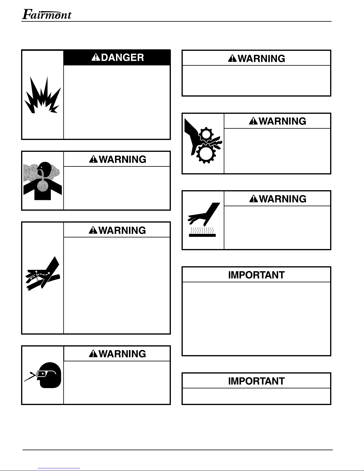
Fuel is flammable and explosive.
• Stop engine before filling fuel tank.
• Do not fill fuel tank when engine
is hot.
• Do not fill fuel tank near an open
flame, sparks, or when smoking.
Failure to observe this warning will
result in severe injury or death.
Do not run power unit engine in a
confined area.
Engine exhaust fumes are toxic.
If inhaled, exhaust fumes can cause
injury or death.
Skin injection hazard:
Oil under pressure easily punctures
skin causing serious injury, gangrene
or death. If you are injured by
escaping oil, seek medical attention
immediately.
• Do not use fingers or hands to
check for leaks.
• Do not hold hose or couplers while
the hydraulic system is pressurized.
• Depressurize the hydraulic system
before servicing.
Do not disconnect tool, hoses or fittings while the
power source is running or if the hydraulic fluid is
hot. Hot hydraulic fluid can cause serious burns.
• Do not operate power unit without
safety guards in place.
• Keep all parts of the body and
loose clothing away from the
engine fan.
Engine, exhaust system, and other
components will be hot during and
after operation. Use care when
working around the power unit. Hot
surfaces can cause serious burns.
Procedure for connecting or disconnecting hydraulic
hoses, fittings or components:
1. Rotate the flow control knob to the OFF
position.
2. Switch the engine OFF.
3. Follow the sequence under Hose Connections
to prevent pressure buildup. In case some
pressure has built up, loosen hoses, fittings or
components slowly.
Wear eye protection when operating
or servicing this tool.
Failure to wear eye protection can
result in serious eye injury from
flying debris or hydraulic oil.
Greenlee Textron / Subsidiary of Textron Inc.
Emergency stop procedure: Switch the engine OFF.
8
4455 Boeing Dr., Rockford, IL 61109-2988 815/397-7070
Page 9
F05 P ortable Hydraulic Power Unit
Operation (cont’d)
Transportation
Use appropriate lifting equipment. Make sure all
components used to lift this power unit are rated for
90 kg (200 lbs) and are securely attached to the
frame of the power unit. Inadequate components may
fail and cause the power unit to fall, resulting in injury
or property damage.
1. Stop the power unit. See Stopping the Power Unit
under Operation.
2. Allow the power unit to cool.
3. Attach lifting equipment securely to the frame of the
unit.
Pre-Start
1. Position the power source on firm level ground.
2. Refer to the engine owner’s manual to:
• Check the engine oil level. Add oil if necessary.
• Check the fuel level. Add fuel if necessary.
• Verify that any other maintenance has been
performed according to the schedule.
3. Connect the hoses and tool to the power unit. See
Hose Connections in this manual.
Stopping the Power Unit
Set the flow control knob to the OFF position before
shutting the engine off. Shutting the engine off with
the control knob in the ON position will allow gasoline
into the exhaust system.
Failure to observe this precaution can result in
property damage.
1. Rotate the flow control knob completely counterclockwise (OFF).
2. Move the engine control lever to the slowest setting.
Allow the engine to idle for a few moments.
3. Switch the engine OFF.
Starting the Power Unit
1. Rotate the flow control knob completely counterclockwise (OFF).
2. Refer to the engine owner’s manual to start the
engine. Allow the engine to idle for a few minutes to
warm the hydraulic fluid.
3. Move the control lever to the proper setting.
4. Rotate the flow control knob clockwise (ON) to
supply hydraulic power to the tool.
5. Refer to the tool owner’s manual for tool operating
instructions.
Tips for cold weather operation:
• See the engine manufacturer’s cold start instructions.
• Allow the engine a longer idle time to warm the
hydraulic fluid (with the hydraulic control knob in the
OFF position). Warm hydraulic fluid puts less internal
pressure on the hoses than cold hydraulic fluid.
Greenlee Textron / Subsidiary of Textron Inc.
9
4455 Boeing Dr., Rockford, IL 61109-2988 815/397-7070
Page 10
Maintenance
F05 Portable Hydraulic Power Unit
MAINTENANCE SCHEDULE
Use this schedule to maximize the power unit’s service
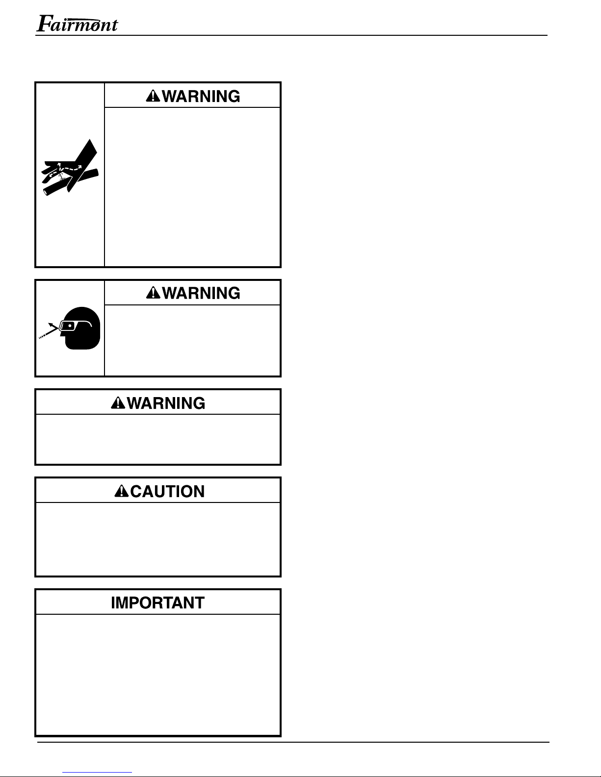
Skin injection hazard:
Oil under pressure easily punctures
skin causing serious injury, gangrene
or death. If you are injured by
escaping oil, seek medical attention
immediately.
• Do not use fingers or hands to
check for leaks.
• Do not hold hose or couplers while
the hydraulic system is pressurized.
• Depressurize the hydraulic system
before servicing.
Wear eye protection when operating
or servicing this tool.
Failure to wear eye protection can
result in serious eye injury from
flying debris or hydraulic oil.
life. See the tool owner’s manual and the engine
owner’s manual for the maintenance of those items.
Note: Keep decals clean and legible. Replace decals
when necessary.
Every 5 Hours
1. Check the engine crankcase oil level. See the
engine owner’s manual.
2. Check the hydraulic reservoir oil level. Add oil until
the sight tube indicates FULL. See Recommended
Hydraulic Fluids under Specifications.
Every 10 Hours
1. Wipe all surfaces clean.
2. Inspect the hydraulic hoses and fittings for signs
of leaks, cracks, wear or damage. Replace if
necessary.
Every Month
Perform a thorough inspection of the hydraulic hoses
and fittings as described in publication 999 3032.3,
SAE J1273 (Hose and Hose Assemblies).
Do not disconnect tool, hoses or fittings while the
power source is running or if the hydraulic fluid is
hot. Hot hydraulic fluid can cause serious burns.
Do not overfill the engine crankcase or the hydraulic
reservoir. Overfilling either of these will cause severe
internal damage and void the warranty.
Failure to observe this precaution will result in
damage to the power unit.
Procedure for connecting or disconnecting hydraulic
hoses, fittings or components:
1. Rotate the flow control knob to the OFF
position.
2. Switch the engine OFF.
3. Follow the sequence under Hose Connections
to prevent pressure buildup. In case some
pressure has built up, loosen hoses, fittings or
components slowly.
Every 100 Hours or Annually
Note: Perform this procedure more often if the power
source is used in cold, moist or dusty conditions.
1. Drain the hydraulic fluid reservoir.
2. Clean and flush the reservoir. Change the hydraulic
filter. Fill the reservoir with new, clean hydraulic
fluid. Add oil until the sight tube indicates FULL.
3. Operate the power unit to circulate the oil through
the hydraulic system. Stop the power unit and check
the hydraulic fluid level. Add oil until the sight tube
indicates FULL.
4. Dispose of used oil and filter in accordance with
federal, state and local laws.
Annual Inspection
If required by your organization’s regulations, have the
tool inspected by an authorized Fairmont service center.
Greenlee Textron / Subsidiary of Textron Inc.
10
4455 Boeing Dr., Rockford, IL 61109-2988 815/397-7070
Page 11
Troubleshooting
F05 Portable Hydraulic Power Unit
Before troubleshooting, determine whether the problem
is in the tool, the hoses, or the power source. Substitute
a tool, hoses, or power source known to be in good
working order to eliminate the item that is not operating.
PROBABLE CAUSEPROBLEM PROBABLE REMEDY
Engine trouble. See engine owner’s manual.
Tool doesn’t operate. Improper power source. Verify that the power source meets the
Hydraulic fluid level low. Check the fluid level. Check system for leaks.
Incorrect hydraulic fluid viscosity. Use hydraulic fluid with the correct viscosity.
Power source output is low. Measure the flow, pressure and back pressure of
Tool operates slowly or Hydraulic fluid cold. Allow fluid to warm to the operating temperature.
erratically. Actuate the tool intermittently to reduce the
If the problem is in the tool, see the troubleshooting
section of the tool instruction manual. If the problem is
in the power source, see the troubleshooting table
below.
tool’s specifications.
See Recommended Hydraulic Fluids.
the power source. If output is low, send the power
source to an authorized Fairmont service
center for repair.
warming time.
Hydraulic fluid level low. Check the fluid level. Check system for leaks.
Incorrect hydraulic fluid viscosity. Use hydraulic fluid with the correct viscosity.
See Recommended Hydraulic Fluids.
Power source output is low. Measure the flow, pressure and back pressure of
the power source. If output is low, send the power
source to an authorized Fairmont service
center for repair.
Tool feels hot. Hydraulic fluid level low. Check the fluid level. Check system for leaks.
Incorrect hydraulic fluid viscosity. Use hydraulic fluid with the correct viscosity.
See Recommended Hydraulic Fluids.
Hydraulic fluid dirty. Replace the hydraulic oil and filter.
Power source output is low. Measure the flow, pressure and back pressure of
the power source. If output is low, send the power
source to an authorized Fairmont service
center for repair.
Greenlee Textron / Subsidiary of Textron Inc.
11
4455 Boeing Dr., Rockford, IL 61109-2988 815/397-7070
Page 12
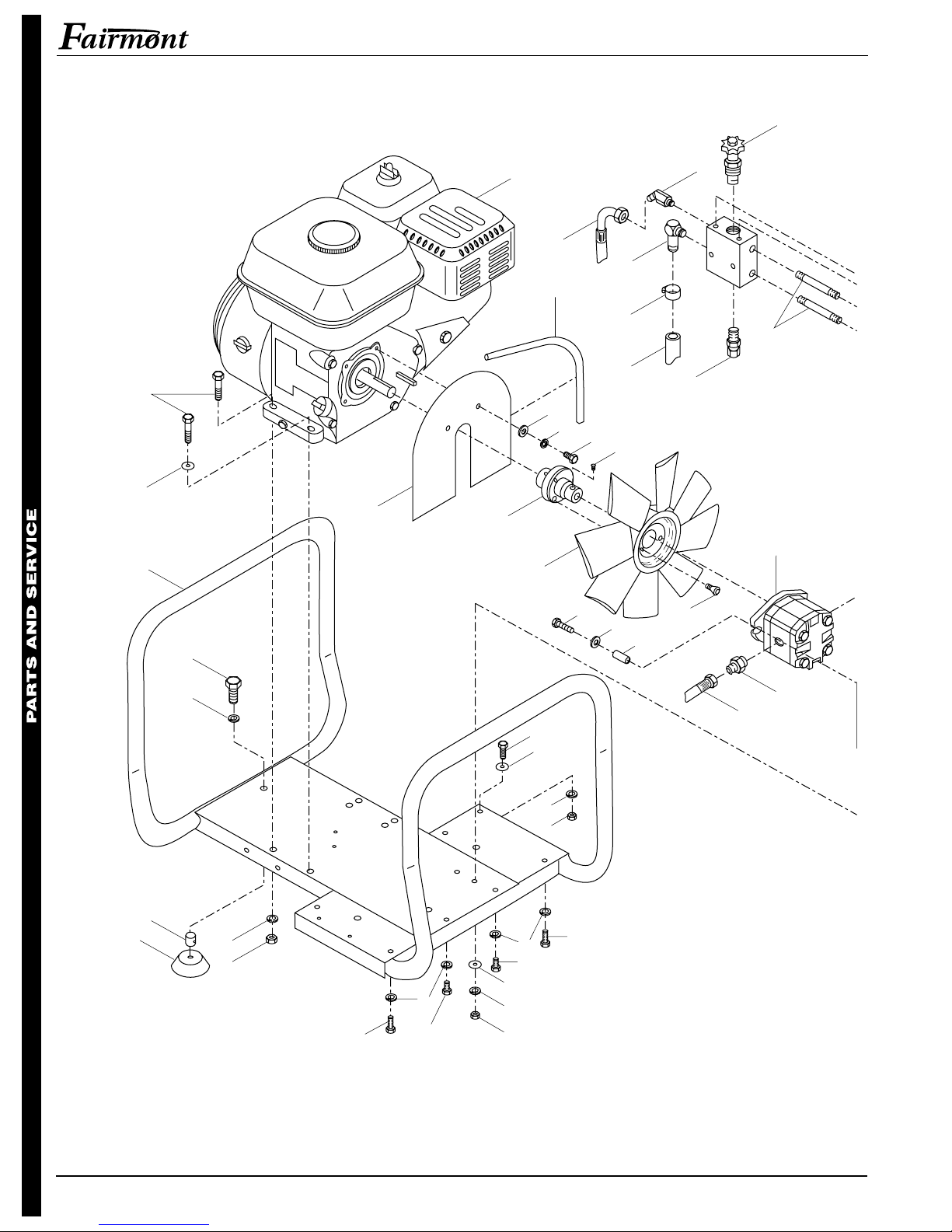
Exploded View
F05 Portable Hydraulic Power Unit
31
16
49
30
19
44
46
43
47
57
51
16
15
33
20
22
61
10
21
24
1
13
17
14
45
64
37
50
6
3
10
7
4
15
7
9
7
3
18
18
10
7
4
3
42
57
Greenlee Textron / Subsidiary of Textron Inc.
12
4455 Boeing Dr., Rockford, IL 61109-2988 815/397-7070
Page 13
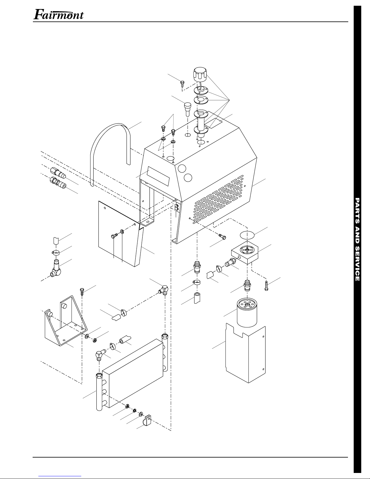
F05 Portable Hydraulic Power Unit
35
58
22
32
40
41
38
29
18
51
7
66
2
38
62
3
7
23
39
22
59
25
22
28
65
52
53
34
39
36
22
61
10
5
48
56
Greenlee Textron / Subsidiary of Textron Inc.
22
23
4
7
10
59
58
26
63
8
13
4455 Boeing Dr., Rockford, IL 61109-2988 815/397-7070
Page 14
Parts List
F05 Portable Hydraulic Power Unit
KEY UPC NO. PART NO. DESCRIPTION QTY.
1 49625 504 9625.5 Fitting, 3/8" x 2.5 Nipple ....................................2
2 49626 504 9626.3 Nut, Jam ..........................................................11
3 49627 504 9627.1 Bolt, 1/4" NC x 3/4 ...........................................14
4 49628 504 9628.0 Nut, 1/4".............................................................7
5 49629 504 9629.8 Nut, 1/4" Nylon Insert ........................................2
6 49630 504 9630.1 Washer, 3/8" Lock .............................................3
7 49631 504 9631.0 Washer, 1/4" Lock ...........................................18
8 49632 504 9632.8 Clamp ................................................................2
9 49633 504 9633.6 Nut, 5/16"...........................................................4
10 49634 504 9634.4 Washer, 1/4" Flat, Plated.................................11
13 49635 504 9635.2 Valve, Relief ......................................................1
14 49636 504 9636.0 Pump .................................................................1
15 49637 504 9637.9 Washer, 5/16" Lock, Plated ...............................8
16 49638 504 9638.7 Washer, 5/16" Flat.............................................6
17 49639 504 9639.5 Screw ................................................................2
18 49640 504 9640.9 Bolt, 1/4" x 1/2 ...................................................4
19 49641 504 9641.7 Bolt, 3/8" x 1 ......................................................3
20 49642 504 9642.5 Bolt, 5/16" x 1 ....................................................4
21 49643 504 9643.3 Fitting.................................................................1
22 49644 504 9644.1 Clamp, Hose......................................................6
23 49645 504 9645.0 Fitting.................................................................2
24 49646 504 9646.8 Fitting.................................................................1
25 49647 504 9647.6 Fitting.................................................................1
26 49648 504 9648.4 Filter ..................................................................1
27 49649 504 9649.2 Manifold .............................................................1
28 49650 504 9650.6 Cap, Hydraulic Fill .............................................1
29 49651 504 9651.4 Gauge, Sight .....................................................1
30 49652 504 9652.2 Bolt, 5/16" x 1-1/4 ..............................................4
31 49653 504 9653.0 Valve .................................................................1
32 49654 504 9654.9 Fitting.................................................................1
Greenlee Textron / Subsidiary of Textron Inc.
14
4455 Boeing Dr., Rockford, IL 61109-2988 815/397-7070
Page 15
F05 Portable Hydraulic Power Unit
Parts List (cont’d)
KEY UPC NO. PART NO. DESCRIPTION QTY.
33 49655 504 9655.7 Bolt, 1/4" x 1-1/2 ................................................2
34 49656 504 9656.5 Filter, Manifold, Hydraulic ..................................1
35 49657 504 9657.3 Screw ................................................................3
36 49658 504 9658.1 Bolt, 1/4" x 1 ......................................................4
37 49659 504 9659.0 Foot ...................................................................3
38 49660 504 9660.3 Bolt, 1/4" x 1 ......................................................6
39 49661 504 9661.1 Fitting.................................................................1
40 49662 504 9662.0 Coupler, Hydraulic .............................................1
41 49663 504 9663.8 Coupler, Hydraulic .............................................1
42 49664 504 9664.6 Fitting.................................................................1
43 49665 504 9665.4 Engine, Honda 5.5 H.P......................................1
44 49666 504 9666.2 Fan, Guard at Engine ........................................1
45 49667 504 9667.0 Bolt, 1/4" x 1/2 Socket Head..............................3
46 49668 504 9668.9 Pump, Coupler to Engine ..................................1
47 49669 504 9669.7 Fan ....................................................................1
48 49670 504 9670.0 Pump, Mount .....................................................1
49 49671 504 9671.9 Frame ................................................................1
50 49672 504 9672.7 Spacer, Foot ......................................................3
51 49673 504 9673.5 Trim, 1/8" ...........................................................2
52 49674 504 9674.3 Tank, Hydraulic .................................................1
53 49675 504 9675.1 O-ring ................................................................1
56 49676 504 9676.0 Cooler ................................................................1
57 49677 504 9677.8 Hose, Pressure..................................................1
58 49678 504 9678.6 Hose, 1/2" x 4 ....................................................1
59 49679 504 9679.4 Hose, 1/2" x 12 ..................................................1
61 49680 504 9680.8 Hose, 1/2" x 19 ..................................................1
62 49681 504 9681.6 Panel, Side ........................................................1
63 49682 504 9682.4 Panel, Filler .......................................................1
64 49683 504 9683.2 Dampener, Vibration .........................................2
65 49749 504 9749.9 Decal, Top Panel ...............................................1
66 49746 504 9746.4 Decal, Side Panel ..............................................2
Greenlee Textron / Subsidiary of Textron Inc.
15
4455 Boeing Dr., Rockford, IL 61109-2988 815/397-7070
Page 16

Greenlee Textron / Subsidiary of Textron Inc.
4455 Boeing Drive, Rockford, IL 61109-2988 USA
Customer Service (International): 815/397-7070 • Fax: 815/397-9247
Customer Service (North America): 800/435-0786 • Fax: 800/451-2632, 815/397-1865
Canada Fax: 800/524-2853
Printed in the U.S.A.
 Loading...