

Page 1
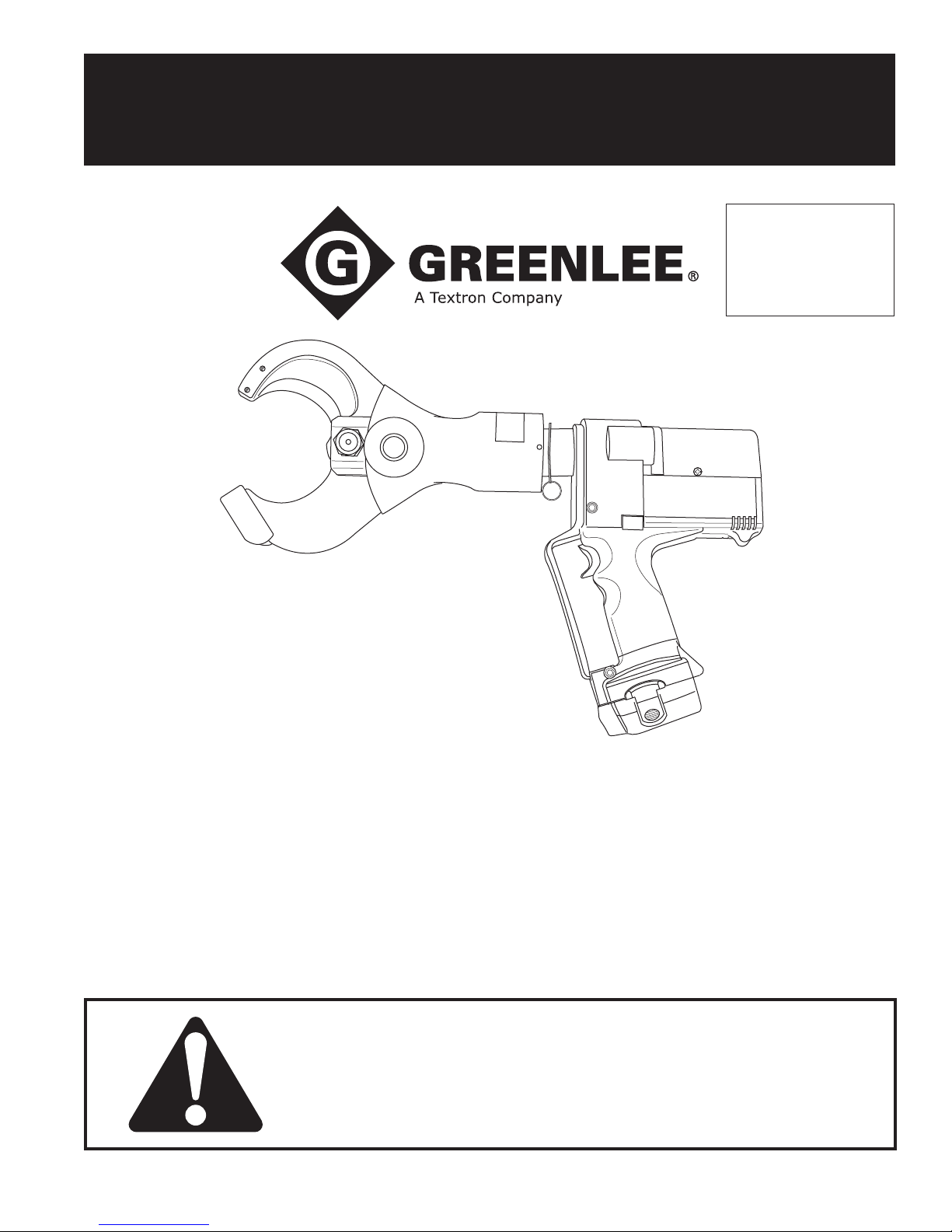
INSTRUCTION MANUAL
Serialnummer
GATOR® Plus
Battery-powered
Cable Cutter
Read and understand all of the instructions and
safety information in this manual before operating
or servicing this tool.
52020651 REV 3 © 2008 Greenlee Textron Inc. 3/08
ESC85
Page 2

ESC85 Battery-powered Cable Cutter
Table of Contents
Description .................................................................... 2
Safety ............................................................................ 2
Purpose of this Manual ................................................. 2
Important Safety Information .....................................3–4
Identication .................................................................. 5
Specications ................................................................ 5
Operation ....................................................................... 6
Maintenance .................................................................. 7
Troubleshooting ............................................................. 8
Disassembly .................................................................. 9
Assembly ..................................................................... 10
Illustrations .............................................................11–13
Parts List ................................................................14–16
Description
The ESC85 Battery-powered Cable Cutter is a handheld tool intended to cut copper and aluminum cable
up to 85 mm (3-1/4") in diameter. This tool is intended
to cut most low- and medium-voltage stranded copper
and aluminum cable found on most job sites.
Safety
Safety is essential in the use and maintenance of
Greenlee tools and equipment. This manual and any
markings on the tool provide information for avoiding
hazards and unsafe practices related to the use of this
tool. Observe all of the safety information provided.
Purpose of this Manual
This manual is intended to familiarize all personnel with
the safe operation and maintenance procedures for the
following Greenlee tool:
ESC85 Battery-powered Cable Cutter
Keep this manual available to all personnel.
Replacement manuals are available upon request at
no charge.
Greenlee / A Textron Company 4455 Boeing Dr. • Rockford, IL 61109-2988 USA • 815-397-7070
All specications are nominal and may change as design
improvements occur. Greenlee Textron Inc. shall not be liable for
damages resulting from misapplication or misuse of its products.
GATOR is a trademark of Greenlee Textron Inc.
AVIA is a registered trademark of Avia International.
Mobil is a registered trademark of Mobil Oil Corporation.
NUTO is a registered trademark of Exxon Corporation.
Tellus is a registered trademark of Shell Oil Company.
Molykote is a registered trademark of Dow Corning Corporation.
KEEP THIS MANUAL
2
Page 3
IMPORTANT SAFETY INFORMATION
SAFETY
ALERT
SYMBOL
This symbol is used to call your attention to hazards
or unsafe practices which could result in an injury or
property damage. The signal word, dened below,
indicates the severity of the hazard. The message
after the signal word provides information for preventing or avoiding the hazard.
Immediate hazards which, if not avoided, WILL result
in severe injury or death.
Hazards which, if not avoided, COULD result in
severe injury or death.
ESC85 Battery-powered Cable Cutter
Electric shock hazard: The owner of this cutter
•
must be certain that all users of this tool are trained
in the applicable safety codes and standards
as well as in the safe use of this tool and its
accessories.
Do not cut cable under tension.
•
Use the tool for its intended purpose, which is
•
cutting cable.
Failure to observe these warnings could result in
severe injury or death.
Wear eye protection when operating
or servicing this tool.
Failure to wear eye protection could
result in serious eye injury from ying
debris or hydraulic oil.
Hazards or unsafe practices which, if not avoided,
MAY result in injury or property damage.
Read and understand all of the
instructions and safety information
in this manual before operating or
servicing this tool.
Failure to observe this warning could
result in severe injury or death.
Electric shock hazard:
This tool is not insulated. When using
this unit near energized electrical
lines, use proper personal protective
equipment.
Failure to observe this warning could
result in severe injury or death.
Skin injection hazard:
Do not use hands to check for oil
leaks. High pressure oil easily punctures skin causing serious injury,
gangrene, or death. If injured, seek
medical help immediately to remove
oil.
Do not use solvents or ammable
liquids to clean the tool body.
Solvents or ammable liquids could
ignite and cause serious injury or
property damage.
Greenlee / A Textron Company 4455 Boeing Dr. • Rockford, IL 61109-2988 USA • 815-397-7070
3
Page 4
ESC85 Battery-powered Cable Cutter
IMPORTANT SAFETY INFORMATION
Keep hands away from closing
blades.
Failure to observe this warning could
result in severe injury or death.
Do not dispose of batteries in a re. They will vent
fumes and may explode.
Failure to observe this warning could result in severe
injury from harmful fumes or burns from ying debris.
Do not cut steel or ACSR. Cut only copper and
•
aluminum cable.
This tool is not designed for continuous use. After
•
30 to 40 cutting cycles, allow the tool to cool for
15 minutes.
Do not place the tool in a vise. The tool is designed
•
for hand-held operation.
Protect the tool from rain and moisture.
•
damage the tool and battery.
Store the tool in the case when not in use.
•
Failure to observe these precautions may result in
injury or property damage.
Water will
Do not allow anything to contact the battery
terminals.
Do not immerse the batteries in liquid. Liquid may
•
create a short circuit and damage the battery.
If batteries are immersed, contact your service
center for proper handling.
Do not place the battery into a pocket, tool pouch,
•
or tool box with conductive objects. Conductive
objects may create a short circuit and damage the
battery.
Do not place a battery on moist ground or grass.
•
Moisture may create a short circuit and damage
the battery.
Failure to observe these precautions may result in
injury or property damage.
Do not store the battery at more than 60 °C
•
(140 °F). Damage to the battery can result.
Do not use another manufacturer’s charger. Other
•
manufacturers’ chargers may overcharge and
damage the battery.
Do not attempt to open the battery. It contains no
•
user-serviceable parts.
Failure to observe these precautions may result in
injury or property damage.
Greenlee / A Textron Company 4455 Boeing Dr. • Rockford, IL 61109-2988 USA • 815-397-7070
Use all appropriate and applicable personal safety
equipment as required such as safety shoes, hard
hat, and safety glasses. Follow all safety rules and
regulations for the job.
Failure to comply may result in personal injury or
property damage.
Note: Keep all decals clean and legible, and replace
when necessary.
4
Page 5
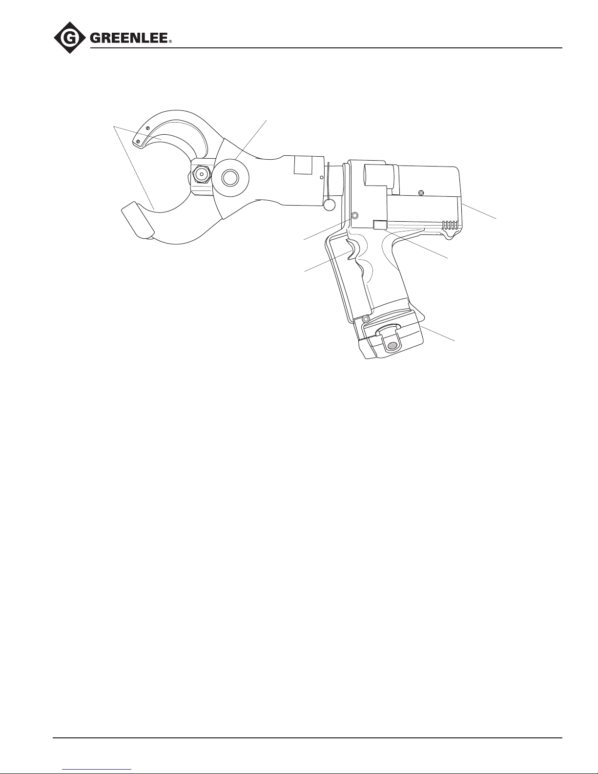
Identification
5
1
2
3
4
6
7
ESC85 Battery-powered Cable Cutter
ESC85 Cable Cutter
1. Housing
2. Retract Button
3. Battery
4. Trigger
5. Battery Load Display
6. Blades
7. Handle (removable)
Specifications
Cable Cutter
Length ................................................................................................. 486 mm (19")
Width .....................................................................................................89 mm (3.5")
Height ..............................................................................................362 mm (14.25")
Cutting Capacities
Battery
Mass/Weight (with battery) ....................................................................6.3 kg (14 lb)
Sound Level .............................................................................. 75 dB (A) at 1 meter
Vibration .................................................................................................... < 2.5 m/s
Motor Type .......................................................................DC permanent eld motor
Motor Voltage ................................................................................................ 12 VDC
Hydraulic Oil ......................................................50 ml (0.1 pint) of Shell Tellus® T 15
Maximum Cable Cutting Diameter ........................................................85 mm (3.3")
Cutting Cycles per Charge .............................................................approximately 50
Charging Voltage ................................................................................................ 12 V
Charging Time ................................................................................................. 1 hour
2
Greenlee / A Textron Company 4455 Boeing Dr. • Rockford, IL 61109-2988 USA • 815-397-7070
5
Page 6
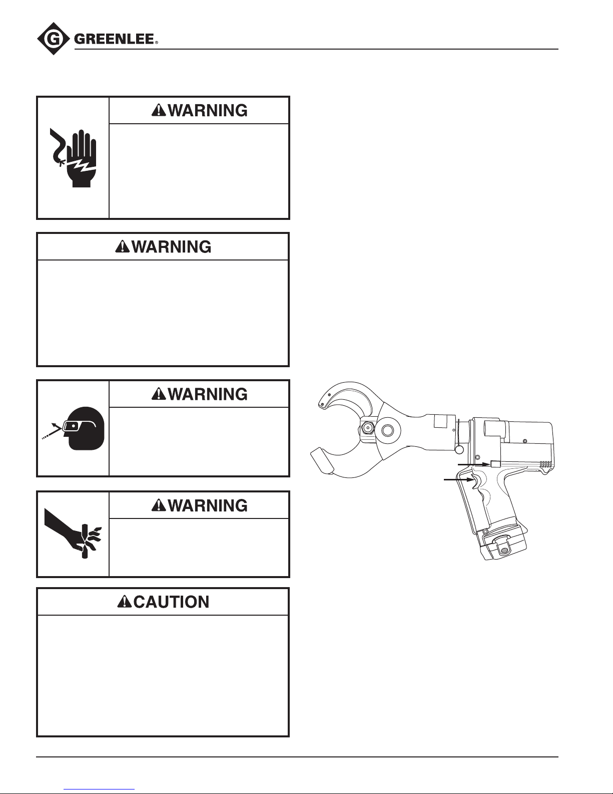
Operation
Pull trigger to cut
Push to retract blades
Electric shock hazard:
This tool is not insulated. When using
this unit near energized electrical
lines, use proper personal protective
equipment.
Failure to observe this warning could
result in severe injury or death.
Electric shock hazard: The owner of this cutter
•
must be certain that all users of this tool are trained
in the applicable safety codes and standards
as well as in the safe use of this tool and its
accessories.
Do not cut cable under tension.
•
Failure to observe these warnings could result in
severe injury or death.
ESC85 Battery-powered Cable Cutter
Charging the Battery
Read the instructions supplied with the battery charger.
Testing the Battery
A ickering battery load display indicates a low charge
level. A constant light when the tool is in neutral also
indicates a low charge.
Note: It is normal for the battery load display to light at
both the beginning of a cutting cycle and at the point of
maximum pressure.
Cutting Cable
1. Position the cable in the open cutting head.
2. Pull the trigger. The blades will begin to close.
3. When the cut is completed, push the retract button
to return the ram. Hold the button until the ram
returns to the desired position.
Note: At any time during cutting, pushing the return
button will result in a complete return of the ram.
Wear eye protection when operating
or servicing this tool.
Failure to wear eye protection could
result in serious eye injury from ying
debris or hydraulic oil.
Keep hands away from closing
blades.
Failure to observe this warning could
result in severe injury or death.
Do not cut steel or ACSR. Cut only copper and
•
aluminum cable.
This tool is not designed for continuous use. After
•
30 to 40 cutting cycles, allow the tool to cool for 15
minutes.
Protect the tool from rain and moisture.
•
damage the tool and battery.
Failure to observe these precautions may result in
injury or property damage.
Water will
Greenlee / A Textron Company 4455 Boeing Dr. • Rockford, IL 61109-2988 USA • 815-397-7070
6
Page 7
Maintenance
ESC85 Battery-powered Cable Cutter
Each Operating Day
Before use:
1. Inspect blades for damage such as cracks, gouges,
or chips.
2. Inspect the tool for damage or leaks. Return a
damaged or leaking tool to an authorized Greenlee
service center.
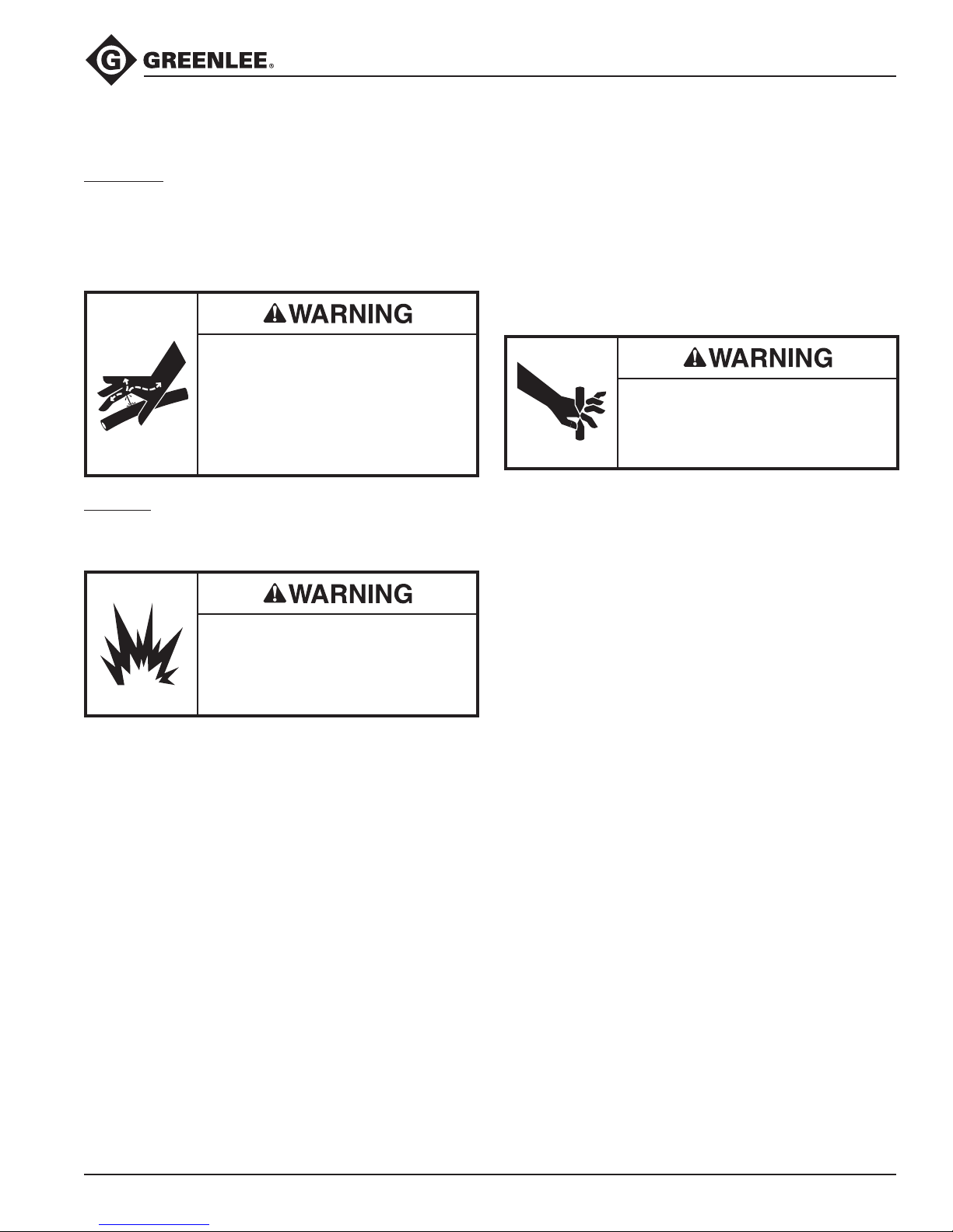
Skin injection hazard:
Do not use hands to check for
oil leaks. High pressure oil easily
punctures skin causing serious
injury, gangrene, or death. If injured,
seek medical help immediately to
remove oil.
After use:
1. Wipe all tool surfaces clean with a damp cloth and
mild detergent.
Do not use solvents or ammable
liquids to clean the tool body.
Solvents or ammable liquids could
ignite and cause serious injury or
property damage.
2. Fully retract the blades. Place the tool in the
carrying case. Store in a cool, dry place.
3. Charge the battery.
Monthly
1. Thoroughly clean all surfaces.
2. Check the oil level.
3. Oil the bolt joints.
Annually or Every 8000 Cutting Cycles
1. Change the hydraulic oil.
2. Return the tool to an authorized Greenlee service
center for inspection.
Keep hands away from closing
blades.
Failure to observe this warning could
result in severe injury or death.
Checking the Oil Level
1. Remove the two screws that retain the tank housing
cover.
2. Remove the tank housing cover.
3. Point the head downward and remove the oil plug.
Add oil if necessary.
4. Replace the oil plug and the tank housing cover.
Secure with screws.
Recommended Hydraulic Oils
AVIA® HVI 15
Shell Tellus T 15
Mobil® DTE 11M
NUTO® H 15
Greenlee / A Textron Company 4455 Boeing Dr. • Rockford, IL 61109-2988 USA • 815-397-7070
7
Page 8
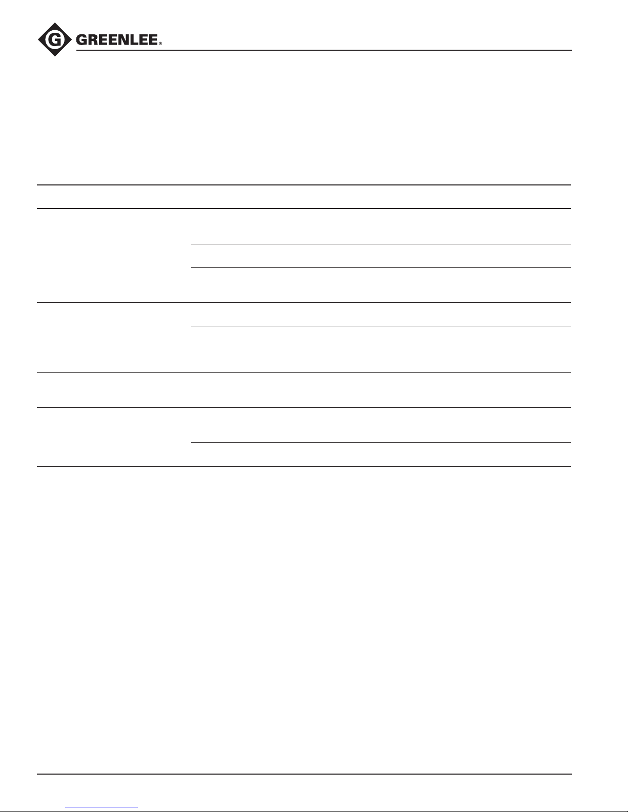
ESC85 Battery-powered Cable Cutter
Troubleshooting
Before You Begin
1. Make sure that the battery is charged. Recheck the battery after several minutes to make sure the battery is
holding its charge.
2. Use a nonflammable contact cleaner or pencil eraser to clean the electrical contacts on the battery and tool.
3. Reinstall the battery and check the tool again.
Problem Probable Cause Probable Remedy
Tool is inoperative. Dirt, contaminants, etc., in ram area or
wedged between the blades of tool.
Tool battery contacts damaged. Reform contacts.
Tool components worn or damaged. Return tool to an Greenlee
Cutting blades stop during
operation.
Battery load display ashes
constantly.
Tool loses oil. Damaged internal seal. Return tool to an Greenlee
Oil level is low. Check oil level. Rell reservoir.
Air in hydraulic system. Pull trigger and hold retract button
Battery charge low. Charge or replace battery.
Oil plug not installed properly. Rell reservoir and replace plug.
Clean tool.
Authorized Service Center.
simultaneously. Hold for approximately 10 seconds.
Authorized Service Center.
Greenlee / A Textron Company 4455 Boeing Dr. • Rockford, IL 61109-2988 USA • 815-397-7070
8
Page 9

Disassembly
ESC85 Battery-powered Cable Cutter
Main Components
1. Remove the battery.
2. Loosen two screws (13).
3. Unscrew and remove the head assembly.
4. Remove piston (16). Replace piston O-ring (14) and
piston backup ring (15).
5. Unscrew two tank cover screws (53) and remove the
tank cover (58).
6. Remove the hydraulic reservoir plug (76) and drain
the hydraulic uid.
7. Reinstall the plug.
8. Remove the remaining housing screws (51, 53).
9. Remove the right housing half (59).
10. Remove the trigger cover (56).
11. Lift the pump/motor assembly and circuit card
from the left housing half (60). Lift the LED from its
housing (8).
12. Slide a plastic bag over the circuit card and elec-
tronic subassemblies. Tape the bag shut to protect
the subassemblies from hydraulic oil and other
contamination.
13. Unscrew the shoulder bolt (108) and remove the
release lever (111).
14. Remove screws (100) and separate the gear
housing/motor subassembly from the pump
housing.
Pump
1. Use a hooked tool to remove the reservoir O-ring
(80). Gently tug it over the reservoir.
2. Remove the reservoir (74).
3. Remove the pump piston (152).
4. Remove the screw plug (151), washer (153), pump
piston (150), valve stem (156), and spring (155).
Replace the sealing washer (154).
5. Use a piece of tape to mark the side of the relief
that is facing up. (This is a reference point for
reassembly). Remove the unloading valve by
unscrewing the plug (126).
6. Remove the feeder tube subassembly by unscrewing the feeder tube (78). Replace the oil lter (77).
Remove metal chips from the magnet (82).
7. Remove the threaded bushing (72) and replace the
O-ring (73).
Motor, Gearbox, and Bearing
1. Remove the tamper-proof paper seal (95).
2. Remove two screws (92). Remove the end cap (98).
3. Apply pressure evenly at three points around the
ball bearing (91) and gently pry the bearing up to
remove it.
4. Remove the eccentric (99), grooved ball bearing
(97), and snap ring (96) subassembly from the shaft.
5. Remove four screws (93). Remove the mounting
block (101) from the gear housing (94).
6. Use a snap-ring removal tool to remove the snap
ring (96).
7. Unscrew four bolts (not numbered) from the gear
housing (94). Separate the gear housing from
the spacer (not numbered). Unscrew two llister
head screws (104) to separate the spacer from the
motor (90).
Greenlee / A Textron Company 4455 Boeing Dr. • Rockford, IL 61109-2988 USA • 815-397-7070
9
Page 10

Assembly
ESC85 Battery-powered Cable Cutter
Motor, Gearbox, and Bearing
1. Install two llister head screws (104) into the spacer
(not numbered) and motor (90). Tighten the screws.
2. Install four screws (not numbered) into the gear
housing (94). Tighten the screws.
3. Install four screws (93) into the mounting block (101)
and gear housing (94). Tighten the screws.
4. Replace the grooved ball bearing (97) and snap ring
(96) subassembly.
5. Replace the eccentric (99). Use a ber mallet to
tap the eccentric onto the shaft. Replace the ball
bearing (91).
6. Align the end cap (98). Use a ber mallet to tap the
cover until it is ush on the mounting block (101).
Install two screws (92).
7. Align the gear housing/motor subassembly so that
the pump piston (152) extends through the mounting block (101) and makes contact with the grooved
bearing (97). Locate and start the screws (108)
through the mounting block and into the pump
housing. Tighten the screws.
Pump
1. Insert the pump piston (152) into the pump housing.
2. Insert the seal (122) and unloading valve assembly
into the pump housing. Grasp the needle valve
subassembly by the pressure relief (126) and twist it
several turns clockwise. Stop when the piece of
tape is facing up.
3. Assemble the pump piston (150), valve stem (156),
washer (153), spring (155), and screw plug (151).
Be sure to replace the sealing washer (154).
Torque the screw plug (151) to 101 Nm (75 ft-lb).
4. Install the release lever (111) so that the forked end
engages the unloading valve subassembly between
the pressure relief (126) and the support ring (127).
Install the screw (108) and washer (109).
5. Insert the threaded bushing (79) and feed tube
subassembly (77, 78, 82). Screw in until snug.
6. Install the reservoir (74). Slip the O-ring (80) over
the reservoir. Using a hooked tool, carefully slip the
O-ring over the lip of the pump housing.
7. Insert the plug (76) into the reservoir.
Main Components
1. Remove the protective plastic bag from the
electronics subassembly. Insert the LED into the
LED bushing (8).
2. Lay the gear housing/motor subassembly into the
left half of the housing. Insert the circuit board into
the circuit board slot so that the wires and chip face
in the direction of the trigger.
3. Lay the wires into the case. Be sure that the wires
will not be pinched.
4. Guide the wires for the battery clip so that the
battery wires lay on top of the electronics box;
install the battery clip so the red wire is upward.
5. Install the trigger cover (56). Press and release the
trigger to be sure that it operates freely.
6. Locate the right housing half (59) on top of the left
housing half (60). Check for pinched wires.
7. Install the housing screws (51, 53).
Note: The handle screw (51) must engage the
nut (52).
8. Install piston (30) with O-ring (14) and backup ring
(15).
9. Install spring (20) over piston rod (19) and slide into
yoke (25).
10. Place bearing block (21) into piston rod end.
Compress spring and install socket head cap screw
(18).
11. Lubricate bearing surface of blades (26) with
Molykote grease. Slide blades between yoke (25)
and install clevis pin (27) with pin head on opposite
side, as machined for handle (32).
12. Install hex jam nuts (28) to clevis pin. Do not overtighten. Lock jam nuts to each other.
13. Install links (22), clevis pins (23) and retaining rings
(24) to blades (26).
14. Install blade guide (29) with socket head cap
screws (30).
15. Clamp the head assembly into a vise with the
reservoir plug facing upward. Remove the ll plug
(76) and ll the reservoir with hydraulic oil.
16. Install the battery.
17. Squeeze the trigger while pressing the release lever
for 45 to 60 seconds. Fill the reservoir with hydraulic
oil. Replace the ll plug (76).
18. Replace the tank cover (58) and tank cover
screws (53).
19. Run the blades out until they overlap. Use a feeler
gage and check the gap between the blades at
the blade guide end. If the gap is more than .003"
add a shim between guide and on the side of the
blade.
.003/.002".
Use a shim that will bring the gap down to
Greenlee / A Textron Company 4455 Boeing Dr. • Rockford, IL 61109-2988 USA • 815-397-7070
10
Page 11
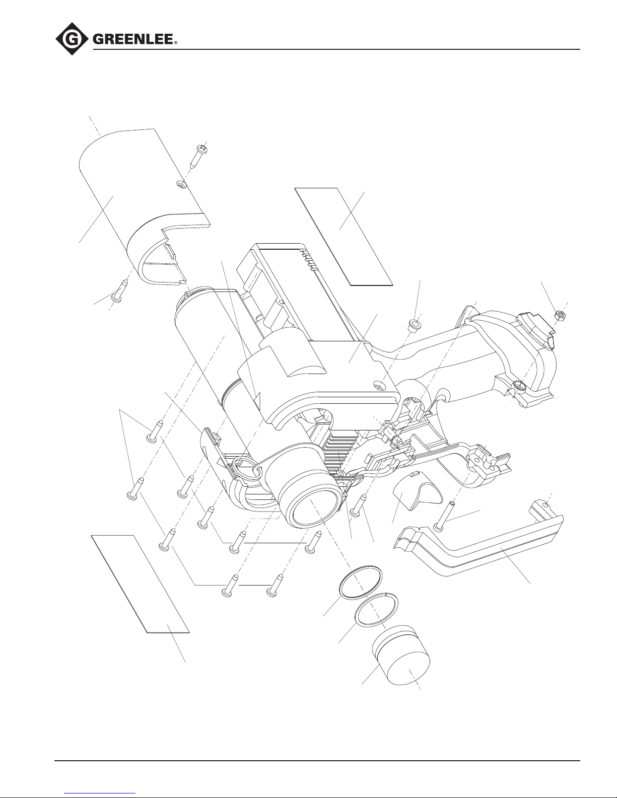
Illustration
57
51
56
53
16
15
14
9
11
53
59
52
8
60
10
12
58
53
ESC85 Battery-powered Cable Cutter
Greenlee / A Textron Company 4455 Boeing Dr. • Rockford, IL 61109-2988 USA • 815-397-7070
11
Page 12
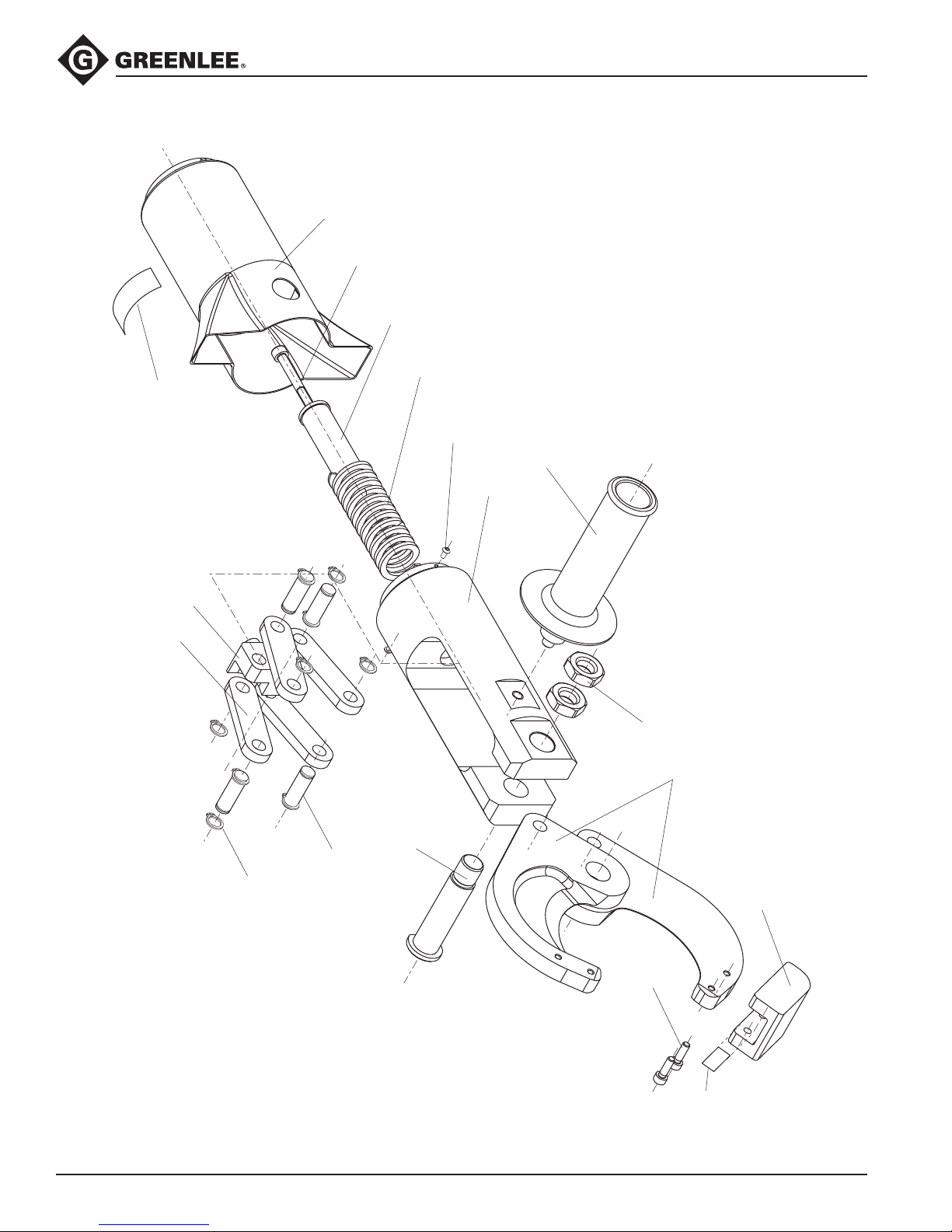
Illustration
24
23
27
22
21
31
17
18
19
20
13
25
32
28
26
30
29
User-added
shim
if required
ESC85 Battery-powered Cable Cutter
Greenlee / A Textron Company 4455 Boeing Dr. • Rockford, IL 61109-2988 USA • 815-397-7070
12
Page 13
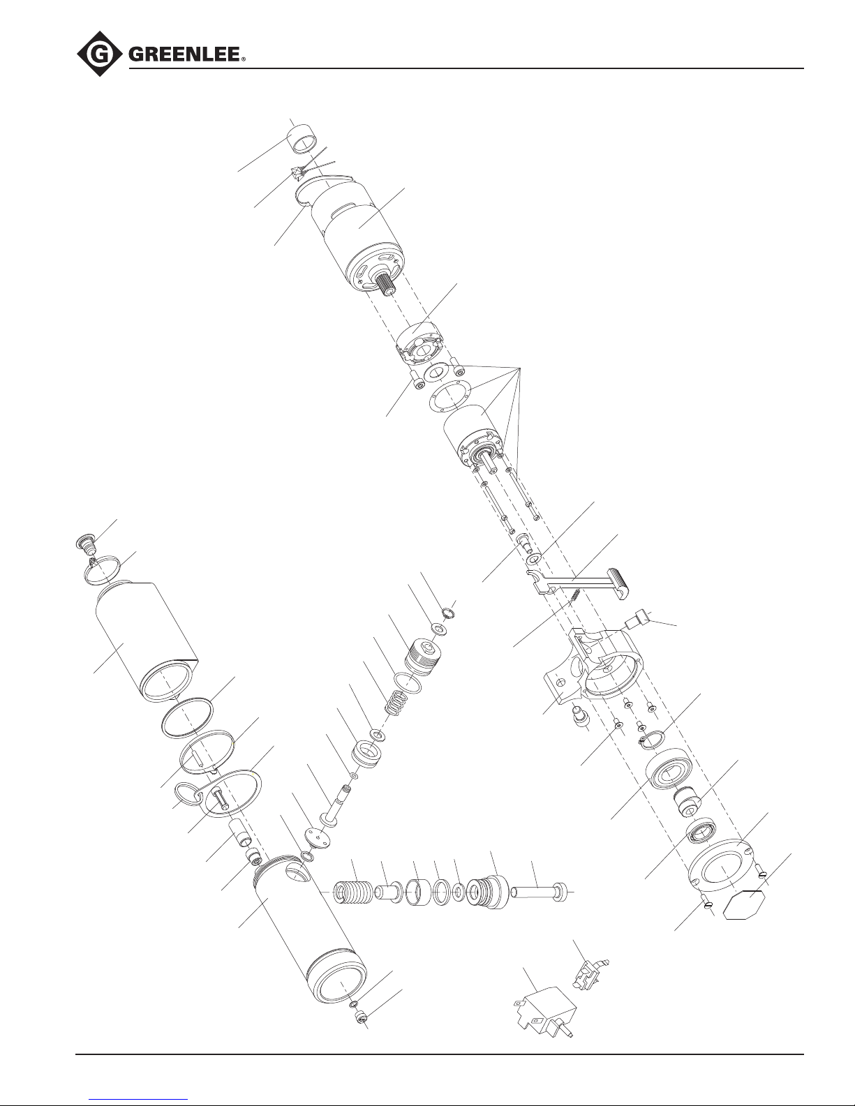
Illustration
72
73
83
79
81
70
80
71
76
74
82
75
77
78
92
91
97
93
101
108
104
106
107
105
90
102
96
98
99
95
100
111
109
94
155
156
150
153
152
151
154
140
141
128
129
122
123
124
120
121
130
125
126
127
110
ESC85 Battery-powered Cable Cutter
13
Greenlee / A Textron Company 4455 Boeing Dr. • Rockford, IL 61109-2988 USA • 815-397-7070
Page 14

ESC85 Battery-powered Cable Cutter
Parts List
Key Part No. Description Qty
8 50042416 Bushing LED ............................................................................................. 1
9 50071769 Circuit board, programmed ....................................................................... 1
10 52020649 Decal, identication ................................................................................... 1
11 52020650 Decal, warning .......................................................................................... 1
12 50062140 Decal, pinch hazard .................................................................................. 1
13 50032950 Screw ........................................................................................................ 2
14 50041924 O-ring ........................................................................................................ 1
15 50041940 Piston backup ring .................................................................................... 1
16 52020648 Piston ....................................................................................................... 1
17 50067656 Decal, warning .......................................................................................... 1
52020634 Cutting head (includes items 13, 18–32)
18 52020645 M6 x 55 mm socket head cap screw ................................................... 1
19 52020641 Piston rod............................................................................................. 1
20 50058258 Return spring ....................................................................................... 1
21 52020640 Bearing block ....................................................................................... 1
22 52020637 Link ...................................................................................................... 4
23 50120964 Clevis pin assembly ............................................................................. 4
24 Retaining ring (included in #23) ........................................................... 4
25 52020642 Yoke ..................................................................................................... 1
26 52020635 Blade .................................................................................................... 2
27 52020643 Clevis pin ............................................................................................. 1
28 52020644 M16 hex nut ......................................................................................... 2
29 52020639 Blade guide .......................................................................................... 1
30 50019210 M5 socket head cap screw .................................................................. 2
31 52020638 Shrink cover ......................................................................................... 1
32 52020646 Handle .................................................................................................. 1
50013459 Housing unit (green) (includes items 51–60)
51 50042203 Screw ................................................................................................... 1
52 50042211 Nut ....................................................................................................... 1
53 50042076 Screw ................................................................................................. 12
56 Switch cover (black) ............................................................................. 1
57 Trigger guard ........................................................................................ 1
58 Reservoir cover .................................................................................... 1
59 Housing, right side ............................................................................... 1
60 Housing, left side ................................................................................. 1
Greenlee / A Textron Company 4455 Boeing Dr. • Rockford, IL 61109-2988 USA • 815-397-7070
14
Page 15

ESC85 Battery-powered Cable Cutter
Parts List (cont’d)
Key Part No. Description Qty
50013467 Pump housing, reservoir assembly (includes items 70–83)
70 50103407 Ring tie ................................................................................................. 1
71 50071777 Cable tie ............................................................................................... 1
72 50041444 Threaded bushing ................................................................................ 1
73* 50041436 O-ring ................................................................................................... 1
74 50058738 Hydraulic reservoir ............................................................................... 1
75 50041983 Ring ...................................................................................................... 1
76 50058789 Reservoir plug ...................................................................................... 1
77 50058800 Filter ..................................................................................................... 1
78 50058827 Filter adapter ........................................................................................ 1
79 50058851 Threaded bushing ................................................................................ 1
80* 50058860 O-ring ................................................................................................... 1
81 50058290 Attachment ring ................................................................................... 1
82 50058983 Magnet ................................................................................................. 1
83 50103644 Pump housing ...................................................................................... 1
50121758 Motor assembly (includes items 90–111)
90 52024659 Motor with gear .................................................................................... 1
91 50041380 Ball bearing .......................................................................................... 1
92 50041550 Screw ................................................................................................... 2
93 50041576 Screw ................................................................................................... 4
94 50015729 Gearbox ............................................................................................... 1
95 * 50041533 Seal ...................................................................................................... 1
96 50041517 Retaining ring ....................................................................................... 1
97 50041398 Grooved ball bearing ........................................................................... 1
98 50041088 End cap ................................................................................................ 1
99 50041231 Eccentric .............................................................................................. 1
100 50121839 Screw ................................................................................................... 2
101 50084022 Eccentric case ..................................................................................... 1
102 50013513 Gearbox ............................................................................................... 1
104 50103385 Screw ................................................................................................... 2
105 ** Spacer.................................................................................................. 1
106 ** Ground strap ........................................................................................ 1
107 ** Capacitor ............................................................................................. 3
108 † Screw, socket head ............................................................................. 1
109 † Lock washer ......................................................................................... 1
110 † Spring .................................................................................................. 1
111 † Release lever ........................................................................................ 1
Greenlee / A Textron Company 4455 Boeing Dr. • Rockford, IL 61109-2988 USA • 815-397-7070
15
Page 16

ESC85 Battery-powered Cable Cutter
USA 800-435-0786 Fax: 800-451-2632
815-397-7070 Fax: 815-397-1865
Canada 800-435-0786 Fax: 800-524-2853
International +1-815-397-7070 Fax: +1-815-397-9247
4455 Boeing Drive • Rockford, IL 61109-2988 • USA • 815-397-7070
An ISO 9001 Company • Greenlee Textron Inc. is a subsidiary of Textron Inc.
www.greenlee.com
Printed in USA
Parts List (cont’d)
Key Part No. Description Qty
50015931 Relief valve assembly (includes items 120–130)
120 50058606 Washer ................................................................................................. 1
121* 50041347 O-ring ................................................................................................... 1
122* 50058622 Seal ...................................................................................................... 1
123 50053630 Valve seat ............................................................................................. 1
124 50058649 Plunger ................................................................................................. 1
125* 50058690 O-ring ................................................................................................... 1
126 50058711 Pressure relief ...................................................................................... 1
127 50058754 Support ring ......................................................................................... 1
128* 50058762 Retaining ring ....................................................................................... 1
129 50058770 Needle valve ........................................................................................ 1
130 50058940 Spring .................................................................................................. 1
50013475 Electrical assembly (includes items 140–144)
140 50041266 Switch .................................................................................................. 1
141 50041274 Battery contacts .................................................................................. 1
142 50063383 Circuit board, programmed ................................................................. 1
143 50058991 Wire (not shown) .................................................................................. 1
144 50059009 Wire (not shown) .................................................................................. 1
50013483 Piston pump assembly (includes items 150–156)
150 50058916 Pump piston......................................................................................... 1
151 50103652 Screw plug ........................................................................................... 1
152 50103709 Pump piston......................................................................................... 1
153* 50103695 Washer ................................................................................................. 1
154* 50103660 Sealing washer ..................................................................................... 1
155 50103679 Spring .................................................................................................. 1
156 50103687 Valve stem ............................................................................................ 1
* 50014080 Seal kit (includes items marked with an asterisk)
** 91871417 Capacitor assembly (includes items marked with double asterisks)
† 50118927 Release lever assembly (includes items marked with a †)
52020633 Case with inserts
50029991 12 V battery NiCd
50030469 12 V charger 110 VAC
50030477 12 V charger 220 VAC
50030485 12 V charger 12 VDC
 Loading...