

Page 1
INSTRUCTION MANUAL
MANUAL DE INSTRUCCIONES
MANUEL D’INSTRUCTIONS
BEDIENUNGSANLEITUNG
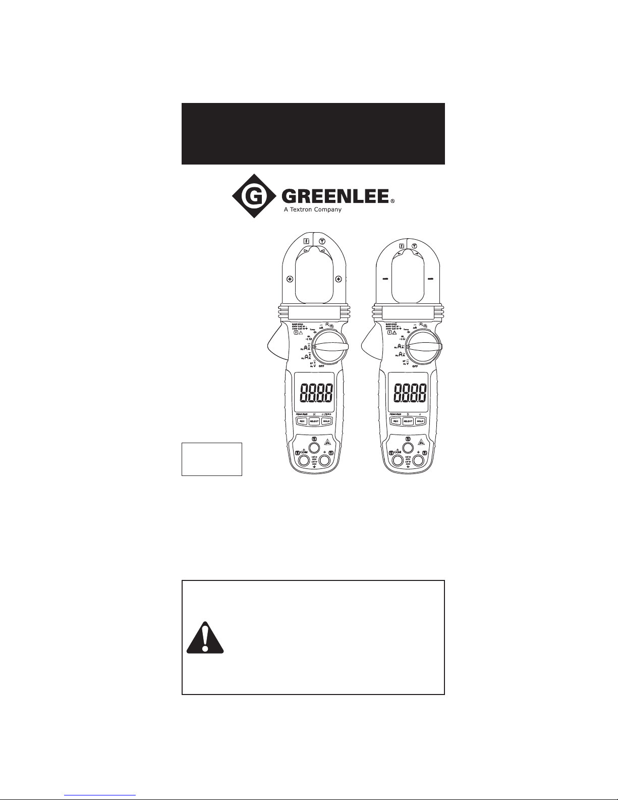
CM-660
CM-860
CM-960
CMH-600
CMI-600
Español.............23
...........43
Français
............63
Deutsch
Clamp Meters
Read and understand all of the instructions and safety information in
this manual before operating or servicing this tool.
Lea y entienda todas las instrucciones y la información sobre
seguridad que aparecen en este manual, antes de manejar estas
herramientas o darles mantenimiento.
Lire attentivement et bien comprendre toutes les instructions et
les informations sur la sécurité de ce manuel avant d’utiliser ou de
procéder à l’entretien de cet outil.
Vor Bedienung oder Wartung dieses Messgerätes bitte alle
Anweisungen und Sicherheitsinformationen in diesem Handbuch
genau durchlesen und beachten.
52066382 REV 1 © 2013 Greenlee Textron Inc. 12/13
Find Quality Products Online at: [email protected]
www.GlobalTestSupply.com
Page 2
Description
The Greenlee CM-660, CM-860, CM-960, CMH-600, and CMI-600 Clamp Meters are
hand-held testing devices with the following measurement capabilities: AC and DC
voltage, AC current, AC current AmpTip™, frequency, non-contact electric field (EF)
detection, and resistance. They also check diodes and verify continuity. These meters
are designed to be placed on or removed from insulated or uninsulated conductors.
Additional functionality specific to each model includes:
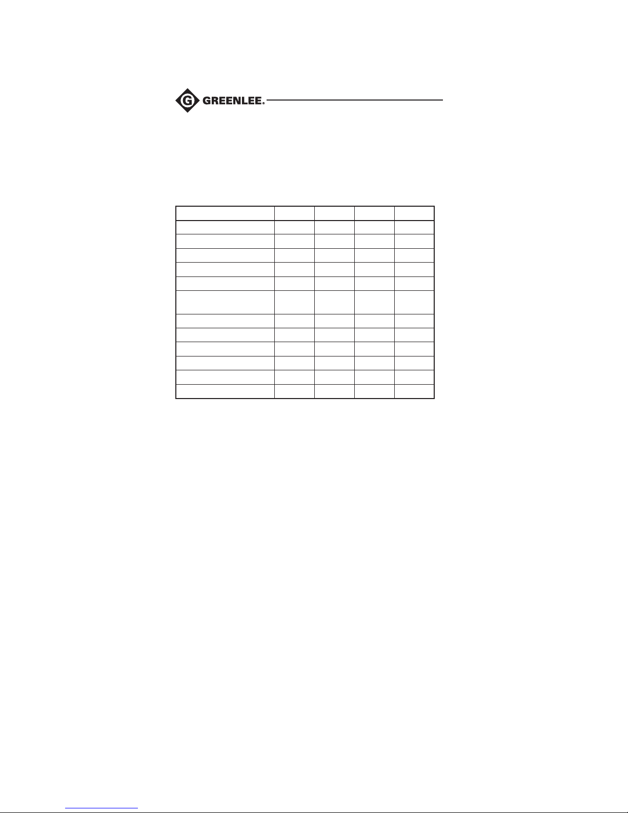
Function CMI-600 CM-960 CMH-600 CM-860
AC + DC Voltage • •
DC Current AmpTip™ • •
DC + AC Current AmpTip™ • •
DC Current • •
µDC Current • •
Temperature (K-style
thermocouple)
Motor Rotation • •
Phase Rotation • •
Peak RMS Capture • • •
Capacitance • • • •
Backlight • • • •
Zero Mode • • • •
Other capabilities include:
• Hold Mode to capture the present LCD value
• Record Minimum, Maximum, or Average Mode
• Intelligent Auto Power Off
• Automatic ranging
• •
Safety
Safety is essential in the use and maintenance of Greenlee tools and equipment. This
instruction manual and any markings on the tool provide information for avoiding
hazards and unsafe practices related to the use of this tool. Observe all of the safety
information provided.
Purpose of This Manual
This instruction manual is intended to familiarize all personnel with the safe operation
and maintenance procedures for the Greenlee CM-660, CM-860, CM-960, CMH-600,
and CMI-600 Clamp Meters.
2
Find Quality Products Online at: [email protected]
www.GlobalTestSupply.com
Page 3
CM-660 • CM-860 • CM-960 • CMH-600 • CMI-600
Important Safety Information
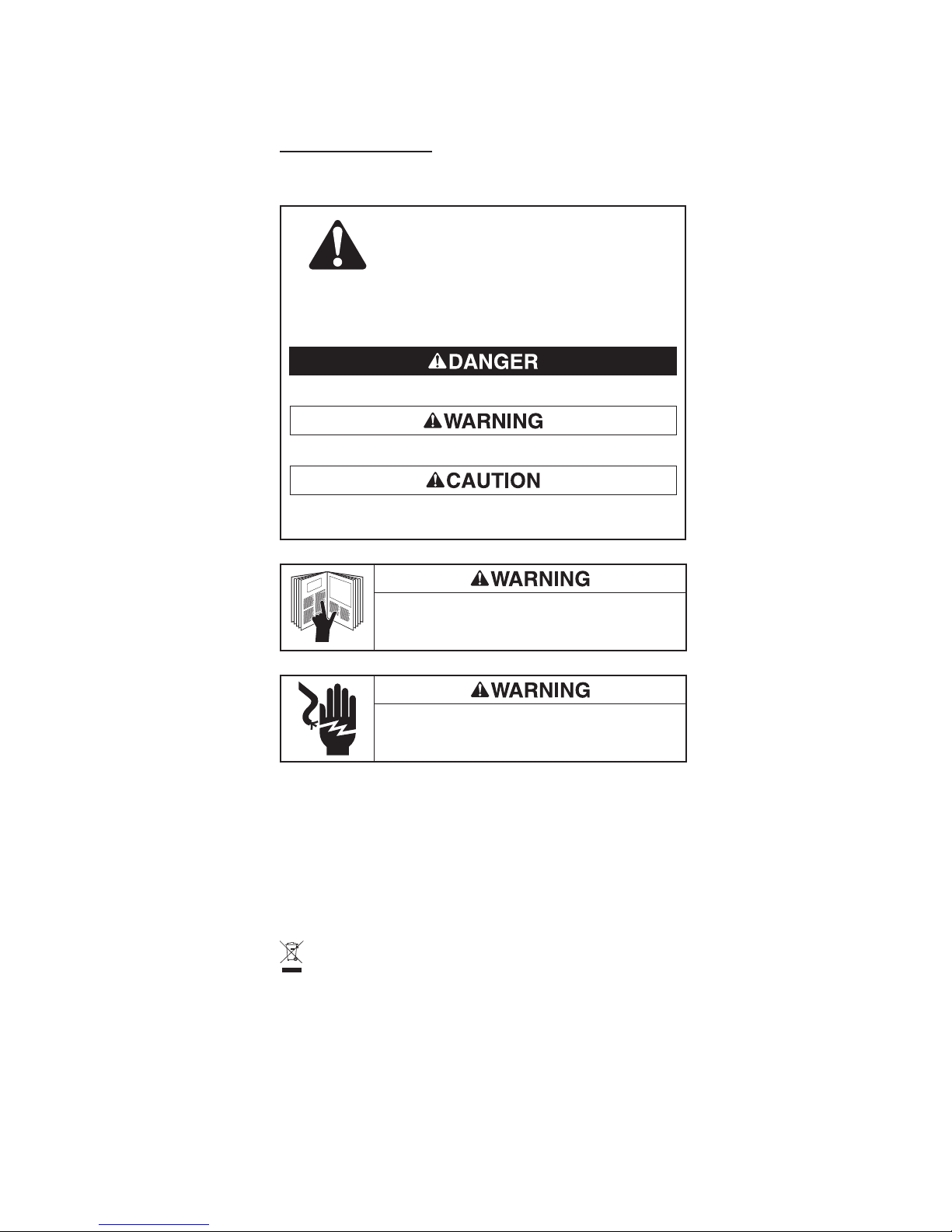
SAFETY ALERT SYMBOL
This symbol is used to call your attention to hazards or unsafe practices which
could result in an injury or property damage. The signal word, defined below,
indicates the severity of the hazard. The message after the signal word provides
information for preventing or avoiding the hazard.
Immediate hazards which, if not avoided, WILL result in severe injury or death.
Hazards which, if not avoided, COULD result in severe injury or death.
Hazards or unsafe practices which, if not avoided, MAY result in injury or property
damage.
Read and understand this material before operating or servicing
this equipment. Failure to understand how to safely operate this
tool could result in an accident causing serious injury or death.
Electric shock hazard:
Contact with live circuits could result in severe injury or death.
Do not discard this product or throw away!
All specifications are nominal and may change as design improvements occur. Greenlee Textron Inc.
shall not be liable for damages resulting from misapplication or misuse of its products.
® Registered: The color green for electrical test instruments is a registered trademark of
TextronInnovations Inc.
AmpTip is a trademark of BTC.
KEEP THIS MANUAL
3
Find Quality Products Online at: [email protected]
www.GlobalTestSupply.com
Page 4
Important Safety Information
Electric shock and fire hazard:
• Do not expose this unit to rain or moisture.
• Do not use the unit if it is wet or damaged.
• Clamp meter, test leads or any other clamp accessory, when used to make a measurement, create a System. The System is rated for CAT III 600 V or CAT IV 300V
when using the test leads or accessories provided with the meter. The System CAT
and voltage rating is limited by the lowest rated component in the System when
using test leads or accessories not provided with the meter.
• Inspect the test leads or accessory before use. They must be clean and dry, and
the insulation must be in good condition. Do not use the test lead if the contrasting
inner layer of insulation is visible.
• Use this unit for the manufacturer’s intended purpose only, as described in this
manual. Anyotheruse can impair the protection provided by the unit.
Failure to observe these warnings could result in severe injury or death.
Electric shock hazard:
• Do not apply more than the rated voltage between any two input terminals, or
between any input terminal and earth ground.
• Keep hands and fingers below the barriers on the test leads and the clamp meter
body.
Failure to observe these warnings could result in severe injury or death.
Electric shock hazard:
• Do not operate with the case open.
• Before opening the case, remove the test leads from the circuit and shut off the unit.
Failure to observe these warnings could result in severe injury or death.
4
Find Quality Products Online at: [email protected]
www.GlobalTestSupply.com
Page 5
CM-660 • CM-860 • CM-960 • CMH-600 • CMI-600
Important Safety Information
Electric shock hazard:
• Unless measuring voltage, current, or frequency, shut off and lock out power. Make
sure that all capacitors are discharged. Voltage must not be present.
• Set the selector and connect the test leads so that they correspond to the intended
measurement. Incorrect settings or connections can result in incorrect measurements or damage to the unit.
• Using this unit near equipment that generates electromagnetic interference can
result in unstable or inaccurate readings.
Failure to observe these warnings could result in severe injury or death.
Electric shock hazard:
• Do not change the measurement function while the test leads are connected to a
component or circuit.
• Do not clamp the jaw around a conductor carrying a frequency greater than 400Hz.
The magnetic circuitry may reach a hazardous temperature if this frequency is
exceeded.
Failure to observe these precautions may result in injury and can damage the unit.
Electric shock hazard:
• Do not attempt to repair this unit. It contains no user-serviceable parts.
• Do not expose the unit to extremes in temperature or high humidity. Refer to
“Specifications.”
Failure to observe these precautions may result in injury and can damage the unit.
5
Find Quality Products Online at: [email protected]
www.GlobalTestSupply.com
Page 6
Identification
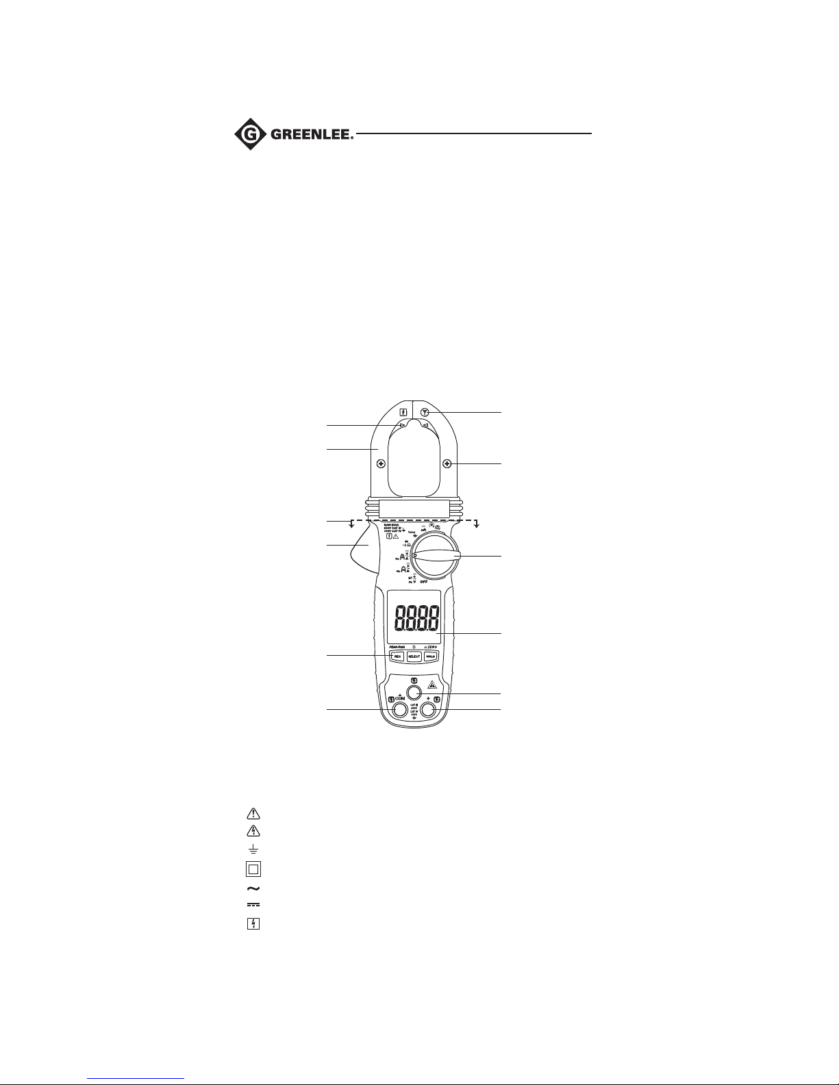
1. Antenna for non-contact EF detection
2. Jaw center indicator for best current accuracy; polarity indicator for DC amps
3. Selects a function or turns power off
4. LCD
5. Input jack for phase and motor rotation functions only
6. Positive input terminal; L2 input for motor and phase rotation
7. Negative, common, or ground input terminal; L1 input for motor and phase rotation
8. Refer to explanation under “Using the Features.”
9. Jaw lever
10. Keep hand or fingers below the dashed line during operation.
11. Jaw
12. Center indicator for AmpTip™ function
12
11
10
9
8
7
Symbols on the Unit
1
2
3
4
5
6
Warning—Read the instruction manual
Warning—Risk of electric shock
Earth ground
Double insulation
AC (alternating current)
DC (direct current)
Application around or removal from hazardous live conductors is permitted.
6
Find Quality Products Online at: [email protected]
www.GlobalTestSupply.com
Page 7
CM-660 • CM-860 • CM-960 • CMH-600 • CMI-600
Display Icons
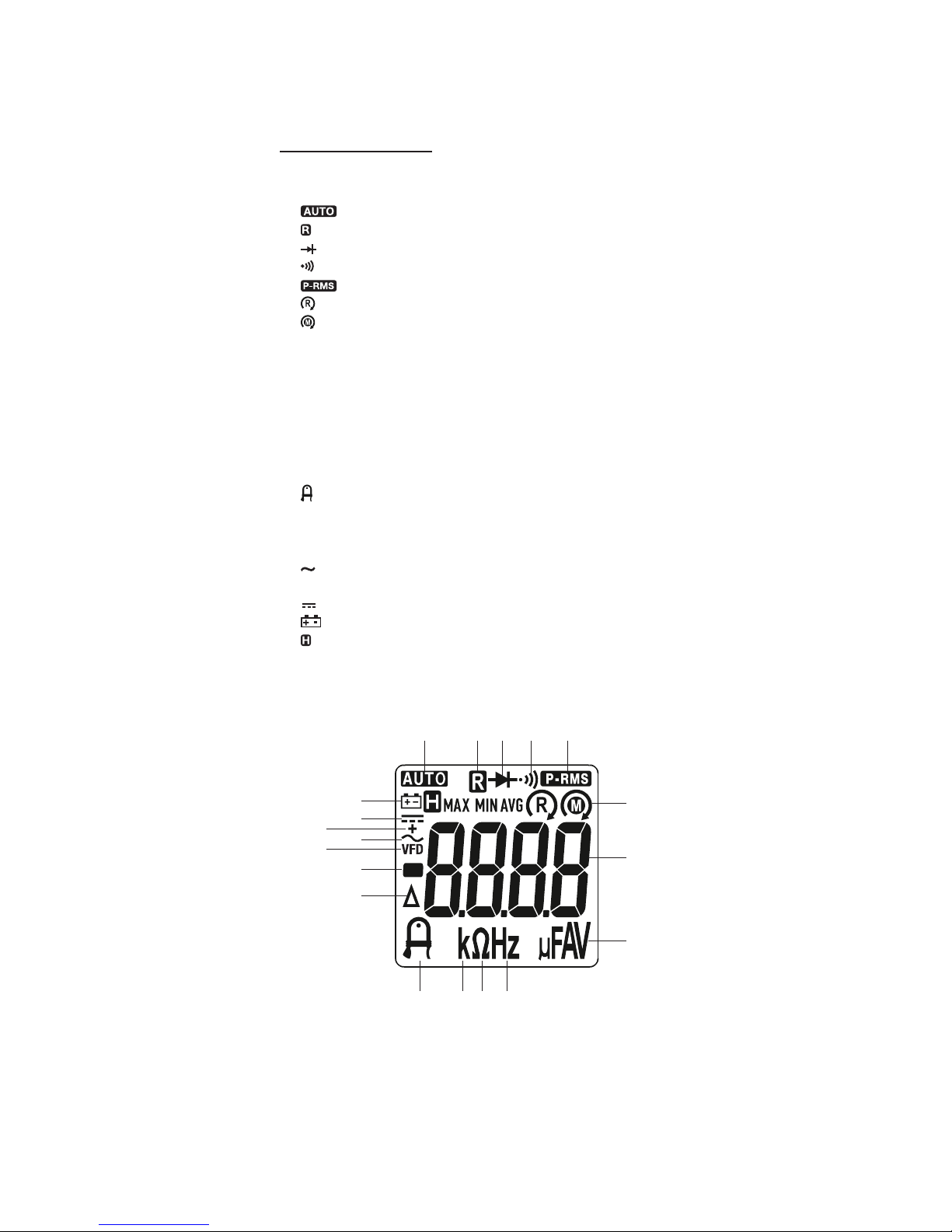
1. Automatic ranging is enabled.
2. Record function is enabled.
3. Diode
4. Continuity
5. PEAK-RMS mode is enabled.
6. Phase rotation main supply
7. Motor rotation
8. 8.8.8.8 Numeric display
9. µ Micro (10-6)
10. F Farad
11. A Ampere
12. V Volt
13. Hz Hertz (frequency in cycles per second)
14. Ω Ohm
15. k Kilo (103)
16. AmpTip™ function is enabled.
17. ∆ Relative zero function is enabled.
18. – Polarity indicator
19. VFD AC measurement with filter for accuracy on variable frequency drives
20. AC measurement is selected.
21. + AC + DC measurement is selected.
22. DC measurement is selected.
23. Low battery
24. Hold function is selected.
25. MAX Maximum value being displayed
26. MIN Minimum value being displayed
27. AVG Average value being displayed
1
23-27
22
21
20
19
18
17
16 15 14 13
2 3 4 5
6-7
8
9-12
7
Find Quality Products Online at: [email protected]
www.GlobalTestSupply.com
Page 8
Using the Features
All Models
• REC: Press momentarily to activate MAX/MIN/AVG recording mode. and “MAX
MIN AVG” appear on the display. The meter beeps when new maximum or minimum
reading is updated. The average reading is calculated over time. Press the button
momentarily to read the MAX, MIN and AVG readings in sequence. Press the button
for 1 second to exit MAX/MIN/AVG recording mode. APO is disabled automatically in
this mode.
• SELECT: Press momentarily to toggle between functions, measurement modes,
or display modes. The last used setting becomes the default when that function is
selected again. To change the default, select a new setting. The setting will be stored
in nonvolatile memory.
• HOLD: Press momentarily to hold the present value on the display. Press again to exit
this mode.
• Intelligent Auto Power Off (APO): The meter automatically turns off after approxi-
mately 32 minutes of inactivity to extend battery life. Active meter function is specified
as: selector switch is rotated or pushbuttons are pressed; readings above 8.5% of
the range; non-OL readings for resistance, continuity, or diode function; non-zero
readings for Hz function; phase rotation segment moving. To wake up the meter from
Auto Power Off, press the SELECT button momentarily and release or turn the rotary
switch OFF and then back on. Always turn the rotary switch to the OFF position when
the meter is not in use.
CM-860, CM-960, CMH-600, and CMI-600 Only
• : Press the SELECT button for 1 second to toggle the LCD backlight. The back-
light automatically turns off after 32 seconds to extend battery life.
• ∆: Press the ∆ button for 1 second to toggle between zero and normal mode. In zero
mode the value on the LCD when the button is pressed becomes the offset. As the
input value changes, the offset is subtracted from the actual value. This modified
value is shown on the LCD.
Note: ∆ operation when DCA or DC + ACA functions are selected offsets any magnetic hysteresis in the jaw. If DCA or DC + ACA reading before measuring is not zero,
press the ∆ button for 1 second. The LCD will display “dc_0”. When this clears, the
meter is ready for operation. When measuring more than 5 A, this mode is disabled.
As an indication, the meter will beep three times.
CM-960, CMH-600, and CMI-600 Only
• PEAK-RMS: Press the PEAK-RMS button for 1 second to activate PEAK-RMS mode
to capture peak current or voltage in duration as short as 80 ms.
the display. Press the button for 1 second to exit PEAK-RMS mode. APO is disabled
automatically in this mode.
CMH-600 and CMI-600 Only
• and : If desired, press and hold the REC button while turning the meter ON
to enable the Beeper feature. If the segments indicate a clockwise movement, the
beeper sounds a single long beep per segment cycle. If the segments indicate a counterclockwise movement, the beeper sounds three short beeps per segment cycle.
• : Ensure the motor is electrically isolated from its power source. Press the
SELECT button momentarily to select Motor function. Connect the meter to the
motor as described in the “Settings Table” section of this manual. From the
perspective of looking down the shaft of the motor, spin it clockwise. If the meter
indicates a clockwise movement, the motor leads connected to L1, L2, and L3 of
the meter are T1, T2, and T3, respectively. If the meter indicates a counterclockwise movement, swap any two connects between the meter and motor. Then
retest.
• : Press the SELECT button momentarily to select Phase function. Connect the
meter to the phases as described in the “Settings Table” section of this manual.
If the meter indicates a clockwise movement, the phases connected to L1, L2,
and L3 of the meter are L1, L2, and L3, respectively. If the meter indicates a
counterclockwise movement, swap any two connects between the meter and
phases. Then retest.
8
appears on
Find Quality Products Online at: [email protected]
www.GlobalTestSupply.com
Page 9
CM-660 • CM-860 • CM-960 • CMH-600 • CMI-600
Using the Test Leads
Electric shock hazard:
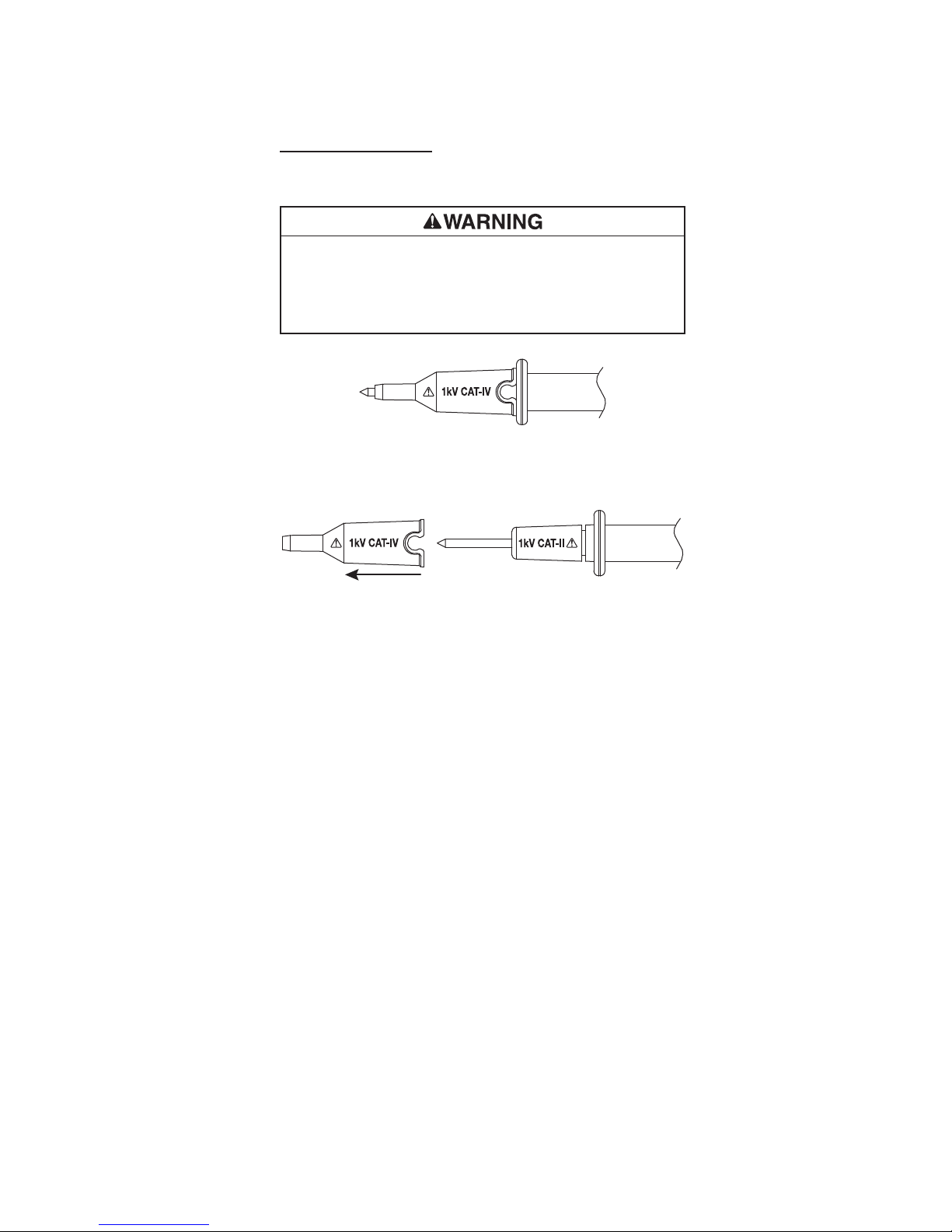
The test leads supplied with this product comply with safety standards that limit the
exposed length of the probe tip to 4 mm for measurement categories III and IV. These
test leads include a cap that must be in place when used in measurement category III
or IV applications.
Failure to observe this warning could result in severe injury or death.
Cap must be in place for measurement category III or IV applications.
Cap can be removed for measurement category I or II applications.
9
Find Quality Products Online at: [email protected]
www.GlobalTestSupply.com
Page 10
AC Measurement
AC measurements are usually displayed as RMS (root mean square) values. The RMS
value is equal to the value of a DC waveform, which would deliver the same power if it
replaced the time-varying waveform. Two AC measurement methods are average-responding RMS calibrated and true RMS-reading.
The average-responding RMS calibrated method takes the average value of the input
signal after full wave rectification, multiplies it by 1.11, and displays the result. This
method is accurate if the input signal is a pure sine wave.
The true RMS-reading method uses internal circuitry to read the true RMS value. This
method is accurate, within the specified crest factor limitations, whether the input signal
is a pure sine wave, square wave, triangle wave, half wave, or signal with harmonics.
The ability to read true RMS provides much more measurement versatility. The Greenlee
CM-660, CM-860, CM-960, CMH-600, and CMI-600 are true RMS meters.
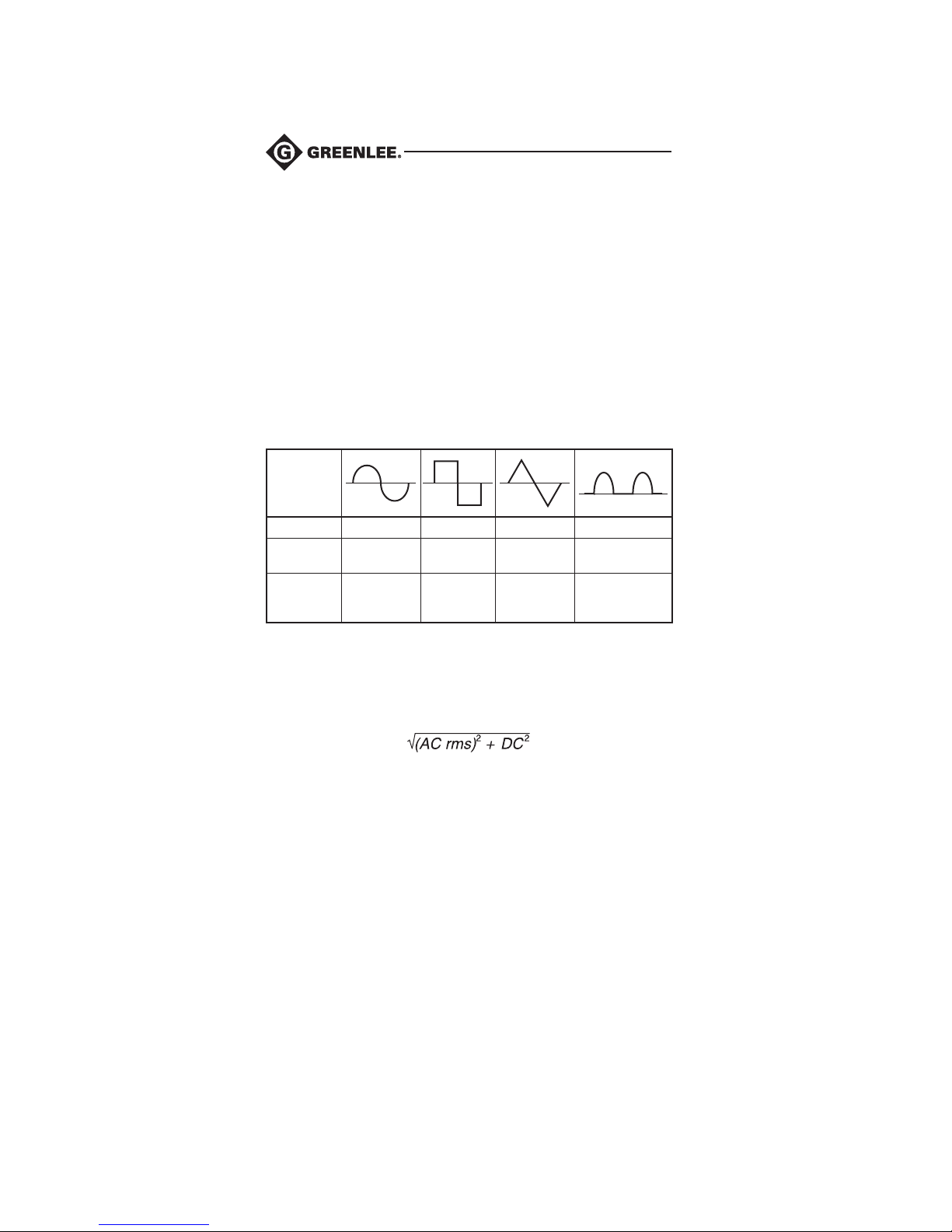
The Waveforms and Crest Factors table shows some typical AC signals and their RMS
values.
Waveforms and Crest Factors
Waveform
RMS Value 100 100 100 100
Average
Value
Crest
Factor*
(x)
* The crest factor is the ratio of the peak value to the RMS value; it is represented by
the Greek letter x.
90 100 87 64
1.414 1 1.73 2
AC + DC True RMS
AC + DC true RMS calculates both of the AC and DC components given by the
expression
when making measurements and responds accurately to the total effective RMS value
regardless of the waveform. Distorted waveforms with the presence of DC components
and harmonics may cause:
• Transformers, generators, and motors to overheat
• Circuit breakers to trip prematurely
• Fuses to blow
• Neutrals to overheat due to the triplen harmonics present on the neutral
• Bus bars and electrical panels to vibrate
CM-960 and CMI-600 can be set to display AC true RMS or AC + DC true RMS.
10
Find Quality Products Online at: [email protected]
www.GlobalTestSupply.com
Page 11
CM-660 • CM-860 • CM-960 • CMH-600 • CMI-600
AC Bandwidth
AC bandwidth is the range of frequencies over which AC measurements can be made
within the specified accuracy. It is the frequency response of the AC functions—not
of the frequency measurement functions. A meter cannot accurately measure the AC
value with frequency spectrums outside its bandwidth. Complex waveforms, noise,
and distorted waveforms contain frequency components that are much higher than the
fundamental; for example, high frequency noise on a 50/60 Hz power line.
Operation
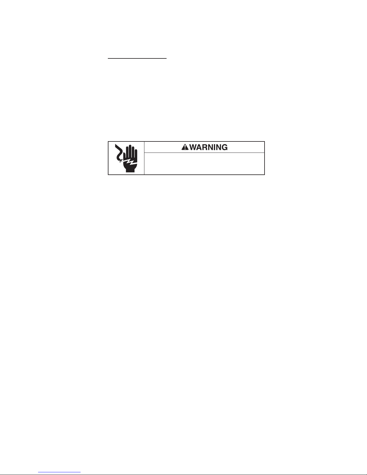
Electric shock hazard:
Contact with live circuits could result in severe injury or death.
Operating Procedure
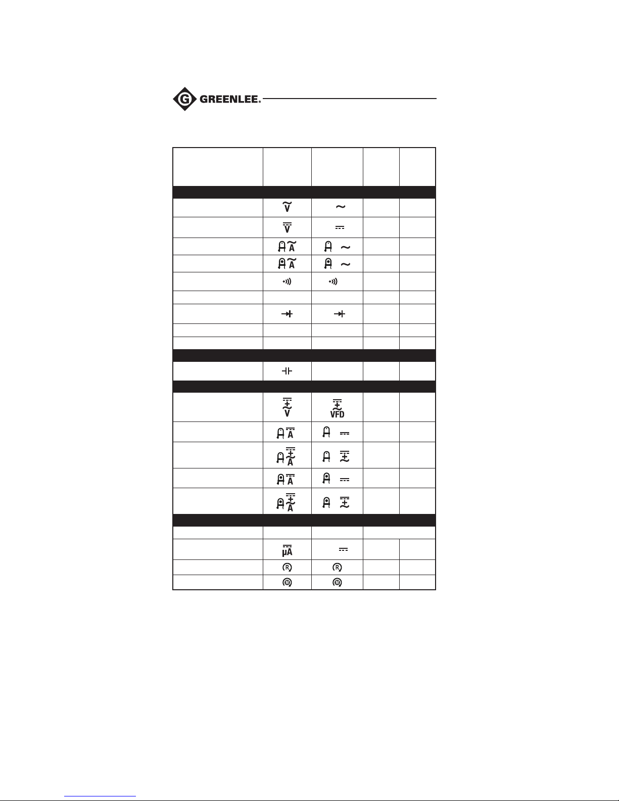
1. Refer to the “Settings Table.” Set the selector to the proper setting, press SELECT
(when instructed to do so), and connect the test leads to the meter.
2. Refer to “Typical Measurements” for specific measurement instructions.
3. Test the unit on a known functioning circuit or component.
• If the unit does not function as expected on a known functioning circuit, replace
the batteries.
4. Take the reading from the circuit or component to be tested.
11
Find Quality Products Online at: [email protected]
www.GlobalTestSupply.com
Page 12
Operation (cont’d)
Settings Table
To measure
this value …
Voltage (AC)
Set the
selector
to this
symbol…
ALL MODELS
These icons
appear on the
display …
V
Connect
the red
lead to…
+ COM
Connect
the black
lead to …
Voltage (DC)
Current, AmpTip™ (AC)
Current (AC)
Continuity
Resistance
Diode
Frequency
Electric Field (EF)*
CM-860, CM-960, CMH-600, and CMI-600 Only
Capacitance**
Voltage (AC + DC)
Current, AmpTip™ (DC)
Current, AmpTip™
(AC + DC)
Current (DC)
Current (AC + DC)
Temperature
Current (µDC)
Phase Rotation†
Motor Rotation†
* Use the top side of the stationary jaw, or for more precise measurements use a
probe in the COM terminal.
** Discharge capacitor before measurement. Refer to “Typical Measurements”
regarding polarized capacitors.
*** Thermocouple + connects to +, thermocouple – connects to COM.
† Yellow lead connects to L3.
Ω kΩ
Hz Hz
EF EF
CM-960 and CMI-600 Only
CMH-600 and CMI-600 Only
Temp C or F
V
V
µA
A
A
Ω
µF
A
A
A
A
+ COM
N/A N/A
N/A N/A
+ COM
+ COM
+ COM
+ COM
N/A COM
+ COM
+ COM
N/A N/A
N/A N/A
N/A N/A
N/A N/A
***
+ COM
+ COM
+ COM
12
Find Quality Products Online at: [email protected]
www.GlobalTestSupply.com
Page 13
CM-660 • CM-860 • CM-960 • CMH-600 • CMI-600
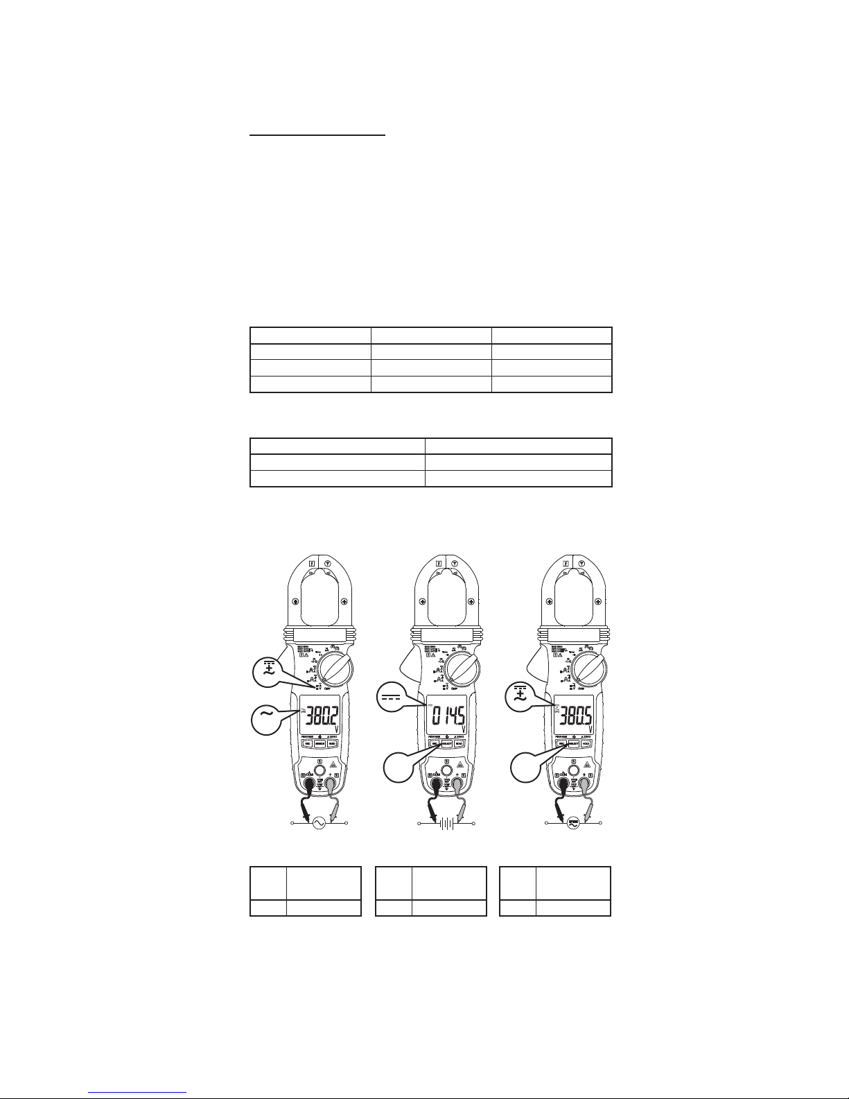
Typical Measurements and Accuracy
Refer to the “Specifications” section for operating conditions and temperature
coefficient.
Accuracy is specified as follows: ± (a percentage of the reading + a fixed amount) at
23 °C ± 5 °C (73.4 °F ± 9 °F).
Frequency must be within the specified bandwidth for non-sinusoidal waveforms.
Crestfactors, unless otherwise specified, are as follows:
• Crest factor < 2.5:1 at full scale
• Crest factor < 5.0:1 at half scale
Frequency
Function Sensitivity (Sine RMS)* Range
600 V 50 V
60.0 A AmpTip™ 40 A 50.00 Hz ~ 400.0 Hz
60.00 A, 600.0 A 40 A 50.00 Hz ~ 400.0 Hz
* DC bias must be less than 50% of the Sine RMS value.
Accuracy of Frequency Range
Display Range Accuracy
xx.xx ± (1.0% + 0.05 Hz)
xxx.x ± (1.0% + 0.5 Hz)
Voltage Measurement
5.00 Hz ~ 999.9 Hz
EF
VHz
VFD
AC Voltage
Range
Input Impedance: 10 MΩ, 100 pF nominal
Accuracy at
50 Hz to 60 Hz
600.0 ± (1.0% + 0.5 V)
DC Voltage
Range Accuracy
600.0 ± (1.0% + 0.5 V)
VFD
SELECTSELECT
AC + DC Voltage
(CM-960, CMI-600 only)
Accuracy at DC,
Range
50 Hz to 60 Hz
600.0 ± (1.2% + 0.7 V)
13
Find Quality Products Online at: [email protected]
www.GlobalTestSupply.com
Page 14
Typical Measurements and Accuracy (cont’d)
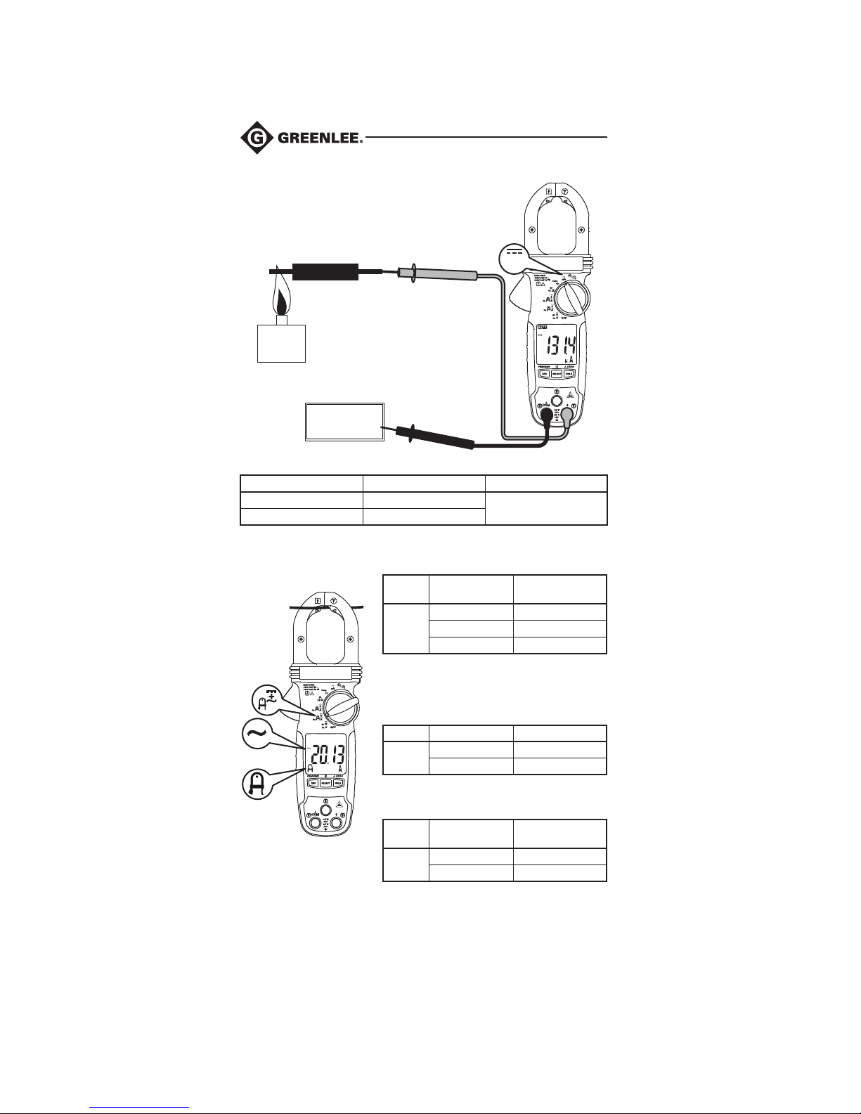
Current Measurement
µA DC Current
Flame Sensor
Pilot Flame
Control
Board
μDC Current (CMH-600 and CMI-600 only)
Range Accuracy Burden Voltage
200.0 μA ± (1.0% + 0.5 μA)
2000 μA ± (1.0% + 5 μA)
AmpTip™ Function
Hz
A
AmpTip™ AC Current
Range Accuracy Range
60.00 A
* For CM-660, CM-860, and CMH-600 only.
** For CM-960 and CMI-600 only, induced error for
adjacent current carrying conductors is < 0.01 A/A.
AmpTip™ DC Current (CM-960 and CMI-600 only)
Range Accuracy Range Accuracy†
60.00 A
µA
3.5 mV/μA
Accuracy at
50 Hz to 60 Hz**
< 0.20 A* unspecified
0.00 A to 3.99 A ± (1.5% + 0.15 A)
4.00 A to 60.00 A ± (1.5% + 0.05 A)
0.00 A to 3.99 A ± (2.0% + 0.15 A)
4.00 A to 60.00 A ± (2.0% + 0.05 A)
AmpTip™ DC + AC Current
(CM-960 and CMI-600 only)
Range
60.00 A
† Induced error for adjacent current carrying conductors is < 0.01 A/A.
Note: Use Δ if there is an offset before the measurement is taken.
14
Find Quality Products Online at: [email protected]
www.GlobalTestSupply.com
Accuracy
Range
0.00 A to 3.99 A ± (2.0% + 0.17 A)
4.00 A to 60.00 A ± (2.0% + 0.07 A)
Accuracy at DC,
50 Hz to 60 Hz†
Page 15
CM-660 • CM-860 • CM-960 • CMH-600 • CMI-600
Typical Measurements and Accuracy (cont’d)
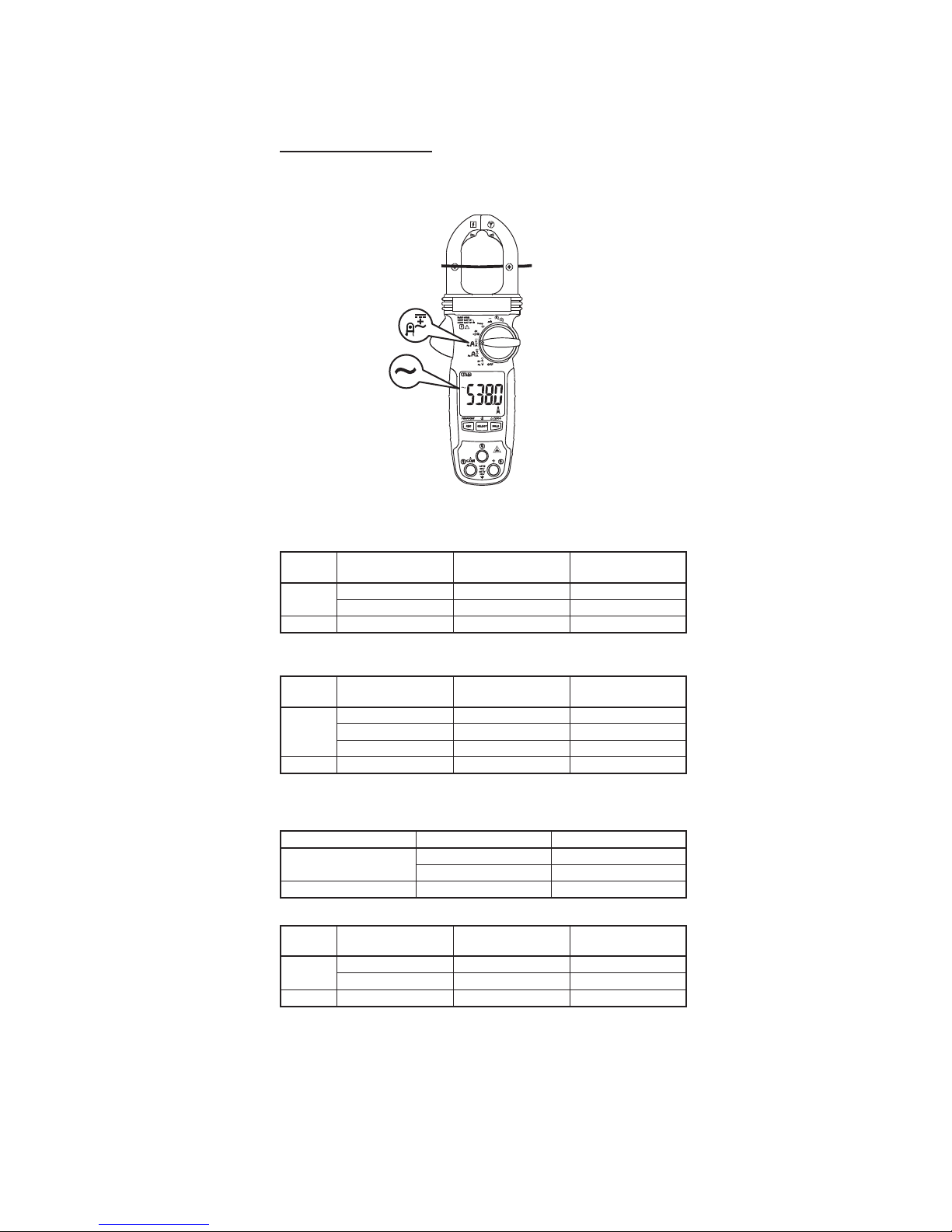
Current Measurement
(cont’d)
AC and DC Clamp
Hz
A
AC Current (CM-960 and CMI-600 only)
Range Accuracy Range
60.00 A
600.0 A 60.0 A to 600.0 A ± (1.8% + 0.5 A) ± (2.0% + 0.5 A)
* Maximum crest factor < 2:1 at full scale and < 4:1 at half scale.
AC Current (CM-660, CM-860, and CMH-600 only)
Range Accuracy Range
60.00 A
600.0 A 60.0 A to 600.0 A ± (1.8% + 0.5 A) ± (2.0% + 0.5 A)
* For any measurement, when the conductor is not positioned on the center of the
jaws, add 2.0% to the accuracy for position error.
DC Current (CM-960 and CMI-600 only)
AC + DC Current (CM-960 and CMI-600 only)
Range Accuracy Range
60.00 A
600.0 A 60.0 A to 600.0 A ± (2.2% + 0.5 A) ± (2.7% + 0.7 A)
0.00 A to 8.99 A ± (1.8% + 0.15 A) ± (2.0% + 0.15 A)
9.00 A to 60.00 A ± (1.8% + 0.05 A) ± (2.0% + 0.05 A)
0.00 A to 0.19 A unspecified unspecified
0.20 A to 5.99 A ± (1.8% + 0.15 A) ± (2.0% + 0.15 A)
6.00 A to 60.00 A ± (1.8% + 0.05 A) ± (2.0% + 0.05 A)
Range Accuracy Range Accuracy†
60.00 A
600.0 A 60.0 A to 600.0 A ± (2.0% + 0.5 A)
0.00 A to 8.99 A ± (2.2% + 0.15 A) ± (2.7% + 0.17 A)
9.00 A to 60.00 A ± (2.2% + 0.05 A) ± (2.7% + 0.07 A)
Accuracy at
50 Hz to 100 Hz*†
Accuracy at
50 Hz to 100 Hz*†
0.00 A to 8.99 A ± (2.0% + 0.15 A)
9.00 A to 60.00 A ± (2.0% + 0.05 A)
Accuracy at
50 Hz to 100 Hz†
Accuracy at
100 Hz to 400 Hz*†
Accuracy at
100 Hz to 400 Hz*†
Accuracy at
100 Hz to 400 Hz†
† Induced error for adjacent current carrying conductors is < 0.01 A/A.
Note: Use Δ if there is an offset before the measurement is taken.
15
Find Quality Products Online at: [email protected]
www.GlobalTestSupply.com
Page 16
Typical Measurements and Accuracy (cont’d)
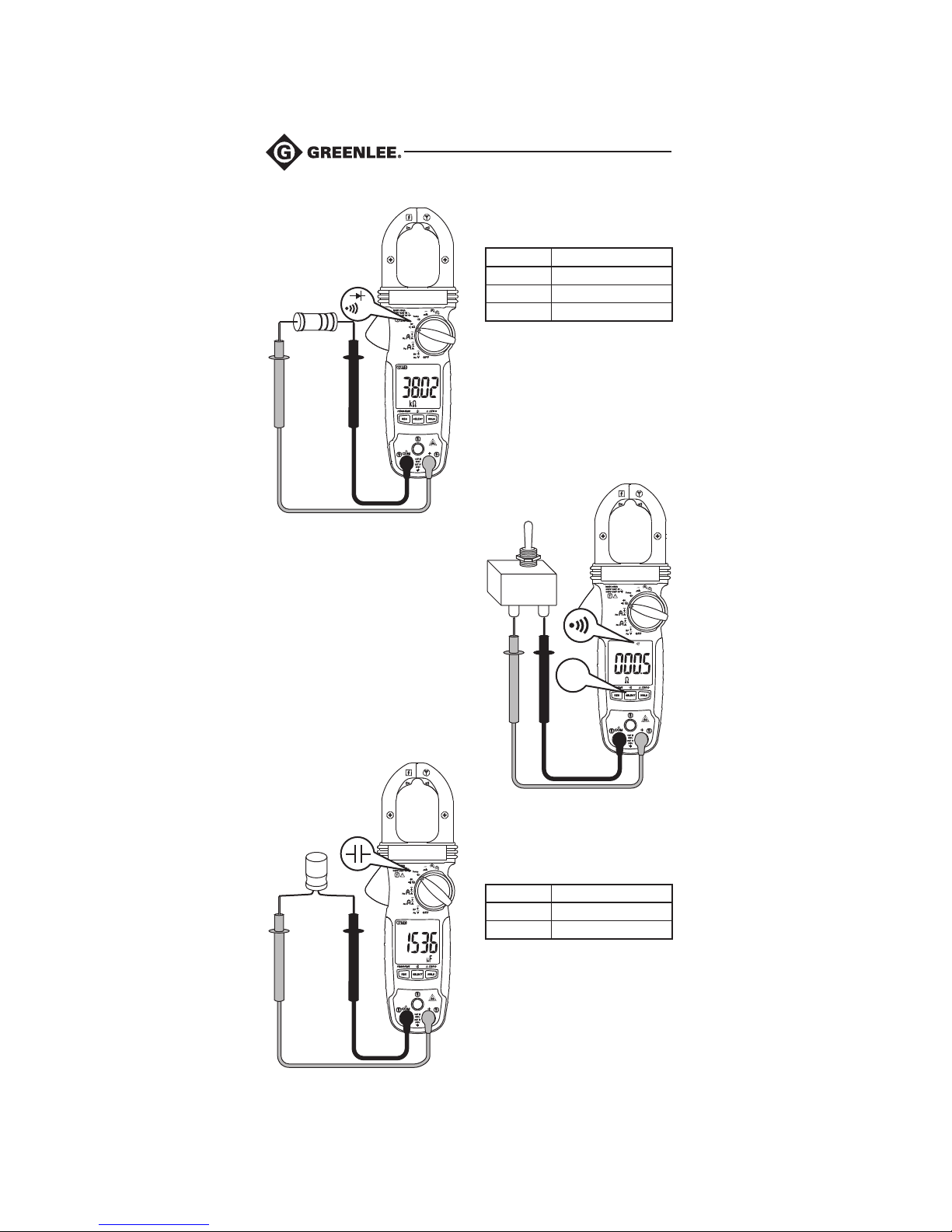
Resistance
Measurement
Ω
Continuity Check
Continuity
Tone Threshold: Between 10 Ω and 250 Ω
Response Time: Approximately 32 ms
Resistance
Range Accuracy
600.0 Ω ± (1.0% + 0.5 Ω)
6.000 kΩ ± (1.0% + 0.005 kΩ)
60.00 kΩ ± (1.0% + 0.05 kΩ)
Open Circuit Voltage: 1.0 VDC
SELECT
Capacitance
Measurement
Capacitance (CM-860, CM-960,
CMH-600, and CMI-600 only)
Range Accuracy*
200.0 μF ± (2.0% + 0.4 μF)
2500 μF ± (2.0% + 4 μF)
* For film capacitors (capacitors with
negligible dielectric absorption).
Note: For polarized capacitors, attach red
probe to positive terminal and black probe to
negative terminal of capacitor.
16
Find Quality Products Online at: [email protected]
www.GlobalTestSupply.com
Page 17
CM-660 • CM-860 • CM-960 • CMH-600 • CMI-600
Typical Measurements and Accuracy (cont’d)
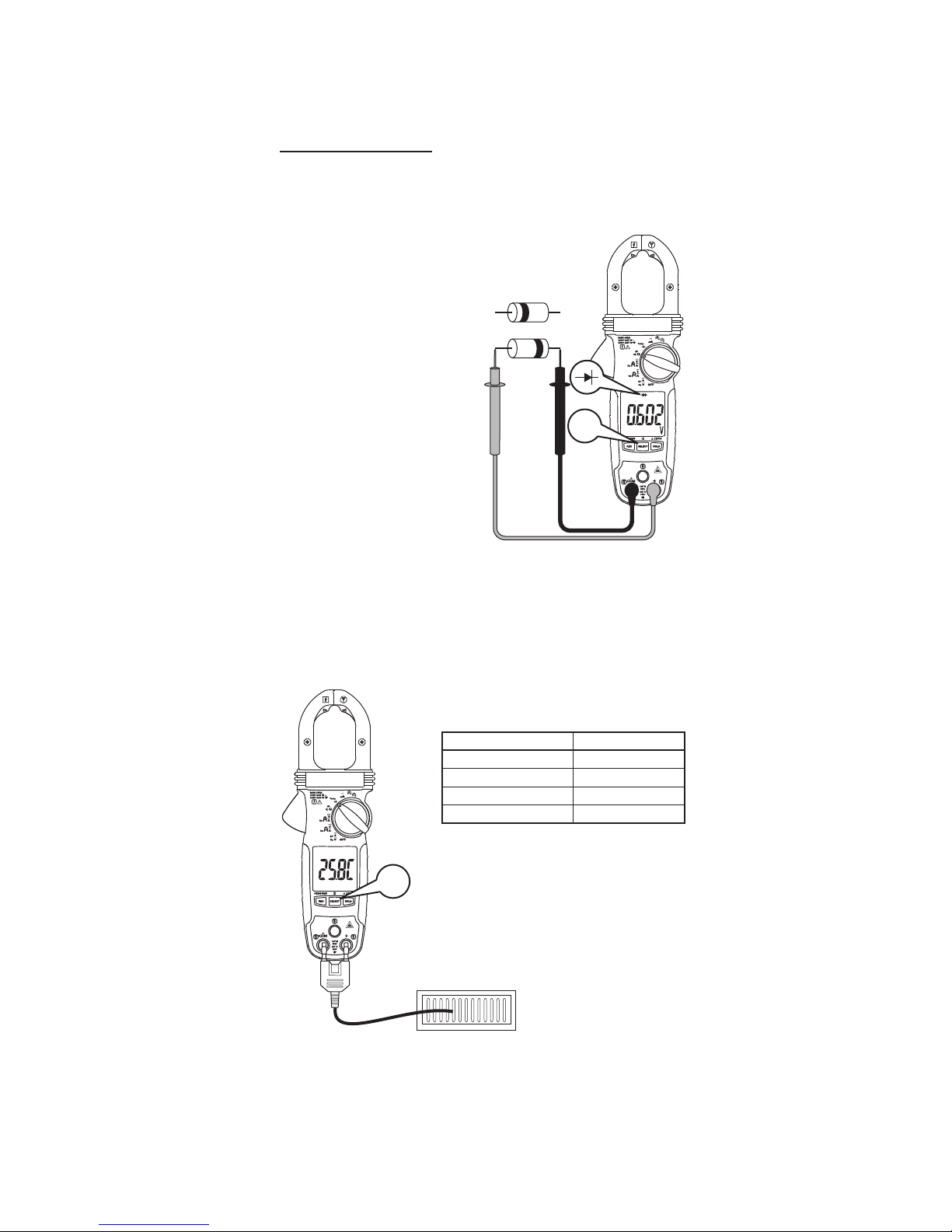
Diode Measurement
Reverse Bias
Forward Bias
Diode Test
Measuring Range: 2.000 V
Accuracy: ± (1.5% + 0.005 V)
Test Current (typical): 0.3 mA
Open Circuit Voltage (typical):
< 3.5 VDC
Temperature
SELECT
SELECT
Temperature (CMH-600 and CMI-600)
Range Accuracy*
-40.0 °C ~ 99.9 °C ± (1.0% + 0.8 °C)
100 °C ~ 400 °C ± (1.0% + 1 °C)
-40.0 °F ~ 211.8 °F ± (1.0% + 1.5 °F)
212 °F ~ 752 °F ± (1.0% + 2 °F)
* K-type thermocouple accuracy not included.
Thermocouple supplied with meter meets
standard JIS C 1602-1981.
17
Find Quality Products Online at: [email protected]
www.GlobalTestSupply.com
Page 18
Typical Measurements and Accuracy (cont’d)
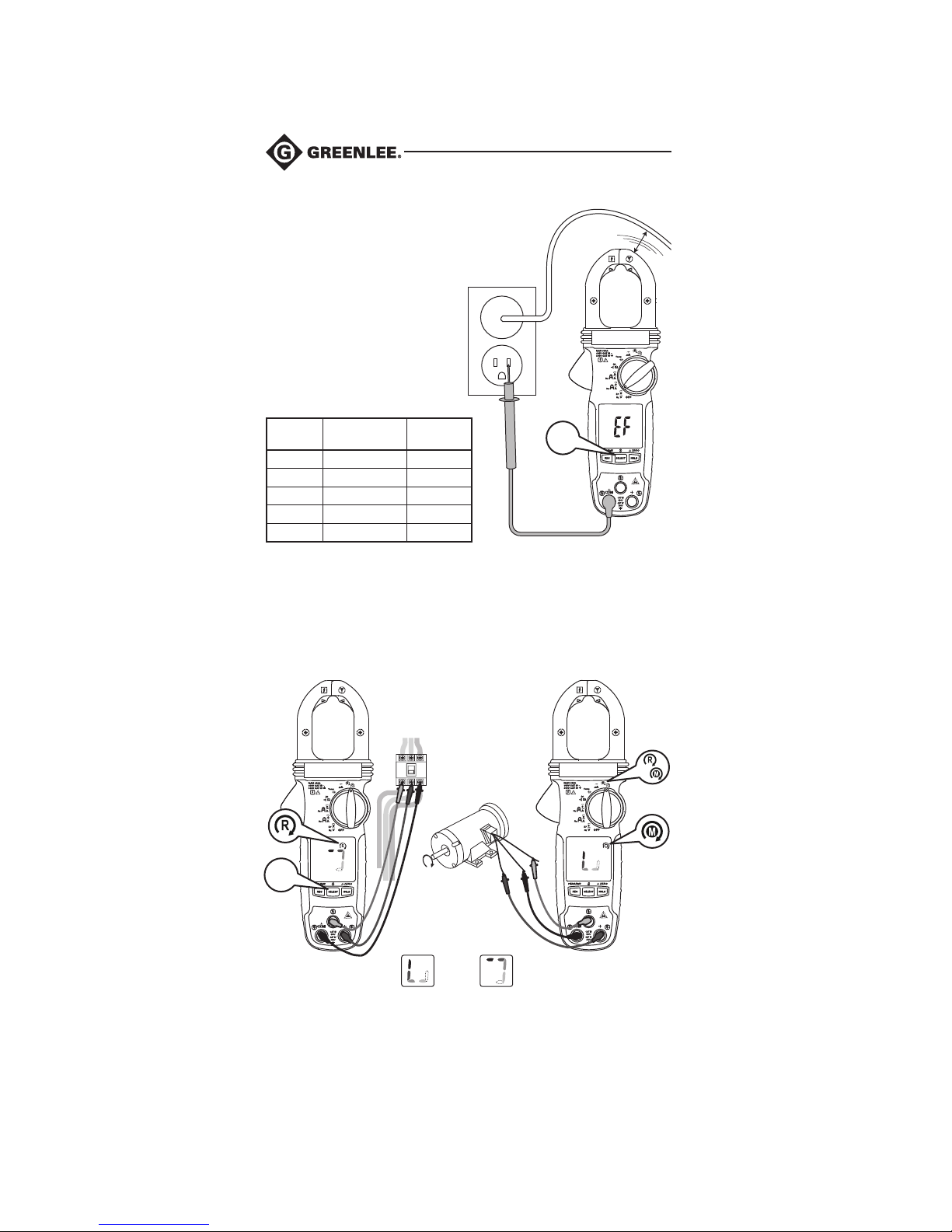
Electric Field
Note: CM-660
and CM-860
have a dedicated
switch position.
Non-contact EF Detection
Typical
Voltage
20 V 10 V ~ 36 V -
55 V 23 V ~ 83 V - 110 V 59 V ~ 165 V - - 220 V 124 V ~ 330 V - - - 440 V 250 V ~ 600 V - - - - -
Range at
50 Hz to 60 Hz
LCD
Indication
SELECT
B
A–Non-contact OR
B–Contact, precision measurement
10 mm
(0.4")
A
Phase Rotation Motor Rotation
SELECT
Clockwise Counterclockwise
18
Find Quality Products Online at: [email protected]
www.GlobalTestSupply.com
Page 19

CM-660 • CM-860 • CM-960 • CMH-600 • CMI-600
Specifications
Display: LCD, 3-5/6 digits 6000 counts
Polarity: Automatic
Update Rate: 5 per second nominal
Operating Conditions:
0 °C to 31 °C (32 °F to 88 °F), relative humidity 0% to 80%
31 °C to 40 °C (88 °F to 104 °F), relative humidity decreasing linearly
from 80% to 50%
Pollution Degree: 2
Indoor use only
Altitude: Operating below 2000 m (6500 ft)
Storage Temperature: -20 °C to 60 °C, relative humidity < 80%, with batteries removed
Temperature Coefficient: Nominal 0.15 x (Accuracy) per °C below 18 °C from 0 °C to
18 °C (32 °F to 64.4 °F) and above 28 °C from 28 °C to 40 °C (82.4 °F to 104 °F) or
otherwise specified
Sensing: True RMS
E.M.C.:
Meets EN61326-1:2006 (EN55022, EN61000-3-2, EN61000-3-3, EN61000-4-2,
EN61000-4-3, EN61000-4-4, , EN61000-4-5, EN61000-4-6, EN61000-4-8,
EN61000-4-11)
In an RF field of 1 V/m at a frequency of 405 MHz, DCA and DC+AC A mode
(CM-960 and CMI-960): Total Accuracy = Specified Accuracy + 20 digits
In an RF field of 1 V/m resistance mode (all models) and DC µA mode
(CMH-600 and CMI-600): Total Accuracy = Specified Accuracy + 25 digits
In an RF field of 3 V/m, all other modes and models not specified above:
Total Accuracy = Specified Accuracy + 20 digits
Safety: Double insulation per UL/IEC/EN61010-1 Ed. 3, IEC/EN61010-2-033 Ed. 1,
CAN/CSA C22.2 No. 61010-1 Ed. 3, IEC/EN61010-2-032 Ed. 2 and
IEC/EN61010-031 Ed. 1.1 to CAT III 600V and CAT IV 300V AC and DC
Overload Protections:
Jaws:
Current with Frequency Function: 600 A DC/AC RMS at ≤ 400 Hz
Terminals:
Voltage and Phase Rotation Function: 660 V DC/920 V AC RMS
All Other Modes and Functions: 600 V DC/AC RMS
Transient Protection: 6.0 kV (1.2/50 μs surge)
Power Supply: Two 1.5 V AAA batteries (NEDA 24A or IEC LR03)
Low Battery:
Capacitance and Frequency Function: Approximately 2.85 V
All Other Functions: Approximately 2.5 V
Current Consumption:
CM-960 and CMI-600: Typically 13 mA
CM-660, CM-860, and CMH-600: Typically 4.3 mA
APO Timing: Idle for 32 minutes
APO Consumption: 5 μA typical
Dimensions:
CM-960 and CMI-600: 222 mm x 76 mm x 37 mm (8.7" x 3.0" x 1.4")
CM-660, CM-860, and CMH-600: 217 mm x 76 mm x 37 mm (8.5" x 3.0" x 1.4")
Jaw Opening and Conductor Diameter: 30 mm max (1.18")
19
Find Quality Products Online at: [email protected]
www.GlobalTestSupply.com
Page 20

Measurement Categories
These definitions were derived from the international safety standard for insulation coordination as it applies to measurement, control, and laboratory equipment.
These measurement categories are explained in more detail by the International
Electrotechnical Commission; refer to either of their publications: IEC 61010-1 or
IEC60664.
Measurement Category II
Local level. Appliances, portable equipment, and the circuits they are plugged into.
Some examples include light fixtures, televisions, and long branch circuits.
Measurement Category III
Distribution level. Permanently installed machines and the circuits they are hard-wired
to. Some examples include conveyor systems and the main circuit breaker panels of a
building’s electrical system.
Measurement Category IV
Primary supply level. Overhead lines and other cable systems. Some examples include
cables, meters, transformers, and other exterior equipment owned by the power utility.
Statement of Conformity
Greenlee Textron Inc. is certified in accordance with ISO 9001 (2000) for our Quality
Management Systems.
The instrument enclosed has been checked and/or calibrated using equipment that is
traceable to the National Institute for Standards and Technology (NIST).
20
Find Quality Products Online at: [email protected]
www.GlobalTestSupply.com
Page 21
CM-660 • CM-860 • CM-960 • CMH-600 • CMI-600
Maintenance
Electric shock hazard:
Before opening the case, remove the test leads from the circuit and shut off the unit.
Failure to observe this warning could result in severe injury or death.
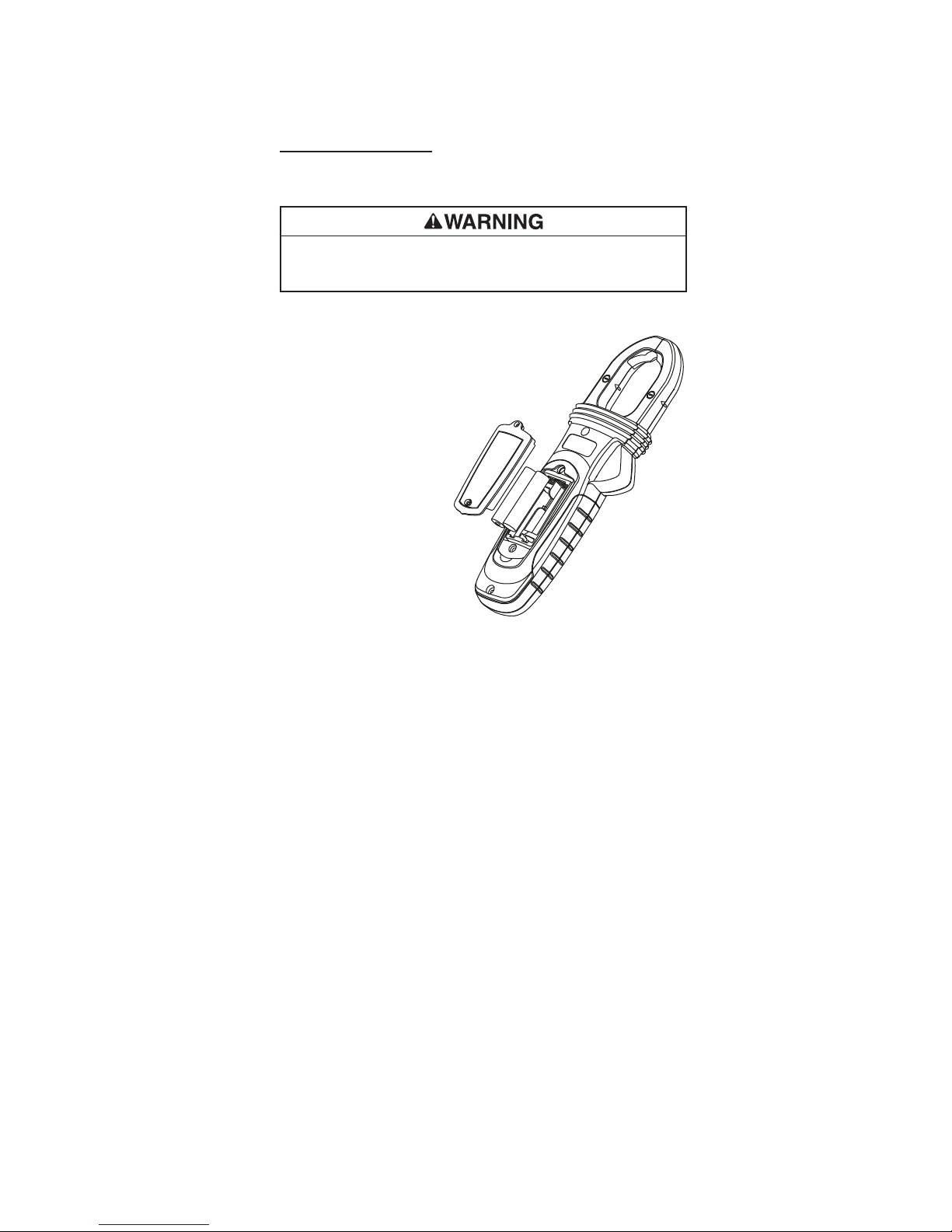
Replacing the Batteries
1. Disconnect the unit from the
circuit. Turn the unit OFF.
2. Remove the two screws from
the battery access door and
remove it.
3. Replace the batteries, making
sure to observe the polarity.
Cleaning and Storage
Periodically wipe the case with a
damp cloth and mild detergent; do
not use abrasives or solvents.
If the meter will not be used for
periods longer than 60 days,
remove the batteries and store
them separately.
21
Find Quality Products Online at: [email protected]
www.GlobalTestSupply.com
 Loading...