

Greenlee CCCX, CCCXC, GATOR PRO CCCX, GATOR PRO CCCXC, GATOR PRO CCCX11 Instruction Manual
...Page 1
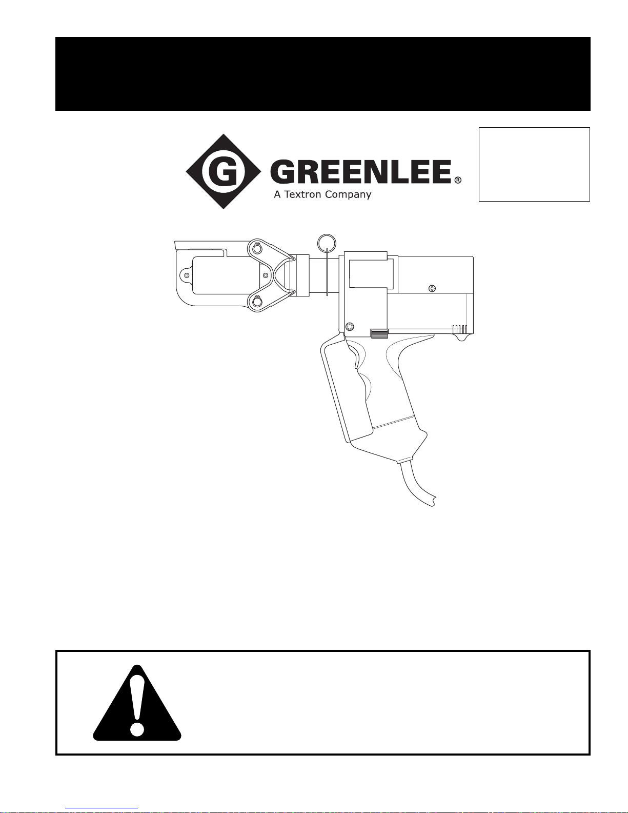
INSTRUCTION MANUAL
Serialnummer
GATOR™ PRO
CCCX and CCCXC Tools
120 Volt and 230 Volt
999 4509.6 © 2004 Greenlee Textron Inc. IM 1518 REV 4 6/04
Read and understand all of the instructions and
safety information in this manual before operating
or servicing this tool.
Page 2

CCCX and CCCXC Tools
Table of Contents
Description .....................................................................2
Safety ............................................................................. 2
Purpose of this Manual .................................................. 2
Important Safety Information...................................... 3–5
Identification ................................................................... 6
Specifications ................................................................. 6
Operation ................................................................. 7–15
Crimping .................................................................8–9
Cutting ......................................................................10
Punching.............................................................11–15
Available Adapters .......................................................16
Die Selection ................................................................ 17
Connector Selection..................................................... 17
Maintenance.................................................................18
Troubleshooting ........................................................... 18
Disassembly................................................................. 19
Assembly......................................................................20
Illustrations ............................................................. 21–23
Parts List ................................................................24–26
Description
The CCCX Tool is a hand-held, self-contained tool
intended to crimp cable, cut cable and threaded rod,
and punch holes with the proper adapters.
The CCCXC has a PVC-covered head.
Safety
Safety is essential in the use and maintenance of
Greenlee tools and equipment. This manual and any
markings on the tool provide information for avoiding
hazards and unsafe practices related to the use of this
tool. Observe all of the safety information provided.
Purpose of this Manual
This manual is intended to familiarize all personnel with
the safe operation and maintenance procedures for the
following Greenlee tools:
CCCX11 120 Volt Tool
CCCXC11 120 Volt Tool
with PVC-covered Head
CCCX22 230 Volt Tool
CCCXC22 230 Volt Tool
with PVC-covered Head
Keep this manual available to all personnel.
Replacement manuals are available upon request at no
charge.
All specifications are nominal and may change as design improvements occur. Greenlee Textron Inc. shall not be liable for damages
resulting from misapplication or misuse of its products.
GATOR and Kwik Stepper are registered trademarks of
Greenlee Textron Inc.
AVIA is a registered trademark of Avia International.
Blackburn is a registered trademark of Thomas & Betts.
Mobil is a registered trademark of Mobil Oil Corporation.
NUTO is a registered trademark of Exxon Corporation.
Tellus is a registered trademark of Shell Oil Company.
Greenlee / A Textron Company 2 4455 Boeing Dr. • Rockford, IL 61109-2988 USA • 815-397-7070
KEEP THIS MANUAL
Page 3
CCCX and CCCXC Tools
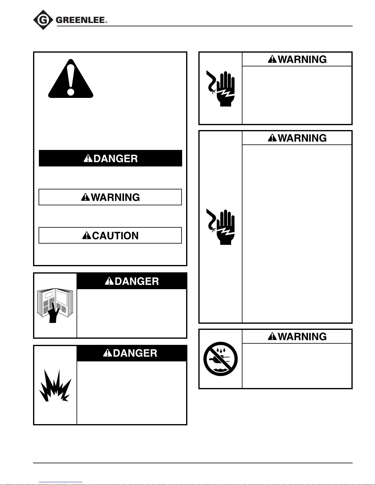
IMPORTANT SAFETY INFORMATION
SAFETY
ALERT
SYMBOL
This symbol is used to call your attention to hazards
or unsafe practices which could result in an injury or
property damage. The signal word, defined below,
indicates the severity of the hazard. The message
after the signal word provides information for
preventing or avoiding the hazard.
Immediate hazards which, if not avoided, WILL
result in severe injury or death.
Hazards which, if not avoided, COULD result in
severe injury or death.
Hazards or unsafe practices which, if not avoided,
MAY result in injury or property damage.
Read and understand all of the
instructions and safety information
in this manual before operating or
servicing this tool.
Failure to observe this warning will
result in severe injury or death.
Electric shock hazard:
This tool is not insulated. When
using this unit on or near energized
electrical lines, use proper personal
protective equipment.
Failure to observe this warning could
result in severe injury or death.
Electric shock hazard:
• Connect the power cord to a
receptacle of proper voltage for
the tool in use on a ground faultprotected circuit only.
• Do not modify the power cord or
plug.
• Inspect the power cord before use.
Repair or replace the cord if
damaged.
• Do not pull or carry by cord, use
the cord as a handle, close a door
on the cord, run over the cord, or
pull the cord around sharp edges
or corners. Keep the cord away
from heated surfaces.
• Do not unplug by pulling on the
cord. To unplug, grasp and pull
the plug—not the cord.
• Disconnect from power before
servicing.
Failure to observe these warnings
could result in severe injury or death.
Do not use this tool in a hazardous
environment. Hazards include
flammable liquids, gases, or other
materials. Using this tool in a
hazardous environment can result
in a fire or explosion.
Failure to observe this warning will
result in severe injury or death.
Greenlee / A Textron Company 3 4455 Boeing Dr. • Rockford, IL 61109-2988 USA • 815-397-7070
• Do not expose to rain.
• Do not use in wet or damp
locations.
Failure to observe these warnings
could result in severe injury or death.
Page 4
CCCX and CCCXC Tools
IMPORTANT SAFETY INFORMATION
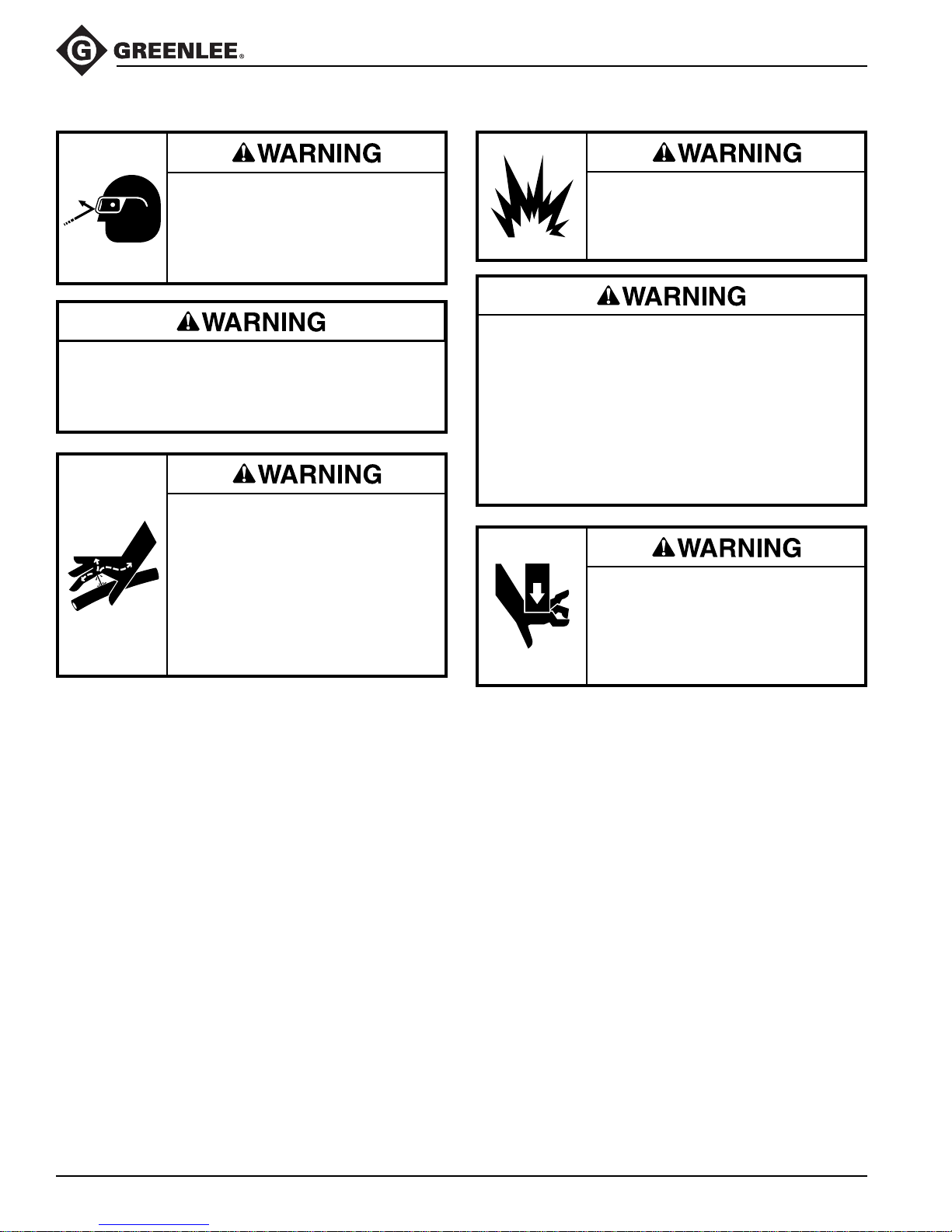
Wear eye protection when operating
or servicing this tool.
Failure to wear eye protection could
result in serious eye injury from
flying debris or hydraulic oil.
Do not operate the tool while wearing loose clothing.
Loose clothing can get caught in moving parts.
Failure to observe this warning could result in severe
injury or death.
Skin injection hazard:
Do not use hands to check for oil
leaks. Oil under pressure easily
punctures skin. If injured, seek
medical attention immediately to
remove oil.
Failure to observe this warning could
result in serious injury, gangrene, or
death.
Do not use solvents or flammable
cleaners to clean the tool body.
Solvents could ignite, causing
serious injury or property damage.
An incomplete crimp can cause a fire.
• Use proper die, connector, and cable combinations. Improper combinations can result in an
incomplete crimp.
• An audible “pop” indicates that the crimping tool
has achieved a complete crimp. If you do not
hear a “pop,” the crimp is incomplete.
Failure to observe these warnings could result in
severe injury or death.
Pinch points:
Keep hands away from the tool head
when in use.
Failure to observe this warning could
result in severe injury or death.
Greenlee / A Textron Company 4 4455 Boeing Dr. • Rockford, IL 61109-2988 USA • 815-397-7070
Page 5
CCCX and CCCXC Tools
IMPORTANT SAFETY INFORMATION
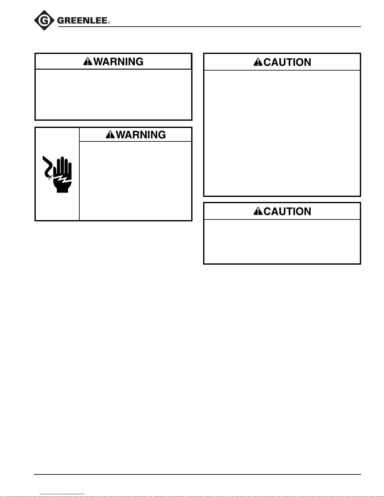
Inspect tool, dies, and adapters before use.
Replace any worn or damaged parts. A damaged or
improperly assembled tool can break and strike
nearby personnel.
Failure to observe this warning could result in severe
injury or death.
Extension cords:
• Use only 16, 14, or 12 AWG
extension cords.
• Do not use extension cords that
are longer than 30 m (100').
• Repair or replace damaged
extension cords.
Failure to observe these warnings
could result in severe injury or death.
• Do not operate tool without adapters. Damage
to the ram, tool head, or accessories may result.
• This tool is not designed for continuous use.
After 30 to 40 cycles, allow the tool to cool for
15 minutes.
• Do not place the tool in a vise. This tool is
designed for hand-held operation.
• Ensure that all bystanders are away from the
work area when operating the tool.
• Ensure that the work area is clean, dry,
uncluttered, and well-lit.
• Use this tool for the manufacturer’s intended
purpose only.
Failure to observe these precautions may result in
injury or property damage.
Do not perform any service or maintenance other
than as described in this manual. Injury or damage
to the tool may result.
Failure to observe this precaution may result in
injury and property damage.
Note: Keep all decals clean and legible, and replace
when necessary.
Greenlee / A Textron Company 5 4455 Boeing Dr. • Rockford, IL 61109-2988 USA • 815-397-7070
Page 6
IdentificationIdentification
CCCX and CCCXC Tools
6
5
7
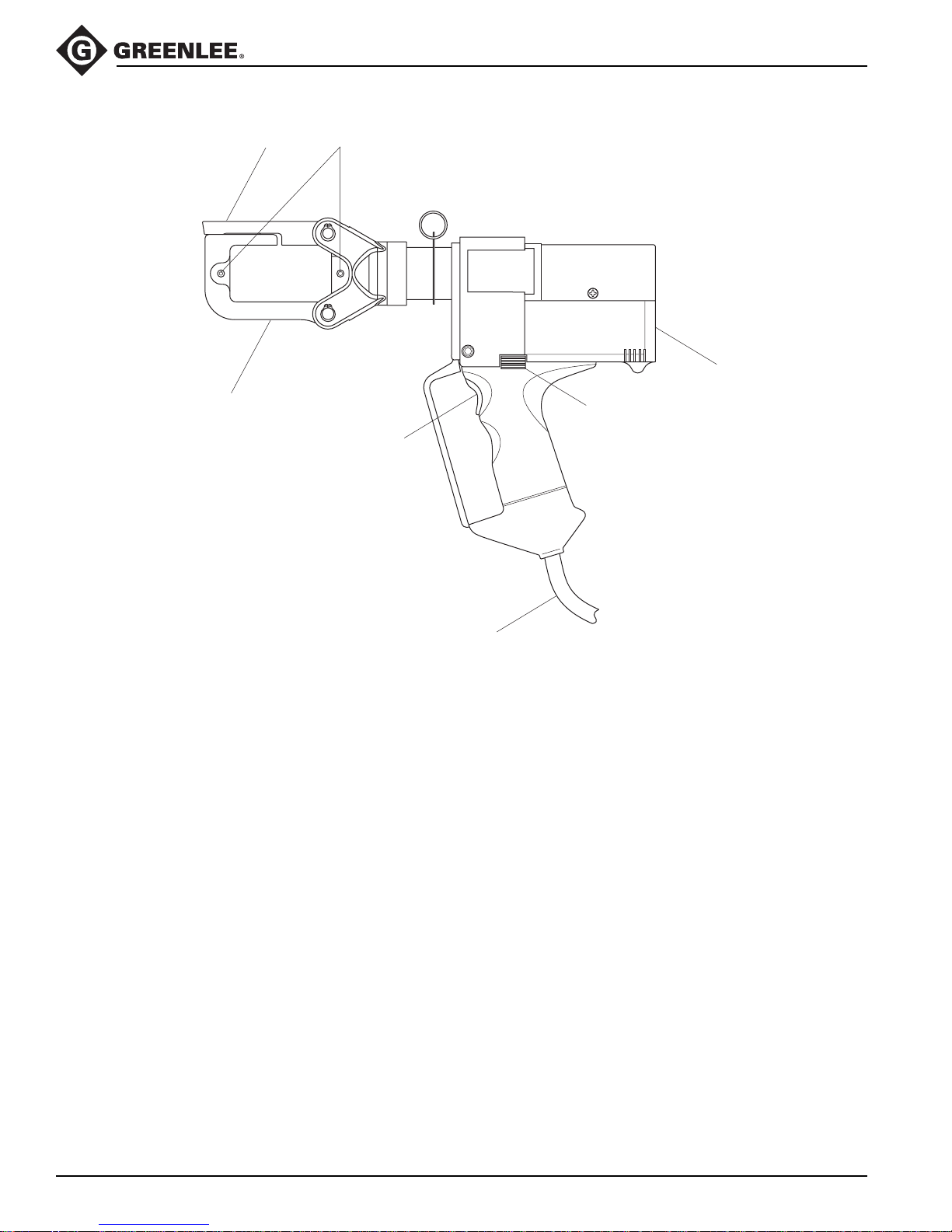
CCCX and CCCXC
1. Housing
2. Retract Button
3. Power Cord
4. Trigger
5. Head
6. Latch (for opening head)
7. Adapter Release Buttons
1
2
4
Specifications
Tool
Length...............................................................................................371 mm (14.6")
Width........................................................................................................76 mm (3")
Height ..................................................................................................279 mm (11")
Mass/Weight ..................................................................................... 4.02 kg (8.9 lb)
Sound Level...........................................................................< 75 dB (A) at 1 meter
Vibration.................................................................................................... < 2.5 m/s
Motor Voltage
Hydraulic Oil ....................................................50 ml (0.1 pint) of Shell Tellus® T 15
Crimping Tool
Maximum Crimping Cable Size ................... 600 kcmil copper; 350 kcmil aluminum
Crimping Time ..........................................................................................4 seconds
Cutting Tool
Maximum Cutting.................................... 40 mm (1-1/2") kcmil aluminum or copper
3
2
CCCX11 ............................................................................ 120 VAC, 60 Hz, 2.1 A
CCCX22 ............................................................................ 230 VAC, 50 Hz, 1.1 A
Greenlee / A Textron Company 6 4455 Boeing Dr. • Rockford, IL 61109-2988 USA • 815-397-7070
Page 7
Operation
CCCX and CCCXC Tools
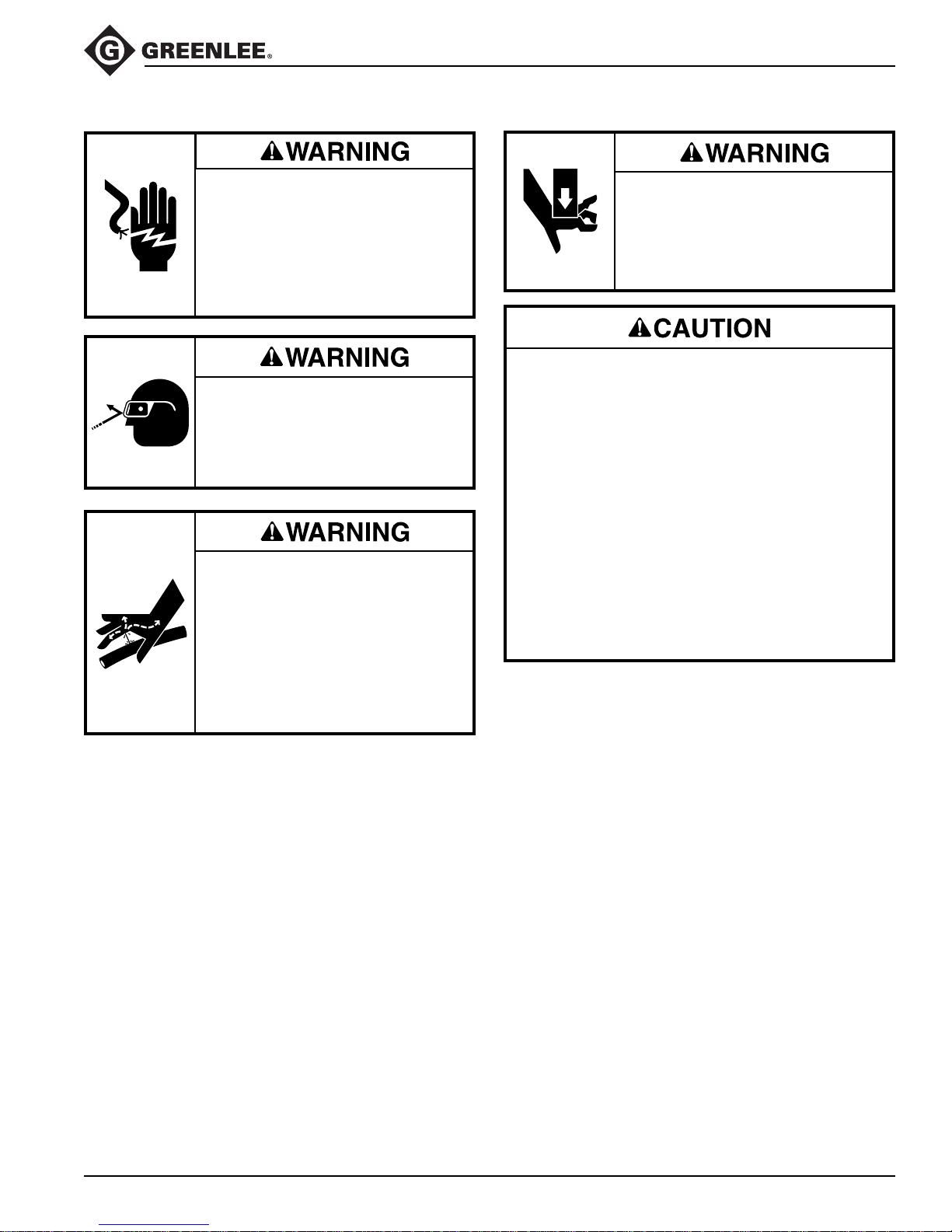
Electric shock hazard:
This tool is not insulated. When
using this unit on or near energized
electrical lines, use proper personal
protective equipment.
Failure to observe this warning could
result in severe injury or death.
Wear eye protection when operating
or servicing this tool.
Failure to wear eye protection could
result in serious eye injury from
flying debris or hydraulic oil.
Skin injection hazard:
Do not use hands to check for oil
leaks. Oil under pressure easily
punctures skin. If injured, seek
medical attention immediately to
remove oil.
Failure to observe this warning could
result in serious injury, gangrene, or
death.
Pinch points:
Keep hands away from the tool head
when in use.
Failure to observe this warning could
result in severe injury or death.
• Do not operate tool without adapters. Damage
to the ram, tool head, or accessories may result.
• This tool is not designed for continuous use.
After 30 to 40 cycles, allow the tool to cool for
15 minutes.
• Do not place the tool in a vise. This tool is
designed for hand-held operation.
• Ensure that all bystanders are away from the
work area when operating the tool.
• Ensure that the work area is clean, dry,
uncluttered, and well-lit.
• Use this tool for the manufacturer’s intended
purpose only.
Failure to observe these precautions may result in
injury or property damage.
Greenlee / A Textron Company 7 4455 Boeing Dr. • Rockford, IL 61109-2988 USA • 815-397-7070
Page 8
Operation (cont’d)
CCCX and CCCXC Tools
Crimping
Setup
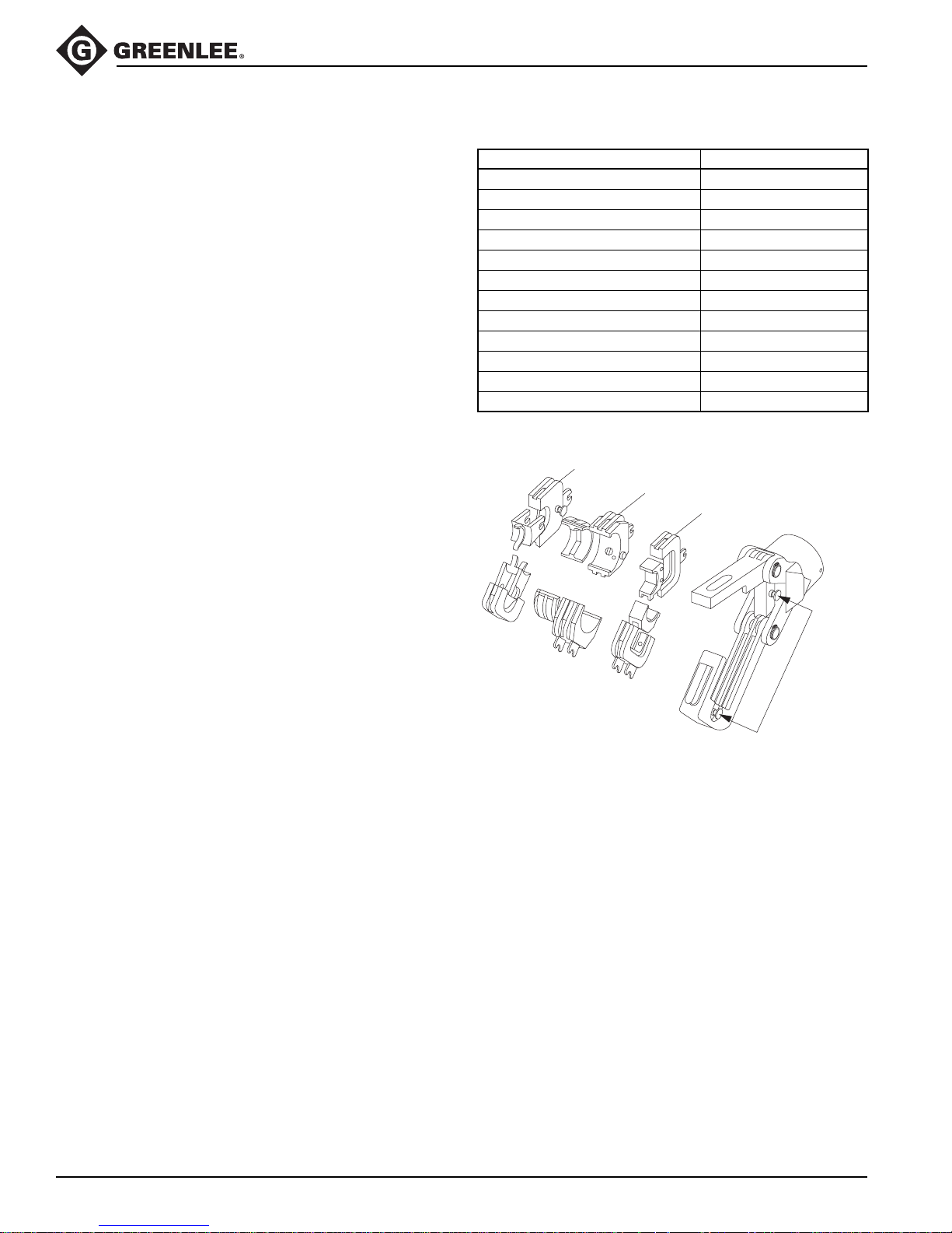
1. Open the tool head.
2. Remove any accessories from the tool head.
3. Select the appropriate set of dies. Use the
table provided on this page to select the
corresponding adapter set.
4. Install the adapters and dies—one set in each
groove. If either the adapters or dies have W-type
tabs, lock them in place with the W-type detents.
Important: W-type dies must be locked into place
or the die detents will be damaged.
5. Visually check the dies to ensure that they are
aligned correctly so that they will complete the
crimping operation.
6. Close the tool head.
Accessory Table
Dies Adapter Set
Greenlee K22, KA22, KC22-type UA22
Greenlee W-type UAW
Kearney “OD” UAK
Thomas & Betts “6TON” UAK
Profile UAW
D
3
Blackburn® “O” UAK
Huskie “HT” UAK
FCI Burndy “W” UAW
Huskie “HT-58” UAW
Ilsco “ND-60” UAW
Izumi “N58” UAW
Panduit “CD-2001” UAW
W-type
K22-type
Kearney
Important: W-type dies
must be locked into
place or the die detents
will be damaged.
Greenlee / A Textron Company 8 4455 Boeing Dr. • Rockford, IL 61109-2988 USA • 815-397-7070
W-type Detents: Press
and slide the adapter
and/or die into place.
Release to lock.
Page 9
Operation (cont’d)
Crimping (cont’d)
Crimping Procedure
Wear eye protection when operating
or servicing this tool.
Failure to wear eye protection could
result in serious eye injury from
flying debris or hydraulic oil.
An incomplete crimp can cause a fire.
• Use proper die, connector, and cable combinations. Improper combinations can result in an
incomplete crimp.
• An audible “pop” indicates that the crimping tool
has achieved a complete crimp. If you do not
hear a “pop,” the crimp is incomplete.
Failure to observe these warnings could result in
severe injury or death.
CCCX and CCCXC Tools
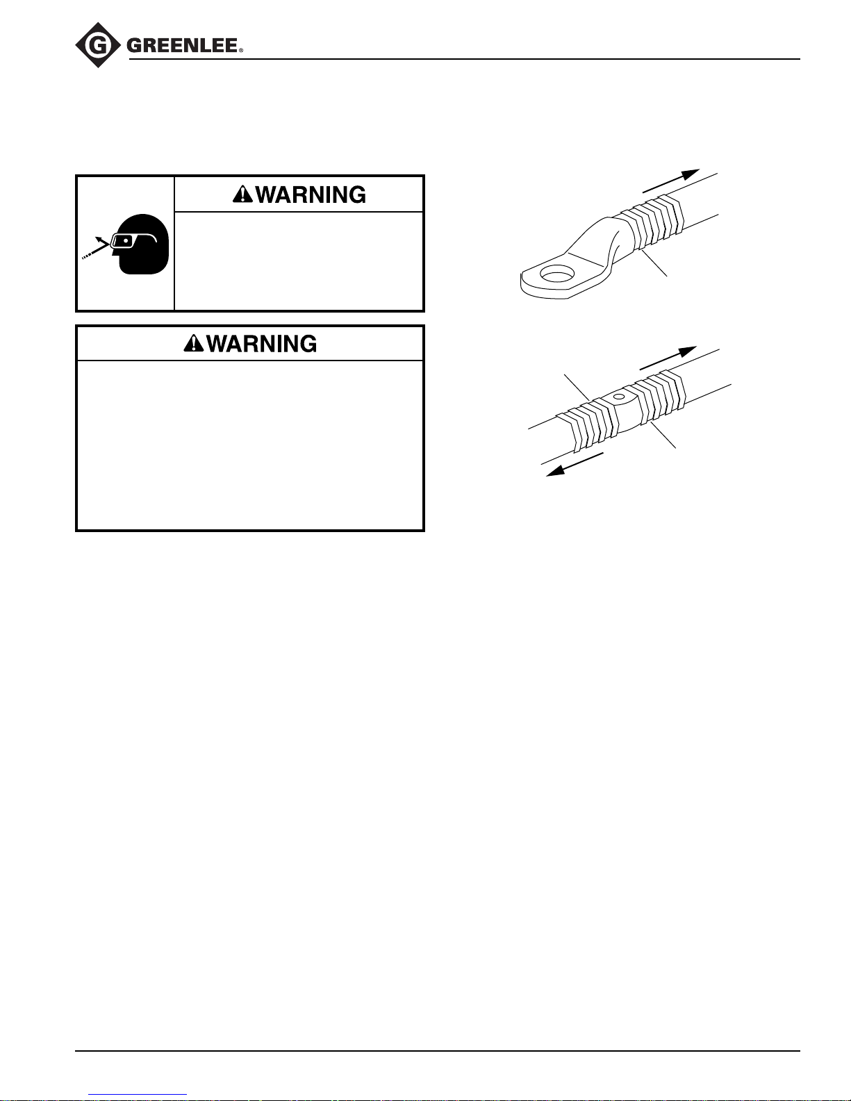
CRIMPING DIRECTION
1ST COMPRESSION
CRIMPING DIRECTION
SIDE B
1ST COMPRESSION
SIDE A
1ST COMPRESSION
SIDE B
CRIMPING DIRECTION
SIDE A
1. Press the latch and open the tool head.
2. Clean the die seat area.
3. Install the proper size and type of crimping dies.
4. Follow the connector manufacturer’s instructions
for appropriate cable strip length and surface
preparation.
5. Insert the properly assembled connector into the tool
head.
6. Close the tool head.
7. Using the sequence illustrated here, press the
trigger to advance the dies. Continue to crimp until
the pressure relief valve activates.
Note: Pressure relief occurs at approximately
60 kN (6.7 tons) and is indicated by an audible
“pop.”
8. After achieving pressure relief, the ram automatically
returns to the start position and the dies retract.
9. Complete the number of crimps specified by the
connector manufacturer.
10. Remove the connector from the crimping tool.
Note: After completing the last crimp on an aluminum
connector, wipe off the excess oxide inhibitor.
Greenlee / A Textron Company 9 4455 Boeing Dr. • Rockford, IL 61109-2988 USA • 815-397-7070
Page 10
Operation (cont’d)
CCCX and CCCXC Tools
Cutting
Electric shock hazard:
This tool is not insulated. When using
this unit as a cable cutter on or near
energized electrical lines, use proper
personal protective equipment.
Failure to observe this warning could
result in severe injury or death.
Wear eye protection when operating
or servicing this tool.
Failure to wear eye protection could
result in serious eye injury from
flying debris or hydraulic oil.
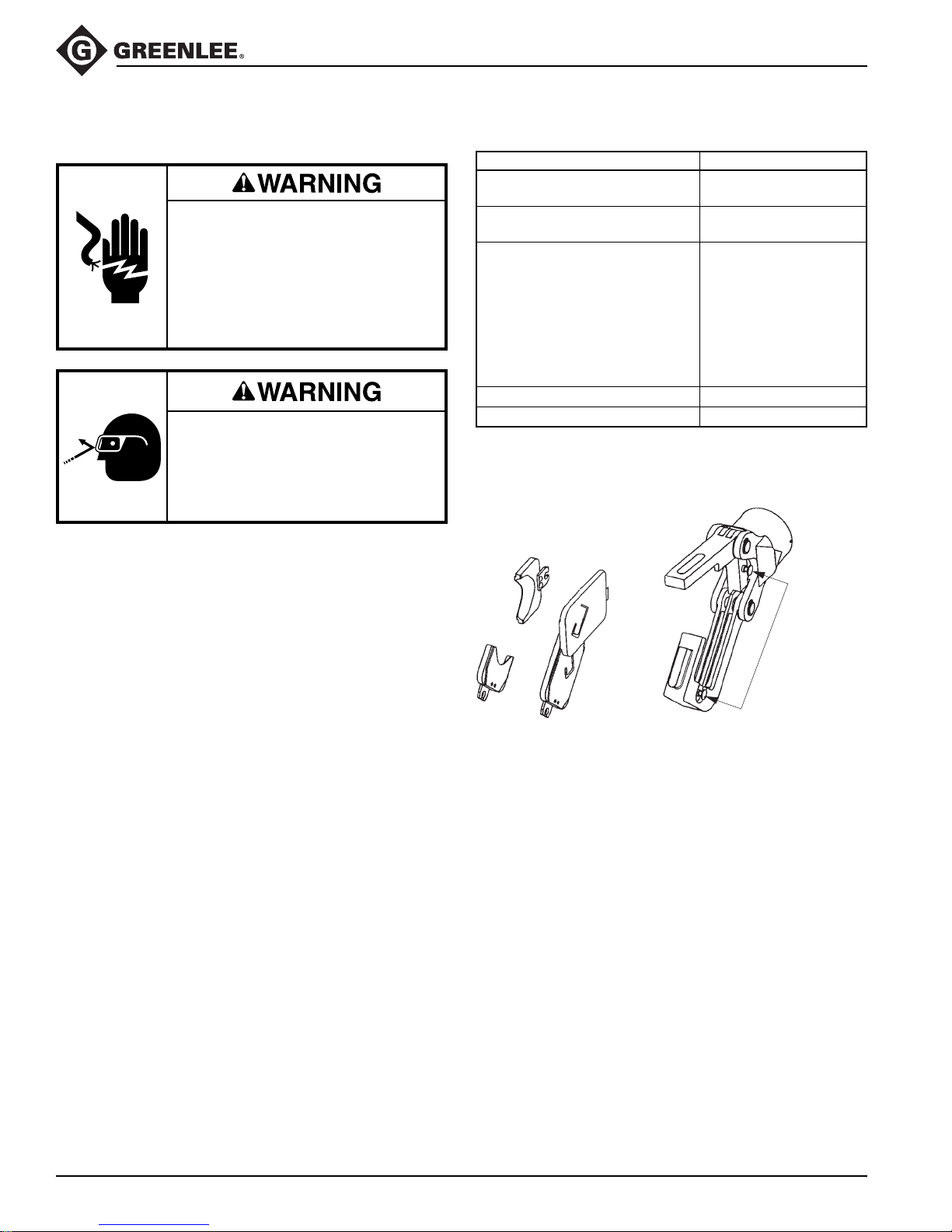
Setup
1. Open the tool head.
2. Remove any accessories from the tool head.
3. Select the appropriate set of blades, using the
table provided on this page.
4. Install one blade in each groove. If the blades have
W-type tabs, lock them in place with the W-type
detents.
Important: W-type dies must be locked into place
or the die detents will be damaged.
5. Visually check the blades to ensure that they are
aligned correctly so that they will complete the
butting operation.
6. Close the tool head.
Accessory Table
Task Blade
Copper and aluminum
26 mm (1.00") max.
Copper and aluminum
40 mm (1.56") max.
ACSR
Copperweld
ACAR
Guy strand
EHS guy strand UCACSR
Ground rod
Anchor rod
Soft bolts
Rebar
Threaded rod Threaded rod
DIN rail DIN rail
W-type Detents:
Press and slide the
adapter and/or die
into place.
Release to lock.
Important: W-type dies must be locked into
place or the die detents will be damaged.
UC26
UC40
Setup for Din Rail Cutters
1. Install both blades in the movable head.
2. Close the head.
3. Slide one blade over until it engages in the W-type
detents.
Greenlee / A Textron Company 10 4455 Boeing Dr. • Rockford, IL 61109-2988 USA • 815-397-7070
Cutting Procedure
1. Press the latch and open the tool head.
2. Position the item to be cut in the tool head.
3. Close the tool head.
4. Pull the trigger to cut the item.
5. Release the trigger when the cut is complete.
6. The ram returns automatically.
Page 11
Operation (cont’d)
Punching
CCCX and CCCXC Tools
Electric shock hazard:
Do not use this tool as a punch
driver on or near live circuits. This
includes, but is not limited to, the
following circumstances:
• Energized electrical lines
• Energized circuit breaker panels
and fuse boxes
• Junction boxes with energized
circuits
Failure to observe this warning could
result in severe injury or death.
Wear eye protection when operating
or servicing this tool.
Failure to wear eye protection could
result in serious eye injury from
flying debris or hydraulic oil.
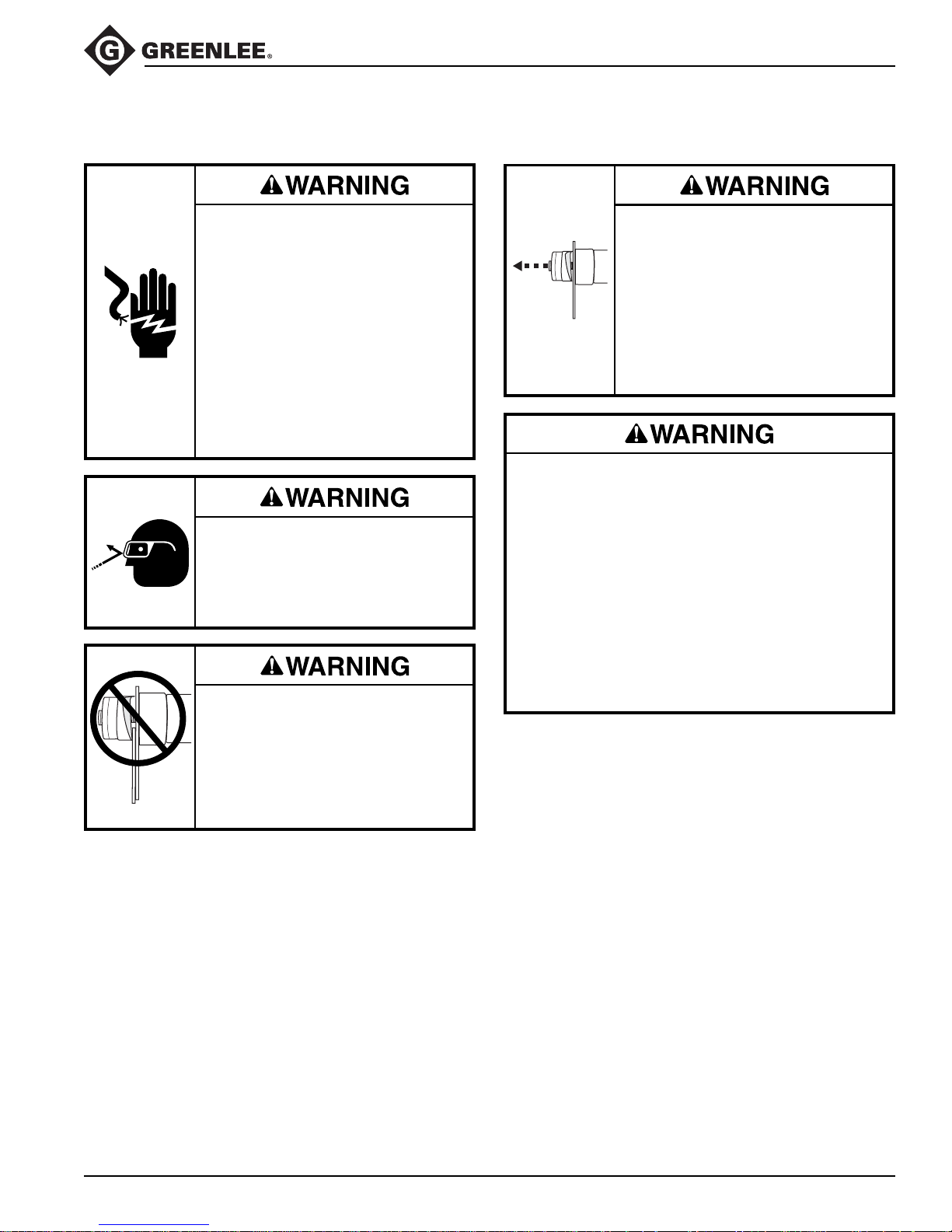
Do not attempt to punch a hole
through two or more thicknesses of
material. This will bend or break the
draw stud, and could throw parts
with great force.
Failure to observe this warning could
result in severe injury or death.
A component failure could throw
broken parts.
• Do not allow anyone to stand in
front of the punch.
• Close access doors or covers on
any equipment that is in line with
the punch.
Failure to observe this warning could
result in severe injury or death.
Set up the tool properly. An improper setup could
cause a component to fail and strike nearby
personnel with great force.
• Thread the punch completely onto the draw stud.
All of the punch threads must be engaged by the
draw stud threads. Incomplete assembly could
cause a component failure.
• Use only Greenlee punches, dies, and draw
studs. Other manufacturers’ components might
not withstand the forces generated by this punch
driver.
Failure to observe these warnings could result in
severe injury or death.
Greenlee / A Textron Company 11 4455 Boeing Dr. • Rockford, IL 61109-2988 USA • 815-397-7070
Page 12
Operation (cont’d)
CCCX and CCCXC Tools
Punching (cont’d)
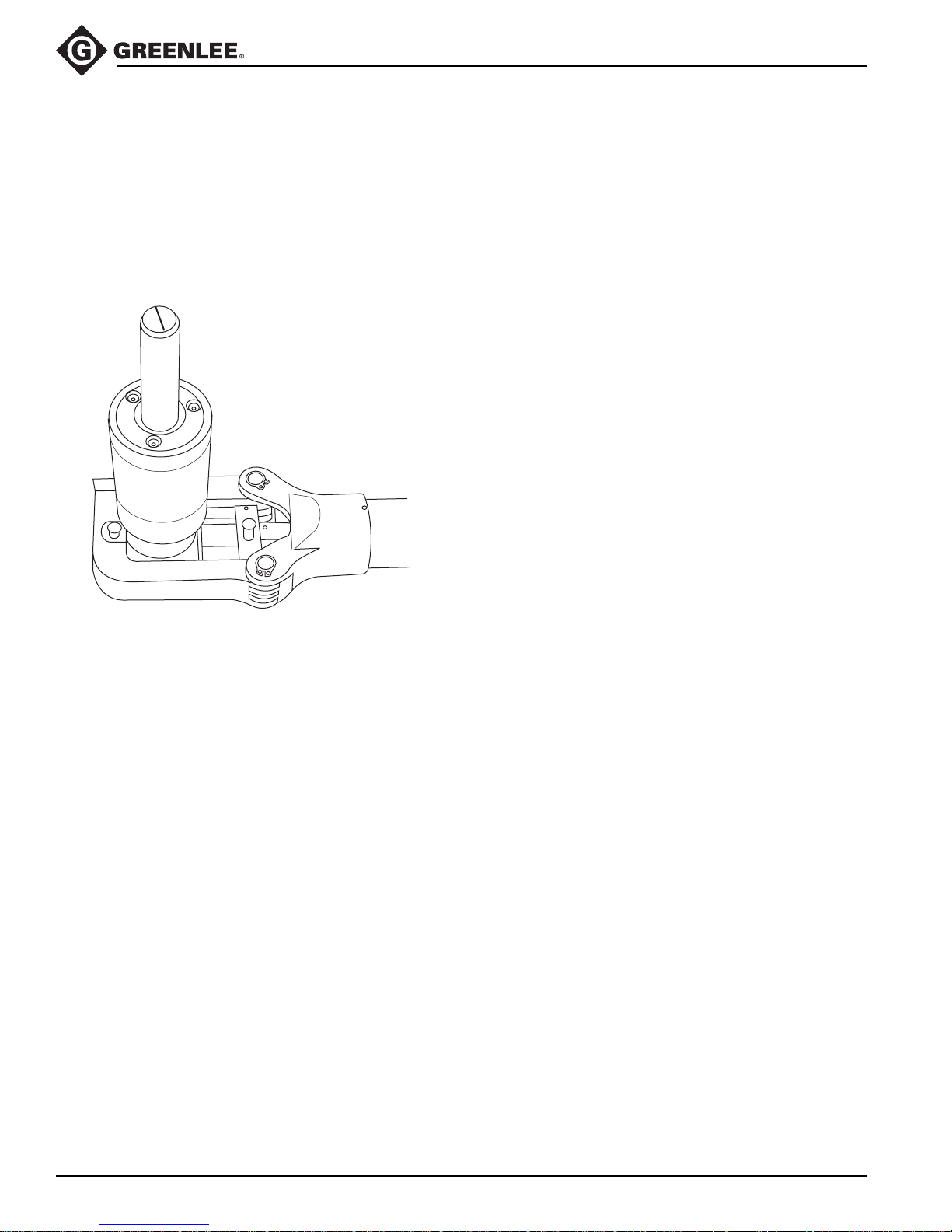
Setup and Punching Procedure
1. Open the tool head.
2. Remove any accessories from the tool head.
3. Install the punch driver so that the drive piston is
toward the yoke, as shown.
4. Close the tool head.
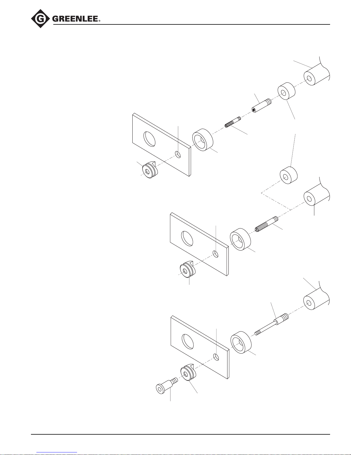
5. Select the punch, die, and draw stud to make the
appropriate size hole. Refer to the illustrations on the
following pages.
6. Determine and mark the exact location for the hole.
Use a Greenlee Kwik Stepper® drill bit to drill a hole
that is slightly larger than the draw stud. This is the
pilot hole.
7. Push the retract button and hold the button until the
ram is completely retracted.
8. Thread the 3/4" draw stud or 3/4" adapter completely
into the punch driver. Refer to the illustrations on the
following pages.
Note: For a punch and die with a 3/8" center hole,
thread the 3/8" draw stud into the end of the 3/4"
adapter.
9. Install a spacer, if necessary. Refer to the illustrations on the following pages.
10. Slide the die over the draw stud with the open end of
the die facing away from the punch driver.
11. Insert the draw stud through the pilot hole.
12. Thread the punch onto the draw stud with the cutting
surfaces of the punch facing the material. Tighten
the punch by hand until the spacer, die, material,
and punch contact each other.
Note: All of the punch threads must be engaged by
the draw stud threads. If any of the punch threads
are not engaged, disassemble the setup, remove the
spacer, and reassemble the setup.
Note: A “popping” sound indicates that the tool has
reached relief pressure. This may indicate that the
attempted operation is beyond the capacity of the
tool.
13. Pull the trigger.
14. Release the trigger when the punch completes the
hole. The ram returns automatically.
15. Unscrew the punch. Remove slugs from the die.
Remove the spacer and unscrew the draw stud.
Greenlee / A Textron Company 12 4455 Boeing Dr. • Rockford, IL 61109-2988 USA • 815-397-7070
Page 13
Operation (cont’d)
CCCX and CCCXC Tools
Punching (cont’d)
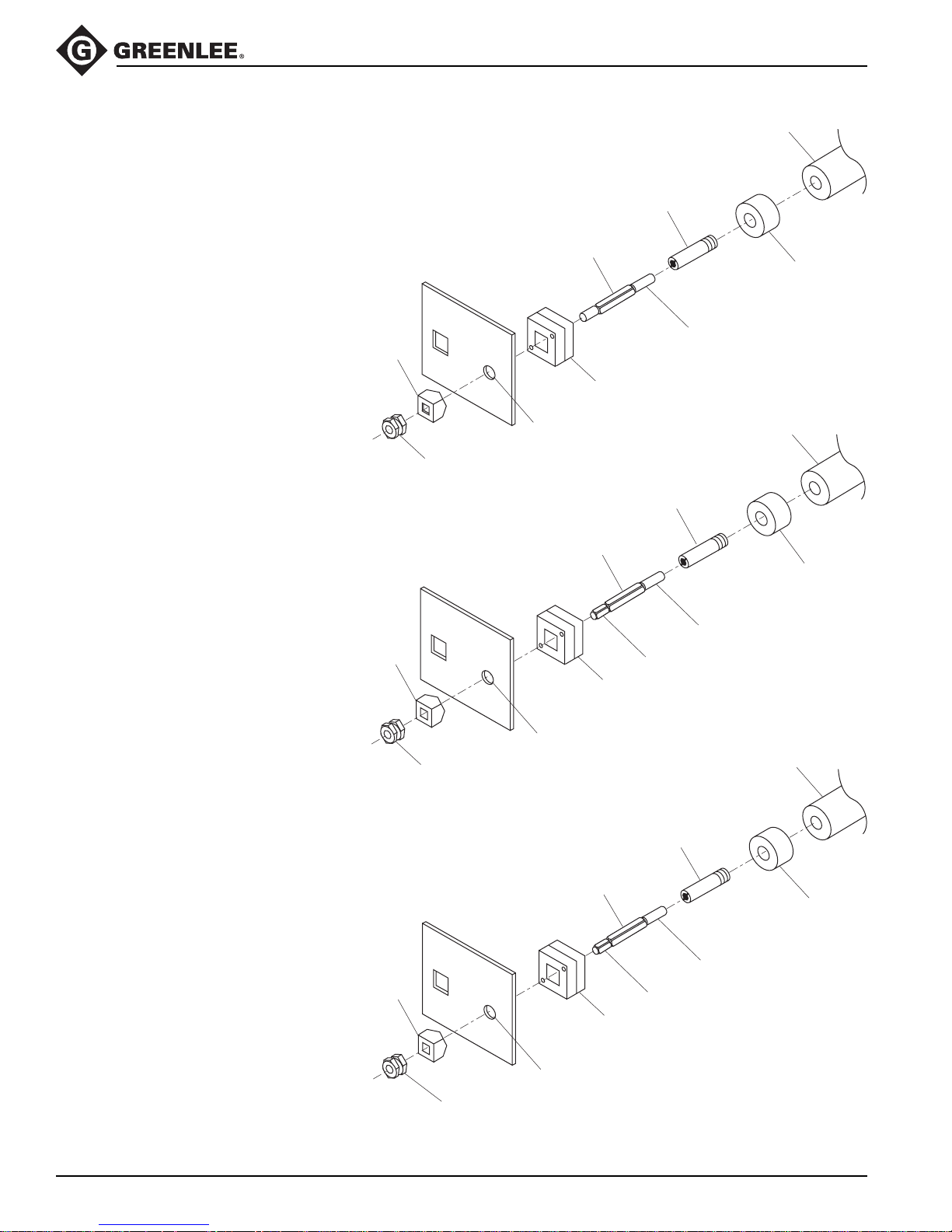
Round Punches
Metric: 22.5 mm (max.)
Conduit Size: 1/2" (max.)
Actual Size: 0.885" (max.)
Round Punches
Metric: 28.3 mm to 61.5 mm
Conduit Size: 3/4" to 2"
Actual Size: 1.115" to 2.416"
Punch
1/2" (12.7 mm)
Pilot Hole
Die
7/8" (22.2 mm)
Pilot Hole
UA6P
Punch Driver
33967
3/4" Adapter
03248
Spacer
30043
3/8" Draw Stud
UA6P
Punch Driver
3/4"
Draw Stud
31874
7/16" to 3/4"
Adapter
(optional)
Punch
1/2" (12.7 mm)
Pilot Hole
Punch—1-1/4"
(ø 1.701" [43.2 mm])
Conduit
Maximum Size
Die
UA6P
Punch Driver
29451
7/16" Draw Stud
(optional)
Die
Greenlee / A Textron Company 13 4455 Boeing Dr. • Rockford, IL 61109-2988 USA • 815-397-7070
Page 14
CCCX and CCCXC Tools
Operation (cont’d)
Punching (cont’d)
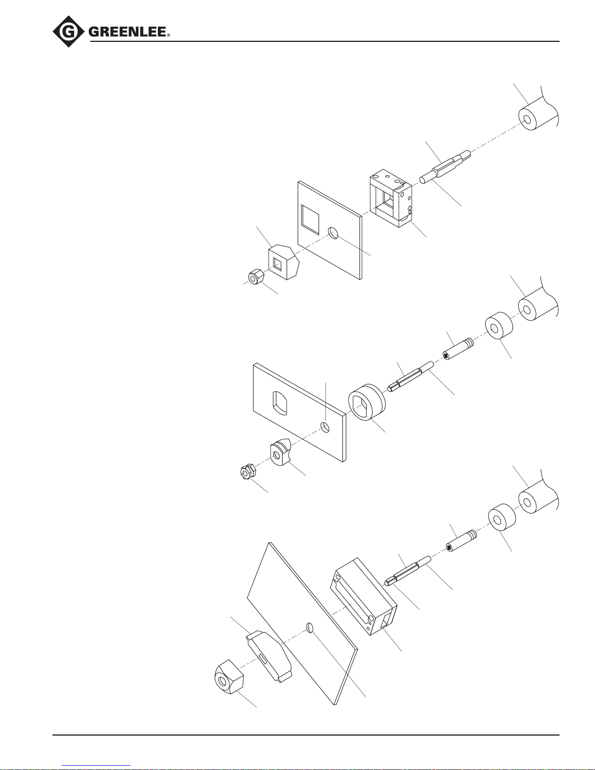
Square and Rectangular Punches
Metric: 12.7 mm square
Inches: 1/2" square
Metric: 11.1 mm x 22.2 mm rectangular
Inches: 7/16" x 7/8" rectangular
Punch
05244
1/4" Counter Nut
1/4" Draw Stud
Pilot Hole
3/8" Draw Stud
UA6P
Punch Driver
60114
1/4" Adapter
60115
03248
Spacer
End with Long Threads
Die
UA6P
Punch Driver
33967
3/8" Adapter
60116
Square and Rectangular Punches
Metric: 15.9 mm to 24.0 mm square
Inches: 5/8" to 0.945" square
Metric: 17.0 mm x 19.0 mm rectangular
Inches: 0.670" x 0.749" rectangular
Square and Rectangular Punches
Metric: 25.4 mm square
Inches: 1" square
Metric: 19.1 mm x 29.0 mm to
31.8 mm x 35.1 mm rectangular
Inches: 0.750" x 1.140" to
1.250" x 1.380" rectangular
Punch
04638
3/8" Counter Nut
Punch
Pilot Hole
3/8" Draw Stud
Pilot Hole
03248
Spacer
End with Long Threads
Threads with Flats
Die
UA6P
Punch Driver
60167
1/2" Adapter
60117
03248
Spacer
End with Long Threads
Threads with Flats
Die
Greenlee / A Textron Company 14 4455 Boeing Dr. • Rockford, IL 61109-2988 USA • 815-397-7070
60258
1/2" Counter Nut
Page 15
CCCX and CCCXC Tools
Operation (cont’d)
Punching (cont’d)
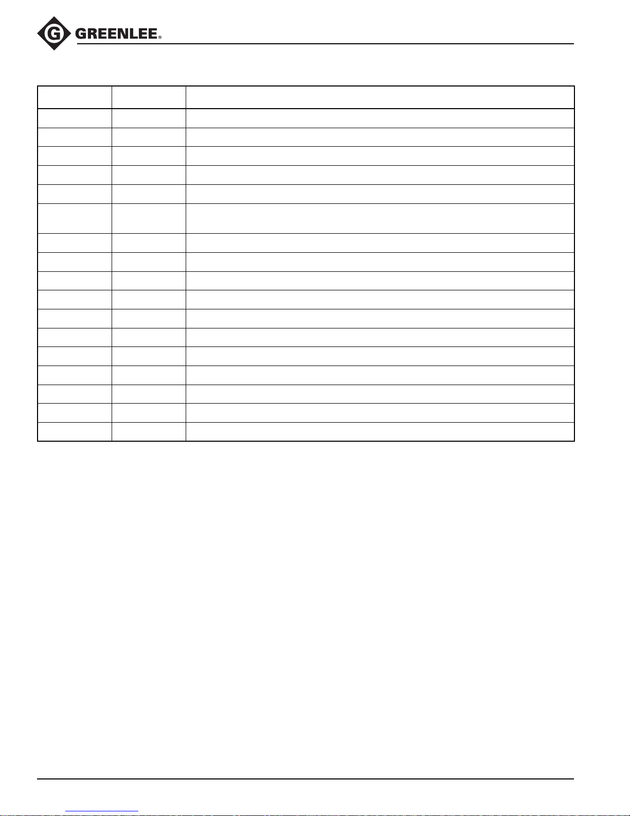
Square and Rectangular Punches
Metric: 46.0 mm to 68.0 square
Inches: 1.811" to 2.677" square
Metric: 33.3 mm x 66.7 mm to
35.0 mm x 65.0 mm rectangular
Inches: 1.312" x 2.625" to
1.378" x 2.559" rectangular
Punch
3/4" Counter Nut
60235
3/4" Draw Stud
Pilot Hole
UA6P
Punch Driver
60118
End with Long Threads
Die
UA6P
Punch Driver
Adapter
“D”, Double “D”, and
Key Punches
Electronic Connector
Panel Punches
Punch
Counter Nut
Punch
Pilot Hole
Draw Stud
03248
Spacer
End with Long Threads
Die
UA6P
Punch Driver
33967
3/8" Adapter
34421
3/8" Draw Stud
03248
Spacer
End with Long Threads
Threads with Flats
Greenlee / A Textron Company 15 4455 Boeing Dr. • Rockford, IL 61109-2988 USA • 815-397-7070
04638
3/8" Counter Nut
Die
7/16" (11.1mm)
Pilot Hole
Page 16
Available Adapters
CCCX and CCCXC Tools
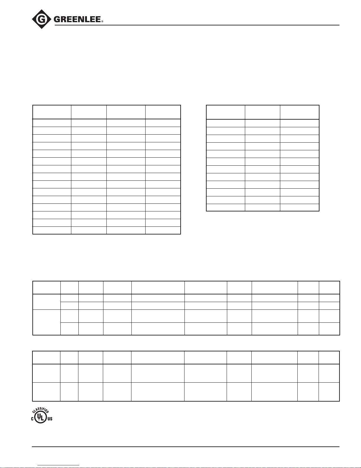
Adapter
UA22 500 7062.2 Adapter for Greenlee 22-Series dies
UAK 500 7033.9 Adapter for Kearney and T&B dies
UAW 500 7035.5 Adapter for W-type dies, D
UC26 500 6714.1 Cutter blades for copper and aluminum 26 mm (1") max.
UC40 500 7036.3 Cutter blades for copper and aluminum 40 mm (1-1/2") max.
UCACSR 500 7037.1 Cutter blades for ACSR, ACAR, standard guy wire, EHS guy wire, copperweld,
UCUNC14 500 7038.0 Cutter blades for 1/4" threaded rod
UCUNC38 500 7039.8 Cutter blades for 3/8" threaded rod
UCUNC12 500 7274.9 Cutter blades for 1/2" threaded rod
UCM5 500 7053.3 Cutter blades for M5 threaded rod
UCM6 500 7050.9 Cutter blades for M6 threaded rod
UCM8 500 7051.7 Cutter blades for M8 threaded rod
UCM10 500 7052.5 Cutter blades for M10 threaded rod
UCD3575 500 7041.0 DIN rail cutter blades—35 x 7.5
Greenlee
Part No.
Description
3
ground rod, anchor rod, soft bolts, rebar
UCD3215 500 7042.8 DIN rail cutter blades—32 x 15
UCD3515 500 7043.6 DIN rail cutter blades—35 x 15
UA6P 500 7020.7 Punch driver adapter
Greenlee / A Textron Company 16 4455 Boeing Dr. • Rockford, IL 61109-2988 USA • 815-397-7070
Page 17
CCCX and CCCXC Tools
Die Selection
Crimps made on copper cable with Greenlee KC22-type dies and the copper connectors listed here are
cUL and UL classified and CSA certified.
Crimps made on copper or aluminum cable with Greenlee KA22-type dies and the dual-rated aluminum connectors
listed here are cUL and UL classified.
Refer to “Connector Selection” for brand names and model numbers of appropriate lugs as well as crimping instructions.
W-type or X-type dies can be used to crimp 8 AWG to 500 kcmil copper and 8 AWG to 4/0 AWG aluminum.
Dies for Copper Connectors Dies for Dual-rated Aluminum Connectors
Catalog UPC Cable Color
Number Number Size Code
KC22-8 03079 8 AWG Red
KC22-6 03080 6 AWG Blue
KC22-4 03081 4 AWG Gray
KC22-2 03082 2 AWG Brown
KC22-1 03083 1 AWG Green
KC22-1/0 03084 1/0 AWG Pink
KC22-2/0 03085 2/0 AWG Black
KC22-3/0 03086 3/0 AWG Orange
KC22-4/0 03087 4/0 AWG Purple
KC22-250 03088 250 kcmil Yellow
KC22-300 03089 300 kcmil White
KC22-350 03090 350 kcmil Red
KC22-400 03091 400 kcmil Blue
KC22-500 03092 500 kcmil Brown
KC22-600 03093 600 kcmil Green
Catalog UPC Cable
Number Number Size
KA22-8 06744 8 AWG
KA22-6 06745 6 AWG
KA22-4 06746 4 AWG
KA22-2 06747 2 AWG
KA22-1 06749 1 AWG
KA22-1/0 06750 1/0 AWG
KA22-2/0 06751 2/0 AWG
KA22-3/0 06752 3/0 AWG
KA22-4/0 06753 4/0 AWG
KA22-250 06754 250 kcmil
KA22-300 06755 300 kcmil
KA22-350 06756 350 kcmil
Connector Selection
Tool Range: Copper — 8 AWG to 600 kcmil; Dual-rated Aluminum — 8 AWG to 350 kcmil
When used with KC22-type dies, this tool is cUL and UL classified for use with the following connector brands:
Connector Barrel
Type Type Union Crimps*
Copper
Splice
Copper
Lugs
Anderson Blackburn
Short VHSS CSP YS-L CT SCSS/SCS 54504–54520 BCU A
Long VHS CU YS CTL SCL/SCH 54804–54820 BBCU B
Short VHCS CTL-2/CTL
Long VHCL CTL-L/LCN YA-2N
®
FCI Burndy Ilsco Panduit T&B
YA-2LN/YA-L/YA-2L
YA/YA-L-TC/YA-L-2TC LCD 54204–54218
CRA/CRB
CRA-L/CRB-L
CRA-2L/CRB-2L 54850BE–54878BE
LCAS/LCA 54104–54120
LCB/LCC
54930BE–54920BE
When used with KA22-type dies, this tool is cUL and UL classified for use with the following connector brands:
Connector Barrel
Type Type Union Crimps*
Dual-rated
Aluminum — VACS ASP YS-A AS SA 60501–60565 PIK C
Splice **
Dual-rated
Aluminum — VACL ATL BLUA C
Lugs
* Use the number of crimps listed in the last column instead of the number provided with the connector:
95R7
A — 8 to 1/0 AWG: 1 crimp
** 6 AWG to 350 kcmil
Anderson Blackburn
2/0 AWG to 600 kcmil: 2 crimps
®
FCI Burndy Ilsco Panduit T&B
YA-A ACL/ACN LAA/LAB 60101–60166
YA-ATN 2ACL/2ACN ** 60230–60267
B — 8 to 1/0 AWG: 2 crimps
2/0 to 3/0 AWG: 3 crimps
4/0 AWG to 600 kcmil: 4 crimps
C — 8 to 2 AWG: 2 crimps
1 to 3/0 AWG: 3 crimps
4/0 AWG to 350 kcmil: 4 crimps
Penn- No. of
BLU A
BBLU B
Penn- No. of
Greenlee / A Textron Company 17 4455 Boeing Dr. • Rockford, IL 61109-2988 USA • 815-397-7070
Page 18
Maintenance
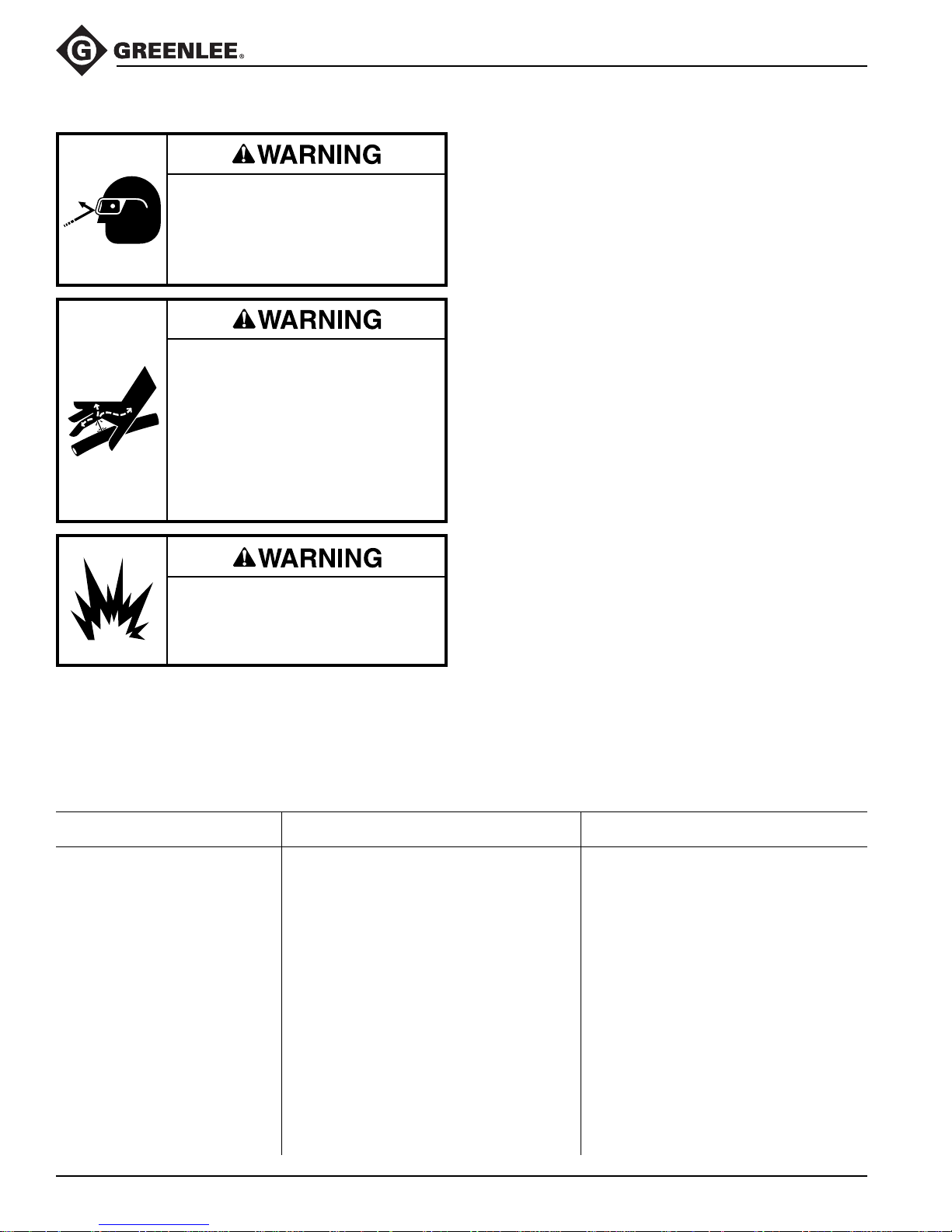
Wear eye protection when operating
or servicing this tool.
Failure to wear eye protection could
result in serious eye injury from
flying debris or hydraulic oil.
Skin injection hazard:
Do not use hands to check for oil
leaks. Oil under pressure easily
punctures skin. If injured, seek
medical attention immediately to
remove oil.
Failure to observe this warning could
result in serious injury, gangrene, or
death.
Do not use solvents or flammable
cleaners to clean the tool body.
Solvents could ignite, causing
serious injury or property damage.
Troubleshooting
CCCX and CCCXC Tools
Each Operating Day
Before use:
1. Inspect dies and adapters for wear or damage such
as cracks, gouges, or chips.
2. Inspect the tool for damage or leaks. If damage is
detected, return the tool to an authorized Greenlee
service center for inspection.
After use:
1. Wipe all tool surfaces clean with a damp cloth and
mild detergent.
2. Fully retract the ram. Place tool in the carrying case.
Store in a cool, dry place.
Monthly
1. Thoroughly clean all surfaces.
2. Check the oil level.
3. Oil the bolt joints.
Annually or After 10,000 Cycles
1. Change the hydraulic oil.
2. Return the tool to an authorized Greenlee service
center for inspection.
Checking the Oil Level
1. Remove the two screws holding the tank housing
cover.
2. Remove the tank housing cover.
3. Point the tool head towards the ground and remove
the oil plug. Add oil if necessary.
4. Replace the oil plug and the tank housing cover.
Secure with screws.
Recommended Hydraulic Oils
AVIA® HVI 15 Mobil® DTE 11M
Shell Tellus T 15 NUTO® H 15
Problem Probable Cause Probable Remedy
Tool is inoperative. Dirt, contaminants, etc., in ram area Clean tool.
of tool.
Tool components worn or damaged. Return tool to an authorized
Dies and adapters stop during Oil level is low. Check oil level. Refill reservoir.
operation.
Air in hydraulic system. Pull trigger and hold retract button
Tool loses oil. Damaged internal seal. Return tool to an authorized
Oil plug not installed properly. Refill reservoir and replace plug.
Greenlee / A Textron Company 18 4455 Boeing Dr. • Rockford, IL 61109-2988 USA • 815-397-7070
Greenlee service center.
simultaneously. Hold for approximately
10 seconds.
Greenlee service center.
Page 19

Disassembly
CCCX and CCCXC Tools
Main Components
1. Remove the pin (30). Remove the adapter ram (35).
2. Loosen two screws (24).
3. Unscrew and remove the universal head assembly.
4. Remove the sleeve (26), spring (25), and piston
(37). Replace the piston O-ring (21) and piston
backup ring (22).
5. Unscrew two tank cover screws (52) and remove the
tank cover.
6. Remove the hydraulic reservoir plug (76) and drain
the hydraulic fluid.
7. Reinstall the plug.
8. Remove the remaining housing screws (52).
9. Remove the housing half.
10. Remove the trigger cover and spring (56).
11. Lift the pump/motor assembly and circuit card from
the housing half.
12. Slide a plastic bag over the circuit card and electronic subassemblies. Tape the bag shut to protect
the subassemblies from hydraulic oil and other
contamination.
13. Unscrew the shoulder bolt (99) and remove the
release lever (107).
14. Remove screws (108) and separate the gear
housing/motor subassembly from the pump housing.
Pump
1. Use a hooked tool to remove the reservoir O-ring
(80). Gently tug it over the reservoir.
2. Remove the reservoir (74).
3. Remove the pump piston (152).
4. Remove the screw plug (151), washer (153), pump
piston (150), valve stem (156), and spring (155).
Replace the sealing washer (154).
5. Use a piece of tape to mark the side of the relief
that is facing up. (This is a reference point for
reassembly.) Remove the unloading valve by
unscrewing the plug (126).
6. Remove the feeder tube subassembly by unscrewing the feeder tube (78). Replace the oil filter (77).
Remove metal chips from the magnet (82).
7. Remove the threaded bushing (72) and replace the
O-ring (73).
Motor, Gearbox, and Bearing
1. Remove the tamper-proof paper seal (96).
2. Remove two screws (92). Remove the end cap
(102).
3. Apply pressure evenly at three points around the
ball bearing (91) and gently pry the bearing up to
remove it.
4. Remove the eccentric (103), grooved ball bearing
(101), and snap ring (100) subassembly from the
shaft.
5. Remove four screws (93). Remove the mounting
block (109) from the gear housing (94).
6. Use a snap-ring removal tool to remove the snap
ring (100).
7. Unscrew four bolts (not numbered) and hex nuts
(97) from the gear housing (94). Separate the gear
housing from the motor flange (110). Unscrew two
flat head screws (112) to separate the flange from
the motor (90).
Greenlee / A Textron Company 19 4455 Boeing Dr. • Rockford, IL 61109-2988 USA • 815-397-7070
Page 20

Assembly
CCCX and CCCXC Tools
Motor, Gearbox, and Bearing
1. Install four hex nuts (97) into the motor flange (110).
2. Install two flat head screws (112) into the motor
flange (110) and motor (90). Tighten the screws.
3. Install four screws (not numbered) and hex nuts (97)
into the gear housing (94). Tighten the screws.
4. Install four screws (93) into the mounting block (109)
and gear housing (94). Tighten the screws.
5. Replace the grooved ball bearing (101) and snap
ring (100).
6. Replace the eccentric (103). Use a fiber mallet to tap
the eccentric onto the shaft. Replace the ball bearing
(91).
7. Align the end cap (102). Use a fiber mallet to tap the
cover until it is flush on the mounting block (109).
Install two screws (92).
8. Align the gear housing/motor subassembly so that
the pump piston (152) extends through the mounting
block (109) and makes contact with the grooved
bearing (101). Locate and start the screws (108)
through the mounting block and into the pump
housing. Tighten the screws.
Pump
1. Insert the pump piston (152) into the pump housing.
2. Insert the seal (122) and unloading valve subassembly into the pump housing. Grasp the needle valve
subassembly by the plug (126) and twist it several
turns clockwise. Stop when the piece of tape is
facing up.
3. Assemble the pump piston (150), valve stem (156),
washer (153), spring (155), and screw plug (151).
Be sure to replace the sealing washer (154). Torque
the screw plug (151) to 102 Nm (75 ft-lb).
4. Install the release lever (107) so that the forked end
engages the unloading valve subassembly between
the pressure relief (126) and the support ring (127).
Install the screw (99) and washer (104).
5. Insert the threaded bushing (79) and feed tube
subassembly (77, 78, 82). Screw in until snug.
6. Install the reservoir (74). Slip the O-ring (80) over
the reservoir. Using a hooked tool, carefully slip the
O-ring over the lip of the pump housing.
7. Insert the plug (76) into the reservoir.
Main Components
1. Remove the protective plastic bag from the
electronics subassembly.
2. Lay the gear housing/motor subassembly into the
right half of the housing. Insert the circuit board into
the circuit board recess.
3. Lay the wires into the case. Be sure that the wires
will not be pinched.
4. Guide the wires for the power cord so that the cord
lays on top of the electronics box.
5. Install the switch cover and spring (56). Press and
release the trigger to be sure that it operates freely.
6. Locate the right housing half on the top of the left
housing half. Check for pinched wires.
7. Install the housing screws (52).
8. Install the piston (37).
9. Install the spring (25).
10. Replace the front head assembly. Twist the cutting
head base (31) until it stops; back off 3/4 of a turn
and tighten the screws (24). Be sure that the crimping head assembly rotates freely approximately
350°.
11. Install the adapter ram (35). Insert the pin (30)
through the ram.
12. Clamp the head assembly into a vise with the
reservoir plug facing upward. Remove the fill plug
(76) and fill the reservoir with hydraulic oil.
13. Plug the power cord into a live receptacle.
14. Squeeze the trigger while pressing the release lever
for 45 to 60 seconds. Fill the reservoir with hydraulic
oil. Replace the fill plug (76).
15.
Replace the tank cover and tank cover screws (52).
Greenlee / A Textron Company 20 4455 Boeing Dr. • Rockford, IL 61109-2988 USA • 815-397-7070
Page 21
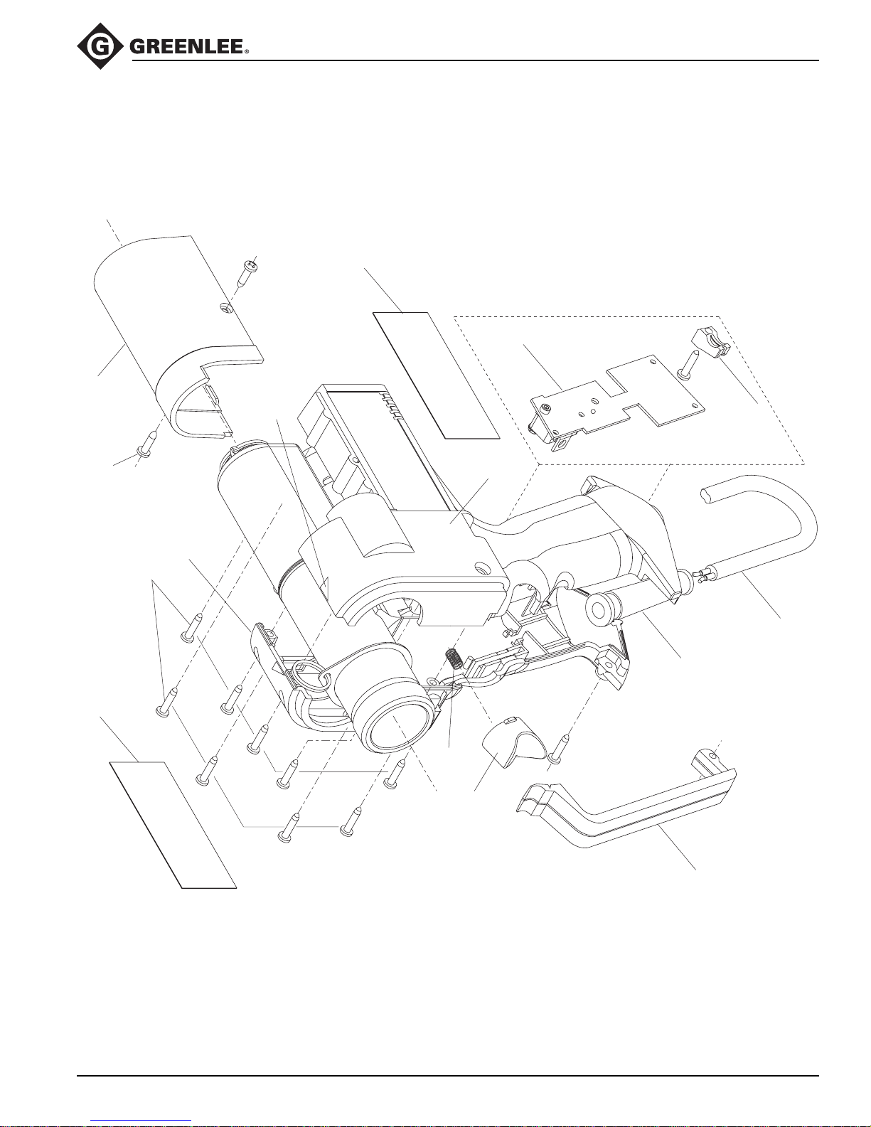
Illustration
50C
CCCX and CCCXC Tools
1
9
3
52
50B
52
2
56
50A
55
51
54
10
Greenlee / A Textron Company 21 4455 Boeing Dr. • Rockford, IL 61109-2988 USA • 815-397-7070
50D
Page 22
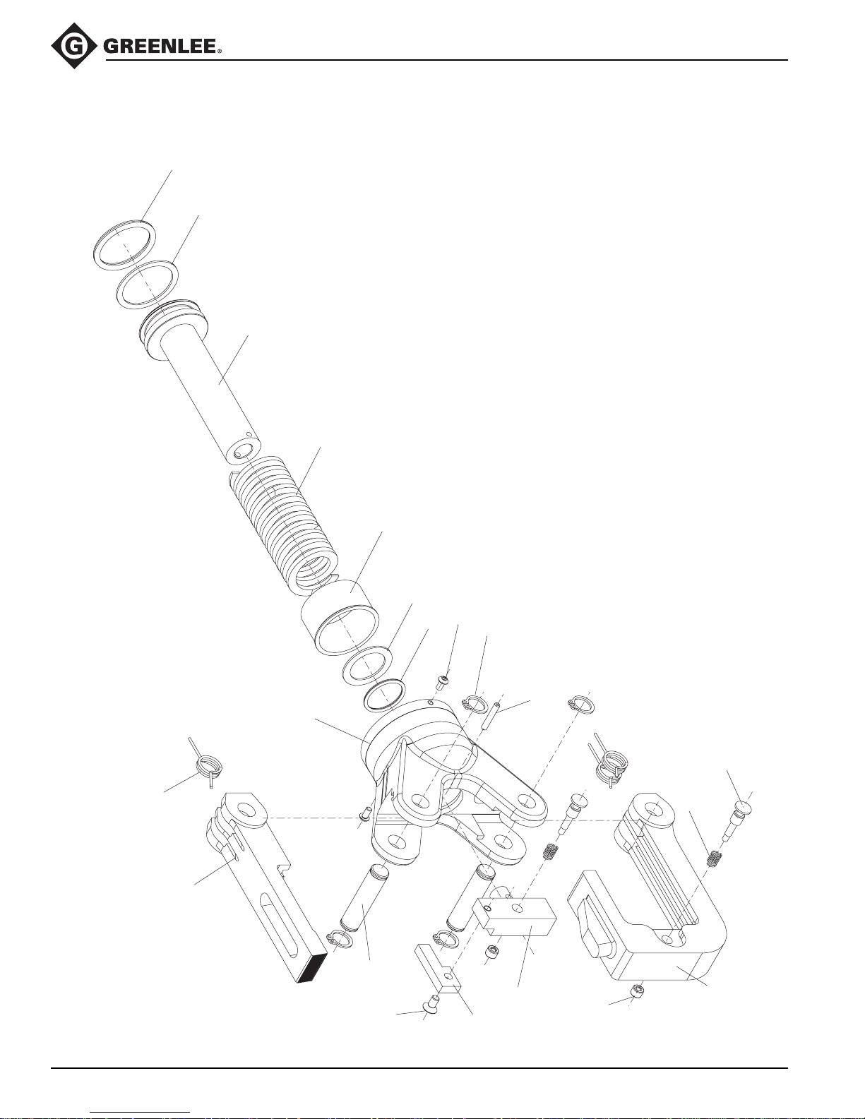
Illustration
CCCX and CCCXC Tools
21
22
37
25
20
33
31
26
27
28
24
40
30
38
23
Greenlee / A Textron Company 22 4455 Boeing Dr. • Rockford, IL 61109-2988 USA • 815-397-7070
36
29
34
35
32
39
Page 23
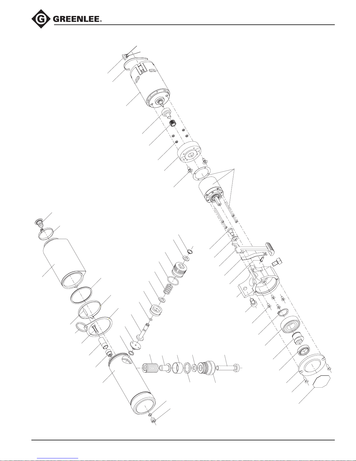
Illustration
CCCX and CCCXC Tools
11
12
90
95
111
74
76
71
82
75
77
78
79
80
70
122
81
123
129
121
124
120
155
97
130
125
110
126
156
112
127
128
150
153
99
104
107
105
152
94
106
109
108
93
100
101
103
91
83
Greenlee / A Textron Company 23 4455 Boeing Dr. • Rockford, IL 61109-2988 USA • 815-397-7070
73
72
154
151
102
92
96
Page 24

Parts List
CCCX and CCCXC Tools
Key Part No. Description Qty
1 500 1424.2 Decal, identification ........................................................................... 1
2 500 1425.0 Decal, safety, 120 volt ....................................................................... 1
500 1527.3 Decal, safety, 230 volt ....................................................................... 1
3 500 6214.0 Decal, pinch hazard........................................................................... 2
9 500 1560.5 Plate with microswitch, 120 volt ........................................................ 1
500 1689.0 Plate with microswitch, 230 volt ........................................................ 1
10 500 1561.3 Power cord, 120 volt.......................................................................... 1
500 1627.0 Power cord, 230 volt.......................................................................... 1
500 1559.1 Engine accessories kit (includes 11–13)
11 500 1582.6 Capacitor ........................................................................................... 3
12 500 1581.8 Cable tie ............................................................................................ 1
13 500 1583.4 Tap, 4.8 x 0.5 (not shown)................................................................. 1
500 1344.0 Head and ram unit (includes 20–40)
500 3223.2 Head and ram unit, PVC-covered (includes 20–40)
20 500 4383.8 Spring ................................................................................................ 3
21* O-ring ................................................................................................ 1
22* Backup ring, piston............................................................................ 1
23 Compression spring .......................................................................... 2
24 500 4168.1 Screw ................................................................................................ 2
25 500 5825.8 Compression spring .......................................................................... 1
26 500 5844.4 Bushing ............................................................................................. 1
27 500 5837.1 Adapter disk ...................................................................................... 1
28* O-ring ................................................................................................ 1
29 500 6725.7 Screw, M4 x 8.................................................................................... 1
30 500 7122.0 Pin, 3 x 18 ......................................................................................... 1
31 500 6715.0 Fixed head......................................................................................... 1
31A 500 3229.1 Fixed head, PVC-covered ................................................................. 1
32 Movable head.................................................................................... 1
32A Movable head, PVC-covered ............................................................ 1
33 Latch.................................................................................................. 1
33A Latch, PVC-covered .......................................................................... 1
34 500 6721.4 Guide plate ........................................................................................ 1
35 500 6719.2 Adapter ram....................................................................................... 1
36 500 6718.4 Pin, 10 x 40.5 mm ............................................................................. 2
37 500 6722.2 Piston ................................................................................................ 1
38 Adapter lock ...................................................................................... 2
39 Bushing ............................................................................................. 2
40 500 3430.8 Retaining ring .................................................................................... 4
Greenlee / A Textron Company 24 4455 Boeing Dr. • Rockford, IL 61109-2988 USA • 815-397-7070
Page 25

Parts List (cont’d)
Key Part No. Description Qty
50A Housing, left side............................................................................... 1
50B Housing, right side............................................................................. 1
50C Reservoir cover ................................................................................. 1
50D Trigger guard..................................................................................... 1
51 500 1564.8 Switch cover ...................................................................................... 1
52 500 4207.6 Screw .............................................................................................. 14
54 500 1565.6 Cable clip........................................................................................... 1
55 500 1567.2 Protective cable cover ....................................................................... 1
56 500 1569.9 Compression spring .......................................................................... 1
57 500 1571.0 Film insulation (not shown)................................................................ 1
58 500 1566.4 Plug (not shown) ............................................................................... 1
70 501 0340.7 Ring tie .............................................................................................. 1
71 500 7177.7 Cable tie ............................................................................................ 1
72 500 4144.4 Threaded bushing ............................................................................. 1
73* 500 4143.6 O-ring ................................................................................................ 1
74 500 5873.8 Hydraulic reservoir ............................................................................ 1
75 500 4198.3 Ring ................................................................................................... 1
76 500 5878.9 Reservoir plug ................................................................................... 1
77 500 5880.0 Filter .................................................................................................. 1
78 500 5882.7 Filter adapter ..................................................................................... 1
79 500 5885.1 Threaded bushing ............................................................................. 1
80* 500 5886.0 O-ring ................................................................................................ 1
81 500 5829.0 Attachment ring ................................................................................. 1
82 500 5898.3 Magnet .............................................................................................. 1
83 501 0364.4 Pump housing ................................................................................... 1
CCCX and CCCXC Tools
500 1563.0 Housing assembly, green (includes 50-58)
500 1346.7 Pump housing, reservoir assembly (includes 70–83)
500 1558.3 Motor assembly, 120 volt (includes 90A and 91–112)
500 1605.9 Motor assembly, 230 volt (includes 90B and 91–112)
90A 500 1577.0 Motor, 120 volt................................................................................... 1
90B 500 1606.7 Motor, 230 volt................................................................................... 1
91 500 4138.0 Ball bearing ....................................................................................... 1
92 500 4155.0 Screw ................................................................................................ 2
93 500 4157.6 Screw ................................................................................................ 4
94 500 1572.9 Gearbox............................................................................................. 1
95 500 1575.3 Insulating sleeve................................................................................ 1
96* 500 4153.3 Seal ................................................................................................... 1
97 500 1579.6 Hex nut .............................................................................................. 4
99 500 4163.0 Screw, socket head ........................................................................... 1
100 500 4151.7 Retaining ring .................................................................................... 1
101 500 4139.8 Grooved ball bearing ......................................................................... 1
102 500 4108.8 End cap ............................................................................................. 1
103 500 4123.1 Eccentric............................................................................................ 1
104 500 4922.4 Lock washer ...................................................................................... 1
105 500 4125.8 Spring ................................................................................................ 1
106 500 5872.0 Screw ................................................................................................ 1
Greenlee / A Textron Company 25 4455 Boeing Dr. • Rockford, IL 61109-2988 USA • 815-397-7070
Page 26

Parts List (cont’d)
Key Part No. Description Qty
107 500 5879.7 Release lever .................................................................................... 1
108 500 8403.8 Screw ................................................................................................ 2
109 500 8402.2 Eccentric case ................................................................................... 1
110 500 1573.7 Motor flange ...................................................................................... 1
111 500 1574.5 Gear .................................................................................................. 1
112 500 1580.0 Screw ................................................................................................ 2
120 500 5860.6 Washer .............................................................................................. 1
121* O-ring ................................................................................................ 1
122* Seal ................................................................................................... 1
123 500 5363.0 Valve seat.......................................................................................... 1
124 500 5864.9 Plunger .............................................................................................. 1
125* O-ring ................................................................................................ 1
126 500 5871.1 Adjusting nut...................................................................................... 1
127 500 5875.4 Support ring....................................................................................... 1
128* Retaining ring .................................................................................... 1
129 500 5877.0 Needle valve...................................................................................... 1
130 500 5894.0 Spring ................................................................................................ 1
CCCX and CCCXC Tools
500 1593.1 Relief valve assembly (includes 120–130)
500 1348.3 Piston pump assembly (includes 150–156)
150 500 5891.6 Pump piston ...................................................................................... 1
151 501 0365.2 Screw plug......................................................................................... 1
152 501 0370.9 Pump piston ...................................................................................... 1
153* Washer .............................................................................................. 1
154* Sealing washer.................................................................................. 1
155 501 0367.9 Spring ................................................................................................ 1
156 501 0368.7 Valve stem......................................................................................... 1
500 1426.9 Decal, connector compatibility
500 2183.4 Decal, tool accessories
500 1750.0 Head set (includes 32, 33)
500 3225.9 Head set, PVC-covered (includes 32A, 33A)
501 0375.0 Adapter lock kit (includes 23, 38, and 39)
* 500 1407.2 Seal kit (includes items marked with an asterisk)
500 1562.1 Case with inserts
Greenlee / A Textron Company 26 4455 Boeing Dr. • Rockford, IL 61109-2988 USA • 815-397-7070
USA 800-435-0786 Fax: 800-451-2632
815-397-7070 Fax: 815-397-1865
Canada 800-435-0786 Fax: 800-524-2853
International +1-815-397-7070 Fax: +1-815-397-9247
4455 Boeing Drive • Rockford, IL 61109-2988 • USA • 815-397-7070
An ISO 9001 Company
www.greenlee.com
•
Greenlee Textron Inc. is a subsidiary of Textron Inc.
 Loading...